Installation, Operation and Maintenance Bulletin OM49
Type ES49( )
4.9-Meter ESA
4.9-Meter Earth Station Antenna
Revision L
NoticeThe installation, maintenance, or removal of antenna systems requires qualified, experienced personnel. Andrew installa-tion instructions have been written for such personnel. Antenna systems should be inspected by qualified personnel toverify proper installation, maintenance and condition of equipment.Andrew Corporation disclaims any liability or responsibility for the results of improper or unsafe installation and mainte-nance practices.All designs, specifications, and availabilities of products and services presented in this manual are subject to changewithout notice.
Introduction Like all Andrew earth station antennas, the 4.9-Meter Earth Station Antenna provideshigh gain and exceptional pattern characteristics. The electrical performance and excep-tional versatility provides the ability to configure the antenna with your choice of linearly-or circularly-polarized 2-port or 4-port combining network. That versatility is provided atthe time of initial purchase, as well as in the future, as your satellite communicationrequirements evolve.
The aluminum reflector is precision formed for accuracy and strength requiring minimalassembly. The reflector assembly is 16-feet (4.9-meters) in diameter and segmented ina twelve piece configuration to reduce shipping volume and facilitate transport to remotesites. Reflector panels are conversion coated and painted with a flat white paint.
The manual pedestal tube mount features 360 degree azimuth coverage in continuous40 degree ranges and executes 90 degree (0 - 90 degree) continuous elevation adjust-ment. The manual mount also features ±20° of continuous fine azimuth adjustment. Thislarge adjustment range provides the ability to view geostationary satellites from horizon-to-horizon, from any location worldwide.
The motorizable pedestal tube mount may be purchased which features self-aligningbearings for the elevation pivots, resulting in "zero" backlash. This mount can be operat-ed manually, but has the ability to be upgraded for motorized operation, including step-tracking/Smartrack™ applications. The motorizable mount type is indicated by theES49MPJ letters within the antenna type number. The azimuth/elevation jackscrews areequipped for integration with the optional motor drive systems.
The aluminum enclosure and hot-dipped galvanized steel mount maintain pointing accu-racy and ensures durability and reliability. The antenna and standard manual mount withenclosure will survive 125 mph (200 km/h) wind, in any position of operation, withoutdamage or permanent deformation in moderate coastal/industrial areas. Severe condi-tions require additional protection.
Andrew provides a complete line of available options, including motor drive systems(with power interfaces addressing domestic and international standards), remote micro-processor antenna control for motor drive systems, pressurization equipment, and inter-connecting HELIAX® cables and waveguide.
3 Introduction
4.9-Meter Earth Station Antenna
Proprietary Data
Information andAssistance
Notice
TechnicalAssistance
The technical data contained herein is proprietary to Andrew Corporation. It is intendedfor use in operation and maintenance of Andrew supplied equipment. This data shall notbe disclosed or duplicated in whole or in part without express written consent of AndrewCorporation.
Andrew Corporation provides a world-wide technical support network. Refer to the tech-nical assistance portion of this this manual for the contact numbers appropriate to yourlocation.
The installation, maintenance, or removal of antenna systems requires qualified, experi-enced personnel. Andrew installation instructions have been written for such personnel.Antenna systems should be inspected by qualified personnel to verify proper installation,maintenance and condition of equipment.
Andrew Corporation disclaims any liability or responsibility for the results of improper orunsafe installation and maintenance practices.
All designs, specifications, and availabilities of products and services presented in thismanual are subject to change without notice.
For technical assistance, call the following numbers at anytime.
Call From Call To Telephone Fax
North America (toll free) U. S. A. +(1) 800-255-1479 +(1) 800-349-5444
Any Location U. S. A. +(1) 708-349-3300 +(1) 708-349-5410(International)
Customer Service Center
The Andrew Customer Service Center gives you direct access to the information andpersonnel service you need, such as the following:
• Place or change orders
• Check price and delivery information
• Request technical literature
You can call from any of the following:
Call From Telephone Fax
North America +(1) 800-255-1479 (toll free) +(1) 800-349-5444 (toll free)
United Kingdom 0800-250055 (toll free) 44-118-9366-777
Australia 1-800-803-219 (toll free) 61-3-93579110
China 00-800-0-255-1479 00-800-0-349-5444
New Zealand 0800-441-747 (toll free) 61-3-3579110
Hong Kong 001-800-0-255-1479 002-800-0-349-5444
Overview
Content
The scope of this manual is intended to provide station personnel with the base installa-tion, operation, and maintenance requirements necessary for a 4.9-Meter C-, X-, Ku- orK-band Earth Station Antenna. This manual provides a convenient reference for autho-rized operator/service personnel requiring technical information on general system orspecific subsystem equipment.
The tables and figures presented in this manual are used as communication aids for theinstallation, operation, and maintenance of the 4.9-Meter Earth Station Antenna. Thesetables and figures instantly convey messages, as well as make the procedures easier tounderstand. This manual uses tables and figures for the following references:
• Tables The tables allow you to locate information quickly and easily.
• Drawings The drawings supplement the installation instructions by using a combi-nation of graphics and verbiage to assist you in simplifying complex pro-cedures and clarifying components.
• Photographs The photographs compliment the installation instructions by providing actual examples of the steps being performed, which allow you to view the installation progress in the proper sequence.
The manual is divided into five distinct sections, each dealing with a specific technicaltopic relating to either system or component subsystem information. The sections con-tained in this manual are described and listed under the following technical headings:
• How to Use Describes the manual's purpose, content, and communication aids. This Manual Additionally, this section lists the related documentation for the 4.9-
Meter Earth Station Antenna.
• Getting Provides the preliminary information needed to perform a successful Started installation. This section should be reviewed prior to the installation. The
warnings, recommended tools, parts verification, instructions on report-ing lost or damaged equipment, and installation checklist are located in this section.
• Installation Provides the procedures for the different phases of a 4.9-Meter Earth Procedures Station Antenna base installation. This section will help you easily find
requirements for an individual task, as well as displays the sequence foreach task execution.
• Operation Describes the controls, functions, and general operating procedures required for proper operation of the 4.9-Meter Andrew Earth Station Antenna.
• Preventive Describes preventive maintenance procedures that are required toMaintenance maintain proper functional operation of your new Andrew Earth Station
Antenna.
5 How to Use This Manual
How to Use This Manual
Overview
Warnings
The installation, operation, and maintenance of the 4.9-Meter Earth Station Antennarequires qualified and experienced personnel. Andrew installation, operation, and main-tenance instructions are illustrated for such personnel. Additionally, the antenna shouldbe inspected by qualified personnel to verify proper installation, maintenance, and con-dition of equipment as described in Preventive Maintenance. The basic equipment andaccessories are either manufactured or design controlled by Andrew Corporation.
The prerequisite information necessary for the 4.9-Meter Earth Station Antenna can befound in this section. Furthermore, this section should be reviewed BEFORE performingthe installation, operation, or maintenance. Recommended warnings, recommendedtools, and the antenna parts can be verified and/or determined with such a review.
When installing the 4.9-Meter Earth Station Antenna, be conscious of the recommendedwarnings presented below. For further information or clarification of this information,contact the Customer Service Center. The recommended warnings are as follows:
1. Electrical shock from voltages used in this antenna system may cause personal injuryor death. Prior to making any electrical connections or performing maintenance orrepair, ensure that the power is removed. Electrical connections should be made only byqualified personnel in accordance with local regulations.
2. Installation of antennas may require persons to work at elevated work stations.Whenever persons are working at eight or more feet above the ground and not on aguarded platform, they should wear safety belts with at least one (preferably two) lan-yards.
3. Never stand underneath any object while it is being lifted.
4. Always wear a hard hat, especially if someone is above you.
5. Make sure no person is in or under the reflector while it is being lifted or positioned;personal injury can result if the reflector assembly falls.
6. Personnel should never be hoisted in or out of the reflector by the crane; personalinjury may result.
7. Andrew earth station antennas supplied to standard product specifications will survive125 mph winds in any operational position in moderate coastal/industrial areas. Severeconditions require additional protection. Should it be expected that winds will exceed125 mph, it is recommended that Andrew antennas be steered to specific azimuth andelevation orientations (refer to #8) to minimize wind forces upon the structure and there-by increase the probability of survival.
8. It is recommended that all cross-axis waveguide and coaxial cables are secure suchthat high winds will not cause excessive flexing. Position the antenna to an elevation of90 degrees. The azimuth jackscrew should be placed in the center of its travel.
9. When the antenna is transmitting, severe eye injury or injury to other parts of thebody can result from exposure to radio frequency (RF) energy. The antenna must beturned off before entering the area in front of the reflector and near the feed.
6 Getting Started
Getting Started
RecommendedTools
NOTE: Failure to follow an installation procedure could result in damage to equipmentor personal injury.
Additional warnings will be displayed throughout this manual for your awareness. Thesewarnings can be identified in warning boxes as shown in the following sample.
Andrew disclaims any liability or responsibility for the results of improper or unsafeinstallation, operation, or maintenance practices.
Andrew supplies all appropriate hardware/parts required for the installation of your 4.9-Meter Earth Station Antenna. All tools necessary for the installation process should beprovided by the installation crew. Andrew recommends the following tools to be used fora proper installation of the 4.9-Meter Earth Station Antenna.
Tool Size QuantityOpen End or Combination Wrenches 7/16 Inch 2
1/2 Inch 29/16 Inch 23/4 Inch 27/8 Inch 21-1/16 Inch 21-1/8 Inch 21-3/16 Inch 21-1/4 Inch 21-5/16 Inch 21-3/8 Inch 21-7/16 Inch 21-1/2 Inch 21-5/8 Inch 21-9/16 Inch 13-1/16 Inch 1
Pipe Wrench 3 Inch Opening 1Spud Wrench 1-1/4 Inch 1Crane 15 Ton 1Nylon Choker (3/8” dia) 6 Foot 2Nylon Choker (3/8” dia) 3 Foot 2Choker (1/2” dia) 16 Foot 4Shackles 5/8 Inch 4Puller Hoist 1 Ton 1Drive Sockets (1/2”) 7/16 Inch 2
1/2 Inch 29/16 Inch 23/4 Inch 27/8 Inch 21-1/16 Inch 21-1/4 Inch 21-1/2 Inch 2
Drive Ratchet 1/2 Inch 2Drive Extension 1/2 Inch 2Screw Driver Slotted and Phillips 2Portable Electric Drill 1Adjustable Wrench 8 Inch 1Allen Wrench 5/16 Inch 4
3/16 Inch 41/4 Inch 45/32 Inch 47/64 Inch 4
Tag Line 20 Foot 4Step Ladder 12 Foot 2Extension Ladder 25 Foot 2Felt-tip Marker (or other marking device) Standard 1Hammer Standard 1Tape Measure 25 Foot 1Rubber Mallet Standard 1Pry Bar Standard 1Tin Snips Standard 1Temporary Wood Support Lumber 2 x 4 x 8 Foot 4Temporary Wood Support Blocks 4Safety Gloves (each installer) Standard 1Electronic Digital Level or Equivalent Standard 1Caulk Gun (Sealant Applicator) Standard 1
7 Getting Started
Parts Verification
ReportingEquipment Loss or
DamageReporting VisibleLoss or Damage
ReportingConcealed
Damage
InventoryEquipment
Received
Andrew Corporation thoroughly inspects and carefully packs all equipment before ship-ment. If you find that there are missing components, please notify Andrew Corporationimmediately by contacting the Customer Service Center (refer to page 4).
If you find that there was damage caused to the equipment during the shipping process,a claim should be filed with the carrier. Follow the "Reporting Visible Loss or Damage"or "Reporting Concealed Damage" procedures when filing a claim with the carrier.
Make a note of any loss or evidence of external damage on the freight bill or receipt,and have it signed by the carrier's agent. Failure to adequately describe such externalevidence of loss or damage may result in the carrier refusing to honor a damage claim.The form required to file such a claim will be supplied by the carrier.
Concealed damage means damage which does not become apparent until the unit hasbeen unpacked. The contents may be damaged in transit due to rough handling, eventhough the carton may not show external damage. If you discover damage after unpack-ing the unit, make a written request for an inspection by the carrier's agent, then file aclaim with the carrier since such damage is most likely the carrier's responsibility.
After opening your shipment, an inventory of the parts should occur immediately. Checkeach item received in your shipment against the packing slip included with the shipment.If any items are missing, please refer to page 9 for step-by-step instructions on how toproperly report the equipment loss.
8 Getting Started
ReturningEquipment
Step 1
Step 2
Step 3
Step 4
Step 5
Andrew Corporation tries to ensure that all items arrive safe and in working order.Occasionally, despite these efforts, equipment is received which is not in working condi-tion. When this occurs, and it is necessary to return the equipment to AndrewCorporation for either repair or replacement, return can be expedited by following theprocedure listed below:
Call the Andrew Customer Service Center and request a Return Material Authorization(RMA) number, as well as an address to forward the material.
Tag or identify the defective equipment, noting the defect or circumstances. Also, besure to write the RMA number on the tag. It would be helpful to reference the salesorder and purchase order, as well as the date the equipment was received.
Pack the equipment in its original container with protective packing material. If the origi-nal container and packing material are no longer available; pack the equipment in asturdy corrugated box, and cushion it with appropriate packing material.
Be sure to include the following information when returning the equipment:
• Your Company Name
• Your Company Address
• City, State, and Zip Code
• Telephone Number
• RMA Number
• Problem Description
• Contact Name
NOTE: Absence of the RMA number will cause a delay in processing your equipmentfor repair. Be sure to include the RMA number on all correspondence.
Ship the equipment to Andrew Corporation using UPS, U.S. Postal Service, or otherappropriate carrier; freight prepaid and insured. The material should be forwarded to theaddress given by the Andrew contact in Step 1.
9 Getting Started
Overview
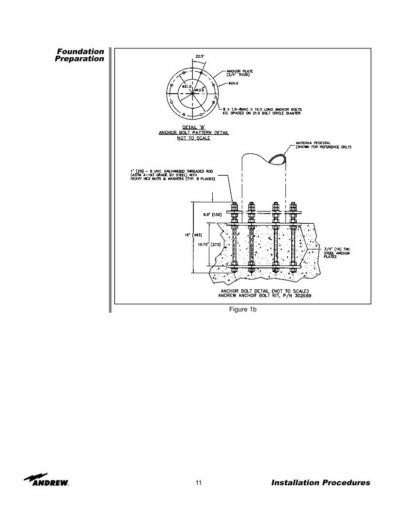
FoundationPreparation
10 Installation Procedures
This section provides installation procedures for the 4.9-Meter Andrew Earth StationAntenna. The installation procedures include instructions on the following antenna com-ponents:
• Reflector/Enclosure • Reflector-to-Mount Assembly• Mount • Subreflector
Before beginning the installation process on the ground mount assembly, ensure thatthe foundation has been prepared. Foundation specifications are provided by Andrewand may be used as a reference by civil engineering personnel when preparing thefoundation for local soil conditions. These specifications are available before the ship-ment arrives by contacting the Customer Service Center or your Account Manager.
• Foundation should be dimensioned as detailed in Figures 1a and 1b.• Sweep foundation clear of any dirt or debris.• To ensure smooth surface for mount, scrape foundation pad.• Studs should extend 6 in. above the surface and are 1.25 in. in diameter• Apply stick wax to stud threads to ease later connections.
Installation Procedures
Figure 1a
11 Installation Procedures
Figure 1b
FoundationPreparation
Foundation Notes
12 Installation Procedures
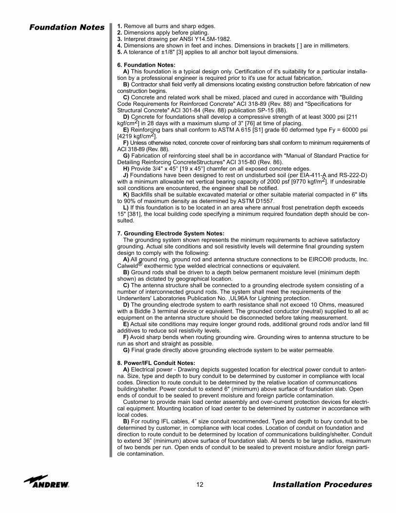
1. Remove all burrs and sharp edges.2. Dimensions apply before plating.3. Interpret drawing per ANSI Y14.5M-1982.4. Dimensions are shown in feet and inches. Dimensions in brackets [ ] are in millimeters.5. A tolerance of ±1/8" [3] applies to all anchor bolt layout dimensions.
6. Foundation Notes:A) This foundation is a typical design only. Certification of it's suitability for a particular installa-
tion by a professional engineer is required prior to it's use for actual fabrication.B) Contractor shall field verify all dimensions locating existing construction before fabrication of new
construction begins.C) Concrete and related work shall be mixed, placed and cured in accordance with "Building
Code Requirements for Reinforced Concrete" ACI 318-89 (Rev. 88) and "Specifications forStructural Concrete" ACI 301-84 (Rev. 88) publication SP-15 (88).
D) Concrete for foundations shall develop a compressive strength of at least 3000 psi [211kgf/cm2] in 28 days with a maximum slump of 3" [76] at time of placing.
E) Reinforcing bars shall conform to ASTM A 615 [S1] grade 60 deformed type Fy = 60000 psi[4219 kgf/cm2].
F) Unless otherwise noted, concrete cover of reinforcing bars shall conform to minimum requirements ofACI 318-89 (Rev. 88).
G) Fabrication of reinforcing steel shall be in accordance with "Manual of Standard Practice forDetailing Reinforcing ConcreteStructures" ACI 315-80 (Rev. 86).
H) Provide 3/4" x 45° [19 x 45°] chamfer on all exposed concrete edges.J) Foundations have been designed to rest on undisturbed soil (per EIA-411-A and RS-222-D)
with a minimum allowable net vertical bearing capacity of 2000 psf [9770 kgf/m2]. If undesirablesoil conditions are encountered, the engineer shall be notified.
K) Backfills shall be suitable excavated material or other suitable material compacted in 6" liftsto 90% of maximum density as determined by ASTM D1557.
L) If this foundation is to be located in an area where annual frost penetration depth exceeds15" [381], the local building code specifying a minimum required foundation depth should be con-sulted.
7. Grounding Electrode System Notes:The grounding system shown represents the minimum requirements to achieve satisfactory
grounding. Actual site conditions and soil resistivity levels will determine final grounding systemdesign to comply with the following:
A) All ground ring, ground rod and antenna structure connections to be EIRCO® products, Inc.Calweld® exothermic type welded electrical connections or equivalent.
B) Ground rods shall be driven to a depth below permanent moisture level (minimum depthshown) as dictated by geographical location.
C) The antenna structure shall be connected to a grounding electrode system consisting of anumber of interconnected ground rods. The system shall meet the requirements of theUnderwriters' Laboratories Publication No. ,UL96A for Lightning protection.
D) The grounding electrode system to earth resistance shall not exceed 10 Ohms, measuredwith a Biddle 3 terminal device or equivalent. The grounded conductor (neutral) supplied to all acequipment on the antenna structure should be disconnected before taking measurement.
E) Actual site conditions may require longer ground rods, additional ground rods and/or land filladditives to reduce soil resistivity levels.
F) Avoid sharp bends when routing grounding wire. Grounding wires to antenna structure to berun as short and straight as possible.
G) Final grade directly above grounding electrode system to be water permeable.
8. Power/IFL Conduit Notes:A) Electrical power - Drawing depicts suggested location for electrical power conduit to anten-
na. Size, type and depth to bury conduit to be determined by customer in compliance with localcodes. Direction to route conduit to be determined by the relative location of communcationsbuilding/shelter. Power conduit to extend 6" (minimum) above surface of foundation slab. Openends of conduit to be sealed to prevent moisture and foreign particle contamination.
Customer to provide main load center assembly and over-current protection devices for electri-cal equipment. Mounting location of load center to be determined by customer in accordance withlocal codes.
B) For routing IFL cables, 4” size conduit recommended. Type and depth to bury conduit to bedetermined by customer, in compliance with local codes. Location of conduit on foundation anddirection to route conduit to be determined by location of communications building/shelter. Conduitto extend 36” (minimum) above surface of foundation slab. All bends to be large radius, maximumof two bends per run. Open ends of conduit to be sealed to prevent moisture and/or foreign parti-cle contamination.
A325 Tensioning
Step 1
Step 2
Step 3
Step 4
Step 5
Step 6
13
During the installation process, there are several references to the A325 hardware ten-sioning procedure. The A325 hardware must be properly tensioned to avoid slippagebetween bolted surfaces under high loads. Slippage can cause the correspondingassembly to move, causing antenna misalignment. When designated, the A325 hard-ware should be tightened according to the following tensioning procedure.NOTE: Tensioned bolts are for final connections only and should not be loosened forreuse.
Lubricate the bolt threads with the provided stick wax to reduce friction.
Insert the bolt, and add a flat washer—if required. Do not allow wax under the flatwasher.
Add the nut, and finger tighten.
After the connections are complete, tighten the bolts until the surfaces are joined andthe nuts are snug (for example, full effort of a person using an ordinary spud wrench).Do not proceed with Steps 5 and 6, unless the connection is final and is not intended tobe loosened again.
Note: If the bolts are loosened after Steps 5 and 6, discard and replace with new hard-ware.
Using a felt-tip marker, mark the nuts and the ends of the bolts with a straight line asshown in Figure 2-1a and Figure 2-1b.
Tighten the nuts further with an extra long wrench until the nuts are moved 1/3 turn (120degrees) as shown in Figure 3-1a for bolt lengths less than four diameters and 1/2turn (180 degrees) as shown in Figure 3-1b for bolt lengths over four diameters.
Figure 2-1a: A325 Tensioning ProcedureFigure 2-1b: A325 TensioningFor bolts less than 4 diameters For bolts over four diameters
Installation Procedures
Use Felt Marker
BeforeTensioning
AfterTensioning
Use Felt Marker
BeforeTensioning
AfterTensioning
Reflector/BackStructureAssembly
Step 1
14 Installation Procedures
Use of A325 hardware eliminates slippage between mating surfaces under high loadingconditions as well as the need for future retightening. Refer to the A325 tensioning pro-cedure in preceding installation text. CAUTION: Adhere to any special instructions sten-ciled on crate relative to crate opening, contents removal and/or personnel safety.
Note: Install reflector/back structure assembly only when winds are less than 15 mph toprevent damage to reflector panels and ease overall assembly.
Position 302649 Hub Assembly on 4 temporary wood support blocks and attach 302648Short Struts to the Hub Assembly as shown in Figure 3.
Note: Securely tighten all stainless shoulder bolts followed by any A325 hardware fol-lowing the A325 Hardware tensioning procedure mentioned previously.
Figure 3
302649Hub Assembly
302648Short Strut
1/2”Hex Nut
(9999-61)
1/2”Lock
Washer(9974-64)
3/8”Hex Nut
(9999-60)
3/8”Lock
Washer(9974-63)
3/8” ID x7/8” OD
FlatWasher
(9997-145)
302649Hub Assembly
302648Short Strut
1/2” x 2-1/2”Hex HeadCapscrew(9963-137)
1/2” x 1-1/4”Shoulder
Bolt(9858-39)
1/2” ID x1” ODFlat
Washer(9997-65)
18” to 24”
1/2” ID x1” ODFlat
Washer(9997-65)
1/2”Hex Nut
(9999-61)
1/2”Lock
Washer(9974-64)
1/2” ID x1” ODFlat
Washer(9997-65)
1/2” ID x1” ODFlat
Washer(9997-65)
1/2” x 2-1/2”Hex HeadCapscrew(9963-137)
3/8”Hex Nut
(9999-60)
3/8”Lock
Washer(9974-63)
3/8” ID x 7/8” ODFlat Washer(9997-145)
1/2” ID x1” ODFlat
Washer(9997-65)
1/2” x 1-1/4”Shoulder
Bolt(9858-39)
Top of Hub Assembly
Rear View of Hub
Rib #1 Rib #12
Rib #2
Rib #3
Rib #4
Rib #5
Rib #6 Rib #7
Rib #8
Rib #9
Rib #11
Rib #10
1/2” ID x1” ODFlat
Washer(9997-65)
Top View
Short StrutExtends Above Top
of Antenna HubRound FeedHole Faces
Upward
Reference Drawing 240270
Step 2
Step 3
15 Installation Procedures
Loosely attach 302511 Ribs to 302648 Short Struts as shown in Figure 4. Note: Do notfully tighten hardware at this time. Support end of rib until 302509 Long Strut is installed.
Figure 4
Loosely attach 302509 Long Struts to 302648 Short Struts and 302511 Ribs as shown inFigures 5a and 5b. Do not fully tighten hardware at this time. Note: Observe placementof 209765-1 1/4” Spacer between the long and short struts.
Figure 5a
302511Rib 5/8” x 1/2”
ShoulderBolt
(9858-36)
302648Short Strut
302648Short Strut
302509Long Strut
5/8” x 3/4”Shoulder Bolt
(9858-31)
1/4”Spacer
(209765-1)
1/2”Hex Nut
(9999-61)
1/2”Hex Nut
(9999-61)
1/2”Lock
Washer(9974-64)
1/2” ID 1”ODFlat
Washer(9997-65)
Note: TemporarilySupport Rib Until
302509 LongStrut is Installed
1/2” ID 1”ODFlat
Washer(9997-65)
1/2”Lock
Washer(9974-64)
Reference Drawing 240272
Reference Drawing 240272
Step 4
Step 5
16 Installation Procedures
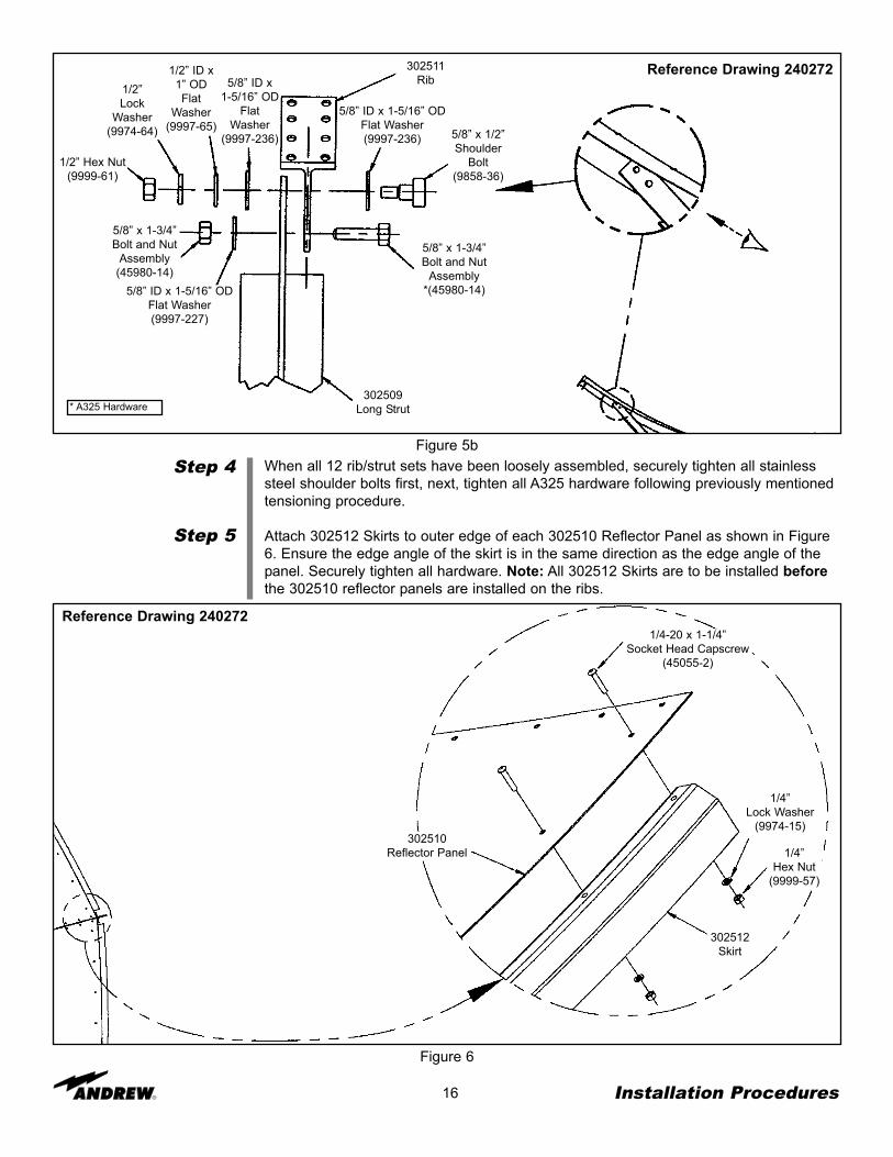
When all 12 rib/strut sets have been loosely assembled, securely tighten all stainlesssteel shoulder bolts first, next, tighten all A325 hardware following previously mentionedtensioning procedure.
Attach 302512 Skirts to outer edge of each 302510 Reflector Panel as shown in Figure6. Ensure the edge angle of the skirt is in the same direction as the edge angle of thepanel. Securely tighten all hardware. Note: All 302512 Skirts are to be installed beforethe 302510 reflector panels are installed on the ribs.
Figure 6
1/4-20 x 1-1/4”Socket Head Capscrew
(45055-2)
302510Reflector Panel
302512Skirt
1/4”Lock Washer
(9974-15)
1/4”Hex Nut
(9999-57)
Figure 5b
302509Long Strut
302511Rib
5/8” x 1/2”Shoulder
Bolt(9858-36)
5/8” x 1-3/4”Bolt and Nut
Assembly*(45980-14)5/8” ID x 1-5/16” OD
Flat Washer(9997-227)
5/8” x 1-3/4”Bolt and Nut
Assembly(45980-14)
1/2” Hex Nut(9999-61)
1/2”Lock
Washer(9974-64)
5/8” ID x1-5/16” OD
FlatWasher
(9997-236)
5/8” ID x 1-5/16” ODFlat Washer(9997-236)
1/2” ID x1” ODFlat
Washer(9997-65)
Reference Drawing 240272
Reference Drawing 240272
* A325 Hardware
17 Installation Procedures
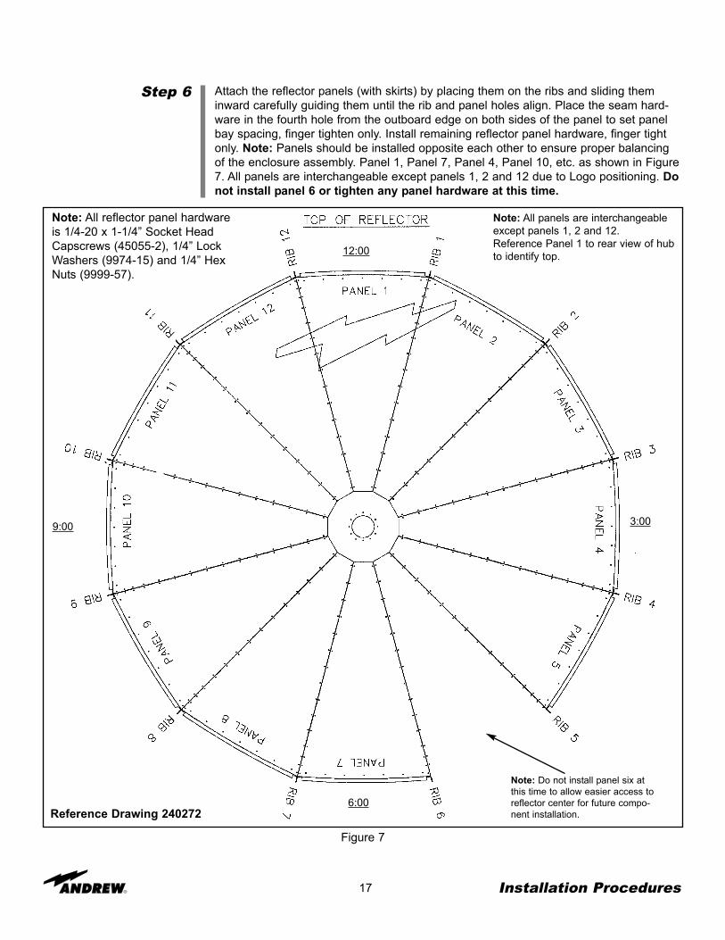
Step 6 Attach the reflector panels (with skirts) by placing them on the ribs and sliding theminward carefully guiding them until the rib and panel holes align. Place the seam hard-ware in the fourth hole from the outboard edge on both sides of the panel to set panelbay spacing, finger tighten only. Install remaining reflector panel hardware, finger tightonly. Note: Panels should be installed opposite each other to ensure proper balancingof the enclosure assembly. Panel 1, Panel 7, Panel 4, Panel 10, etc. as shown in Figure7. All panels are interchangeable except panels 1, 2 and 12 due to Logo positioning. Donot install panel 6 or tighten any panel hardware at this time.
Figure 7
Note: All panels are interchangeableexcept panels 1, 2 and 12.Reference Panel 1 to rear view of hubto identify top.
Note: All reflector panel hardwareis 1/4-20 x 1-1/4” Socket HeadCapscrews (45055-2), 1/4” LockWashers (9974-15) and 1/4” HexNuts (9999-57).
Reference Drawing 240272
Note: Do not install panel six atthis time to allow easier access toreflector center for future compo-nent installation.
12:00
6:00
3:009:00
SubreflectorSupport Brackets
Step 1
18 Installation Procedures
Attach four 206278 lifting tabs across the second and third pairs of reflector seam holesfrom reflector center on ribs 1, 4, 7 and 10, as shown in Figure 8. Note: Do not fullytighten lifting tab hardware at this time.
Figure 8
206278Lifting Tab
1/4 x 1-1/4”Socket Head
Capscrew(45055-2)
1/4”Lock
Washer(9974-15)
1/4”HexNut
(9999-57)
Note: To be removed after reflec-tor installation on ground mount.
Reference Drawing 240272
Step 2
Step 3
19 Installation Procedures
Attach the four 302518 Subreflector Support Brackets at the 15th (outer most) reflectorpanel hole position from reflector center on ribs 2, 5, 8, and 11 as shown in Figure 9.Note: Do not fully tighten subreflector support bracket hardware at this time.
Figure 9
Check reflector panels to ensure seam widths are even and panels are not overlappedor interfering with each other. If needed gently rock the reflector back and forth to helpeven the panel seam gaps.
1/4” Lock Washer(9974-15)
1/4 x 1-1/4” Socket HeadCapscrew (45055-2)
1/4” Hex Nut(9999-57)
302518Subreflector StrutSupport Bracket
Panel
Reference Drawing 240272
Rotating TubeAssembly
Step 1
Step 2
Step 3
20 Installation Procedures
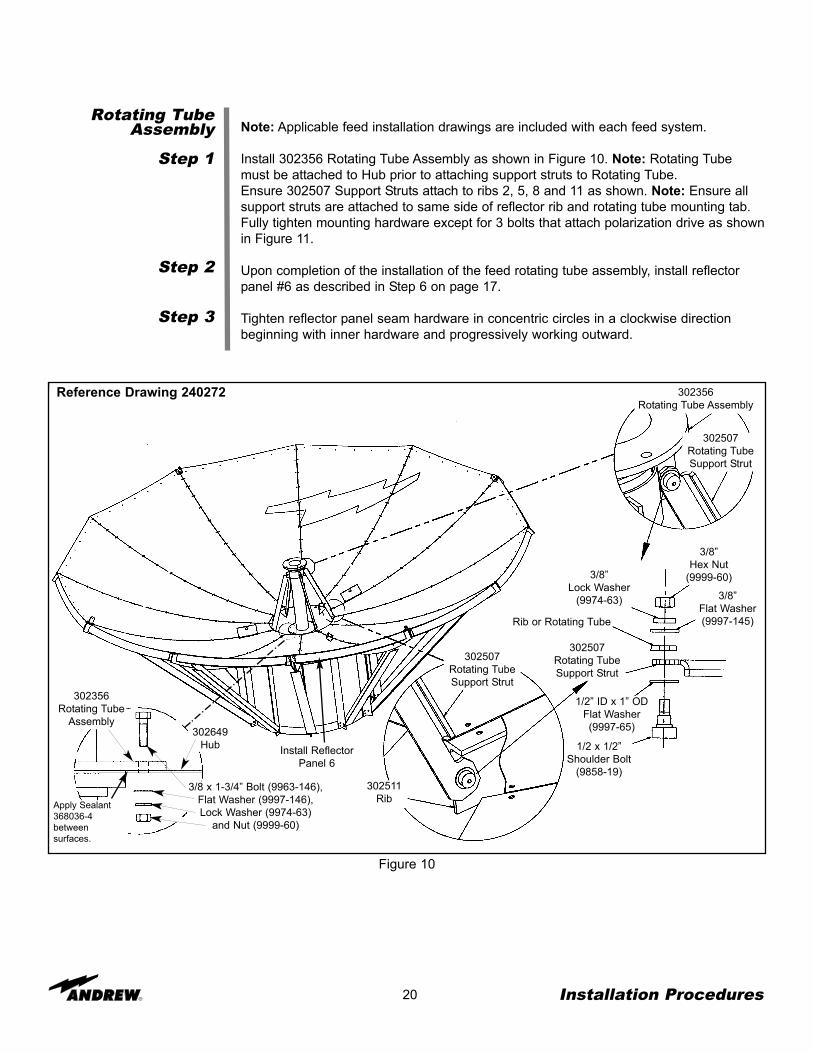
Note: Applicable feed installation drawings are included with each feed system.
Install 302356 Rotating Tube Assembly as shown in Figure 10. Note: Rotating Tubemust be attached to Hub prior to attaching support struts to Rotating Tube. Ensure 302507 Support Struts attach to ribs 2, 5, 8 and 11 as shown. Note: Ensure allsupport struts are attached to same side of reflector rib and rotating tube mounting tab.Fully tighten mounting hardware except for 3 bolts that attach polarization drive as shownin Figure 11.
Upon completion of the installation of the feed rotating tube assembly, install reflectorpanel #6 as described in Step 6 on page 17.
Tighten reflector panel seam hardware in concentric circles in a clockwise directionbeginning with inner hardware and progressively working outward.
Figure 10
302356Rotating Tube Assembly
302507Rotating TubeSupport Strut
302507Rotating TubeSupport Strut
3/8”Hex Nut
(9999-60)3/8”Lock Washer
(9974-63) 3/8”Flat Washer(9997-145)Rib or Rotating Tube
302507Rotating TubeSupport Strut
1/2” ID x 1” ODFlat Washer(9997-65)
1/2 x 1/2”Shoulder Bolt
(9858-19)302511
Rib
302649Hub
302356Rotating Tube
Assembly
3/8 x 1-3/4” Bolt (9963-146),Flat Washer (9997-146),Lock Washer (9974-63)
and Nut (9999-60)
Reference Drawing 240272
Install ReflectorPanel 6
Apply Sealant368036-4betweensurfaces.
21 Installation Procedures
Polarization DriveInstallation
Step 1
Step 2
Step 3
Attach the Polarization Drive Assembly as shown in Figure 11. Measure and cut chain toproper length.
Attach chain to coupling link on each end with supplied connecting link.
Pull pillow blocks and sprocket assembly back until chain is tight. Tighten bolts holdingpillow blocks in place.
Note: If a motorized polarization drive or LNA support kit is to be installed, ensure theseinstallations are complete before installing the combiner.
Note: When installing the feed combiner, rotate the feed tube all the way in either direc-tion. The polarization orientation can be better determined while in this position.
Rear View
302365Manual
PolarizationDrive Assembly
Chain
3/8 x 3/4”Socket Head Bolt
(9972-87)
1/4 x 3/4” Socket Head Screw (9972-6),.19 x 1.25” Socket Head Screw (9972-59)
and #10 Lock Washer (9974-68)
PillowBlocks
302374Chain Connecting
Link
#6-32 UNC x 1/2” (9972-46)and #6 Lock Washer (9974-67)
302342Coupling Link
302346Tube
RotationStop
Figure 11
22 Installation Procedures
SubreflectorAssembly
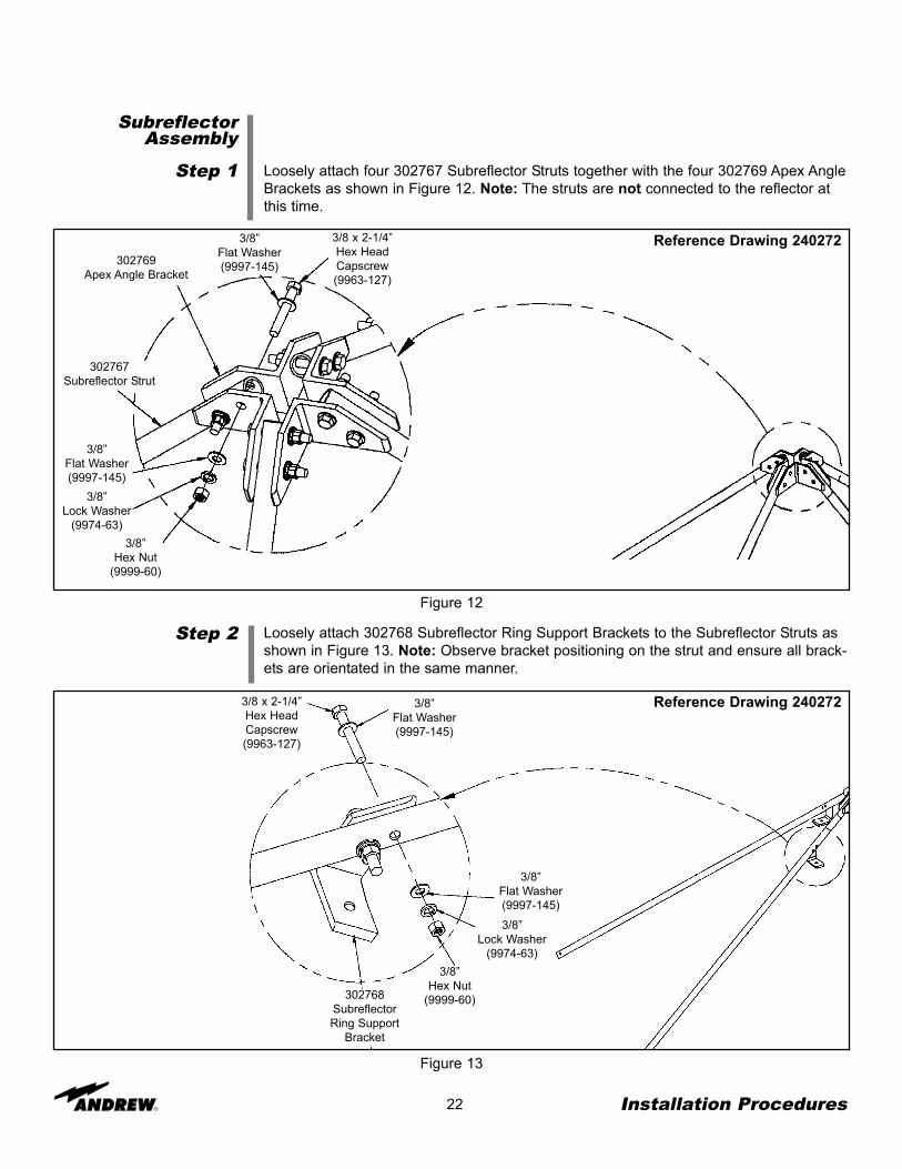
Step 1 Loosely attach four 302767 Subreflector Struts together with the four 302769 Apex AngleBrackets as shown in Figure 12. Note: The struts are not connected to the reflector atthis time.
Step 2 Loosely attach 302768 Subreflector Ring Support Brackets to the Subreflector Struts asshown in Figure 13. Note: Observe bracket positioning on the strut and ensure all brack-ets are orientated in the same manner.
Figure 12
Figure 13
3/8 x 2-1/4”Hex HeadCapscrew(9963-127)
3/8”Flat Washer(9997-145)302769
Apex Angle Bracket
302767Subreflector Strut
3/8”Flat Washer(9997-145)
3/8”Lock Washer
(9974-63)3/8”
Hex Nut(9999-60)
3/8 x 2-1/4”Hex HeadCapscrew(9963-127)
3/8”Flat Washer(9997-145)
3/8”Flat Washer(9997-145)
3/8”Lock Washer
(9974-63)3/8”
Hex Nut(9999-60)302768
SubreflectorRing Support
Bracket
Reference Drawing 240272
Reference Drawing 240272
23 Installation Procedures
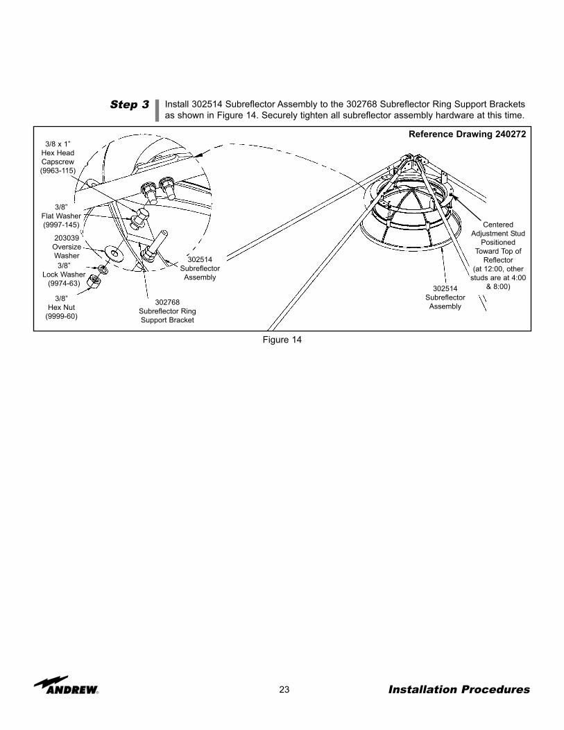
Step 3 Install 302514 Subreflector Assembly to the 302768 Subreflector Ring Support Bracketsas shown in Figure 14. Securely tighten all subreflector assembly hardware at this time.
Figure 14
3/8”Flat Washer(9997-145)
3/8 x 1”Hex HeadCapscrew(9963-115)
203039OversizeWasher3/8”
Lock Washer(9974-63)
3/8”Hex Nut
(9999-60)
302768Subreflector RingSupport Bracket
302514SubreflectorAssembly
302514SubreflectorAssembly
Reference Drawing 240272
CenteredAdjustment Stud
PositionedToward Top of
Reflector(at 12:00, other
studs are at 4:00& 8:00)
Pedestal GroundMount Assembly
PedestalInstallation
Step 1
Step 2
24
The pedestal mount is an elevation-over-azimuth mount optimized for geostationary satelliteapplications. The mount enables continuous elevation adjustment from 0 to 90°. Theazimuth axis has 360° of travel with 40° (±20°) of continuous travel at each adjustment posi-tion. The azimuth lug can be positioned every 30° around the pedestal tube. Follow the sub-sequent procedures for proper installation of pedestal ground mount assembly.
All galvanized ground mount hardware is type A325. Lubricate all A325 bolt threads withsupplied stick wax. Note: Do not tighten hardware until ground mount installation iscomplete unless otherwise instructed.
Place leveling nuts and washers on foundation anchor bolts as shown in Figure 15.
Installation Procedures
Figure 15
202142AnchorBolts
Leveling Nuts (9999-182)and Washers (9997-229)
Foundation
Reference Drawing 240287
Step 3
25
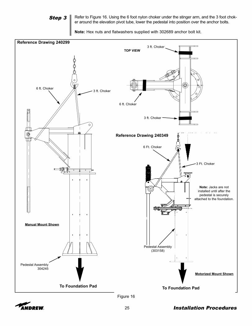
Refer to Figure 16. Using the 6 foot nylon choker under the stinger arm, and the 3 foot chok-er around the elevation pivot tube, lower the pedestal into position over the anchor bolts.
Note: Hex nuts and flatwashers supplied with 302689 anchor bolt kit.
Installation Procedures
Figure 16
3 ft. Choker6 ft. Choker
Reference Drawing 240299
To Foundation PadTo Foundation Pad
6 Ft. Choker
3 Ft. Choker
Pedestal Assembly(303158)
Reference Drawing 240349
Manual Mount Shown
Motorized Mount Shown
Note: Jacks are notinstalled until after thepedestal is securely
attached to the foundation.
Pedestal Assembly304245
TOP VIEW3 ft. Choker
3 ft. Choker
6 ft. Choker
Step 4
Step 5
26
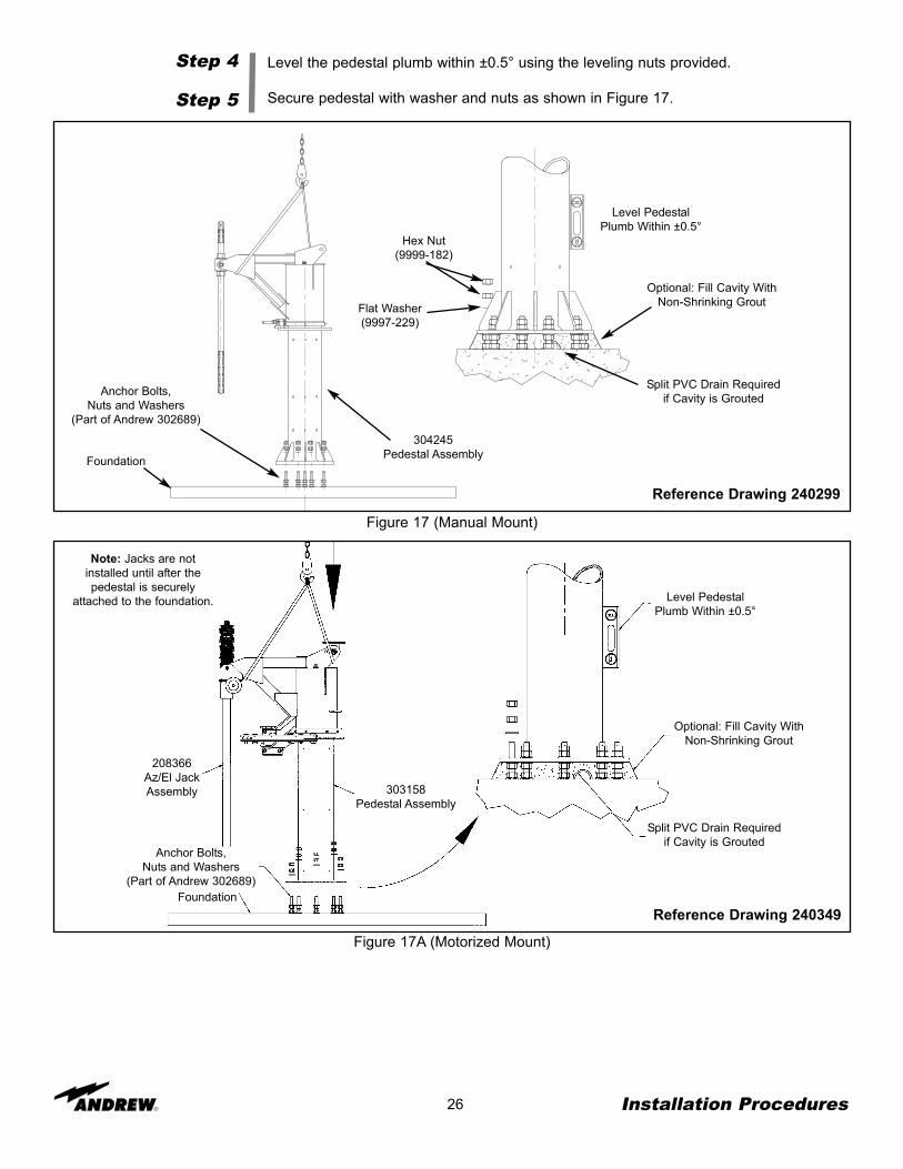
Level the pedestal plumb within ±0.5° using the leveling nuts provided.
Secure pedestal with washer and nuts as shown in Figure 17.
Installation Procedures
Figure 17 (Manual Mount)
304245Pedestal AssemblyFoundation
Anchor Bolts,Nuts and Washers
(Part of Andrew 302689)
Level PedestalPlumb Within ±0.5°
Optional: Fill Cavity WithNon-Shrinking Grout
Split PVC Drain Requiredif Cavity is Grouted
Hex Nut(9999-182)
Flat Washer(9997-229)
Reference Drawing 240299
Figure 17A (Motorized Mount)
Anchor Bolts,Nuts and Washers
(Part of Andrew 302689)Foundation
303158Pedestal Assembly
Optional: Fill Cavity WithNon-Shrinking Grout
Level PedestalPlumb Within ±0.5°
Split PVC Drain Requiredif Cavity is Grouted
Reference Drawing 240349
208366Az/El JackAssembly
Note: Jacks are notinstalled until after thepedestal is securely
attached to the foundation.
Step 6(Motorized Mount
Only)
27 Installation Procedures
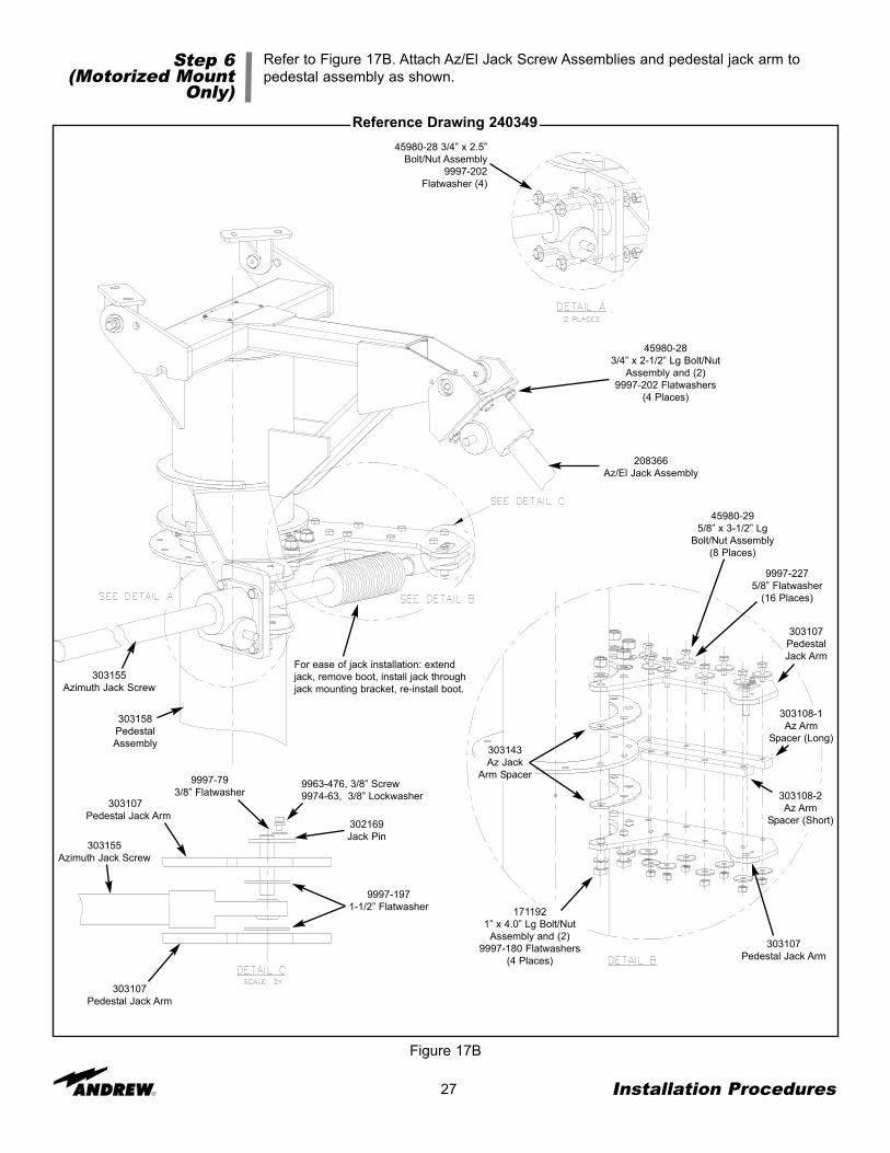
Refer to Figure 17B. Attach Az/El Jack Screw Assemblies and pedestal jack arm topedestal assembly as shown.
Figure 17B
303155Azimuth Jack Screw
208366Az/El Jack Assembly
303158PedestalAssembly
45980-283/4” x 2-1/2” Lg Bolt/Nut
Assembly and (2)9997-202 Flatwashers
(4 Places)
303143Az Jack
Arm Spacer
1711921” x 4.0” Lg Bolt/Nut
Assembly and (2)9997-180 Flatwashers
(4 Places)
303108-1Az Arm
Spacer (Long)
303108-2Az Arm
Spacer (Short)
45980-295/8” x 3-1/2” Lg
Bolt/Nut Assembly(8 Places)
303107PedestalJack Arm
9997-2275/8” Flatwasher
(16 Places)
303107Pedestal Jack Arm
303107Pedestal Jack Arm
303107Pedestal Jack Arm
303155Azimuth Jack Screw
9997-1971-1/2” Flatwasher
302169Jack Pin
9963-476, 3/8” Screw9974-63, 3/8” Lockwasher
9997-793/8” Flatwasher
Reference Drawing 24034945980-28 3/4” x 2.5”
Bolt/Nut Assembly9997-202
Flatwasher (4)
For ease of jack installation: extendjack, remove boot, install jack throughjack mounting bracket, re-install boot.
Reflector toGround Mount
Assembly
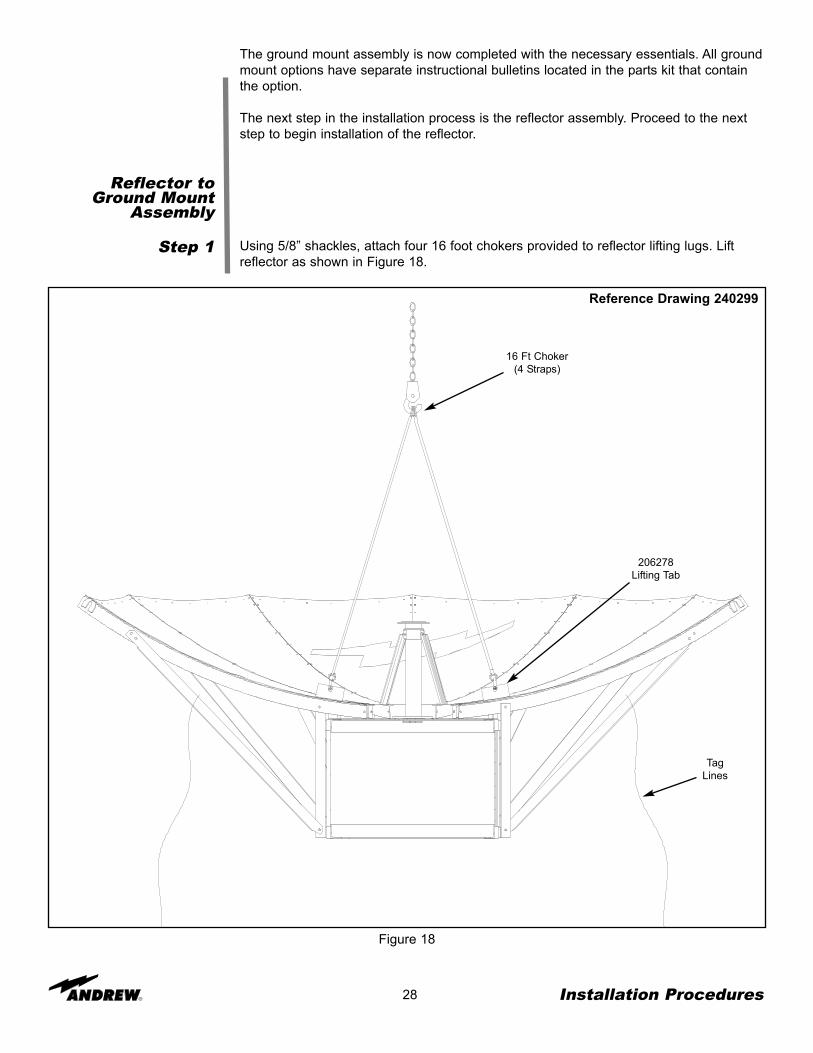
Step 1
28 Installation Procedures
Using 5/8” shackles, attach four 16 foot chokers provided to reflector lifting lugs. Liftreflector as shown in Figure 18.
Figure 18
16 Ft Choker(4 Straps)
TagLines
206278Lifting Tab
Reference Drawing 240299
The ground mount assembly is now completed with the necessary essentials. All groundmount options have separate instructional bulletins located in the parts kit that containthe option.
The next step in the installation process is the reflector assembly. Proceed to the nextstep to begin installation of the reflector.
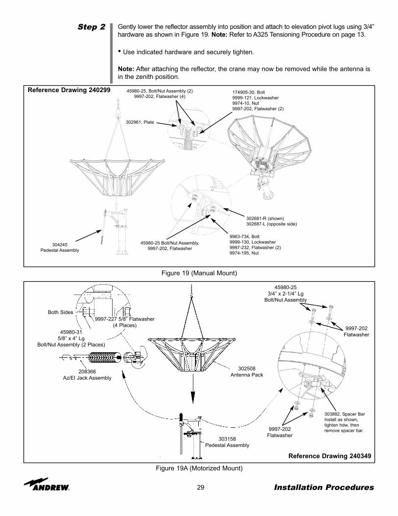
Step 2
29 Installation Procedures
Gently lower the reflector assembly into position and attach to elevation pivot lugs using 3/4”hardware as shown in Figure 19. Note: Refer to A325 Tensioning Procedure on page 13.
• Use indicated hardware and securely tighten.
Note: After attaching the reflector, the crane may now be removed while the antenna isin the zenith position.
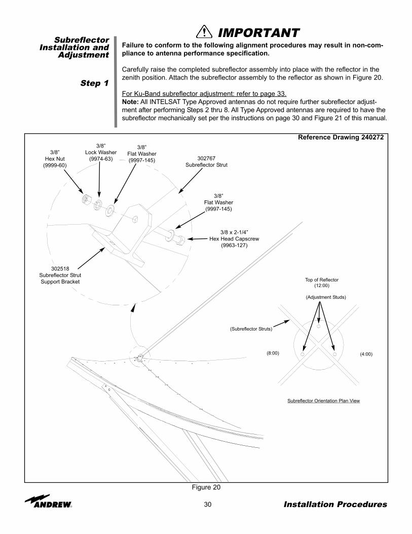
Failure to conform to the following alignment procedures may result in non-com-pliance to antenna performance specification.
Carefully raise the completed subreflector assembly into place with the reflector in thezenith position. Attach the subreflector assembly to the reflector as shown in Figure 20.
For Ku-Band subreflector adjustment: refer to page 33.Note: All INTELSAT Type Approved antennas do not require further subreflector adjust-ment after performing Steps 2 thru 8. All Type Approved antennas are required to have thesubreflector mechanically set per the instructions on page 30 and Figure 21 of this manual.
3/8”Hex Nut
(9999-60)
3/8”Lock Washer
(9974-63)
3/8”Flat Washer(9997-145) 302767
Subreflector Strut
3/8 x 2-1/4”Hex Head Capscrew
(9963-127)
3/8”Flat Washer(9997-145)
302518Subreflector StrutSupport Bracket
Reference Drawing 240272
IMPORTANT
Subreflector Orientation Plan View
Top of Reflector(12:00)
(Adjustment Studs)
(8:00) (4:00)
(Subreflector Struts)
31 Installation Procedures
Step 2
Step 3
Step 4
Step 5
Reference the appropriate feed installation drawing and install the feed system assembly.Note: The feed installation instructions are packaged as part of the feed system kit.
Adjust the height of the subreflector with the 302752-( ) Subreflector Setting Rod. Restthe square end of the setting rod on top of the first panel seam screw. Choose a screwwhich is nearest one of the subreflector adjustment threaded rods. Refer to Figure 22 forthreaded rod adjustment locations.Sweep the setting rod back and forth across the edge of the subreflector to find theshortest distance. Adjust the height of the subreflector to within 1/32” (1 mm) of the set-ting rod.
Center the subreflector using dimension “A”. Refer to Figure 22 for subreflector center-ing adjustment hardware location. Note: For C-Band Feeds: dimension “A” should betaken from the edge of the feed horn to the subreflector edge. For Ku-Band Feeds:dimension “A” should be taken from the edge of the subreflector to the mounting bolt.Perform this measurement at 4 locations (Top, Bottom, Left and Right).
Sweep tape measure back and forth across the subreflector edge using the shortest dis-tance as dimension “A”. Note: Dimension “A” should not vary more than 1/16” (1.5 mm) ateach of the four measurement positions.
Figure 21
302752SubreflectorSetting Rod
Rest the Setting Rod onTop of First Seam Screw
Reference Drawing 240272
`A’(C-band)
Feed HornAssembly
Ku-Band Setting Rod
C-Band Setting Rod
70-3/4”
71”Screw OnAluminum
Tip
Setting Rod Types
`A’(Ku-band)
32 Installation Procedures
Step 6
Step 7
Step 8
Re-check subreflector centering and height settings.
Remove and store 206278 lifting tabs. Replace panel seam hardware at lifting tab loca-tions.
Final Subreflector Settings should be performed with antenna either in operating posi-tion or a nominal 30° elevation angle.
After you have completed the assembly of your antenna, you are now ready to becomeoperational. In order to operate the earth station antenna, you will need to direct it to thedesired satellite adjusting both the elevation and azimuth angles appropriately. The fol-lowing procedures provide details on how to correctly position your antenna on thedesired satellite.
Subreflector CenteringAdjustment Hardware
(3 Places)
Reference Drawing 240272
Figure 22
Threaded RodAdjustment Location
(3 Places)
On a manual mount, tighten all mount hardware (Figure 16) after desired satellite hasbeen aquired.
Overview
Acquiring ASatellite
33 Operation
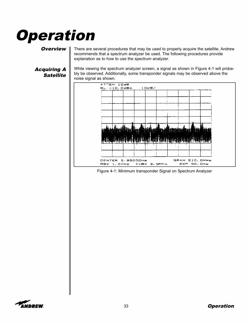
There are several procedures that may be used to properly acquire the satellite. Andrewrecommends that a spectrum analyzer be used. The following procedures provideexplanation as to how to use the spectrum analyzer.
While viewing the spectrum analyzer screen, a signal as shown in Figure 4-1 will proba-bly be observed. Additionally, some transponder signals may be observed above thenoise signal as shown.
Operation
Figure 4-1: Minimum transponder Signal on Spectrum Analyzer
Step 1
Step 2
Step 3
Step 4
Step 5
Step 6
34
The following steps provide the procedure for acquiring a satellite.
Begin by obtaining the correct Az/El pointing data for the satellite of interest based onspecific calculations for this particular site.
Using an inclinometer placed on the enclosure drum surface, position the antenna to thespecified elevation angle.
Manually move the antenna in the azimuth (scanning back-and-forth around the direc-tion of the specified azimuth angle) to achieve the maximum (greatest amplitude)transponder signals.
• Scan in one direction until the amplitude continues to diminish and then scan in theopposite direction until the same condition occurs.
• Return to the position yielding the greatest amplitude.
The maximum azimuth excursion from the original setting should not exceed plus orminus 1.5 degrees or the antenna may begin to access a different satellite.
With the antenna positioned in azimuth such that the transponder signals are maxi-mized, follow the same procedure manually moving the antenna in elevation (scanningup-and-down) to further maximize the transponder signals.
Repeat this procedure alternating between the azimuth and elevation excursions of theantenna to peak the transponder signal amplitude.
With the antenna peaked in azimuth and/or elevation, check to see if you’re peaked ona sidelobe. Move the antenna in azimuth while observing the spectrum analyzer screen.Refer to Figure 4-2.
Figure 4-2: Antenna Radiation Pattern Topographical Diagram with Plan View
Operation
Step 7
Step 8
Step 9
35
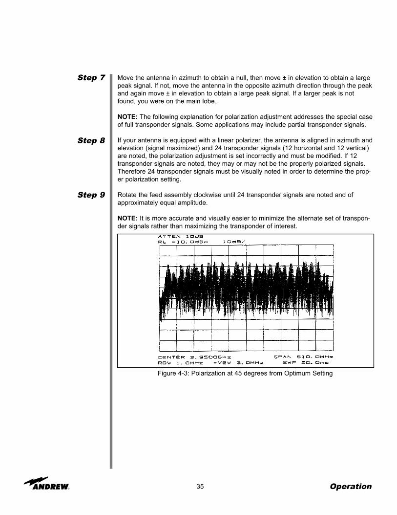
Move the antenna in azimuth to obtain a null, then move ± in elevation to obtain a largepeak signal. If not, move the antenna in the opposite azimuth direction through the peakand again move ± in elevation to obtain a large peak signal. If a larger peak is notfound, you were on the main lobe.
NOTE: The following explanation for polarization adjustment addresses the special caseof full transponder signals. Some applications may include partial transponder signals.
If your antenna is equipped with a linear polarizer, the antenna is aligned in azimuth andelevation (signal maximized) and 24 transponder signals (12 horizontal and 12 vertical)are noted, the polarization adjustment is set incorrectly and must be modified. If 12transponder signals are noted, they may or may not be the properly polarized signals.Therefore 24 transponder signals must be visually noted in order to determine the prop-er polarization setting.
Rotate the feed assembly clockwise until 24 transponder signals are noted and ofapproximately equal amplitude.
NOTE: It is more accurate and visually easier to minimize the alternate set of transpon-der signals rather than maximizing the transponder of interest.
Figure 4-3: Polarization at 45 degrees from Optimum Setting
Operation
Step 10
36
With all 24 transponder signals of approximately equal amplitude appearing on thespectrum analyzer screen determine the specific antenna system and satellite parame-ters. Rotate the feed assembly as required until the appropriate (odd or even) transpon-der signals are maximized.
Figure 4-4: Maximizing Odd Transponders
Figure 4-5: Optimum Polarization Setting
Operation
SubreflectorAdjustment
37 Operation
After the satellite has been acquired and testing has taken place with the spectrum ana-lyzer, the subreflector may need to be adjusted to maximize optimum performance ofyour antenna. The following procedures should be followed if a subreflector adjustmentis required to maximize optimum performance.
NOTE: All INTELSAT Type Approved antennas do not require subreflector adjustmentupon completion of mechanical adjustments referenced on pages 30 and 31.
Before proceeding, azimuth and elevation patterns should be conducted to determinethe adjustments that need to be made. The goal is to achieve a high peak on the mainlobe and even distances between the main lobe and sidelobes.
NOTE: No adjustments should be made in the receive band.
If your pattern dictates a need to adjust the azimuth angle(the left sidelobe requiresadjustment), the west side (northern hemisphere) of the subreflector should be adjustedoutward by loosening the screws on the subreflector and adjusting the left side (northernhemisphere) outward. An easy way to remember this adjustment feature is through theacronym WOLD (West Out Left Down).
If your pattern dictates a need to adjust the elevation angle(the right sidelobe requiresadjustment), the bottom side of the subreflector should be adjusted downward by loos-ening the screws between the subreflector and the struts and adjusting the bottom sideof the subreflector downward. An easy way to remember this adjustment is through theacronym BOLD (Bottom Out Left Down).
Each of these adjustments should be repeated until each sidelobe is of equal distancefrom the peak of the mainlobe.
After the BOLD and WOLD adjustments have been made, it may be necessary to adjustthe main lobe. The goal is to achieve a high null depth (distance between lower inter-section of sidelobes and top of main lobe) as shown in Figure 4-5.
In order to adjust the main lobe pattern characteristics ALL subreflector adjustmentscrews should be adjusted at the same degree (Note: Because the azimuth and eleva-tion adjustments have been set, it is very important that the null depth adjustment becarefully conducted. Be careful not to alter any previous adjustments that have beenmade to the subreflector. Follow the procedure listed below when adjusting the nulldepth of the main lobe.
C-band feeds - Adjustment screws are 3/4 x 10. Move 1 turn per 1 dB of imbalance.
Ku-band feeds - Adjustment screws are 1/4 x 20. Move 1 turn per 1 dB of imbalance.
All adjustments should be continued until the desired pattern is achieved. Upon comple-tion the antenna should be properly aligned with the satellite for maximum performance.
Overview
General Cleaning
Electrical Parts
38 Preventive Maintenance
This section contains periodic preventive maintenance instructions for the 4.9-MeterEarth Station Antenna. Included in this section are inspection and preventive mainte-nance procedures including cleaning and lubrication, painting, and an operational volt-age/current checkout procedure deemed within the capabilities of the average stationtechnician. Refer to applicable vendor manuals for any repair procedures not included inthis section yet designated as capable off being performed in the “field” rather thanrequiring specialized facilities, tools, and/or test equipment as well as technically trainedpersonnel.
An operational checkout procedure provides an accurate indication of the overall earthstation performance and should be performed at intervals of approximately threemonths. This procedure is essentially performed during the various modes of normaloperation of the earth station. In addition, the operational checkout procedure should beperformed after any repairs or adjustments have been made, or whenever the earth sta-tion is suspected of degraded operation. If any discrepancy in performance exists andthe condition cannot be readily remedied to return the earth station to a proper operatingcondition, the appropriate troubleshooting procedures should be referenced to locate thefault. After the trouble is determined and the repairs affected, a final operational check-out procedure should be performed to verify that all discrepancies have been corrected.
The following paragraphs describe the inspection and preventive maintenance proce-dures for the earth station. These instructions include general cleaning and inspection,the preservation of metal parts and lubrication. Periodic replacement of assemblies orcomponents as a preventive measure is not required. Malfunctions of the earth stationcan be traced to components, assemblies, and parts through the use of applicable trou-bleshooting procedures.
To prevent the excessive accumulation of dust and dirt as well as the removal of suchcontaminants, thoroughly clean the equipment whenever visually inspecting the earthstation components. No special cleaning procedures are required. However, a thoroughcleaning in accordance with the following procedures is required to assure continuedtrouble-free operation.
Minor cleaning, such as the removal of dust and loose foreign particles can be accom-plished by one of the following:
• Vacuuming
• Using a soft brush or lint-free cloth
• Blowing out the dust and dirt with low pressure (5 to 25 psi), dry compressed air
When using air to blow off the contaminants, either avoid or be careful when directingthe air stream on delicate parts. To remove imbedded dirt, grease, or oil from electricalparts; use a 50 percent solution of isopropyl (rubbing) alcohol and apply with a soft bris-tle brush. It may be necessary to brush some parts vigorously with a stiff bristle brush toremove imbedded and hardened dirt particles. If possible, avoid excessive use of clean-ing solvent on electrical insulation. After cleaning, allow the cleaned parts to dry for 10 to15 minutes before placing the equipment into operation.
Preventive Maintenance
Mechanical Parts
Inspection
Antenna
39
Clean mechanical parts by first removing dust, dirt, and other loose contaminants with ascraper, stiff brush (bristle or wire in the case of rust or other corrosion), or cloth or com-pressed air at 25 to 40 psi. Any accumulated imbedded dirt, corrosion, grease, or oildeposits that require further cleaning may be removed with a bristle or wire brush and acleaning solvent such as trichlorethylene or equal. After cleaning, allow cleaned parts todry for 10 to 15 minutes before placing the equipment into operation.
The frequency of inspection is contingent upon the user’s individual standards and theoperational environment in which the earth station is located. However, a visual inspec-tion of the earth station components should be performed at least semi-annually. Wherethere are no established wear limits, perform a visual inspection to locate worn or dam-aged parts which could cause improper functioning of the earth station. It is recommend-ed that the mechanical and electrical inspection be performed on the assembled or par-tially disassembled equipment to determine the extent of disassembly required prior tocompletely disassembling a suspected malfunctioning component or module. In theabsence of any special inspection requirements, operational tests are the most effectivemeans in isolating parts and assemblies requiring further inspection. Any conditionnoted during inspection that may preclude continued proper operation of the earth sta-tion prior to the next scheduled inspection should be noted. The discrepant conditionshould be corrected (repaired or replaced) immediately or at the conclusion of theinspection procedure.
Inspection of the antenna conforms generally to standard visual inspection proceduresperformed on electromechanical equipment. In addition to these procedures, performthe following checks and visual inspections for the specific conditions noted:
• Inspect all wiring and cables particularly the network to enclosure and enclosure tomount interfaces for discoloration and burned insulation, moisture entry, corrosion, dirt,breaks, security of connection, and other signs of deterioration. Examine connections fordirt, corrosion, and mechanical defects. Check for loose or broken lacing and cut, abrad-ed, frayed, brittle, and cracked insulation.
• Examine connectors for corrosion, broken inserts and stripped threads. Check con-nector shells for distortion and dents, and contact pins for bends, misalignment or otherdeformities. Check connector inserts for cracks, and carbon tracking, burns or charringindicating arc-over.
• Check all electrical component for dirt, cracks, chips, breaks, discoloration, and othersigns of deterioration and damage. A discolored, blistered, or burnt condition is evidenceof overload.
• Inspect the azimuth and elevation jackscrew boots for security of attachment at bothends, for abrasion, tears, cuts, brittleness and other damage that may expose thejackscrew to the environment (water, dust, etc.). Minor repairs can be made with RTV-108 silicone rubber sealant.
Preventive Maintenance
40
• Visually inspect the feed window for dirt and the feed, feed supports, feed window,and reflector for distortion, foreign object damage and environmental deterioration dueto ice and snow, dust, rain, hail, and high winds, etc. which may cause electrical compo-nent and/or structural deformation.
• Check the cable attachment to the resolvers and to the LNA or LNB’s and enclosuremount interface for security, the cable rouging for secure hanger attachment and thecable insulation for cuts, cracking, abrasion, and other deterioration. Check the LNA orLNB’s and the resolvers for a secure mechanical attachment. Ensure proper torquing ofpolarization drive gear box setscrews and appropriate tensioning of corresponding drivechain assembly, if applicable.
• Check (if applicable) that the drain holes in the bottom of the enclosure are notobstructed and there is no evidence of water accumulation. Check the enclosure doorsfor proper closure and that the door seals are intact, not torn, abraded or otherwisedamaged. Check that all other seals are intact and if not, use a coating of RTV-108 (sili-cone rubber sealant) to seal any exposed electrical fitting, bolt hold, or other possiblewater entry to electrical components in order to maintain a weatherproof condition. If theenclosure is provided with a vent fan, check for free operation of the fan blade. The fanbearings are permanently lubricated; any binding, abnormal noise or vibration necessi-tates replacement of he fan assembly. Check and replace the fan filter element if itappears dirty or obstructed with dust.
• Visually inspect all mechanical parts for freedom of operation with no misalignment,binding or interference. Check all cabling for sufficient slack to prevent cable strain aswell as adequate restraint to prevent abrasion or chaffing during antenna and feedmovement.
• Check security of antenna mounting and interconnecting assembly hardware. Be cer-tain all electrical grounding connections (including cross-axis grounding straps) areintact and secure, not corroded or broken. Thoroughly clean any noticeable corrodedportions of grounding cables, unplated portion of universal terminals and correspondingmounting surfaces using a wire brush. Replace rather than tighten any loose A325structural hardware. The hardware distorts at initial installation and once loosened willnot maintain the required high strength friction connection. All other assembly and instal-lation hardware should be tightened to its original torqued condition. When installingnew structural hardware, do not use a wrench with a lever arm longer than two feet.
• Examine painted aluminum and galvanized surfaces and touch-up where required.
Preventive Maintenance
Preservation ofComponent Parts
Aluminum Parts
GalvanizedSurfaces
Lubrication
41
When preserving the component parts, refer to the following paragraphs in this section.
Remove all loose paint and corrosion by scraping, wire brushing, or using steel wool. Ifusing steel wool near the feed window, make sure that none remains on the feed hornwindow. Edges of existing paint can be blended with the metal surface by using a finegrit sandpaper. Wipe the surface to be painted with a soft rag dampened in trichlorethyl-ene, lacquer thinner or equal. Be certain to remove all loose paint, corrosion, imbeddeddirt, grease, and oil deposits or the paint will not adhere to the surface. Lacquer thinnerwill dissolve paint if applied heavily and rubbed vigorously. The reflector may be washedwith plain water if necessary. Do not use bleach, soap solutions, or kerosene as it is dif-ficult to remove the residue. Allow the cleaned surface to dry thoroughly before priming.
Prime the cleaned surface by applying zinc chromate primer. The primer can be appliedwith a brush, roller, or pressurized spray. If necessary, thin the primer with lacquer thin-ner to the proper consistency. Feather primer onto adjacent painted surfaces; Allowprimer to thoroughly dry before applying the finish paint coat.
Paint all RF surfaces, such as the inside of the main reflector and subreflector with areflective white paint. This type of paint disperses light rays, reducing the focusing effectof the sun’s radiation, thereby reducing heat build-up caused by the focused sun’ rayson the feed system. Rear surfaces of the reflector and subreflector may be painted witha flat white enamel paint. The paint can be applied with a brush, roller, or pressurizedspray. If necessary, thin the paint with the appropriate thinner to the proper consistency.Thoroughly paint over the primed surfaces and blend with the existing painted surface.
Remove all loose paint and corrosion by scraping, wire brushing, or using steel wool.Edges of existing paint can be blended with the metal surface by using a fine grit sand-paper. Wipe the surface to be painted with a soft rag dampened in trichlorethylene, lac-quer thinner, or equal. be certain to remove all loose paint, corrosion, imbedded dirt,grease, and oil deposits or the paint will not adhere to the surface. Lacquer thinner willdissolve paint if applied heavily and rubbed vigorously. Do not use bleach, soap solu-tions, or kerosene as it is difficult to remove the residue. Allow the clean surface to drythoroughly before painting.
Paint the cleaned surface with a zing-rich paint. The paint can be applied with a brush,roller, or pressurized spray. If necessary, thin the paint with the appropriate thinner tothe proper consistency. Thoroughly paint over the cleaned surface and blend with theexisting painted surface.
For long life and trouble-free operation be certain not to extend the lubrication schedulebeyond the frequency recommended in the Lubrication Chart. The frequency should beshortened if the antenna is subjected to an adverse environment (e.g., high tempera-ture, extended periods of rainfall, high humidity, dust storms, etc). Any component orpart should immediately be lubricated if during inspection or operation, rough, jarring, orintermittent motion is noted, or if squeaky or other unusual noises are heard. Lubricationis required on all metal-to-metal rolling or sliding parts. Us the lubricants recommended.Do not over lubricate. Over lubrication can often be as damaging as under lubrication.Prior to the application of lubricant to any parts, use a clean cloth and/or bristle brushand remove any old lubricant to prevent an excessive build-up. Be certain to remove
Preventive Maintenance
42 Preventive Maintenance
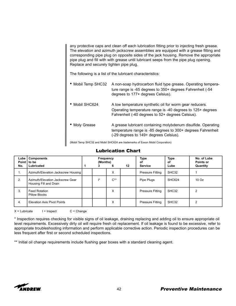
Lube Components Frequency Type Type No. of LubePoint to be (Months) of of Points orNo. Lubricated 1 3 6 12 Service Lube Quantity
1. Azimuth/Elevation Jackscrew Housing X Pressure Fitting SHC32 1
2. Azimuth/Elevation Jackscrew Gear I* C** Pipe Plugs SHC624 10 OzHousing Fill and Drain
3. Feed Rotation X Pressure Fitting SHC32 2Pillow Blocks
4. Elevation Axis Pivot Points X Pressure Fitting SHC32 2
Lubrication Chart
X = Lubricate I = Inspect C = Change
* Inspection requires checking for visible signs of oil leakage, draining replacing and adding oil to ensure appropriate oillevel requirements. Excessively dirty oil will require fresh oil replacement. If oil leakage is found to be excessive, refer toappropriate troubleshooting information and perform applicable corrective action. Periodic inspection procedures can beless frequent after first or second scheduled inspections.
** Initial oil change requirements include flushing gear boxes with a standard cleaning agent.
any protective caps and clean off each lubrication fitting prior to injecting fresh grease.The elevation and azimuth jackscrew assemblies are equipped with a grease fitting andcorresponding pipe plug on opposite sides of the jack housing. Remove the appropriatepipe plug and fill with with grease until lubricant seeps from the pipe plug opening.Replace and securely tighten pipe plug.
The following is a list of the lubricant characteristics:
• Mobil Temp SHC32 A non-soap hydrocarbon fluid type grease. Operating tempera-ture range is -65 degrees to 350+ degrees Fahrenheit (-54 degrees to 177+ degrees Celsius).
• Mobil SHC624 A low temperature synthetic oil for worm gear reducers. Operating temperature range is -40 degrees to 125+ degrees Fahrenheit (-40 degrees to 52+ degrees Celsius).
• Moly Grease A grease lubricant containing molybdenum disulfide. Operating temperature range is -85 degrees to 300+ degrees Fahrenheit (-29 degrees to 149+ degrees Celsius).
(Mobil Temp SHC32 and Mobil SHC624 are trademarks of Exxon Mobil Corporation)