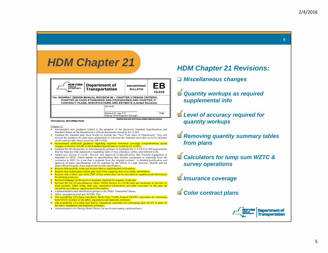
Quantity workups as requiredQuantity workups as required supplemental info
Level of accuracy required for quantity workups
Removing quantity summary tables from plans
Calculators for lump sum WZTC &Calculators for lump sum WZTC & survey operations
Insurance coverage
Color contract plans
2/4/2016
6
6
Quantity Work-Up Changesg
2/4/2016
7
7
Quantity Work-Ups as Supplemental InfoQuantity Work-Ups as Supplemental Info
Now required to be provided as supplemental information to bidders
AdvantagesGives the contractors a better understanding of work expectedGives the contractors a better understanding of work expectedMore confidence in their estimatesLess perceived riskShould result in lower bids
2/4/2016
8
8
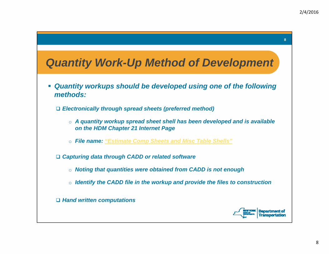
Quantity Work-Up Method of DevelopmentQuantity Work-Up Method of Development
Quantity workups should be developed using one of the following methods:methods:
Electronically through spread sheets (preferred method)
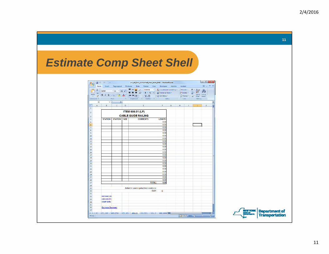
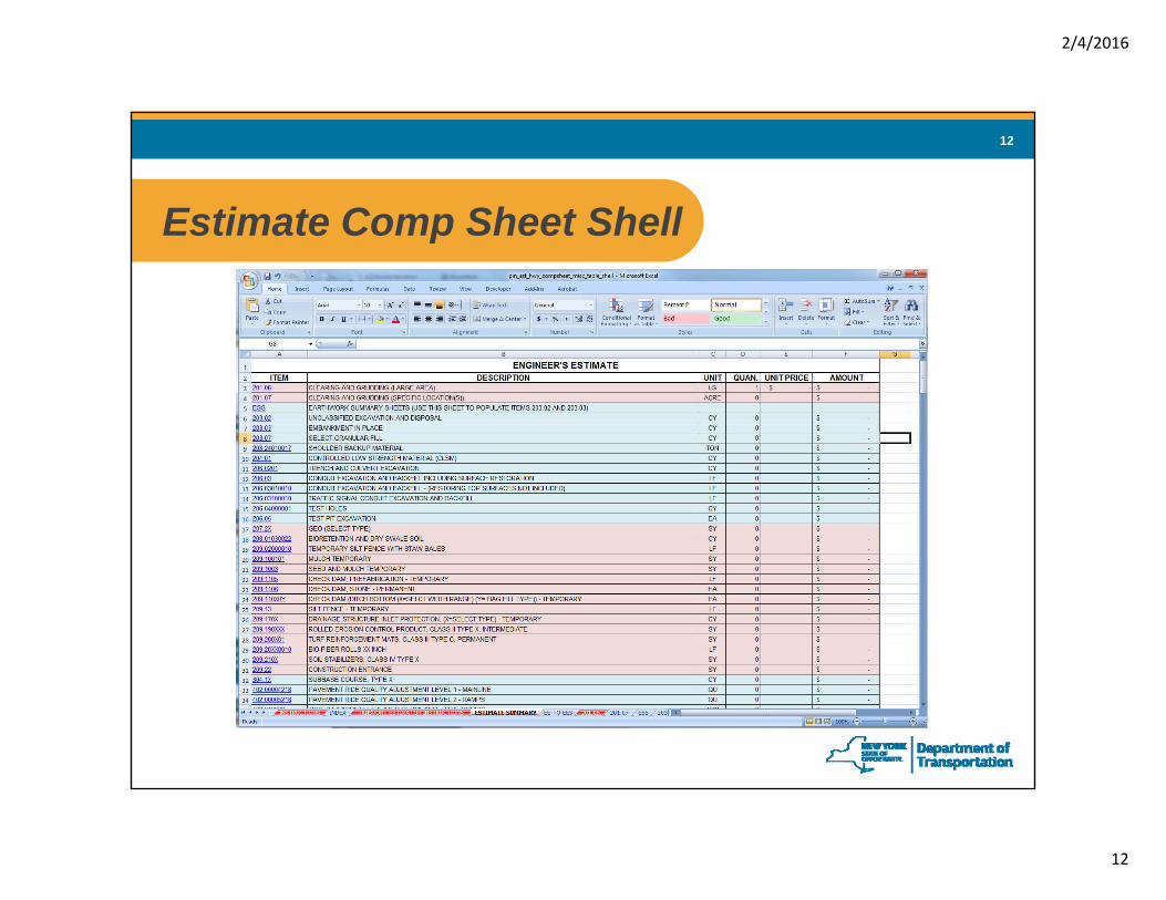
o A quantity workup spread sheet shell has been developed and is available on the HDM Chapter 21 Internet Pageon the HDM Chapter 21 Internet Page
o File name: “Estimate Comp Sheets and Misc Table Shells”
Capturing data through CADD or related softwarep g g
o Noting that quantities were obtained from CADD is not enough
o Identify the CADD file in the workup and provide the files to construction
Quantity Work-Up Level of AccuracyQuantity Work-Up Level of Accuracy
Quantity workups should be developed to an accuracy that allows:
The contractor to properly bid the item
The department to estimate the funds needed for construction
For survey tolerances
Inspectors to verify contractors request for payment
2/4/2016
14
14
List of MiscellaneousTables
2/4/2016
15
15
Revised List of Miscellaneous TablesRevised List of Miscellaneous Tables
Revised list of Misc. Tables that are to be included in the plan setto remove summary only tables and provide them assupplemental information.
Advantages of removing summary tables from the plan set:g g y p
Will decrease the potential of having conflicting information within the plan set.
Since summary tables are typically produced in the quantity workups, it will bel ti i f d i if th d ’t h t t thless time consuming for designers if they don’t have to recreate these sametables in the plan set.
2/4/2016
16
16
Earth Work Summary Sheets
2/4/2016
17
17
Earth Work Summary SheetsEarth Work Summary Sheets
Available on the HDM Chapter 21 Internet PageFile name: “Estimate Comp Sheets and Misc Table Shells”
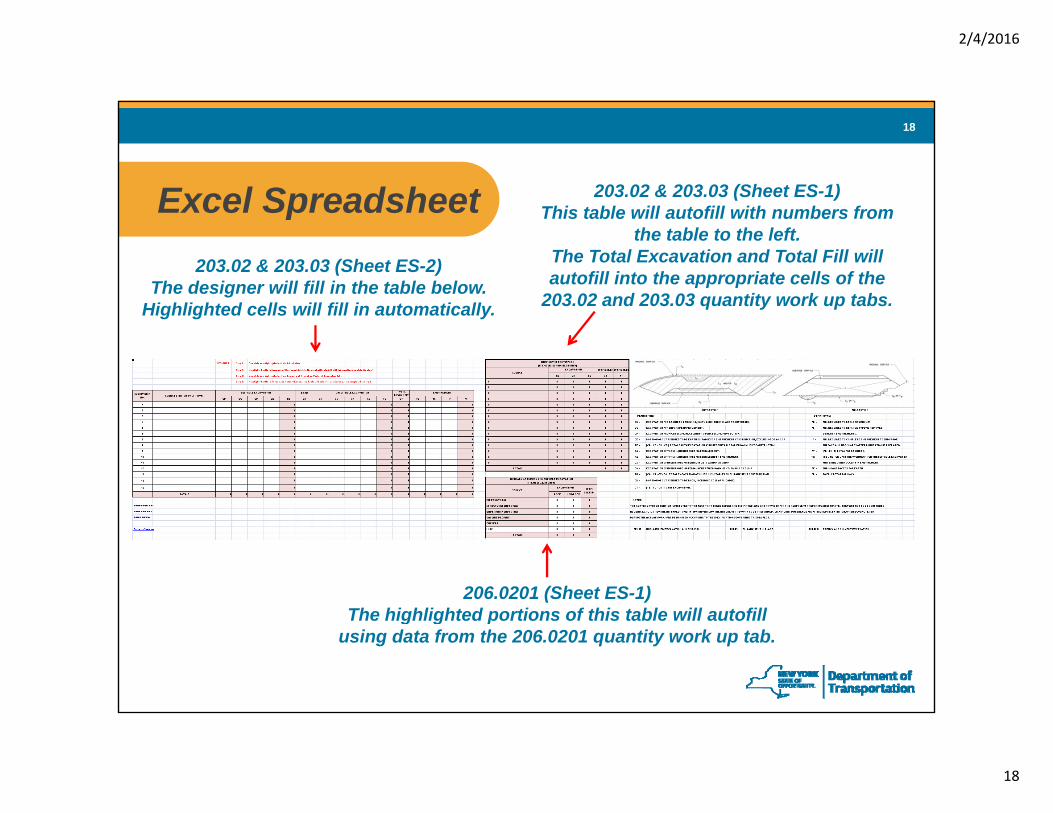
from the 206.0201 quantity work up tab - except for the
Misc. row
2/4/2016
21
21
Exporting to MicroStationExporting to MicroStation
Once tables have been filled out they can be brought into MicroStation usingOnce tables have been filled out they can be brought into MicroStation using the instructions posted on the HDM Chapter 21 internet page.
Sheet ES-2 Sheet ES-1
2/4/2016
22
22
WZTC & Survey OperationsCalculators
2/4/2016
23
23
Spreadsheet for WZTC CalculatorSpreadsheet for WZTC Calculator
Available on the HDM Chapter 21 Internet PageFile name: “Estimate Comp Sheets and Misc Table Shells”File name: Estimate Comp Sheets and Misc Table Shells
Calculator Chart of Recent Bid Results
2/4/2016
24
24
WZTC CalculatorWZTC Calculator Chose a project type:• 1R/2R• 3R• 3R• New & Reconstruction/Intersect.• Bride Replacement/Rehab• Large Culvert
Enter the EES (in the blue cell)Enter the EES (in the blue cell)
Look at each modifier and
Select the appropriate value from the drop down menu
Look at each modifier and its description
The lump sum cost (green cell)is linked to & automatically
t d i t th E i ’entered into the Engineer’s Estimate
2/4/2016
25
25
Chart of Recent Average WZTC BidsChart of Recent Average WZTC BidsCharts to the right of each project type give the average bid results of recent projects based on project type and cost.
Charts are to be used to check the calculator results to ensure valid costs
2/4/2016
26
26
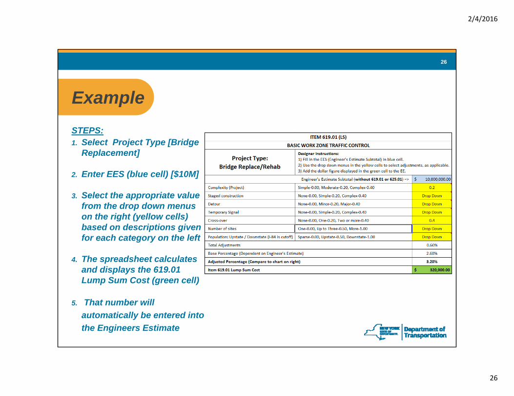
ExampleExampleSTEPS:1. Select Project Type [Bridge
Replacement]
2. Enter EES (blue cell) [$10M]
3. Select the appropriate value3. Select the appropriate value from the drop down menus on the right (yellow cells) based on descriptions given for each category on the left
4. The spreadsheet calculates and displays the 619.01 Lump Sum Cost (green cell)
5. That number will automatically be entered into the Engineers Estimate
2/4/2016
27
27
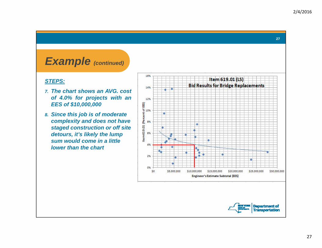
Example ( ti d)Example (continued)
STEPS:
7. The chart shows an AVG. cost7. The chart shows an AVG. costof 4.0% for projects with anEES of $10,000,000
8. Since this job is of moderate complexity and does not have staged construction or off site detours, it’s likely the lump sum would come in a little lower than the chart
2/4/2016
28
28
Identifying Insurance Coverage gRequirements
2/4/2016
29
29
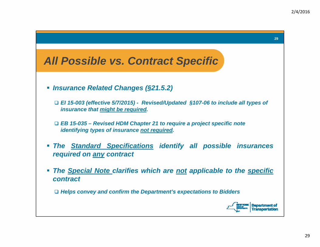
All Possible vs Contract SpecificAll Possible vs. Contract Specific
Insurance Related Changes (§21.5.2)
EI 15-003 (effective 5/7/2015) - Revised/Updated §107-06 to include all types of insurance that might be required.
EB 15-035 – Revised HDM Chapter 21 to require a project specific noteEB 15-035 – Revised HDM Chapter 21 to require a project specific note identifying types of insurance not required.
The Standard Specifications identify all possible insurancesrequired on any contractrequired on any contract
The Special Note clarifies which are not applicable to the specificcontract
Helps convey and confirm the Department’s expectations to Bidders
2/4/2016
30
30
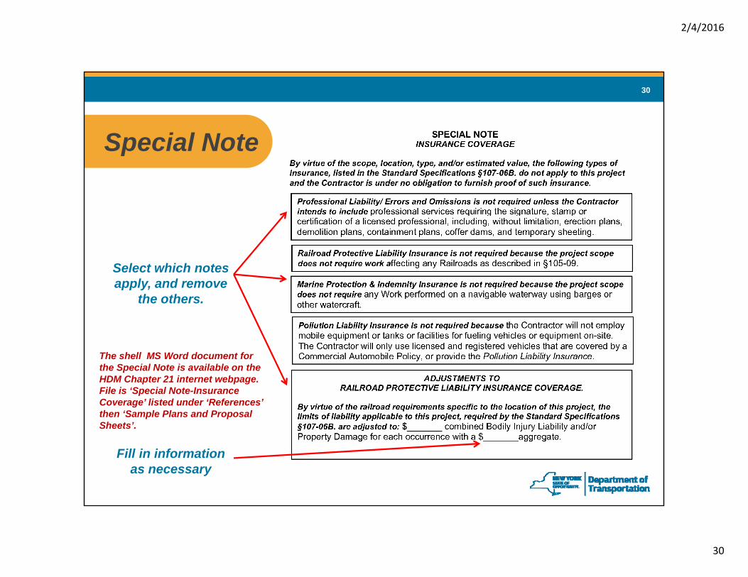
Special NoteSpecial Note
Select which notes apply, and remove pp y,
the others.
The shell MS Word document for the Special Note is available on the HDM Chapter 21 internet webpage. File is ‘Special Note-Insurance Coverage’ listed under ‘References’ then ‘Sample Plans and Proposal Sheets’.
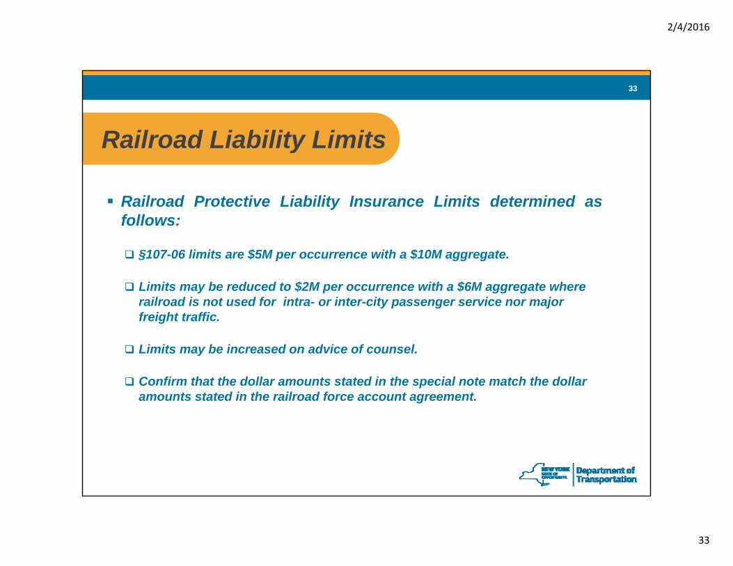
§107-06 limits are $5M per occurrence with a $10M aggregate.
Li it b d d t $2M ith $6M t hLimits may be reduced to $2M per occurrence with a $6M aggregate where railroad is not used for intra- or inter-city passenger service nor major freight traffic.
Limits may be increased on advice of counsel.y
Confirm that the dollar amounts stated in the special note match the dollar amounts stated in the railroad force account agreement.
2/4/2016
34
34
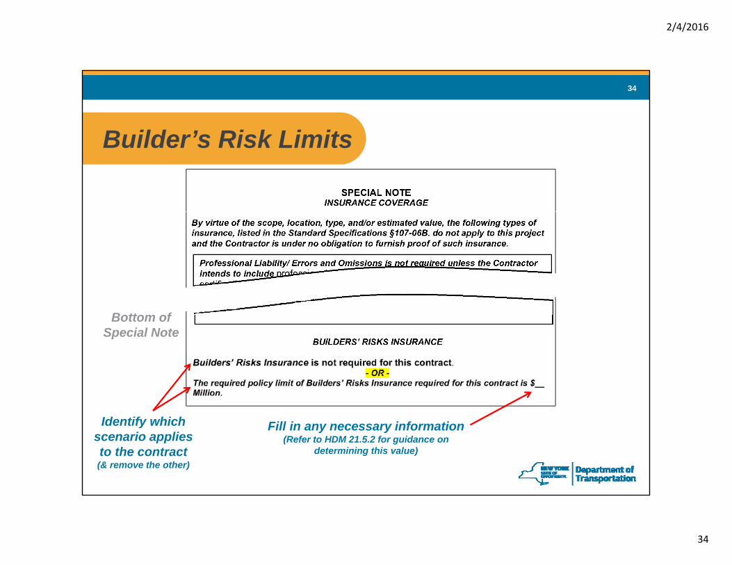
Builder’s Risk LimitsBuilder s Risk Limits
Bottom of Special Note
Identify which Fill in any necessary informationIdentify which scenario applies to the contract(& remove the other)
Fill in any necessary information(Refer to HDM 21.5.2 for guidance on
determining this value)
2/4/2016
35
35
ColorContract Plans
2/4/2016
36
36
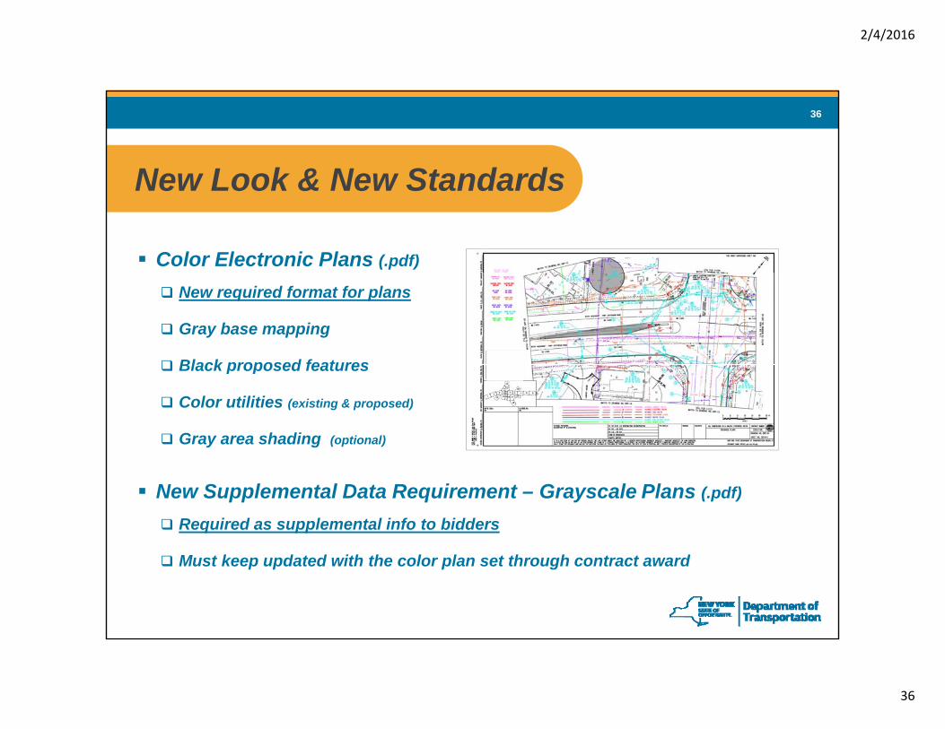
New Look & New StandardsNew Look & New Standards
Color Electronic Plans (.pdf)
New required format for plans
Gray base mapping
Black proposed featuresBlack proposed features
Color utilities (existing & proposed)
Gray area shading (optional)
New Supplemental Data Requirement – Grayscale Plans (.pdf)
Required as supplemental info to bidders
Must keep updated with the color plan set through contract award
2/4/2016
37
37
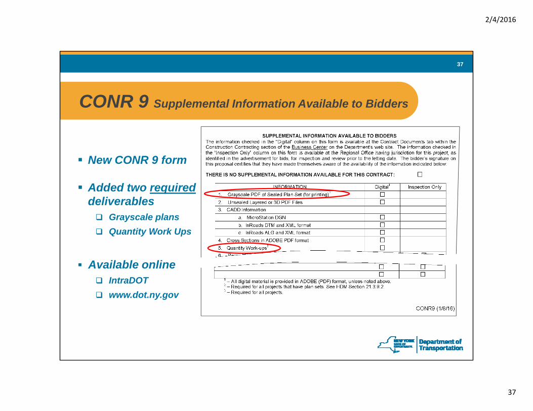
CONR 9 Supplemental Information Available to BiddersCONR 9 Supplemental Information Available to Bidders
New CONR 9 form
Added two requireddeliverables
Grayscale plansQuantity Work Ups
Available onlineIntraDOTwww.dot.ny.gov
2/4/2016
38
38
Why Add Color to PlansWhy Add Color to Plans
Existing Features / Base Mapping - Now displayed as gray
Helps distinguish existing info (gray) from proposed info (black).
Better highlights proposed info.
Utilities (most) - Now displayed as 1 of 7 assigned colors
Improve safety. Reduce cost/delays due to utility conflicts & hits.
H l diff ti t i f l i ll i ‘b ’ ( id lk)Helps differentiate info on plans, especially in ‘busy’ areas (e.g., sidewalk).
2/4/2016
39
39
Utility ColorsUtility Colors
Pink
NYSDOT ColorUnknown
UtilityPink
APWA ColorPink
Red
Purple
Unknown
Electric
Gas / Oil
Pink
Red
Yellow
Orange
Blue
Cyan
Communications
Potable Water
Storm Sewer / Drain Line
Orange
Blue
BlueCyan
Green
N/A
Storm Sewer / Drain Line
Sanitary Sewer
Irrigation / Reclaimed Water
Green
Blue
Purple
Color Variations: Yellow does not display or reproduce well on white backgrounds. For highway work it is helpful todifferentiate between potable water and storm sewer lines.
Note: The American Public Works Association (APWA) uniform color code is theaccepted US industry standard for marking underground utilities in the field.
2/4/2016
40
40
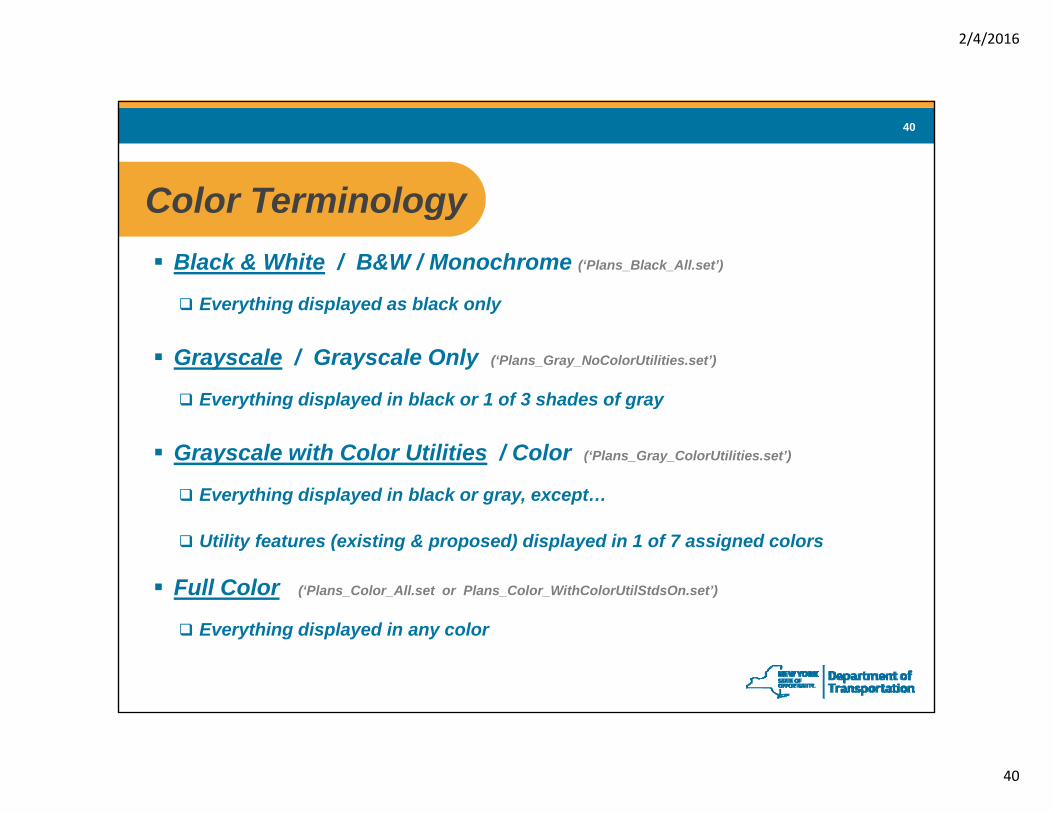
Color TerminologyColor TerminologyBlack & White / B&W / Monochrome (‘Plans_Black_All.set’)
Everything displayed as black onlyEverything displayed as black only
Grayscale / Grayscale Only (‘Plans_Gray_NoColorUtilities.set’)
Everything displayed in black or 1 of 3 shades of grayy g p y g y
Grayscale with Color Utilities / Color (‘Plans_Gray_ColorUtilities.set’)
Everything displayed in black or gray, except…
Utility features (existing & proposed) displayed in 1 of 7 assigned colors
Full Color (‘Plans_Color_All.set or Plans_Color_WithColorUtilStdsOn.set’)
Everything displayed in any color
2/4/2016
41
41
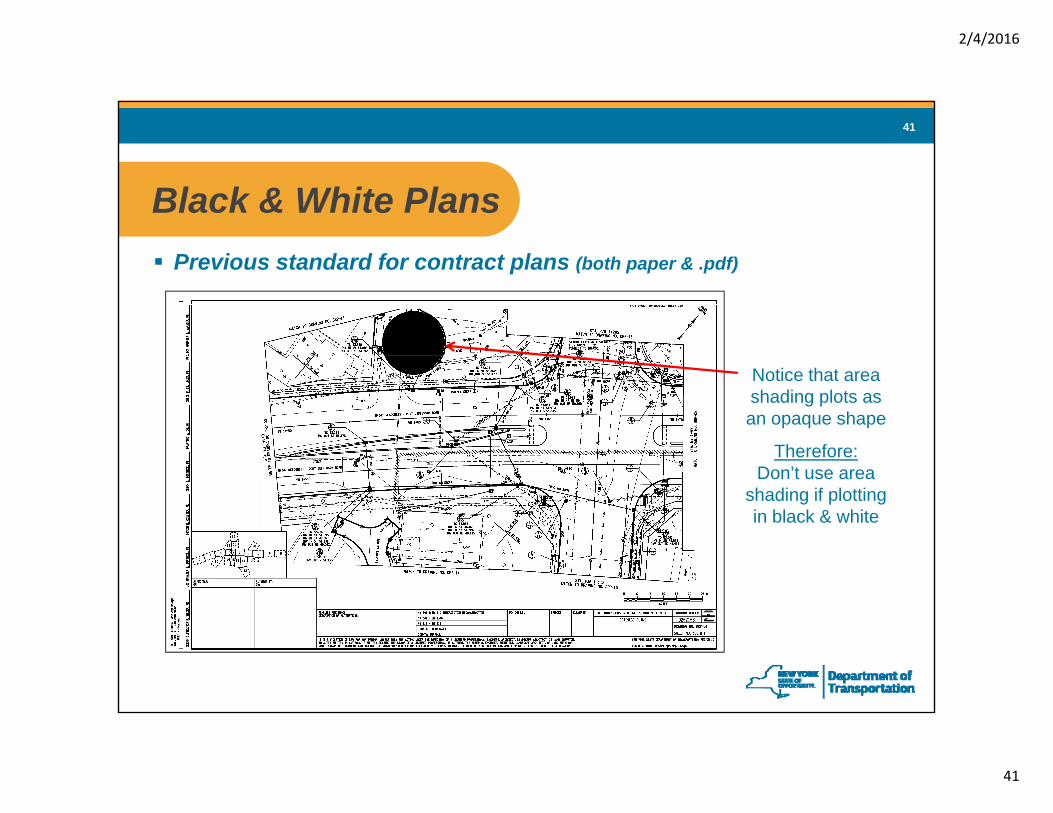
Black & White PlansBlack & White PlansPrevious standard for contract plans (both paper & .pdf)
Notice that area shading plots as an opaque shape
Therefore:Don’t use area
shading if plotting in black & white
2/4/2016
42
42
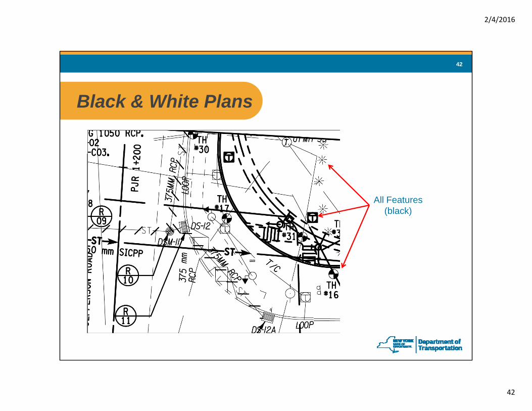
Black & White PlansBlack & White Plans
All Features(black)
2/4/2016
43
43
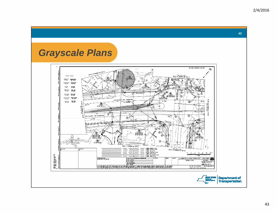
Grayscale PlansGrayscale Plans
2/4/2016
44
44
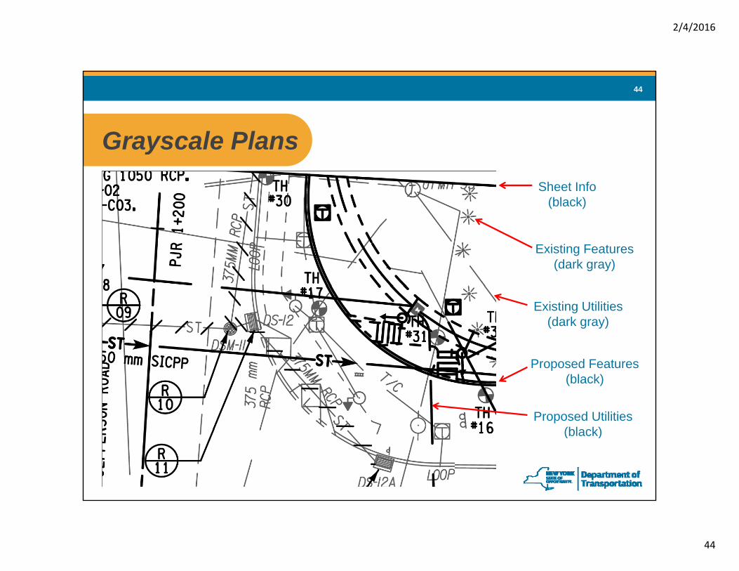
Grayscale PlansGrayscale PlansSheet Info
(black)
Existing Features(dark gray)
Existing Utilities(dark gray)
Proposed Features(black)
Proposed Utilities(bl k)(black)
2/4/2016
45
45
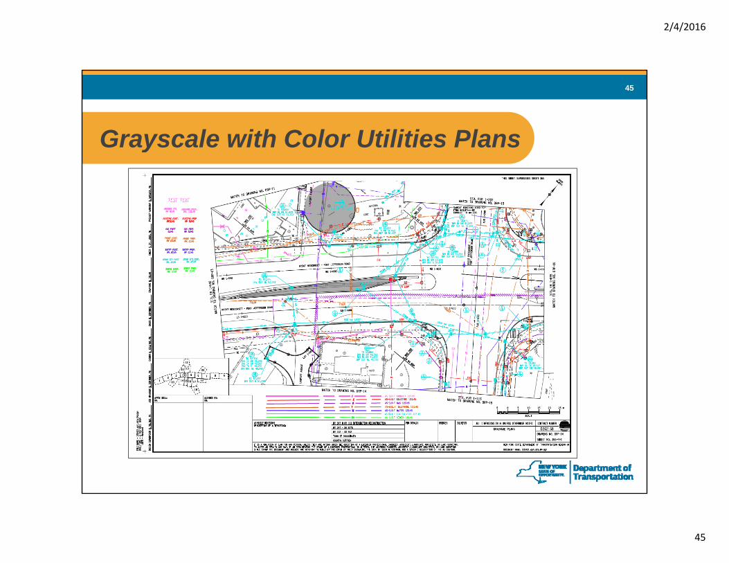
Grayscale with Color Utilities PlansGrayscale with Color Utilities Plans
2/4/2016
46
46
Grayscale with Color Utilities PlansGrayscale with Color Utilities PlansSheet Info
(black)
Existing Features(dark gray)
Existing Utilities(1 of 7 colors)
Proposed Features(black)
Proposed Utilities(1 f 7 l )(1 of 7 colors)
2/4/2016
47
47
Full Color PlansFull Color PlansNot a common format for contract deliverables
Associates specific RGB values to the 256 MicroStation colors
Pen Tables (.pen files)
Assigns specific line thicknesses (mm) to the various MicroStation line weightsCan assign & override many other settings (color, line style, etc.)Can assign different settings to different levels & element types (line or text)Can set priorities as to what levels to display in the background or on topCan override the MicroStation settings and the color table settings
SET Fil.SET FilesWith 1 file a user can set up the color table, pen table, and paper size
Printer Queue Default Setting (Uses a .set file)
Printer specific default settings (color table, pen table & paper size)
2/4/2016
50
50
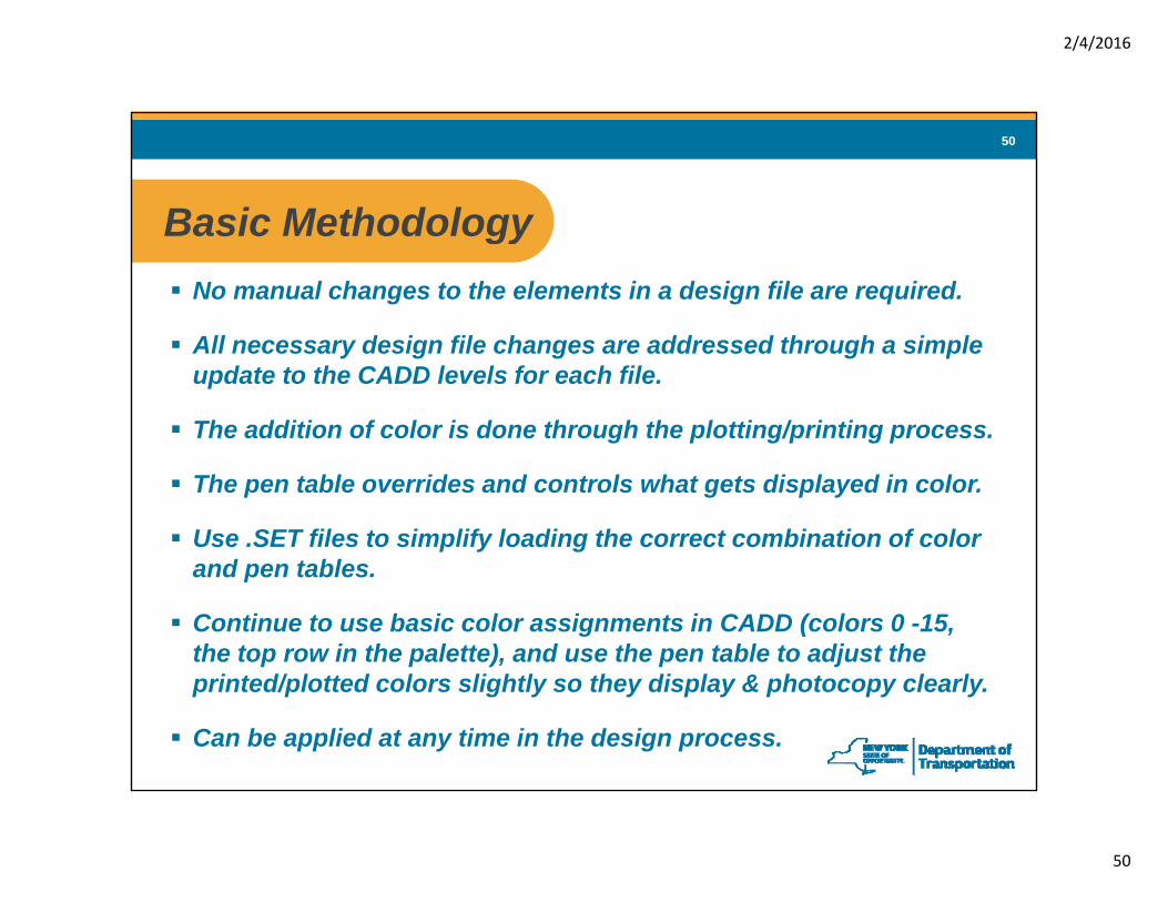
Basic MethodologyBasic MethodologyNo manual changes to the elements in a design file are required.
All d i fil h dd d th h i lAll necessary design file changes are addressed through a simple update to the CADD levels for each file.
The addition of color is done through the plotting/printing process.
The pen table overrides and controls what gets displayed in color.
Use .SET files to simplify loading the correct combination of color and pen tablesand pen tables.
Continue to use basic color assignments in CADD (colors 0 -15, the top row in the palette), and use the pen table to adjust the
i t d/ l tt d l li htl th di l & h t l lprinted/plotted colors slightly so they display & photocopy clearly.
Can be applied at any time in the design process.
2/4/2016
51
51
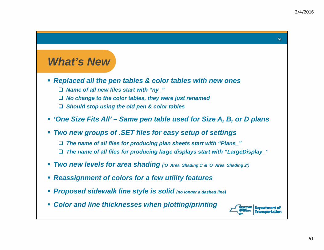
What’s NewWhat s NewReplaced all the pen tables & color tables with new ones
Name of all new files start with “ny_”No change to the color tables, they were just renamedShould stop using the old pen & color tables
‘One Size Fits All’ – Same pen table used for Size A, B, or D plans
Two new groups of .SET files for easy setup of settingsThe name of all files for producing plan sheets start with “Plans_”The name of all files for producing large displays start with “LargeDisplay_”
Two new levels for area shading (‘O_Area_Shading 1’ & ‘O_Area_Shading 2’)
Reassignment of colors for a few utility features
Proposed sidewalk line style is solid (no longer a dashed line)
Color and line thicknesses when plotting/printing
2/4/2016
52
52
New FilesNew FilesColor Tables Pen Tables .SET filesny_color.ctb ny_b_basic.pen Plans_Black_All.set
Note: There are new design library files, but they are named the same as the old files
2/4/2016
53
53
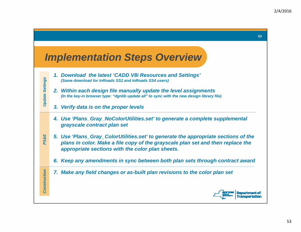
Implementation Steps OverviewImplementation Steps Overview1. Download the latest ‘CADD V8i Resources and Settings’
(Same download for InRoads SS2 and InRoads SS4 users)
tting
s
2. Within each design file manually update the level assignments (In the key-in browser type: “dgnlib update all” to sync with the new design library file)
3. Verify data is on the proper levelsUpd
ate
Set
4. Use ‘Plans_Gray_NoColorUtilities.set’ to generate a complete supplemental grayscale contract plan set
5. Use ‘Plans_Gray_ColorUtilities.set’ to generate the appropriate sections of the plans in color. Make a file copy of the grayscale plan set and then replace the PS
&E
p py g y p pappropriate sections with the color plan sheets.
6. Keep any amendments in sync between both plan sets through contract award
7. Make any field changes or as-built plan revisions to the color plan setion y g p p
Con
stru
cti
2/4/2016
54
54
Step 1 From LANDesk download the latest Step 1 ‘CADD V8i Resources and Settings’
• Loads the new .set, .dgnlib, color tables, and pen tables • Both InRoads SS2 and InRoads SS4 users download the same file• Note: Make sure there are no open Bentley products (MicroStation,
ProjectWise, etc.) when downloading and installing the resources & settings
Computer Desktop Icon
2/4/2016
55
55
Step 2 Within each design file manually update the level Step 2 assignments (from the new design library file which was automatically installed in the correct folder by the ‘Resource & Settings’ update)
• Still necessary even though the .dgnlib file name didn’t change
• In MicroStation, open ‘Utilities’ (or ‘Help’ ) from the top toolbar, & then ‘Key-in’ browser• Type in “dgnlib update all” (or select from menu options) and hit ‘Enter’• To verify: In Level Manager check to see if ‘O_Area_Shading 1’ is now listed
Place a proposed sidewalk feature and it should display as a solid line(Note: ‘O_Area_Shading 1’ will be listed in Level Manager after the setting update, even if the ‘dgnlibupdate all’ function was not run, so it is not a valid test for verifying the level assignments were updated)
• Repeat for all design files (e.g., plot file, main design file, any referenced file, etc.)
• Note: Users may need to request that the Photogrammetry Unit update the referenced base map files for their project
2/4/2016
56
56
Step 3 Verify data is on the proper levelsStep 3 Verify data is on the proper levels
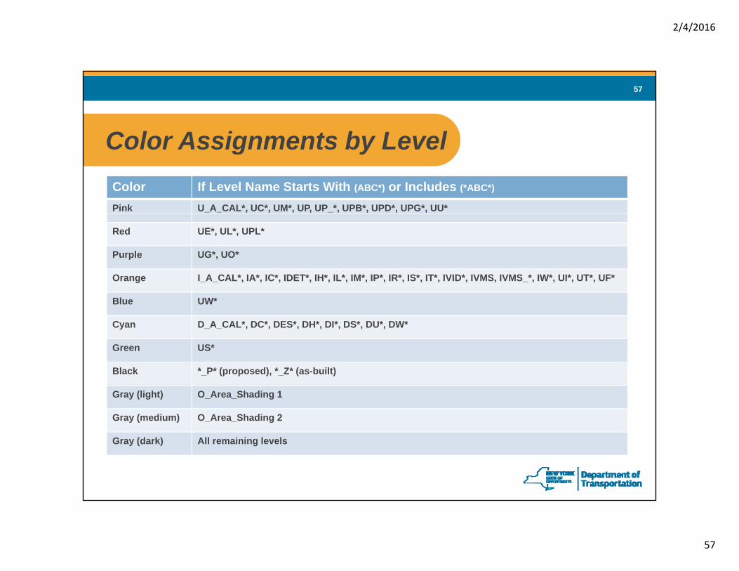
The pen table assigns several attributes and overridesbased on level name.
If data is on the incorrect level it may display improperly (color, etc.)
It is most critical that utility related data be verified to be on the correct level andIt is most critical that utility related data be verified to be on the correct level and that non-utility data is not on the utility levels.
Be aware that the color assignments for a few utility levels will have been changed by the design library update
2/4/2016
57
57
Color Assignments by LevelColor Assignments by LevelColor If Level Name Starts With (ABC*) or Includes (*ABC*)
Step 4 Use Plans_Gray_NoColorUtilities.set to generate a Step 4 complete supplemental grayscale plan set
Complete plan sets are typically the product of combining several sections and subparts each of which are generated from separatesections and subparts each of which are generated from separate InterPlot Organizer .ips files (Example: May have separate .ips files for general plans, typical sections, profiles, misc. tables, structures plans, etc.)
Use the ‘Plans Gray NoColorUtilities.set’ settings file (LoadsUse the Plans_Gray_NoColorUtilities.set settings file (Loads ‘ny_b_gray.pen’ & ‘ny_color.ctb’) to plot all plan sheets.
Combine all the sections & subparts into a collective electronic plan set Note: This may require multiple files/volumes due to file sizeplan set. Note: This may require multiple files/volumes due to file size limitations (75Mb max.).
Apply professional seals (PE stamp) and sheet numbering
Label the grayscale plan set with the suffix “_NoColor”Example: “D263456_R04_Plans_Vol1of5_NoColor.pdf”
2/4/2016
59
59
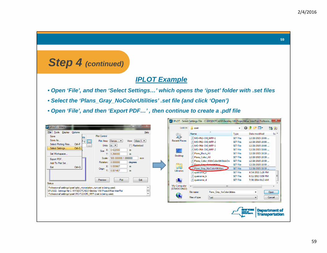
Step 4 (continued)Step 4 (continued)
IPLOT Example• Open ‘File’, and then ‘Select Settings…’ which opens the ‘ipset’ folder with .set files
• Select the ‘Plans_Gray_NoColorUtilities’ .set file (and click ‘Open’)
• Open ‘File’, and then ‘Export PDF…’ , then continue to create a .pdf file
2/4/2016
60
60
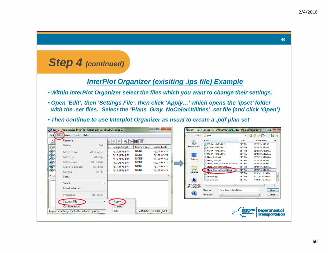
Step 4 (continued)Step 4 (continued)
InterPlot Organizer (exisiting .ips file) Example• Within InterPlot Organizer select the files which you want to change their settings.g y g g
• Open ‘Edit’, then ‘Settings File’, then click ‘Apply…’ which opens the ‘ipset’ folder with the .set files. Select the ‘Plans_Gray_NoColorUtilities’ .set file (and click ‘Open’)
• Then continue to use Interplot Organizer as usual to create a .pdf plan set
2/4/2016
61
61
Step 4 (continued)Step 4 (continued)
InterPlot Organizer (new .ips file) Example
• Open InterPlot Organizer & select the option to create a new plot set, then click ‘OK’, which opens the ‘Create Plots’ dialog box.
• Click ‘Browse…’ for the ‘Settings file name’, which opens the ‘ipset’ dialog box.
• As in the previous example, proceed by selecting from the list of .set files, the ‘Plans_Gray_NoColorUtilities’ .set file (and click ‘Open’)
• Then continue to use InterplotOrganizer as usual to create a .pdf plan set
2/4/2016
62
62
Step 5 Use ‘Plans_Gray_ColorUtilities.set’ to generate the Step 5 appropriate sections of the plans in color. Make a file copy of the grayscale plan set and then replace the appropriate sections with the color plan sheets.
Determine which sections of the plan set are to be plotted in color. This will be the legend sheet and then any plan view plan sheets on which utility information may be displayed (e.g., general plans, WZTC plans, sign location plans, utility & drainage plans, etc.).
Conversely, other types of plan sheets (e.g., tables, details, typical sections, profiles, etc.) would not be required to be plotted in color.
Identify the .ips files used to generate the corresponding grayscaleIdentify the .ips files used to generate the corresponding grayscale version of these plan sheets to be plotted in color, and then for all appropriate plan sheets apply the ‘Plans_Gray_ColorUtilities.set’ settings [see next slide] (Loads ‘ny_b_gray_colorutil.pen’ & ‘ny_color.ctb’).
To ensure consistency between plans sets, it is recommended that the same.ips file that was used to generate the grayscale plans be used (except apply the ‘Plans_Gray_ColorUtilities’ .set file changes).
2/4/2016
63
63
Step 5 (continued)Step 5 (continued)
Same process as in Step 4, except select and use the ‘Plans Gray ColorUtilities’Plans_Gray_ColorUtilities .set file to produce individualplans sheets or groups ofplan sheets
2/4/2016
64
64
Step 5 (continued)Step 5 (continued)
Make a file copy of the grayscale plans (.pdf) and remove the “ NoColor” suffix from the file name_NoColor suffix from the file name.(Example: “D263456_R04_Plans_Vol1of5_NoColor.pdf” copied & renamed “D263456_R04_Plans_Vol1of5.pdf”)
Using Adobe, replace the appropriate plan sheets in the .pdf file with the color versions.
Apply professional seals (PE stamp) and sheet numbering to the replacement plan sheets.
2/4/2016
65
65
Professional Seal & Sheet NumberProfessional Seal & Sheet Number
Discourage physical stamping (‘wet stamping’)Requires sheets to be scanned which immediately introduces a reduction in legibility and some degradation (wash out) of the colors and shaded areas
EI 11-014 states electronic sealing of documents is the preferred method
Recommend using Adobe software to place PE Seals and sheet numbering on plan sheets (Adobe Standard or better version required)
Do as last step before PS&E submittal
Ensure placement is exactly the same on both the color & grayscale plan sets
Perform quality assurance checks between the two plan sets to verify they match exactly (except for utility colors).
Can use ScanSoft, but stamping is easier in Adobe
2/4/2016
66
66
Why a Supplemental Grayscale Plan Set?Why a Supplemental Grayscale Plan Set?
Quality source document for printing to paperSome colors do not translate well when printers convert them to grayscaleSome colors do not translate well when printers convert them to grayscale
Cost less to print to paperThere are various users (NYSDOT , contractors, fabricators, etc.)Only a fraction of the total plan set will involve color sheetsOnly a fraction of the total plan set will involve color sheetsPrinting the entire plan set in color may not be cost effectivePrinting some sheets in color and some in grayscale could introduce opportunities for errors (plan assembly, identifying every sheet with color, etc.)
Not everyone / every location has a color printer
Option for persons with difficulty viewing certain colors
Reminder: Contractors and field staff can always print color paper plan sheets from the electronic contract plans (.pdf )
2/4/2016
67
67
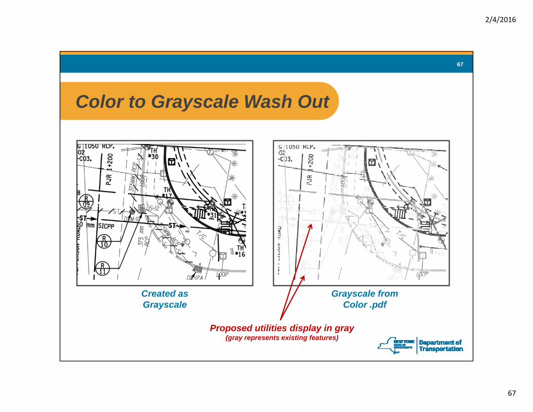
Color to Grayscale Wash OutColor to Grayscale Wash Out
Created as Grayscale
Grayscale from Color .pdf
Proposed utilities display in gray (gray represents existing features)
2/4/2016
68
68
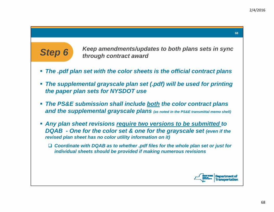
Step 6 Keep amendments/updates to both plans sets in sync Step 6 through contract award
The .pdf plan set with the color sheets is the official contract plans
The supplemental grayscale plan set (.pdf) will be used for printing the paper plan sets for NYSDOT use
The PS&E submission shall include both the color contract plans pand the supplemental grayscale plans (as noted in the PS&E transmittal memo shell)
Any plan sheet revisions require two versions to be submitted to DQAB - One for the color set & one for the grayscale set (even if theDQAB One for the color set & one for the grayscale set (even if the revised plan sheet has no color utility information on it)
Coordinate with DQAB as to whether .pdf files for the whole plan set or just for individual sheets should be provided if making numerous revisions
2/4/2016
69
69
Step 6 (continued)Step 6 (continued)
The suffix “_NoColor” differentiates between the filesSample file name for a revision to the color contract plan set: ‘D123456_R09_Plans_Vol1of6_Rev1.pdf’
The corresponding revision to the supplemental grayscale plan set would be: ‘D123456_R09_Plans_Vol1of6_NoColor_Rev1.pdf’
Amendments will identify the change to the color contract plan set along with mention of a revision to the supplemental information to bidders (i.e., the corresponding update to the supplemental grayscale plan set)
The color contract plan sheet revisions will be in the amendment document, while the revision to the supplemental information will be a separate file (same process as how supplemental info revisions are currently handled)
2/4/2016
70
70
Step 7 Make any field changes or as-built plans revisions to Step 7 the color plans
Refer to the MURK 1A (CAM) for guidance and procedures regarding field change sheets and as-built plans.
The contract plans are grayscale with color utilities. Therefore, any revisions to a plan sheet should be done to the color version of the plan sheet (i.e., don’t use grayscale only or B&W plan sheets as the base document for the revisions)document for the revisions).
Revisions preferably should be done electronically. If not, only revise a ‘first generation’ printed paper plan sheet (i.e., Don’t mark up photocopied plan sheets; colors degrade each time the sheets are photocopied).
Scan revisions to color .pdf files (or grayscale if no color utilities).A minimum resolution of 300 dpi is recommended. Balance file size with resolution. (Note: Original plan sets are printed at 600 dpi.)
Be aware that file size can be substantially larger (10x) for grayscale and color .pdf files than for B&W versions.
2/4/2016
71
71
New Setting Files & PrintingNew Setting Files & PrintingFor Current Design Files
Manually update the level assignments for each design file (key-in: “dgnlib update all”)
Stop using old .set files, color tables, and pen tablesStart using new setting files and tables
For New Design Files – No action required g q(just load the new resources & settings, no change to seed files)
Printer Queue Default SettingsPrinter defaults settings remain the ‘same’ (default remains black & white for most printers and color for plotters)
• Old Default: ‘B_size.pen’ & ‘bw.ctb’ (most common default setting for NYSDOT printers)
• New Default: ‘ny_b_basic.pen’ & ‘ny_bw.ctb’• Remember area shading displays solid when plotting in B&WRemember area shading displays solid when plotting in B&W• If desire color prints: Generate a color .pdf file, then use it as the source
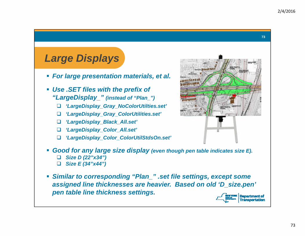
Good for any large size display (even though pen table indicates size E).Size D (22”x34”)Size E (34”x44”)
Similar to corresponding “Plan ” set file settings except someSimilar to corresponding Plan_ .set file settings, except some assigned line thicknesses are heavier. Based on old ‘D_size.pen’ pen table line thickness settings.
2/4/2016
74
74
Hatching vs Area ShadingHatching vs. Area Shading
Area Shading(minor contrast issue with cyan)
Hatching(can block other data & reduce legibility) (minor contrast issue with cyan)(can block other data & reduce legibility)
2/4/2016
75
75
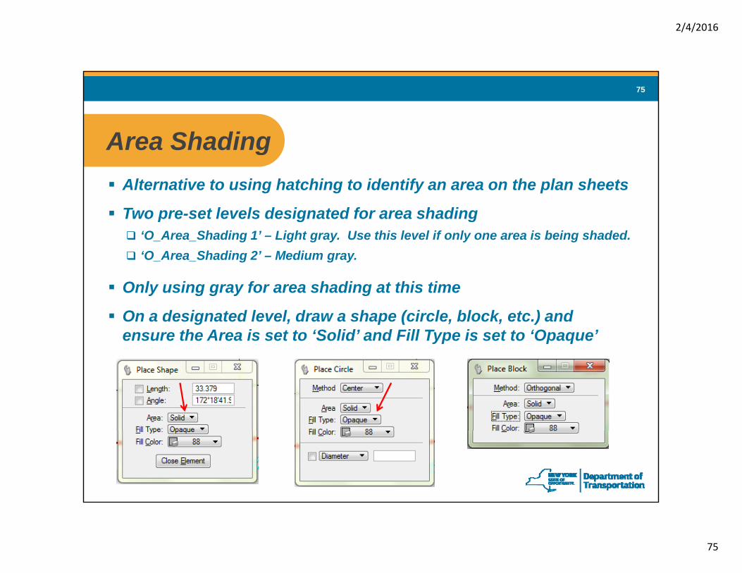
Area ShadingArea ShadingAlternative to using hatching to identify an area on the plan sheets
Two pre-set levels designated for area shadingTwo pre-set levels designated for area shading‘O_Area_Shading 1’ – Light gray. Use this level if only one area is being shaded.‘O_Area_Shading 2’ – Medium gray.
Only using gray for area shading at this timeOnly using gray for area shading at this time
On a designated level, draw a shape (circle, block, etc.) and ensure the Area is set to ‘Solid’ and Fill Type is set to ‘Opaque’
2/4/2016
76
76
Area Shading (continued)Area Shading (continued)
Recommend that each group of shapes are kept in separate files(i.e., shapes for general plans in one file, shapes for WZTC plans in another file)
Most of the new pen tables will print the shading behind the other data (may not display properly with the ‘ny b basic’ or ‘ny b bw’ pen table) ( y p y p p y y_ _ y_ _ p )
Be aware that shading may not look correct when printing in black & white and/or may display as a dark opaque area
If shapes for area shading are kept in separate reference files, users may needIf shapes for area shading are kept in separate reference files, users may need to set the ‘update sequence’ (a.k.a, display order, priorities, etc.) for the reference files so when viewing in CADD that the shading areas display in the background (otherwise they may mask/cover other data). Note: Regardless of whether any reference file update is established, information on levels ‘O_Area_Shading 1’ & ‘O_Area_Shading 2’ will plot/print properly in the background (this is controlled by the pen table).
2/4/2016
77
77
Line ThicknessLine Thickness
Minor adjustments made to some line thicknessesE l 1 Li W i ht 0 h d f 0 08 t 0 15 f i tiExample 1 – Line Weight 0 changed from 0.08mm to 0.15mm for existing
features (gray) and to 0.10mm for proposed features (black)
Example 2 – Line Weight 1 changed from 0.24mm to 0.25mm
No change to thickness for text (except for utilities)No change to thickness for text (except for utilities)
Color Utilities – Line & text thicknesses adjusted for each colorLines of same thickness but different colors tend to visually appear to be of diff t thi kdifferent thicknesses.
Assigned thicknesses were adjusted so each color element visually appears to be of similar thickness as other elements of similar weight.
Some colors required slightly heavier thickness assignments to ensure line integrity when the plan sheet is photocopied.
2/4/2016
78
78
Additional Color Plans GuidanceAdditional Color Plans Guidance
IntraDOT (Highway Design Manual > Chapter 21 > References)Copy of this presentation (to be posted)
• Good for overview & basic design library updating information
‘Design Guidance: Plans with Color Utilities, Gray Base Maps & Shading’• Provides more in-depth details & background information (except .dgnlib updating)
NYSDOT’s external website
Submit technical issues/problems through the Help DeskSubmit technical issues/problems through the Help Desk
Submit suggestions through your CADD Coordinator / EAMT Representative (Coordinators/Reps to then compile & submit to Rob Howland)