R322 - Revised 050411 REVO - R322 DRILL ORIGINAL INSTRUCTIONS WARNING ! When using electric power tools basic safety precautions should always be used to reduce the risk of fire, electric shock and personal injury. Read all of these instructions before attempting to operate this product and save these instructions Machine shown R322 - without the safety guard for clarity. G&J Hall Ltd, Burgess Road, Sheffield, S9 3WD, England Tel: +44 114 254 3206 Fax: +44 114 244 9256 Email: [email protected]Web: www.revo-tools.co.uk www.revo-tools.co.uk
Transcript
R322 - Revised 050411
REVO - R322 DRILL ORIGINAL INSTRUCTIONS
WARNING ! When using electric power tools basic safety precautions should always be used to reduce the risk of fire, electric shock and personal injury. Read all of these instructions before attempting to operate this product and save these instructions
Machine shown R322 - without the safety guard for clarity.
Machine Specification 3 Explanation of symbols used 4 Intended use of power tool 5 Prohibited use of power tool 5 Safety precautions 1 - Precautions and use of PPE. 6 2 - Special safety precautions - Magnetic Drills. 7 3 - Electrical safety 8 4 - Dust Extraction 8 5 - General safety instructions. 9-10 Installation instructions 1 - Unpacking and Assembly 11 2 - Setting-up or fixing tool in a stable position. 11 3 - Connection to power supply. 11 4 - Illustrated description of functions 12 5 - Limitations on ambient conditions 13 6 - Standard Accessories 13 7 - Disassembly and transportation 13 Operating instructions 1 - Setting and testing. 14 2 - Tool changing. Mounting of cutters into the arbor. 14 Removing the arbor and fitting the drill chuck 15 Using Twist Drills. 15 3 - Guards 16 4 - Clamping of work. (Magnet Control) 16 5 - Limits on size of work piece and type of material. Cutting Speeds/Materials—HSS cutters 17 Workpiece Material and size Limitations 17 6 - General instructions for use. Drill unit spindle control 18 Reversing of the handles 19 Normal operator position 19 Using the drill with annular cutters 20 7 - Lifting handles/transportation. 5 Maintenance and servicing 1 - Regular cleaning, maintenance and lubrication. 21 2 - Servicing by manufacturer. 22 3 - Special Tools 13 4 - Blockages of chips or work piece fragments. 20
3 R322 - Revised 050411
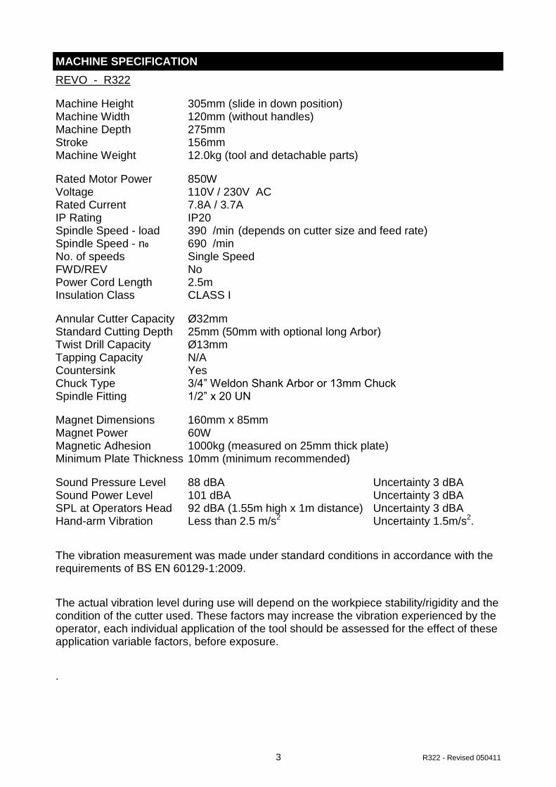
MACHINE SPECIFICATION
REVO - R322
Machine Height 305mm (slide in down position) Machine Width 120mm (without handles) Machine Depth 275mm Stroke 156mm Machine Weight 12.0kg (tool and detachable parts)
Rated Motor Power 850W Voltage 110V / 230V AC Rated Current 7.8A / 3.7A IP Rating IP20 Spindle Speed - load 390 /min
(depends on cutter size and feed rate)
Spindle Speed - n0 690 /min No. of speeds Single Speed FWD/REV No Power Cord Length 2.5m Insulation Class CLASS I
Annular Cutter Capacity Ø32mm Standard Cutting Depth 25mm (50mm with optional long Arbor) Twist Drill Capacity Ø13mm Tapping Capacity N/A Countersink Yes Chuck Type 3/4” Weldon Shank Arbor or 13mm Chuck Spindle Fitting 1/2” x 20 UN
Magnet Dimensions 160mm x 85mm Magnet Power 60W Magnetic Adhesion 1000kg (measured on 25mm thick plate) Minimum Plate Thickness 10mm (minimum recommended)
Sound Pressure Level 88 dBA Uncertainty 3 dBA Sound Power Level 101 dBA Uncertainty 3 dBA SPL at Operators Head 92 dBA (1.55m high x 1m distance) Uncertainty 3 dBA Hand-arm Vibration Less than 2.5 m/s
2 Uncertainty 1.5m/s
2.
The vibration measurement was made under standard conditions in accordance with the requirements of BS EN 60129-1:2009.
The actual vibration level during use will depend on the workpiece stability/rigidity and the condition of the cutter used. These factors may increase the vibration experienced by the operator, each individual application of the tool should be assessed for the effect of these application variable factors, before exposure.
.
4 R322 - Revised 050411
Symbol Meaning
Eye protection should be worn at all times when using this tool.
Hard Hat—Head protection should be worn at all times whilst using this tool, to protect from overhead hazards
Ear protection / Ear defenders should be worn at all times whilst using this tool, this tool exceed 85dB(A)
Electrical enclosure - risk of electric shock.
Read and understand the instruction manual - before operating this tool.
Caution ! / Attention !
Instruction Manual
WEEE - Waste of Electrical and Electronic Equipment This tool should be disposed of as Electrical & Electronic Waste.
EXPLANATION OF SYMBOLS USED
5 R322 - Revised 050411
INTENDED OF USE OF POWER TOOL
This power tool is intended to be used for drilling holes with annular cutters, twist drills, counterbores, countersinks and step drills in an industrial environment.
The machine is meant to be held onto a magnetisable surface using its electro-magnetic base.
The power tool should be used in a weather protected environment and be used with the accessories provided or Revo - Tools recommended accessories only.
The power tool can be used vertically, horizontally and upside down, provided the magnetic adhesion and work environment allow.
Cutting paste should be used rather than cutting fluid when using the machine in the upside down position to prevent ingress of fluids into the electrical system.
PROHIBITED USE OF POWER TOOL
This power tool should never be used without a ground or protective earth connection.
This power tool should not be used in a potentially explosive environment.
This power tool should not be use in a wet or humid environment where water could be drawn into the power tools cooling and ventilation system.
If the power tool is used in the upside down position, cutting fluids should not be used to prevent ingress of fluids into the electrical system, cutting paste should be used instead.
This power tool should never be positioned on a workpiece between the electrode and ground of an arc type welder. Damage to the machine will result as the welder will ground through the power tools ground or earth cable.
This power tool should not be used where the voltage is abnormally lower than the rated voltage, subject to voltage tolerances. Check the power tool rating plate, check the voltage available.
Operating on a lower than rated voltage will result in the electro magnet being at reduced power and the machine may become insecure whilst drilling.
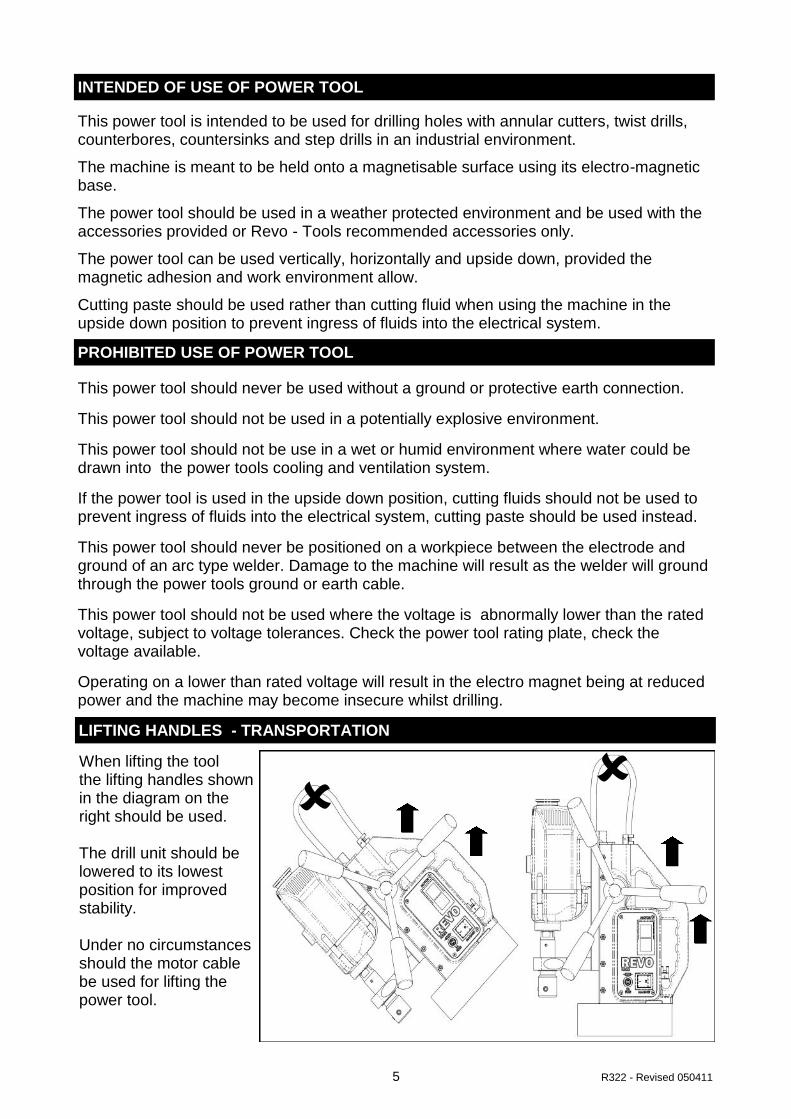
LIFTING HANDLES - TRANSPORTATION
When lifting the tool the lifting handles shown in the diagram on the right should be used. The drill unit should be lowered to its lowest position for improved stability. Under no circumstances should the motor cable be used for lifting the power tool.
6 R322 - Revised 050411
PERSONAL SAFETY AND USE OF PPE carry the power tool properly with the carrying
Attention Always watch what you are doing and use common sense at all times when operating power tools. Do not use the power tool whilst tired, or under the influence of drugs, alcohol or medication. A moment of inattention when using a power tool may result in personal injury. Clothing Always dress appropriately, do not wear loose clothing or jewellery. Contain long hair, keep your hair, clothing and gloves away from any moving parts. Loose clothes, jewellery or long hair can be caught in moving parts. Accidental Start-up Be sure all switches are in their OFF positions before plugging in the machine. When carrying or moving tools always keep your fingers away from the switches Plugging in a power tool with the switches in the ON position could invite accidents. Intentional Start-up Before starting up the power tool always remove any adjusting keys or tools. A wrench key left in a rotating part of the power tool may result in injury. Over Reaching Never over reach when using a power tool. Always ensure you have a proper stable footing and balance at all times before operating the tool. Proper footing and balance enables better control of the tool in case of unexpected situations. Personal Protective Equipment Always wear eye protection. Always wear ear protection. Always wear head protection. Always wear non-skid safety shoes. Where appropriate wear a dust mask and gloves depending on the working environment.
WORK IN A SAFE MANNER AT ALL TIMES
7 R322 - Revised 050411
SPECIAL SAFETY PRECAUTIONS - MAGNETIC DRILLS properly with the carrying
Safety Strap The electro-magnet base on this power tool can release if there is a interruption in power supply or electrical malfunction. The safety strap provided should be used at all times to prevent the power tool from falling in the event of power failure or electrical malfunction, possibly causing injury. The safety cam buckle strap should be attached to the fixing points provided and checked for security before commencing any drilling operation. Magnetic Adhesion The magnets strength depends on the thickness and condition of the work piece material. Always ensure that the work piece has a minimum thickness of 12mm or 1/2” to ensure there is adequate magnetic adhesion. If the work piece is less than 12mm or 1/2” then a piece of steel plate 12mm or 1/2” in thickness and larger than the magnet footprint must be inserted between the magnet and work piece to supplement the magnetic adhesion. The surface on which the magnet is placed should be clean, flat and clear from debris or rust. The base of the magnet should be inspected to ensure it is also clean flat and clear of debris. Always check the magnet is securely adhered to the work piece before commencing any drill operations. Do not use other appliances on the same power receptacle, any variation in voltage cause by other appliances could result in the magnet releasing. Always us the tool on its own power receptacle. This power tool can be used on a vertical surface or upside down provided there is sufficient magnetic adhesion, extra care should be taken when drilling vertically or upside down . When using the machine vertically or upside down it is possible hot and sharp swarf or chips may fall. Always wear appropriate personal protective equipment When Cutting When using coolant of lubricants, ensure coolants and lubricants do not enter the drill units ventilation/cooling openings. If the drill is used in the upside down position, use cutting paste instead of cutting fluid to prevent the possibility of fluids entering the electrical system. When using annular cutters ensure that the slug ejected at the end of the cut will not endanger anyone in the vicinity, if working at height some form of collection device for the ejected slug may be necessary. Care should be taken with the ejected slug, this will be both hot and sharp, gloves should be worn when handling the slug.
8 R322 - Revised 050411
.
ELECTRICAL SAFETYAlways carry the power tool properly with the carrying handles
Earthing / Grounding. This power tool requires a ground or earth connection.
The power tool must be plugged into an outlet properly installed and grounded or earthed
in accordance with all local codes and regulations.
Never remove or tamper with the ground or earth prong in any way.
Do not use adaptor plugs.
If the tool should electrically malfunction or breakdown, grounding or earthing will provide a low resistance patch to carry harmful electricity away from the user. Power Cord Never carry the power tool by its power cord or electrical hose.
Keep power cords away from heat, oil and sharp edges.
Never pull the power cord to disconnect it from the receptacle.
Always carry the power tool properly with the carrying handles provided.
Periodically inspect the power cord for damage,
If any damage is found the power tool should not be used until the damage has been repaired by a qualified electrician.
A damaged power cord will increase the risk of electric shock. Using the Power Tool Outside Do not expose the power tool to rain or wet conditions, water entering the power tool will increase the risk of electric shock.
When operating the power tools outside, if required, an extension cord rated for outdoor use should be used.
These extension cords are rated for outdoor use and reduce the risk of electric shock. Electrical Enclosure The electrical components on this power tool are housed within the main body casting, this and the side panels of the main body create an electrical enclosure.
The panels should not be removed except by a suitable trained or qualified electrician.
DUST EXTRACTION
This tool is intended for drill holes in ferrous metals, if using on materials such as cast iron where dust might be created, suitable dust extraction should be used. This is both to protect the operator and to protect the motor inlet from ingress of harmful dust particles. Operators should wear suitable dust masks if dust is created whilst working.
9 R322 - Revised 050411
1 - Keep work area clear Cluttered areas and benches invite injuries. 2 - Consider work area environment Do not expose tools to rain. Do not use tools in damp or wet locations. Keep work area well lit. Do not use tools in the presence of flammable liquids or gases. 3 - Guard against electric shock Avoid body contact with earthed or grounded surfaces (e.g. pipes, radiators, ranges, refrigerators). 4 - Keep other persons away Do not let persons, especially children, not involved in the work touch the tool or the extension cord and keep them away from the work area. 5 - Store idle tools When not in use, tools should be stored in a dry locked-up place, out of reach of children. 6 - Do not force the tool It will do the job better and safer at the rate for which it was intended. 7 - Use the right tool Do not force small tools to do the job of a heavy duty tool. Do not use tools for purposes not intended; for example do not use circular saws to cut tree limbs or logs. 8 - Dress properly Do not wear loose clothing or jewellery, they can be caught in moving parts. Non-skid footwear is recommended when working outdoors. Wear protective hair covering to contain long hair. 9 - Use protective equipment Use safety glasses. Use face or dust mask if working operations create dust. 10 - Connect dust extraction equipment If the tool is provided for the connection of dust extraction and collecting equipment, ensure these are connected and properly used. 11 - Do not abuse the cord Never yank the cord to disconnect it from the socket. Keep the cord away from heat, oil and sharp edges. . 12 - Secure work Where possible use clamps or a vice to hold the work. It is safer than using your hand. 13 - Do not overreach Keep proper footing and balance at all times.
GENERAL SAFETY
10 R322 - Revised 050411
14 - Maintain tools with care Keep cutting tools sharp and clean for better and safer performance. Follow instruction for lubricating and changing accessories. Inspect tool cords periodically and if damaged have them repaired by an authorized service facility. Inspect extension cords periodically and replace if damaged. Keep handles dry, clean and free from oil and grease . 15 - Disconnect tools When not in use, before servicing and when changing accessories such as blades, bits and cutters, disconnect tools from the power supply. 16 - Remove adjusting keys and wrenches Form the habit of checking to see that keys and adjusting wrenches are removed from the tool before turning it on. 17 - Avoid unintentional starting Ensure switch is in "off" position when plugging in. 18 - Use outdoor extension leads When the tool is used outdoors, use only extension cords intended for outdoor use and so marked. 19 - Stay alert Watch what you are doing, use common sense and do not operate the tool when you are tired. 20 - Check damaged parts Before further use of tool, it should be carefully checked to determine that it will operate properly and perform its intended function. Check for alignment of moving parts, binding of moving parts, breakage of parts, mounting and any other conditions that may affect its operation. A guard or other part that is damaged should be properly repaired or replaced by an authorized service centre unless otherwise indicated in this instruction manual. Have defective switches replaced by an authorized service centre. Do not use the tool if the switch does not turn it on and off. 21 - Warning The use of any accessory or attachment other than one recommended in this instruction manual may present a risk of personal injury. 22 - Have your tool repaired by a qualified person This electric tool complies with the relevant safety rules. Repairs should only be carried out by qualified persons using original spare parts, otherwise this may result in considerable danger to the user.
GENERAL SAFETY - CONT.
11 R322 - Revised 050411
UNPACKING AND ASSEMBLY
The REVO R322 comes in a rugged blow moulded carrying case before first use:- 1. Remove the machine from the carrying case. (Note:- 12.0kg weight) 2. Fit the three screw in handles to the pinion shaft. 3. Fit the safety guard as shown in the instructions, see “Using the safety guard” 4. Fit the arbor, as detailed in the instructions under “Fitting the Drill Chuck / Arbor”
SETTING UP THE TOOL
Before using the tool please ensure you have read the sections on the intended and prohibited of use of the machine. The machine should only be used for hole drilling whilst attached to the work piece by the electro-magnetic base. This machine is intended for use at any angle, but only if the electro-magnet is in full working order and has sufficient hold on the work piece material. The safety strap should be attached in case of power failure or machine malfunction. The safety strap should NOT be used as an alternative to the magnet for clamping purposes. Always ensure the strap is correctly fitted and the machine is secure BEFORE starting
CONNECTION TO THE POWER SUPPLY
Connection to the power supply is by 2.5m cable and plug. For the 230V machine this is by a 3 pin plug with earth connection. For the 110V machine this is via a CEE type 2pin+earth plug. The BS1363 plug version is fused, the European Schuko type plug is not fused. This tool is CLASS I insulation and MUST be earthed, any power socket the tool is connected to must have an earth. Before the power cord is connected the magnet switch should be in the OFF position. The power cord assembly is a custom terminated one, replacement should only be car-ried out by a qualified electrician. Only use the replacement parts listed below. Power cord part numbers:- 230V ~ BS Plug 18X503 230V ~ EU Plug 18X503/EU (Shuko / VDE) 110V ~ 2P+E 18Y181 For connection information, should the power cord need to be replaced, please refer to the wiring diagram in this manual or the connection label inside the rear panel of the power tool.
12 R322 - Revised 050411
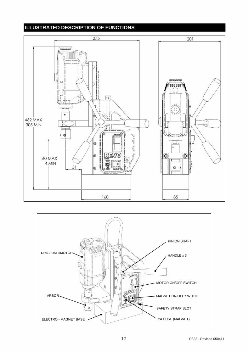
ILLUSTRATED DESCRIPTION OF FUNCTIONS
ELECTRO - MAGNET BASE 2A FUSE (MAGNET)
MAGNET ON/OFF SWITCH
MOTOR ON/OFF SWITCH
PINION SHAFT
HANDLE x 3
ARBOR
DRILL UNIT/MOTOR
SAFETY STRAP SLOT
13 R322 - Revised 050411
LIMITATIONS ON AMBIENT CONDITIONS
This power tool is has an ingress protection rating of IP20, it should not be used in dusty or damp environments. The power tool should be used in a weather protected environment. Precautions should be taken to ensure dust does not enter the ventilation system of the power tool causing clogging and overheating. Power tools produce sparks that may ignite flammable substances such as gases, flammable liquids or dust. Do not operate this power tool in a potentially explosive environment.
Ambient temperatures of >45°C should be avoided.
DISASSEMBLY & TRANSPORTATION
When the machine is not in use it should be stored in the carrying case provided. Any cutters should be removed after use. The drill unit should be wound down into a low position. The three pinion handles need to be removed before placing the tool in the case. Any additional tools or accessories should be stored in the case. Make sure the case is securely closed and latches are secure before lifting the carrying case.
The REVO R322 is supplied in a rugged carrying case with the following as standard :-
3/4” Weldon Shank Arbor (25mm cut depth) Safety Cam Buckle Strap Safety Guard 250ml Bottle of Cutting Oil Allen Key Set 13mm Drill Chuck and Key
STANDARD ACCESSORIES
SPECIAL TOOLS
All tools required for the safe operation and maintenance of this power tools are provided within the standard accessories, no additional tools should be required.
14 R322 - Revised 050411
SETTING AND TESTING - USING THE SAFETY STRAP
The holder for the cutting tool is known as the arbor. The arbor is designed to accept Powerbor 3/4” Weldon shank annular cutters. The Powerbor annular cutters normally have two flats disposed at 90°to each other. To mount the cutter. First ensure the ejector pin is in place. Align the flats with the two fixing screws. Push the cutter up into the arbor until it stops. Tighten the two fixing screws onto the cutter flats with the hex keys supplied.
MOUNTING CUTTERS INTO THE ARBOR
CAM BUCKLE
STRAP SLOT
PRESS HERE FEED
THROUGH THIS WAY
A cam buckle type safety strap is provided. The power tool has a strap slot to allow the safety strap to be attached securely. Always ensure the strap is correctly fitted and the machine is secure BEFORE starting the motor unit. The safety strap is used to reduce the risk of injury in the case of a power supply or electrical malfunction. A correctly fitted safety strap will hold the power tool if the electro-magnet looses its magnetic adhesion. If the strap becomes damaged or lost, it must be replaced BEFORE using the power tool. DO NOT use the safety strap as an alternative clamping method, the electro-magnet should have good magnetic adhesion at all times whilst using this power tool.
15 R322 - Revised 050411
FITTING THE DRILL CHUCK SUPPLIED
To replace the arbor (A) with the drill chuck supplied first remove the arbor. To do this, using the spanners supplied, place one spanner on the flats of the drill output shaft. Turn clockwise (as viewed from above) until the spanner meets the dovetail slide. Place the the second spanner on the flats of the arbor, apply pressure, again clockwise as viewed from above. If possible the magnet can be used to hold the machine whilst removing the arbor. If the arbor is tight the spanner on the arbor flats can be tapped with a soft mallet. Once the arbor is unscrewed the arbor support bracket (B) needs to be removed. This is accomplished by removing the two hexagon socket head cap screws. To fit the drill chuck simply screw it into place on the spindle nose. A special left handed screw is provided to hold the chuck. Replacement of the arbor is a reversal of the procedure above.
TO REMOVE ARBOR A
B
USING TWIST DRILLS
Twist drills can be used with the R322. To accommodate twist drills, or any plain shank cutting tool, the R322 is supplied as standard with a 13mm drill chuck and key. The drill chuck takes standard parallel shank twist drills of up to 1.5 - 13mm.
16 R322 - Revised 050411
SAFETY GUARD carry the power
CLAMPING - MAGNET CONTROL
An electro-magnet is used for clamping the tool onto the workpiece. The magnet is controlled by the magnet switch (F) located at the bottom of the control panel. „O‟ indicates magnet OFF „I‟ indicates magnet ON. Ensure the magnet switch is OFF before connecting the power supply. Ensure the magnet is clean and free from debris and that the machine is on a flat clean ferrous surface of the required minimum thickness (10mm). To switch the magnet ON, press the switch to the „I‟ position, the switch will illuminate to indicate there is a power supply to the machine. The security of the magnet should always be physically checked BEFORE starting the drill unit. The magnet is protected by a 20mm 2A fast acting fuse (G).
FIXING SCREW
SAFETY GUARD
A safety guard is supplied with this power tool, it should be attached BEFORE using the power tool. The guard is attached at 1 point, by a button head screw to the motor. The nylon washer should be closest to the guard with the spring washer between the nylon washer and the screw head. The screw should be tightened just enough to allow the spring washers to hold the guard up. The guard has approximately 50mm of travel which is adequate standard length cutters. The guard should be adjusted so it is able to slide with light pressure.
F
G
MOTOR
17 R322 - Revised 050411
The REVO R322 is a single speed drill unit with a nominal load speed of 390 rev/min. Under load the R322 will regulate its speed depending on the load applied. ie: a small cutter will run faster than a larger cutter (if the same feed rate is applied) The R322 has the optimum power / torque / spindle speed for HSS annular and TCT
cutters in the range Ø12mm to Ø 32mm, cutting EN10025 S235J steel or its equivalent. The R322 can also be used on other materials such as high tensile steel and stainless steel if the appropriate speed for the material to be cut is selected.
CUTTING SPEEDS/MATERIALS—HSS CUTTERS
Cutting Speeds—suggested speed rates for varying cutter diameters / materials
The electro - magnet clamping force is measured as the pull off load when clamped on a steel plate (EN10025 S235J or its equivalent) of 25mm thickness, flat with a good surface and free from rust and debris. For any other workpiece material the clamping force will be different, any difference in workpiece thickness and the clamping force will deviate. The minimum recommended plate thickness for the electro-magnet is 12mm thick. If the workpiece is thinner than recommended then an additional plate, made of suitable material should be added by clamping to the workpiece, this will help the electro-magnet become more secure. BEFORE using the drill always ensure the magnet is held onto the work piece securely.
18 R322 - Revised 050411
OPERATION - SPINDLE - START / STOP
The drill unit or “motor” is controlled by a twin push button switch (H) at the top of the control panel. The green button is ON the red button is OFF. The green button is below with the surrounding bezel. The red button is raised above the surrounding bezel. This is to prevent inadvertent operation of the drill unit. The motor will not operate unless the magnet is switched ON first. BEFORE starting the motor, the security of the magnet should be physically checked, if any movement is possible this should be rectified BEFORE using the drill. The motor control has an under-voltage relay, if the power is interrupted the motor will stop and will not restart when the power is resumed until the motor control is operated again.
H
MOTOR
19 R322 - Revised 050411
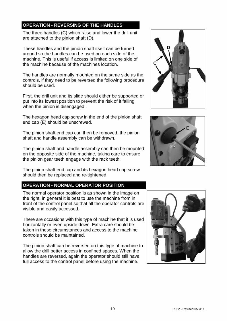
OPERATION - REVERSING OF THE HANDLES
The three handles (C) which raise and lower the drill unit are attached to the pinion shaft (D). These handles and the pinion shaft itself can be turned around so the handles can be used on each side of the machine. This is useful if access is limited on one side of the machine because of the machines location. The handles are normally mounted on the same side as the controls, if they need to be reversed the following procedure should be used. First, the drill unit and its slide should either be supported or put into its lowest position to prevent the risk of it falling when the pinion is disengaged. The hexagon head cap screw in the end of the pinion shaft end cap (E) should be unscrewed. The pinion shaft end cap can then be removed, the pinion shaft and handle assembly can be withdrawn. The pinion shaft and handle assembly can then be mounted on the opposite side of the machine, taking care to ensure the pinion gear teeth engage with the rack teeth. The pinion shaft end cap and its hexagon head cap screw should then be replaced and re-tightened.
E
OPERATION - NORMAL OPERATOR POSITION
The normal operator position is as shown in the image on the right, in general it is best to use the machine from in front of the control panel so that all the operator controls are visible and easily accessed. There are occasions with this type of machine that it is used horizontally or even upside down. Extra care should be taken in these circumstances and access to the machine controls should be maintained. The pinion shaft can be reversed on this type of machine to allow the drill better access in confined spaces. When the handles are reversed, again the operator should still have full access to the control panel before using the machine.
C
D
20 R322 - Revised 050411
OPERATION - USING THE DRILL WITH ANNULAR CUTTERS
Insert the correct pilot pin into the pilot pin hole through the shank of the cutter. Mount the cutter in the tool holder (arbor) of the machine as described in previous chapters, ensuring the cutter is secure and correctly fitted. Position the machine on the work piece ensuring the magnet is on a flat clean ferrous surface and the work piece is not below the minimum recommended thickness. Use the pilot pin to align the centre of the cutter to the desired hole position. Switch on the magnet and physically check the machine is securely adhered to the work piece. Once in position, attach the safety strap, if the magnetic adhesion fails for some reason the safety strap will reduce movement of the machine. Apply cutting fluid through the small holes in the arbor, the arbor has a small reservoir for coolant which is fed down through the central pin hole to the cutter. The use of cutting fluid will enhance the quality of the cut and prolong the life of the cutter. Lower the safety guard provided. Switch on the drill motor, feed the cutter down by using the three handles provided. Proceed with caution, apply pressure gradually until the cutter has formed a groove of approx 3mm (1/8”). Once a groove is established the pressure can be increased. DO NOT apply excessive pressure, if excessive pressure is required it is a sign the cutter may be worn, continuing to use a worn cutter will result in damage to the drill motor. If the drill motor slows significantly under load ease off the downward pressure. On deep holes it may be necessary to withdraw the cutter to remove swarf and to apply more cutting fluid. A cutter in good condition will need only moderate feed pressure and will produce continuous chips or swarf. Broken chips or swarf indicate a cutter or material problem, so care should be taken.
OPERATION - BLOCKAGES OF CHIPS AND WORKPIECE FRAGMENTS
If excessive swarf builds up during the cut it may be necessary to withdraw the cutter to remove the swarf, care should be taken as the swarf will be both hot and sharp. As the cutter begins to break through, the feed pressure should be reduced slightly. When the cutter breaks through, a slug of material at the centre of the cut will be ejected. This will be both hot and sharp. Care should be taken when handling the slug. Care should be taken that the ejection slug is safe and can not injure anyone in the vicinity, the slug should be prevented from falling where possible.
21 R322 - Revised 050411
MAINTENANCE - GENERAL
To keep this machine in a safe working condition regular certain maintenance is required. 1. The gib strip on the dovetail slide must be adjusted to eliminate any free play. 2. The dovetail slides will need to be lubricated will oil periodically. 3. The magnetic base should be inspected for damage on its magnetic surface or for
any damage to the resin, any damage should be repaired before using the drill. 4. A monthly inspection of the carbon brushes is recommended, excessive wear could
lead to motor damage or malfunction.
MAINTENANCE - REPLACING BRUSHES
ACCESSORIES
18Y170 CHUCK ADAPTOR
This allows a drill chuck to be quickly placed into the arbor of the machine.
18YPIPE PIPE CLAMP
This allows the drill to be mounted on a pipe or cylindrical object, the magnet attaches to the “saddle” so the material of the workpiece does not need to be magnetic.
The carbon brushes (M) can be removed by simply unscrewing the brush cap (L). The brush has a spring and metal cap attached, simply withdraw the brush to inspect or replace it. When replacing the brush, slide it into the brush holder, make sure the metal cap of the brush seats in the recess on the brush cap, then screw the brush cap home. Always use genuine replacement parts. The brushes on this drill unit have an auto stop feature, when the brush reaches its wear limit to motor will stop until the brushes are replaced
L
M
22 R322 - Revised 050411
MAINTENANCE - TOOL USE AND CARE carry the power tool properly with the carrying
Always ensure the work piece is secure and stable before attempting to work on it. Do not force the tool, always use the correct type of cutting tool for your application and use it at the rate it was designed to work at. Do not use the power tool if the power switch does not turn it on or off, any tool which can not be turned on or off with the switch is dangerous and must be repaired before use. Always disconnect the plug from the power supply before making any adjustments, changing accessories or storing the tool. This will prevent the risk of the starting the tool accidentally. Always store tools not in use out of reach of children and untrained persons. Tools are dangerous in the hands of an untrained user. Maintain all cutting tools with care, keep them sharp and clean, properly maintained tools with sharp edges are less likely to bind and will be easier to control. Do not operate the power tool with dull or damaged cutting tools, this may overload the motor. Check the power tools periodically for misalignment or binding of moving parts, also broken parts or any other condition that may affect the tools operation. If damaged have the tool serviced before using, Poorly maintained tools can cause accidents. Use only Revo - Tools recommended accessories, accessories made for other power tools may not be suitable and could become hazardous when used.
SERVICE the power tool properly with the carrying handles provided.
Only trained repair personnel should perform tool service. Service or maintenance performed by untrained personnel could result in a risk of injury. When servicing the power tool, only use identical replacement parts, pay attention to the power tools voltage rating and model number to ensure the correct replacement parts are specified.
R E V O - T O O L S W A R R A N T Y S T A T E M E N T Revo -Tools warrants its magnetic drills for one (1) year from the date of purchase
against defects due to faulty material or workmanship and will repair or replace (at its op-tion) without charge, any items returned. This warranty is void if the item has been dam-
aged by accident or unreasonable use, neglect, improper service or other causes not arising out of defects in material workmanship. No other expressed warranty is given or authorised. Revo - Tools disclaims any implied warranty of merchantability or fitness for
any period beyond the expressed warranty, and shall not be liable for incidental or consequential damages. To obtain warranty service, return the item(s) to your nearest
factory authorised repair centre. This warranty is on lieu of any other warranty, expressed or implied, including any
warranty of merchantability or fitness for a particular purpose.
WARRANTY
23 R322 - Revised 050411
R322 WIRING DIAGRAMS
24 R322 - Revised 050411
REVO R322 STAND PARTS
ITEM Part No. Description
1 18Y138/G MAIN BODY CASTING (GREY)
2 18Y134 ELECTRO-MAGNET BASE
3 18X312 BRASS GUIDES (PAIR)
4 18Y140 MACHINE RACK - INC. SCREWS
5 18X411 DOVETAIL SLIDE
6 18Y201 ARBOR SUPPORT BRACKET - INC BUSH
7 18Y130 ARBOR ASSEMBLY (1/2" X 20 UN)
8 18X321 ARBOR SPRING
9 18X323 ARBOR PISTON
10 18X206 INTERNAL CIRCLIP
11 18X417 SPINDLE BUSH ONLY
12 18X310 REVO SAFETY GUARD
13 18X311 RETAINING BRACKET
14 18X524 PINION END CAP
15 18X502 PINION BUSH
16 18Y144 PINION SHAFT - INC CAP & SCREW
17 18X718 HANDLE (12mm)
18 18X520 KNOB (12mm)
17+18 18Y145 HANDLE/KNOB COMPLETE
19 18X519 CABLE GLAND (CORD GRIP)
20 18X503/2 REVO CABLE FLEX TO MOTOR
21 18Y181 MAINS CABLE 110V (2P+E)
22 18X503 MAINS CABLE 230V (UK)
ITEM Part No. Description
23 18X454 R322 REAR PANEL
24 18X515 RECTIFIER UNIT
25 18X455 R322 CONTROL PANEL
26 18X406 MOTOR START/STOP SWITCH - 110V
27 18X407 MOTOR START/STOP SWITCH - 230V
28 18X456 MAGNET SWITCH - 0 & I MARKINGS
29 18X457 R322 FUSE HOLDER
30 18X512 2A FUSE
31 18X224 M5 x 18 CONE POINT SCREW
32 18X219 M5 NUT
33 18X205 M8 X 8 SKT SCREW
34 18X430 POWER CABLE STRAIN RELIEF BUSH
NOT SHOWN
35 18X470 PLASTIC CASE
36 18ZA02B 13mm DRILL CHUCK & KEY
36 18Y170 CHUCK ADAPTOR - ACCESORY
37 18X419 SAFETY STRAP - CAM BUCKLE
25 R322 - Revised 050411
REVO R322 DRILL PARTS
ITEM Part No. Description
38 18X451 COMPLETE DRILL UNIT - 110V
39 18X452 COMPLETE DRILL UNIT - 230V
40 18X432 SET OF CARBON BRUSHES
41 18X433 BRUSH CAP
42 18X5620 5.5 x 25 SCREW
NOTE: The replaceable parts for the drill unit are limited to carbon brushes, brush caps and fixing screws only. If the drill unit becomes unserviceable due to wear, it is normally more cost effective to replace the entire drill unit.
26 R322 - Revised 050411
27 R322 - Revised 050411
28 R322 - Revised 050411
WARRANTY REGISTRATION Thank you for purchasing your REVO-Tools magnetic based drilling machine. To ensure any warranty claim can be processed promptly, please register your machine, now, on-line at :-
http://www.revo-tools.co.uk
Click on the button on the left “REVO WARRANTY REGISTRATION”