154
5000 Series Troubleshooting Guide P/N 83-00004296-10 Revision A October 2007

5000 Series Troubleshooting Guide
P/N 83-00004296-10Revision A
October 2007

Copyright Protected Material 2002-2007. All rights reserved. R/Evolution and the R/Evolution logo are trademarks of Dot Hill Systems Corp. All other trademarks and registered trademarks are proprietary to their respective owners.The material in this document is for information only and is subject to change without notice. While reasonable efforts have been made in the preparation of this document to assure its accuracy, changes in the product design can be made without reservation and without notification to its users.

3
Contents
Preface . . . . . . . . . . . . . . . . . . . . . . . . . . . . . . . . . . . . . . . . . . . . . . . . . . . . . . . . . . . . 9
1. System Architecture . . . . . . . . . . . . . . . . . . . . . . . . . . . . . . . . . . . . . . . . . . . . . . . . 11
Architecture Overview . . . . . . . . . . . . . . . . . . . . . . . . . . . . . . . . . . . . . . . . . . . . . . . 11
Enclosure Chassis and Midplane . . . . . . . . . . . . . . . . . . . . . . . . . . . . . . . . . . . . . . . 12
Midplane . . . . . . . . . . . . . . . . . . . . . . . . . . . . . . . . . . . . . . . . . . . . . . . . . . . . . . 12
Enclosure ID Display . . . . . . . . . . . . . . . . . . . . . . . . . . . . . . . . . . . . . . . . . . . . 13
Drive Modules . . . . . . . . . . . . . . . . . . . . . . . . . . . . . . . . . . . . . . . . . . . . . . . . . . . . . 14
Disk Drives . . . . . . . . . . . . . . . . . . . . . . . . . . . . . . . . . . . . . . . . . . . . . . . . . . . . 15
Drive Module Dongle . . . . . . . . . . . . . . . . . . . . . . . . . . . . . . . . . . . . . . . . . . . . 15
FC Controller Module . . . . . . . . . . . . . . . . . . . . . . . . . . . . . . . . . . . . . . . . . . . . . . . 16
Power-and-Cooling Modules . . . . . . . . . . . . . . . . . . . . . . . . . . . . . . . . . . . . . . . . . . 20
Power Supply Unit . . . . . . . . . . . . . . . . . . . . . . . . . . . . . . . . . . . . . . . . . . . . . . 20
Cooling Fans . . . . . . . . . . . . . . . . . . . . . . . . . . . . . . . . . . . . . . . . . . . . . . . . . . . 20
Airflow . . . . . . . . . . . . . . . . . . . . . . . . . . . . . . . . . . . . . . . . . . . . . . . . . . . . . . . 22
2. Fault Isolation Methodology . . . . . . . . . . . . . . . . . . . . . . . . . . . . . . . . . . . . . . . . . 23
Gather Fault Information . . . . . . . . . . . . . . . . . . . . . . . . . . . . . . . . . . . . . . . . . . 23
Determine Where the Fault Is Occurring . . . . . . . . . . . . . . . . . . . . . . . . . . . . . . 23
Review the Event Logs . . . . . . . . . . . . . . . . . . . . . . . . . . . . . . . . . . . . . . . . . . . 24
Isolate the Fault . . . . . . . . . . . . . . . . . . . . . . . . . . . . . . . . . . . . . . . . . . . . . . . . . 24

4 R/Evolution 5000 Series Troubleshooting Guide • October 2007
3. Troubleshooting Using System LEDs . . . . . . . . . . . . . . . . . . . . . . . . . . . . . . . . . . 25
LED Names and Locations . . . . . . . . . . . . . . . . . . . . . . . . . . . . . . . . . . . . . . . . . . . 25
Using LEDs to Check System Status . . . . . . . . . . . . . . . . . . . . . . . . . . . . . . . . . . . . 27
Using Enclosure Status LEDs . . . . . . . . . . . . . . . . . . . . . . . . . . . . . . . . . . . . . . 28
Using Drive Module LEDs . . . . . . . . . . . . . . . . . . . . . . . . . . . . . . . . . . . . . . . . 28
Using Controller Module Host Port LEDs . . . . . . . . . . . . . . . . . . . . . . . . . . . . 29
Using the Controller Module Expansion Port LED . . . . . . . . . . . . . . . . . . . . . . 30
Using Ethernet Management Port LEDs . . . . . . . . . . . . . . . . . . . . . . . . . . . . . . 32
Using Controller Module Status LEDs . . . . . . . . . . . . . . . . . . . . . . . . . . . . . . . 32
Using Power-and-Cooling Module LEDs . . . . . . . . . . . . . . . . . . . . . . . . . . . . . 33
Using Expansion Module LEDs . . . . . . . . . . . . . . . . . . . . . . . . . . . . . . . . . . . . 33
4. Troubleshooting Using RAIDar . . . . . . . . . . . . . . . . . . . . . . . . . . . . . . . . . . . . . . 35
Determining Storage System Status and Verifying Faults . . . . . . . . . . . . . . . . . . . . 36
Stopping I/O . . . . . . . . . . . . . . . . . . . . . . . . . . . . . . . . . . . . . . . . . . . . . . . . . . . . . . . 37
Isolating Faulty Disk Drives . . . . . . . . . . . . . . . . . . . . . . . . . . . . . . . . . . . . . . . . . . 39
Identifying a Faulty Disk Drive . . . . . . . . . . . . . . . . . . . . . . . . . . . . . . . . . . . . 39
Reviewing Disk Drive Error Statistics . . . . . . . . . . . . . . . . . . . . . . . . . . . . . . . 40
Reviewing the Event Logs . . . . . . . . . . . . . . . . . . . . . . . . . . . . . . . . . . . . . . . . 42
Reconstructing a Virtual Disk . . . . . . . . . . . . . . . . . . . . . . . . . . . . . . . . . . . . . . 43
Isolating Data Path Faults . . . . . . . . . . . . . . . . . . . . . . . . . . . . . . . . . . . . . . . . . . . . 44
Isolating Internal Data Path Faults . . . . . . . . . . . . . . . . . . . . . . . . . . . . . . . . . . 44
Isolating External Data Path Faults on an FC Storage System . . . . . . . . . . . . . 49
Resetting a Host Channel on an FC Storage System . . . . . . . . . . . . . . . . . . . . . 50
Isolating Disk Drive Faults . . . . . . . . . . . . . . . . . . . . . . . . . . . . . . . . . . . . . . . . . . . 50
Clearing Metadata From Leftover Disk Drives . . . . . . . . . . . . . . . . . . . . . . . . . . . . 51
Using Diagnostic Functions . . . . . . . . . . . . . . . . . . . . . . . . . . . . . . . . . . . . . . . . . . . 52
Trusting a Virtual Disk for Disaster Recovery . . . . . . . . . . . . . . . . . . . . . . . . . 52
Clearing Unwritable Cache Data . . . . . . . . . . . . . . . . . . . . . . . . . . . . . . . . . . . . 54

Contents 5
Viewing the Debug Log . . . . . . . . . . . . . . . . . . . . . . . . . . . . . . . . . . . . . . . . . . . 54
Viewing Crash and Boot Data . . . . . . . . . . . . . . . . . . . . . . . . . . . . . . . . . . . . . . 55
Viewing a CAPI Command Trace . . . . . . . . . . . . . . . . . . . . . . . . . . . . . . . . . . . 56
Viewing a Management Trace . . . . . . . . . . . . . . . . . . . . . . . . . . . . . . . . . . . . . . 57
Selecting Individual Events for Notification . . . . . . . . . . . . . . . . . . . . . . . . . . . 58
Selecting or Clearing All Events for Notification . . . . . . . . . . . . . . . . . . . . . . . 59
Enabling Service Interfaces . . . . . . . . . . . . . . . . . . . . . . . . . . . . . . . . . . . . . . . . 60
Restoring Management Controller Defaults Only . . . . . . . . . . . . . . . . . . . . . . . 61
Changing Fault Isolation and PHY Settings . . . . . . . . . . . . . . . . . . . . . . . . . . . 62
Using Recovery and Debug Utilities . . . . . . . . . . . . . . . . . . . . . . . . . . . . . . . . . . . . 63
Dequarantining a Virtual Disk . . . . . . . . . . . . . . . . . . . . . . . . . . . . . . . . . . . . . . 63
Saving Log Information to a File . . . . . . . . . . . . . . . . . . . . . . . . . . . . . . . . . . . . 64
Problems Using RAIDar to Access a Storage System . . . . . . . . . . . . . . . . . . . . . . . 66
Problems Scheduling Tasks . . . . . . . . . . . . . . . . . . . . . . . . . . . . . . . . . . . . . . . . . . . 67
Create the Task . . . . . . . . . . . . . . . . . . . . . . . . . . . . . . . . . . . . . . . . . . . . . . . . . 67
Schedule the Task . . . . . . . . . . . . . . . . . . . . . . . . . . . . . . . . . . . . . . . . . . . . . . . 67
Resetting the Clock . . . . . . . . . . . . . . . . . . . . . . . . . . . . . . . . . . . . . . . . . . . . . . 68
Deleting Tasks . . . . . . . . . . . . . . . . . . . . . . . . . . . . . . . . . . . . . . . . . . . . . . . . . . 68
Errors Associated with Scheduling Tasks . . . . . . . . . . . . . . . . . . . . . . . . . . . . . 69
5. Troubleshooting Using Event Logs . . . . . . . . . . . . . . . . . . . . . . . . . . . . . . . . . . . . 71
Event Severities . . . . . . . . . . . . . . . . . . . . . . . . . . . . . . . . . . . . . . . . . . . . . . . . . . . . 71
Viewing the Event Log in RAIDar . . . . . . . . . . . . . . . . . . . . . . . . . . . . . . . . . . . . . . 72
Viewing an Event Log Saved From RAIDar . . . . . . . . . . . . . . . . . . . . . . . . . . . . . . 73
Reviewing Event Logs . . . . . . . . . . . . . . . . . . . . . . . . . . . . . . . . . . . . . . . . . . . . . . . 74
Configuring the Debug Log . . . . . . . . . . . . . . . . . . . . . . . . . . . . . . . . . . . . . . . . . . . 75
Viewing the Debug Log . . . . . . . . . . . . . . . . . . . . . . . . . . . . . . . . . . . . . . . . . . . . . . 76

6 R/Evolution 5000 Series Troubleshooting Guide • October 2007
6. Voltage and Temperature Warnings . . . . . . . . . . . . . . . . . . . . . . . . . . . . . . . . . . . 77
Resolving Voltage and Temperature Warnings . . . . . . . . . . . . . . . . . . . . . . . . . . . . 77
Sensor Locations . . . . . . . . . . . . . . . . . . . . . . . . . . . . . . . . . . . . . . . . . . . . . . . . . . . 78
Power Supply Sensors . . . . . . . . . . . . . . . . . . . . . . . . . . . . . . . . . . . . . . . . . . . . 78
Cooling Fan Sensors . . . . . . . . . . . . . . . . . . . . . . . . . . . . . . . . . . . . . . . . . . . . . 79
Temperature Sensors . . . . . . . . . . . . . . . . . . . . . . . . . . . . . . . . . . . . . . . . . . . . . 80
Voltage Sensors . . . . . . . . . . . . . . . . . . . . . . . . . . . . . . . . . . . . . . . . . . . . . . . . . 81
7. Troubleshooting and Replacing FRUs . . . . . . . . . . . . . . . . . . . . . . . . . . . . . . . . . 83
Available FRUs . . . . . . . . . . . . . . . . . . . . . . . . . . . . . . . . . . . . . . . . . . . . . . . . . . . . 84
Static Electricity Precautions . . . . . . . . . . . . . . . . . . . . . . . . . . . . . . . . . . . . . . . . . . 85
Identifying Controller or Expansion Module Faults . . . . . . . . . . . . . . . . . . . . . . . . . 85
Removing and Replacing a Controller or Expansion Module . . . . . . . . . . . . . . . . . 87
Saving Configuration Settings . . . . . . . . . . . . . . . . . . . . . . . . . . . . . . . . . . . . . 87
Shutting Down a Controller Module . . . . . . . . . . . . . . . . . . . . . . . . . . . . . . . . . 89
Removing a Controller Module or Expansion Module . . . . . . . . . . . . . . . . . . . 90
Installing a Controller Module or Expansion Module . . . . . . . . . . . . . . . . . . . . 91
Moving a Set of Expansion Modules . . . . . . . . . . . . . . . . . . . . . . . . . . . . . . . . 94
Updating Firmware . . . . . . . . . . . . . . . . . . . . . . . . . . . . . . . . . . . . . . . . . . . . . . . . . 94
Updating Firmware During Controller Replacement . . . . . . . . . . . . . . . . . . . . 94
Updating Firmware Using RAIDar . . . . . . . . . . . . . . . . . . . . . . . . . . . . . . . . . . 95
Identifying Cable Faults . . . . . . . . . . . . . . . . . . . . . . . . . . . . . . . . . . . . . . . . . . . . . . 96
Identifying Cable Faults on the Host Side . . . . . . . . . . . . . . . . . . . . . . . . . . . . . 96
Identifying Cable Faults on the Expansion Enclosure Side . . . . . . . . . . . . . . . . 96
Disconnecting and Reconnecting SAS Cables . . . . . . . . . . . . . . . . . . . . . . . . . 97
Identifying Drive Module Faults . . . . . . . . . . . . . . . . . . . . . . . . . . . . . . . . . . . . . . . 97
Understanding Disk-Related Errors . . . . . . . . . . . . . . . . . . . . . . . . . . . . . . . . . 98
Disk Drive Errors . . . . . . . . . . . . . . . . . . . . . . . . . . . . . . . . . . . . . . . . . . . . . . . 99
Disk Channel Errors . . . . . . . . . . . . . . . . . . . . . . . . . . . . . . . . . . . . . . . . . . . . 100

Contents 7
Identifying Faulty Drive Modules . . . . . . . . . . . . . . . . . . . . . . . . . . . . . . . . . . 101
Updating Disk Drive Firmware . . . . . . . . . . . . . . . . . . . . . . . . . . . . . . . . . . . . 102
Removing and Replacing a Drive Module . . . . . . . . . . . . . . . . . . . . . . . . . . . . . . . 103
Replacing a Drive Module When the Virtual Disk Is Rebuilding . . . . . . . . . . 104
Identifying the Location of a Faulty Drive Module . . . . . . . . . . . . . . . . . . . . . 105
Removing a Drive Module . . . . . . . . . . . . . . . . . . . . . . . . . . . . . . . . . . . . . . . 106
Installing a Drive Module . . . . . . . . . . . . . . . . . . . . . . . . . . . . . . . . . . . . . . . . 107
Verify That the Correct Power-On Sequence Was Performed . . . . . . . . . . . . . 109
Installing an Air Management Module . . . . . . . . . . . . . . . . . . . . . . . . . . . . . . 109
Identifying Virtual Disk Faults . . . . . . . . . . . . . . . . . . . . . . . . . . . . . . . . . . . . . . . . 110
Clearing Metadata From a Disk Drive . . . . . . . . . . . . . . . . . . . . . . . . . . . . . . . 111
Identifying Power-and-Cooling Module Faults . . . . . . . . . . . . . . . . . . . . . . . . . . . 112
Removing and Replacing a Power-and-Cooling Module . . . . . . . . . . . . . . . . . . . . 113
Removing a Power-and-Cooling Module . . . . . . . . . . . . . . . . . . . . . . . . . . . . 113
Installing a Power-and-Cooling Module . . . . . . . . . . . . . . . . . . . . . . . . . . . . . 115
Replacing an Enclosure . . . . . . . . . . . . . . . . . . . . . . . . . . . . . . . . . . . . . . . . . . . . . 115
A. Event Codes . . . . . . . . . . . . . . . . . . . . . . . . . . . . . . . . . . . . . . . . . . . . . . . . . . . . . 117
Failover Reason Codes . . . . . . . . . . . . . . . . . . . . . . . . . . . . . . . . . . . . . . . . . . . . . . 141
B. Troubleshooting Using the CLI . . . . . . . . . . . . . . . . . . . . . . . . . . . . . . . . . . . . . . 143
Viewing Command Help . . . . . . . . . . . . . . . . . . . . . . . . . . . . . . . . . . . . . . . . . . . . 144
clear cache . . . . . . . . . . . . . . . . . . . . . . . . . . . . . . . . . . . . . . . . . . . . . . . . . . . . . . . 144
clear expander-status . . . . . . . . . . . . . . . . . . . . . . . . . . . . . . . . . . . . . . . . . . . . . . . 144
ping . . . . . . . . . . . . . . . . . . . . . . . . . . . . . . . . . . . . . . . . . . . . . . . . . . . . . . . . . . . . 145
reset host-channel-link . . . . . . . . . . . . . . . . . . . . . . . . . . . . . . . . . . . . . . . . . . . . . . 145
restart . . . . . . . . . . . . . . . . . . . . . . . . . . . . . . . . . . . . . . . . . . . . . . . . . . . . . . . . . . . 145
restore defaults . . . . . . . . . . . . . . . . . . . . . . . . . . . . . . . . . . . . . . . . . . . . . . . . . . . . 145
set debug-log-parameters . . . . . . . . . . . . . . . . . . . . . . . . . . . . . . . . . . . . . . . . . . . . 146

8 R/Evolution 5000 Series Troubleshooting Guide • October 2007
set expander-fault-isolation . . . . . . . . . . . . . . . . . . . . . . . . . . . . . . . . . . . . . . . . . . 146
set expander-phy . . . . . . . . . . . . . . . . . . . . . . . . . . . . . . . . . . . . . . . . . . . . . . . . . . 146
set led . . . . . . . . . . . . . . . . . . . . . . . . . . . . . . . . . . . . . . . . . . . . . . . . . . . . . . . . . . . 147
set protocols . . . . . . . . . . . . . . . . . . . . . . . . . . . . . . . . . . . . . . . . . . . . . . . . . . . . . . 147
show debug-log . . . . . . . . . . . . . . . . . . . . . . . . . . . . . . . . . . . . . . . . . . . . . . . . . . . 148
show debug-log-parameters . . . . . . . . . . . . . . . . . . . . . . . . . . . . . . . . . . . . . . . . . . 148
show enclosure-status . . . . . . . . . . . . . . . . . . . . . . . . . . . . . . . . . . . . . . . . . . . . . . 148
show events . . . . . . . . . . . . . . . . . . . . . . . . . . . . . . . . . . . . . . . . . . . . . . . . . . . . . . 149
show expander-status . . . . . . . . . . . . . . . . . . . . . . . . . . . . . . . . . . . . . . . . . . . . . . . 149
show frus . . . . . . . . . . . . . . . . . . . . . . . . . . . . . . . . . . . . . . . . . . . . . . . . . . . . . . . . 149
show protocols . . . . . . . . . . . . . . . . . . . . . . . . . . . . . . . . . . . . . . . . . . . . . . . . . . . . 149
show redundancy-mode . . . . . . . . . . . . . . . . . . . . . . . . . . . . . . . . . . . . . . . . . . . . . 150
trust . . . . . . . . . . . . . . . . . . . . . . . . . . . . . . . . . . . . . . . . . . . . . . . . . . . . . . . . . . . . 150
Index . . . . . . . . . . . . . . . . . . . . . . . . . . . . . . . . . . . . . . . . . . . . . . . . . . . . . . . . . . . 151
9
Preface
This guide describes how to diagnose and troubleshoot a R/Evolution™ storage system, and how to identify, remove, and replace field-replaceable units (FRUs). It also describes error, warning, critical, and informational events that can occur during system operation. This guide applies to the following enclosures:■ 5730 FC Controller Enclosure■ SAS Expansion Enclosure
This book is written for system administrators and service personnel who are familiar with Fibre Channel (FC) and Serial Attached SCSI (SAS) configurations, network administration, and RAID technology.
Before You Read This BookBefore you begin to follow procedures in this book, you must have already installed enclosures and learned of any late-breaking information related to system operation, as described in the Getting Started Guide and Release Notes.

10 R/Evolution 5000 Series Troubleshooting Guide • October 2007
Typographic Conventions
Related Documentation
Typeface1
1 The fonts used in your viewer might differ.
Meaning Examples
AaBbCc123 Book title, new term, or emphasized word
See the Release Notes.A virtual disk (vdisk) can ....You must be an advanced user to ....
AaBbCc123 Directory or file name, value, command, or on-screen output
The default file name is store.logs.The default IP address is 10.0.0.1.Type exit.
AaBbCc123 Text you type, contrasted with on-screen output
# set passwordEnter new password:
AaBbCc123 Variable text you replace with an actual value
Use the format http://ip-address.
Application Title Part Number
Site planning information R/Evolution Storage System Site Planning Guide 83-00004283
Late-breaking information not included in the documentation set
R/Evolution 5730 Release Notes 83-00005008
Installing and configuring hardware R/Evolution 5730 Getting Started Guide 83-00005010
Configuring and managing storage R/Evolution 5000 Series Administrator’s Guide 83-00004298
Using the command-line interface (CLI)
R/Evolution 5000 Series CLI Reference Manual 83-00004297
Recommendations for maximizing reliability, accessibility, and serviceability
R/Evolution 5000 Series Best Practices Guide 83-00004295

11
CHAPTER 1
System Architecture
This chapter describes the R/Evolution™ storage system architecture. Prior to troubleshooting any system, it is important to understand the architecture, including each of the system components, how they relate to each other, and how data passes through the system. Topics covered in this chapter include:■ “Architecture Overview” on page 11■ “Enclosure Chassis and Midplane” on page 12■ “Drive Modules” on page 14■ “FC Controller Module” on page 16■ “Power-and-Cooling Modules” on page 20
Architecture OverviewThe following figure shows how field-replaceable units (FRUs) connect within a storage system enclosure:
Figure 1-1 R/Evolution Storage System Architecture Overview
Drive module
Power-and-cooling module
Midplane
I/O module
12 R/Evolution 5000 Series Troubleshooting Guide • October 2007
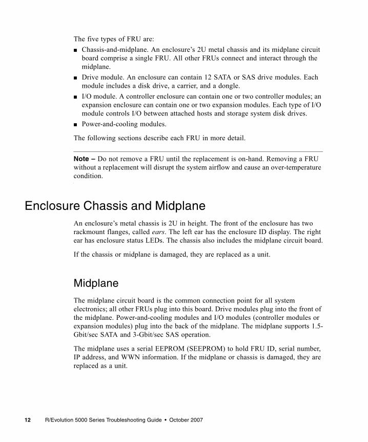
The five types of FRU are:■ Chassis-and-midplane. An enclosure’s 2U metal chassis and its midplane circuit
board comprise a single FRU. All other FRUs connect and interact through the midplane.
■ Drive module. An enclosure can contain 12 SATA or SAS drive modules. Each module includes a disk drive, a carrier, and a dongle.
■ I/O module. A controller enclosure can contain one or two controller modules; an expansion enclosure can contain one or two expansion modules. Each type of I/O module controls I/O between attached hosts and storage system disk drives.
■ Power-and-cooling modules.
The following sections describe each FRU in more detail.
Note – Do not remove a FRU until the replacement is on-hand. Removing a FRU without a replacement will disrupt the system airflow and cause an over-temperature condition.
Enclosure Chassis and MidplaneAn enclosure’s metal chassis is 2U in height. The front of the enclosure has two rackmount flanges, called ears. The left ear has the enclosure ID display. The right ear has enclosure status LEDs. The chassis also includes the midplane circuit board.
If the chassis or midplane is damaged, they are replaced as a unit.
Midplane
The midplane circuit board is the common connection point for all system electronics; all other FRUs plug into this board. Drive modules plug into the front of the midplane. Power-and-cooling modules and I/O modules (controller modules or expansion modules) plug into the back of the midplane. The midplane supports 1.5-Gbit/sec SATA and 3-Gbit/sec SAS operation.
The midplane uses a serial EEPROM (SEEPROM) to hold FRU ID, serial number, IP address, and WWN information. If the midplane or chassis is damaged, they are replaced as a unit.

Chapter 1 System Architecture 13
Enclosure ID Display
The enclosure ID (EID) display provides a visual single-digit identifier for each enclosure in a storage system. The EID display is located on the left ear, as viewed from the front of the chassis.
For a storage system that includes a controller module, EID values are set by the RAID controller. For expansion enclosures that are attached to a host for use as JBODs (just a bunch of disks), EID values are set by the host.■ When expansion enclosures are attached to a controller enclosure:
■ The controller enclosure’s EID is zero.■ An expansion enclosure’s EID is nonzero. The EID is 1 for the first expansion
enclosure, and the EID is incremented for each subsequent enclosure.■ EIDs are persistent, so will not change during simple reconfigurations. ■ EIDs can be used to correlate physical enclosures with logical views of the
storage system provided by system interfaces such as RAIDar.■ When expansion enclosures are attached to a host:
■ An expansion enclosure’s EID can be zero or nonzero.■ Each expansion enclosure in a storage system must have a unique EID. ■ EIDs are persistent, so will not change during simple reconfigurations. ■ EIDs can be used to correlate physical enclosures with logical views of the
storage system provided by system interfaces.
EIDs are managed by SES functions of the Expander Controller in each controller module and expansion module.
For information about how EIDs are affected when expansion modules are moved, see “Moving a Set of Expansion Modules” on page 94.

14 R/Evolution 5000 Series Troubleshooting Guide • October 2007
Drive ModulesA drive module is a FRU that has three components: the carrier (or sled), disk drive, and dongle board as shown in the following figure. The carrier has a front bezel with a lever that is used to insert or remove the drive module. When any component of a drive module fails, the entire module is replaced.
Figure 1-2 Drive Module
Each drive module is inserted into a drive slot (or bay) in an enclosure. The following figure shows the numbering of drive slots in an enclosure.
Figure 1-3 Drive Slot Numbers
A drive is identified by the numbers of the enclosure and slot that the drive is in. For example, the last drive in the controller enclosure is identified as 0.11 (EID 0, slot 11). Drive modules are slot-independent; that is, the drives can be moved to any slot with the power off. Once power is applied, the RAID controllers use the metadata held on each disk to locate each member of a virtual disk.
Dongle
Disk drive
Carrier
Chapter 1 System Architecture 15
Disk Drives
Each RAID controller has single-port access from the local SAS expander to internal and expansion enclosure drives. Alternate path, dual-port access to all internal drives is accomplished through the expander inter-controller wide lane connection. Dual-port access assumes the presence of both controller modules. In a failed-over configuration, where the partner controller module is down or removed, only single-port access to the drives exists.
The storage system can include either SAS or SATA drives, or both. Native command queuing (NCQ) is supported on SATA drives.
A drive can be interchanged with a qualified equivalent drive. In addition, each enclosure can be populated with disks of various capacities. To ensure the full use of a disk’s capacity, construct all virtual disks with disks of the same capacity.
Drive Module Dongle
Each drive module has a dongle board mounted to the rear. The type of board and purpose of the dongle depends upon the type of drive installed in the drive module. The dongle has an FC drive mechanically compatible SCA-II 40-pin connector that mates to the midplane. Other common components include power switching FETs, drive fault/activity LEDs and a simple microcontroller that is used to decode a single-wire serial interface from each controller.
SAS Drive Dongle
Because the SAS drives are natively dual-ported and can fully use the dual-path R/Evolution architecture, the SAS dongle board only serves to make the drive module connector compatible with the enclosure midplane.
SATA Drive Dongle
The single-ported SATA drive’s dongle board is used to make it connector-compatible with the midplane and includes an active/active (AA) multiplexer (MUX). The SATA AA MUX enables a single-port drive to appear as a dual port on the midplane.

16 R/Evolution 5000 Series Troubleshooting Guide • October 2007
FC Controller ModuleThe controller module is a single hot-pluggable board that mates with the enclosure midplane using a 150-pin midplane connector and provides all RAID functions and SAS expansion (drive) channels. It can accept a variety of plug-in mezzanine boards, known as host interface modules (HIMs). Currently the only HIM available is the Fibre Channel HIM. It is important to note that the host mezzanine is not a FRU. Together, a RAID I/O board and HIM form the controller module FRU.
The midplane connector interface supports high-speed serial lanes operating at up to 4-Gbit/sec link speed. The controller module has four mezzanine connectors to support the HIM and contains the Storage Controller, Expander Controller, Management Controller, SAS data paths, and SES processing functions.
Storage Controller
The Storage Controller (SC) consists of a Mobile Turion processor subsystem that provides all RAID functionality. It features 2.0 GHz core frequency options, 25 watt maximum power with 8 watt speed stepping option, 64 Kbyte L1 data on-die cache, 64 Kbyte L1 instruction on-die cache and 1 Mbyte L2 on-die cache options.
The SC also provides the bridging functionality that takes a Fibre Channel signal and sends out a SAS signal to the back end drive bus.
Expander Controller
The Expander Controller (EC) processes all SAS back-end expander operation and enclosure management functions. The EC is responsible for the PHY zoning.
Management Controller
The Management Controller (MC) subsystem provides all out-of-band management features, including the web-based interface (RAIDar), SNMP, CLI, DMS and e-mail notification. The MC also includes the external serial ports and Ethernet ports.
Host Interface Module
The following figure shows a block diagram of the FC HIM in a 5730 controller module.

Chapter 1 System Architecture 17
Figure 1-4 Block Diagram of the FC HIM Board
Controller Module Block Diagram
There are two primary processors: the SC and the MC. Both CPUs are independent, and one will operate if the other goes down. In addition, by having two CPUs, management functions have significantly less impact on RAID I/O performance.
As illustrated in Figure 1-5, the controller module includes a number of high-speed serial interfaces:■ SAS/SATA serial back-end disk channels (12 lanes per controller)■ SAS inter-controller alternate path (4 lanes)■ SAS disk channel expansion (4 lanes)
XX
PCIX bus 1 Controller 1
SRAM OSC
HIM
Connector
SRAM
HIM
Connector
SFF0
Serial H
IM C
onnector
PBC-0
PBC-1Port 2
Port 1
FC RX (Other PBC-1)FC RX (Other PBC-0)FC RX (Other PBC-3)FC RX (Other PBC-2)FC TX (Other PBC-1)FC TX (Other PBC-0)FC TX (Other PBC-3)FC TX (Other PBC-2)
MU
PCIX bus 2
SFF1
SFF2
SFF3
Lane cross-over on midplane
SRAM OSCSRAM
SC I2C
Repeater
PBC-2
PBC-3
HIM
Connector
Controller 2
Port 2
Port 1

18 R/Evolution 5000 Series Troubleshooting Guide • October 2007
■ PCI Express inter-controller messaging and write cache mirroring (4 lanes)■ FC serial front-end host channels (4 ports per controller)
Two FC serial connections between controllers used to facilitate controller failover (up to 4 lanes)
Figure 1-5 Block Diagram of the Controller Module
SAS Data Path
The back-end data path of each controller module uses the SAS protocol. To accomplish this, the controller module incorporates a number of SAS components as shown in the following figure.
Module A
ManagementController
SASx4
SAS x4
DiskExp 1
DiskExp 2
SATADrives
BA
Dongle
HIModd/even lanecross-over x 4
SAS/SATA x12
PC
IX 2
PC
IX 1
PCIX 2
PCIX 1SAS
ExpanderSASController
SASControllerStorage
Controller
PCI Express x4
SAS x4
SAS x4
SASx4
IOController
Host Connectors HIM
Host Serial Connectivity
IOController
Module B
ManagementController
SASx4
SAS x4
DiskExp 1
DiskExp 2
SAS/SATA x12
PC
IX 2
PC
IX 1
PCIX 2
PCIX 1SAS
Expander SASController
SASController Storage
Controller
SAS x4
SASx4
IOController
Host ConnectorsHIM
Host Serial Connectivity
IOController

Chapter 1 System Architecture 19
Figure 1-6 SAS Data Path
Module A
ManagementController
SASx4
SAS x4
DiskExp 1
DiskExp 2
SATADrives
BA
Dongle
HIModd/even lanecross-over x 4
SAS/SATA x12
PC
IX 2
PC
IX 1
PCIX 2
PCIX 1SAS
ExpanderSASController
SASControllerStorage
Controller
PCI Express x4
SAS x4
SAS x4
SASx4
IOController
Host Connectors HIM
Host Serial Connectivity
IOController
Module B
ManagementController
SASx4
SAS x4
DiskExp 1
DiskExp 2
SAS/SATA x12
PC
IX 2
PC
IX 1
PCIX 2
PCIX 1SAS
Expander SASController
SASController Storage
Controller
SAS x4
SASx4
IOController
Host ConnectorsHIM
Host Serial Connectivity
IOController
Disk data path

20 R/Evolution 5000 Series Troubleshooting Guide • October 2007
Power-and-Cooling ModulesEach enclosure contains two power-and-cooling modules. A power-and-cooling module is a FRU that includes a power supply unit and two cooling fans. If a power supply fault or fan fault occurs, the entire module is replaced.
Power Supply Unit
Each 750-Watt, AC power supply unit (PSU) is auto-sensing and runs in a load-balanced configuration to ensure that the load is distributed evenly across both power supplies.
Cooling Fans
The cooling fans are integrated into each of the power-and-cooling module FRUs. Each module contains two fans mounted in series. The fans are powered from the +12V common rail so that a single failed power supply still enables all fans to continue to operate.
The fans cannot be accidentally removed as they are part of the power-and-cooling module. Removing this module requires the disengagement of a captive panel fastener and the operation of an ejector lever to remove it from the chassis.
Should one fan fail in either module, the system continues to operate indefinitely. In addition, the fan system enables the airflow pattern to remain unchanged and there is no pressure leak through the failed fan since there are always two fans in tandem, and they are sealed to each other through a calibrated cavity. Should a power-and-cooling module be turned off or unplugged, the fans inside the module continue to operate at normal capacity. This is accomplished by powering each fan from a power bus on the midplane.
The fans’ variable speed is controlled by the controller modules through an I2C interface. The fans also provide tachometer speed information through the I2C interface. Speed control is accomplished through the use of speed commands issued from the controller module. The controller module has one temperature sensor at the inlet port of the controller to sense the exhaust air temperature from the disk drives. Should the controller module sense a rise in temperature, it can increase fan speed to keep the disk drive temperatures within limits.

Chapter 1 System Architecture 21
Balanced cooling for all of the drives is accomplished through the use of two mechanisms.■ Tuned port apertures in the midplane placed behind each drive carrier slot■ The use of a cavity behind the entire surface of the midplane (side-to-side and
top-to-bottom) that acts as an air pressure equalization chamber. This chamber is commonly evacuated by all of the fans.
In this way the amount of mass flow through each drive slot is controlled to be the same from slot to slot.
Airflow is controlled and optimized over the power supply by using the power supply chassis as the air-duct for the power supply, ensuring that there are no dead air spaces in the power supply core and increasing the velocity flow (LFM) by controlling the cross-sectional area that the mass flow travels through.
Airflow is controlled and optimized over the RAID I/O board and HIM in a similar manner. The controller cover is used as an air duct to force air over the entire surface of the controller from front to back, ensuring no dead air spaces, and increasing the velocity flow (LFM) by controlling the cross-sectional area that the mass flow travels through.
Cooling for all hot components is passive. There are no other fans in the system other than the fans contained in the power-and-cooling module.

22 R/Evolution 5000 Series Troubleshooting Guide • October 2007
Airflow
Caution – To allow for correct airflow and cooling, use an air management module for removed FRUs. Do not leave a FRU out of its slot for more than two minutes.
As noted above, an enclosures cooling system includes four fans in a tandem parallel array. These variable speed fans provide low noise and high mass flow rates. Airflow is from front to back. Each drive slot draws ambient air in at the front of the drive, sending air over the drive surfaces and then through tuned apertures in the chassis midplane.
Note that the airflow washes over the top and bottom surface of the disk drive at high mass flow and velocity flow rates, so both sides of the drive are used for cooling. The airflow system uses a cavity in the chassis behind the midplane as an air-pressure equalization chamber to normalize the negative pressure behind each of the disk drive slots. This mechanism together with the tuned apertures in the midplane behind each drive assures an even distribution of airflow and therefore LFM for each drive slot. This even cooling extends the operational envelope of the system by ensuring no “hot” drive bypass.
Further, airflow is “in line” with the top and bottom surfaces of the drive to reduce back-pressure and optimize fan performance. All of the mass flow at room ambient is used for cooling the 12 disk drives. The high velocity flow helps to lower the thermal resistance of the disk drive assembly to ambient temperature. The thermal temperature rise of the disk drive is dependent upon the power consumed by the disk drive, which varies by drive model as well as the level of drive activity.
23
CHAPTER 2
Fault Isolation Methodology
The R/Evolution storage system provides many ways to isolate faults within the system. This chapter presents the basic methodology used to locate faults and the associated FRUs.
The basic fault isolation steps are:■ Gather fault information.■ Determine where in the system the fault is occurring.■ Review event logs.■ If required, isolate the fault to a data path component.
Gather Fault Information
When a fault occurs, it is important to gather as much information as possible. Doing so will help you determine the correct action needed to remedy the fault.
Begin by reviewing the reported fault. Is the fault related to an internal data path or an external data path? Is the fault related to a hardware component such as a drive module, controller module, or power-and-cooling module? By isolating the fault to one of the components within the storage system, you will be able to determine the necessary action more rapidly.
Determine Where the Fault Is Occurring
Once you have an understanding of the reported fault, review the enclosure LEDs. The enclosure LEDs are designed to alert users of any system faults and might be what alerted the user to a fault in the first place.
When a fault occurs, the status LEDs on an enclosure’s right ear (see Figure 3-1) illuminate. Check the LEDs on the back of the enclosure to narrow the fault to a FRU, connection, or both. The LEDs also help you identify the location of a FRU reporting a fault. For more information about LEDs, see “Troubleshooting Using System LEDs” on page 25.

24 R/Evolution 5000 Series Troubleshooting Guide • October 2007
Use RAIDar to verify any faults found while viewing the LEDs. RAIDar is also a good tool to use in determining where the fault is occurring if the LEDs cannot be viewed due to the location of the system. RAIDar provides you with a visual representation of the system and where the fault is occurring. It can also provide more detailed information about FRUs, data, and faults.
Review the Event Logs
The event logs record all system events. It is very important to review the logs, not only to identify the fault, but also to search for events that might have caused the fault to occur. For example, a host could lose connectivity to a virtual disk if a user changes channel settings without taking the storage resources assigned to it into consideration. In addition, the type of fault can help you isolate the problem to hardware or software. For more information about event logs, see “Troubleshooting Using Event Logs” on page 71.
Isolate the Fault
It might be necessary to further isolate a fault to a single hardware component. This is particularly true with data paths due to the number of components the data path consists of. For example, if a host-side data error occurs, it could be caused by any of the components in the data path: controller module, SFP, cable, switch, or data host. For more information about isolating faults, see “Troubleshooting Using System LEDs” on page 25.

25
CHAPTER 3
Troubleshooting Using System LEDs
The first step in troubleshooting your storage system is to check the status of its LEDs. System LEDs can help you identify the FRU that is experiencing a fault. This chapter includes the following topics:■ “LED Names and Locations” on page 25■ “Using LEDs to Check System Status” on page 27
LED Names and LocationsThis section identifies the LEDs in each FRU.
Figure 3-1 Enclosure and Drive Module LEDs
Drive status LEDs (top to bottom):
Enclosure ID Enclosure status LEDs (top to bottom):Unit Locator
Fault/Service RequiredFRU OK
Temperature FaultOK to RemovePower/Activity/Fault

26 R/Evolution 5000 Series Troubleshooting Guide • October 2007
Figure 3-2 5730 Controller Module LEDs
Figure 3-3 Expansion Module LEDs
Figure 3-4 Power-and-Cooling Module LEDs
10/100 BASE-T STATUS STATUSACTIVITY
DIRTYCLEAN
CACHECLI
Service
Host link statusHost link speed
Host activity
ExpansionCache status
Unit LocatorOK to Remove
FRU OKFault/Service Required
Ethernet link statusEthernet activity
port status
Service
0 0
Unit LocatorOK to Remove
FRU OKFault/Service Required
SAS Out port statusSAS Inport status
AC Power Good
DC Voltage/Fan Fault/Service Required

Chapter 3 Troubleshooting Using System LEDs 27
Using LEDs to Check System StatusCheck the enclosure status LEDs periodically or after you have received an error notification. If a yellow LED is on, the enclosure has experienced a fault or failure.
More than one of the LEDs might display a fault condition at the same time. For example, if a disk drive failed due to an exceedingly high ambient temperature, both the Temperature Fault LED and the Fault/Service Required LED indicate the fault. This functionality can help you determine the cause of a fault in a FRU.
The following topics describe what to do when an LED indicates a fault condition. For descriptions of all LED statuses, refer to the Getting Started Guide for your enclosure model.■ “Using Enclosure Status LEDs” on page 28■ “Using Drive Module LEDs” on page 28■ “Using Controller Module Host Port LEDs” on page 29■ “Using the Controller Module Expansion Port LED” on page 30■ “Using Ethernet Management Port LEDs” on page 32■ “Using Controller Module Status LEDs” on page 32■ “Using Power-and-Cooling Module LEDs” on page 33■ “Using Expansion Module LEDs” on page 33
28 R/Evolution 5000 Series Troubleshooting Guide • October 2007
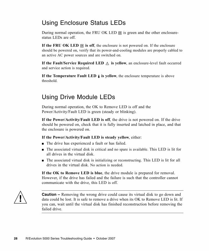
Using Enclosure Status LEDs
During normal operation, the FRU OK LED is green and the other enclosure-status LEDs are off.
If the FRU OK LED is off, the enclosure is not powered on. If the enclosure should be powered on, verify that its power-and-cooling modules are properly cabled to an active AC power sources and are switched on.
If the Fault/Service Required LED is yellow, an enclosure-level fault occurred and service action is required.
If the Temperature Fault LED is yellow, the enclosure temperature is above threshold.
Using Drive Module LEDs
During normal operation, the OK to Remove LED is off and the Power/Activity/Fault LED is green (steady or blinking).
If the Power/Activity/Fault LED is off, the drive is not powered on. If the drive should be powered on, check that it is fully inserted and latched in place, and that the enclosure is powered on.
If the Power/Activity/Fault LED is steady yellow, either:■ The drive has experienced a fault or has failed. ■ The associated virtual disk is critical and no spare is available. This LED is lit for
all drives in the virtual disk. ■ The associated virtual disk is initializing or reconstructing. This LED is lit for all
drives in the virtual disk. No action is needed.
If the OK to Remove LED is blue, the drive module is prepared for removal. However, if the drive has failed and the failure is such that the controller cannot communicate with the drive, this LED is off.
Caution – Removing the wrong drive could cause its virtual disk to go down and data could be lost. It is safe to remove a drive when its OK to Remove LED is lit. If you can, wait until the virtual disk has finished reconstruction before removing the failed drive.

Chapter 3 Troubleshooting Using System LEDs 29
Using Controller Module Host Port LEDs
During normal operation, when a controller module host port is connected to a data host, the port’s host link status LEDs are green. If the link speed is set to 2 Gbit/sec the host link speed LED is off; for 4 Gbit/sec, it is green. If there is I/O activity, the host activity LED blinks green.
If data hosts are having trouble accessing the storage system, check the following.
If the host link status LED is green but the host link speed LED indicates the wrong speed, in RAIDar select Manage > General Config > Host Port Configuration and set the proper link speed.
If a connected port’s host link status LED is off, the link is down. In RAIDar, review the event logs for indicators of a specific fault in a host data path component. If you cannot locate a specific fault or cannot access the event logs, use the procedure to isolate the fault as explained in “Isolating a Host-Side Connection Fault on the 5730” on page 29.
Isolating a Host-Side Connection Fault on the 5730
This procedure requires scheduled downtime.
Note – Do not perform more than one step at a time. Changing more than one variable at a time can complicate the troubleshooting process.
1. Halt all I/O to the storage system.
2. Check the host activity LED.If there is activity, halt all applications that access the storage system.
3. Reseat the FC cable.Is the host link status LED on? ■ Yes – Monitor the status to ensure that there is no intermittent error present. If
the fault occurs again, clean the connections to ensure that a dirty connector is not interfering with the data path.
■ No – Proceed to the next step.
4. Move the cable to a port with a known good link status.This step isolates the problem to the external data path (host cable and host-side devices) or to the controller module port.Is the host link status LED on?

30 R/Evolution 5000 Series Troubleshooting Guide • October 2007
■ Yes – You now know that the host cable and host-side devices are functioning properly. Return the cable to the original port. If the link status LED remains off, you have isolated the fault to the controller module’s port. Replace the controller module.
■ No – Proceed to the next step.
5. Swap the cable with a known good one.Is the host link status LED on?■ Yes – You have isolated the fault to the cable. Replace the cable.■ No – Proceed to the next step.
6. Replace the HBA with a known good HBA, or move the host-side cable to a known good HBA.Is the host link status LED on?■ Yes – You have isolated the fault to the HBA. Replace the HBA.■ No – It is likely that the controller module needs to be replaced.
7. Move the cable back to its original port.Is the host link status LED on?
■ No – The controller module’s port has failed. Replace the controller module.■ Yes – Monitor the connection for a period of time. It may be an intermittent
problem, which can occur with damaged cables and HBAs.
Using the Controller Module Expansion Port LED
During normal operation, when a controller module’s expansion port is connected to an expansion enclosure, the expansion port status LED is green.
If the connected port’s LED is off, the link is down. In RAIDar, review the event logs for indicators of a specific fault. If you cannot locate a specific fault or cannot access the event logs, use the following procedure to isolate the fault.
This procedure requires scheduled downtime.
Note – Do not perform more than one step at a time. Changing more than one variable at a time can complicate the troubleshooting process.

Chapter 3 Troubleshooting Using System LEDs 31
1. Halt all I/O to the storage system.
2. Check the host activity LED.If there is activity, halt all applications that access the storage system.
3. Reseat the expansion cable.Is the expansion port status LED on?■ Yes – Monitor the status to ensure there is no intermittent error present. If the
fault occurs again, clean the connections to ensure that a dirty connector is not interfering with the data path.
■ No – Proceed to Step 4.
4. Move the expansion cable to a port on the RAID enclosure with a known good link status.This step isolates the problem to the expansion cable or to the controller module’s expansion port. Is the expansion port status LED on?
■ Yes – You now know that the expansion cable is good. Return cable to the original port. If the expansion port status LED remains off, you have isolated the fault to the controller module’s expansion port. Replace the controller module.
■ No – Proceed to the next step.
5. Move the expansion cable back to the original port on the controller enclosure.
6. Move the expansion cable on the expansion enclosure to a known good expansion port on the expansion enclosure. Is the expansion port status LED on?■ Yes – You have isolated the problem to the expansion enclosure’s port. Replace
the expansion module. ■ No – Proceed to Step 7.
7. Replace the cable with a known good cable, ensuring the cable is attached to the original ports used by the previous cable.Is the host link status LED on?■ Yes – Replace the original cable. The fault has been isolated.■ No – It is likely that the controller module needs to be replaced.

32 R/Evolution 5000 Series Troubleshooting Guide • October 2007
Using Ethernet Management Port LEDs
During normal operation, when a controller module’s Ethernet management port is connected, its Ethernet link status LED is green. If there is I/O activity, the host activity LED blinks green.
If a management host is having trouble accessing the storage system, check the following.
If a connected port’s Ethernet link status LED is off, the link is down. Use standard networking troubleshooting procedures to isolate faults on the network.
Using Controller Module Status LEDs
During normal operation, the FRU OK LED is green, the cache status LED can be green or off, and the other controller module status LEDs are off.
If the FRU OK LED is off, either:■ The controller module is not powered on. If it should be powered on, check that
it is fully inserted and latched in place, and that the enclosure is powered on.■ The controller module has failed. Check the event log for specific information
regarding the failure.
If the Fault/Service Required LED is steady yellow, a fault occurred or service action is required.
If the Cache status LED is blinking green, a cache flush or self-refresh is in progress. No action is needed.■ If the LED is blinking evenly, a cache flush is in progress. When a controller
module loses power and write cache is dirty (contains data that has not been written to disk), the super-capacitor pack provides backup power to flush (copy) data from write cache to Compact Flash memory. When cache flush is complete, the cache transitions into self-refresh mode.
■ If the LED is blinking slowly, a cache flush is in progress. In self-refresh mode, if primary power is restored before the backup power is depleted (3–30 minutes depending on various factors), the system boots, finds data preserved in cache, and writes it to disk. This means the system can be operational within 30 seconds, and before the typical host I/O timeout of 60 seconds at which point system failure would cause host-application failure. If primary power is restored after the backup power is depleted, the system boots and restores data to cache from Compact Flash, which can take about 90 seconds.

Chapter 3 Troubleshooting Using System LEDs 33
Note – The cache flush and self-refresh mechanism is an important data protection feature; essentially four copies of user data are preserved: one in each controller's cache and one in each controller's Compact Flash.
If the Fault/Service Required LED is blinking yellow, one of the following errors occurred:■ Hardware-controlled power-up error ■ Cache flush error ■ Cache self-refresh error
If the OK to Remove LED is blue, the controller module is prepared for removal.
Using Power-and-Cooling Module LEDs
During normal operation, the AC Power Good LED is green.
If the AC Power Good LED is off, the module is not receiving adequate power. Verify that the power cord is properly connected and check the power source it is connected to.
If the DC Voltage/Fan Fault/Service Required LED is yellow, the power supply unit or a fan is operating at an unacceptable voltage/RPM level, or has failed. When isolating faults in the power-and-cooling module, remember that the fans in both modules receive power through a common bus on the midplane so if a power supply unit fails, the fans continue to operate normally.
Using Expansion Module LEDs
During normal operation, when the expansion module is connected to a controller module or a host, the SAS In port status LED is green. If the SAS Out port is connected to another expansion module, the SAS Out port status LED is also green. The other LEDs are off.
If a connected port’s status LED is off, the link is down. In RAIDar, review the event logs for indicators of a specific fault in a host data path component.

34 R/Evolution 5000 Series Troubleshooting Guide • October 2007
If the FRU OK LED is off, either:■ The expansion module is not powered on. If it should be powered on, check that
it is fully inserted and latched in place, and that the enclosure is powered on.■ The expansion module has failed. Check the event log for specific information
regarding the failure.
If the Fault/Service Required LED is steady yellow, a fault occurred or service action is required.
If the Fault/Service Required LED is blinking yellow, one of the following errors occurred:■ Hardware-controlled power-up error ■ Cache flush error ■ Cache self-refresh error
35
CHAPTER 4
Troubleshooting Using RAIDar
This chapter describes how to use RAIDar to troubleshoot your storage system and its FRUs. It also describes solutions to problems you might experience when using RAIDar.
Topics covered in this chapter include:■ “Determining Storage System Status and Verifying Faults” on page 36■ “Stopping I/O” on page 37■ “Isolating Faulty Disk Drives” on page 39■ “Isolating Data Path Faults” on page 44■ “Isolating Disk Drive Faults” on page 50■ “Clearing Metadata From Leftover Disk Drives” on page 51■ “Using Diagnostic Functions” on page 52■ “Using Recovery and Debug Utilities” on page 63■ “Problems Using RAIDar to Access a Storage System” on page 66■ “Problems Scheduling Tasks” on page 67
Note – You can also use the CLI to troubleshoot your storage system. “Troubleshooting Using the CLI” on page 143 provides information on specific CLI commands that can be used to troubleshoot your system.

36 R/Evolution 5000 Series Troubleshooting Guide • October 2007
Determining Storage System Status and Verifying Faults
The System Summary page shows you the overall status of the storage system. System preferences might be set to display this page when you log in, otherwise you can select it from the menu.
To view storage system status:
1. Select Monitor > Status > Status Summary.
2. Check the status icon at the upper left corner of each panel.■ A green icon indicates that components associated with that panel are
operating normally. ■ A red icon with an exclamation point indicates that at least one component
associated with that panel has a fault and is operating in a degraded state or is offline.
Figure 4-1 Status Summary Page with a Fault Identified by Status Icons
3. Review each panel that has a fault icon.

Chapter 4 Troubleshooting Using RAIDar 37
4. Look for red text in the panels.Red text indicates where the fault is occurring. In Figure 4-1 for example, the panels indicate a fault related to controller module B.
5. To gather more details regarding the failure, click linked text next to the fault icon.The associated status page is displayed.
6. Review the information displayed in the status page.If the fault relates to a controller module or power module, an image of the enclosure is displayed.■ The module is shaded red if it has a fault or is powered off.■ The module is overlaid with the words “NOT INSTALLED” if it is absent or not
fully inserted.
Stopping I/OWhen troubleshooting drive and connectivity faults, ensure that you have a current full backup. As an additional data protection precaution, stop all I/O to the affected virtual disks. When on-site, you can verify that there is no I/O activity by briefly monitoring the system LEDs; however, when accessing the storage system remotely, this is not possible.
To check the I/O status of a remote system, use the Monitor > Statistics > Overall Rate Stats page. The Overall Rate Stats page enables you to view I/O based on the host-side activity interval since the page was last refreshed. The page automatically refreshes at a 60-second interval. The following data is presented for all virtual disks:■ The total IOPS and bandwidth for all virtual disks■ The IOPS and bandwidth for each virtual disk

38 R/Evolution 5000 Series Troubleshooting Guide • October 2007
To use the Overall Rate Stats page to ensure that all I/O has ceased on a remote system:
1. Quiesce host applications that access the storage system.
2. Select Monitor > Statistics > Overall Rate Stats.
3. Click your browser’s refresh button to ensure that current data is displayed.
4. In the Host-Generated I/O & Bandwidth Totals for All Virtual Disks panel, verify that both indicators display 0 (no activity).

Chapter 4 Troubleshooting Using RAIDar 39
Isolating Faulty Disk DrivesWhen a drive fault occurs, basic troubleshooting actions include:■ Identifying the faulty drive■ Reviewing the drive error statistics■ Reviewing the event log■ Replacing the faulty drive■ Reconstructing the associated virtual disk
Identifying a Faulty Disk Drive
The identification of a faulty disk drive involves confirming the drive fault and identifying the physical location of the drive.
To confirm a drive fault, use the basic troubleshooting steps in “Determining Storage System Status and Verifying Faults” on page 36. You can also navigate to the Monitor > Status > Show Notification page and look for any notifications pertaining to a disk drive fault.
When you have confirmed a drive fault, record the drive’s enclosure number and slot number.
To identify the physical location of a faulty drive:
1. Select Manage > Utilities > Disk Drive Utilities > Locate Disk Drive.
2. Select the faulty drive.If the drive is absent or not fully inserted, it is represented with a white rectangle and is not selectable, as shown in the following example.
3. Click Update LED Illumination.The lower LED on the selected drive starts blinking yellow.
For more information about viewing drive information, refer to the Administrator’s Guide.

40 R/Evolution 5000 Series Troubleshooting Guide • October 2007
Reviewing Disk Drive Error Statistics
The Disk Error Stats page provides specific drive fault information. It shows a graphical representation of the enclosures and disks installed in the system. The Disk Error Stats page can be used to gather drive information and to identify specific drive errors. Additionally, you can capture intermittent errors.
To view the disk drive error statistics:
1. Select Monitor > Statistics > Disk Error Stats.The top panel displays all enclosures and drives in the storage system.
2. Select the drive whose error statistics you want to view.
3. Click Show Disk Drive Error Statistics.The drive error data for the selected disk is displayed in the second panel.
4. Note any error counts displayed for these statistics.
Field Description
SMART Event Count The number of SMART (Self-Monitoring, Analysis, and Reporting Technology) events that the drive recorded. These events are often used by the drive vendor to determine the root cause of a drive failure. Some SMART events may indicate imminent electromechanical failure.
I/O Timeout Count The number of times the drive accepted an I/O request but did not complete it in the required amount of time. Excessive timeouts can indicate potential device failure (media retries or soft, recoverable errors)
No Response Count The number of times the drive failed to respond to an I/O request. A high value can indicate that the drive is too busy to respond to further requests.
Spin-up Retries The number of times the drive failed to start on power-up or on a software request. Excessive spin-up retries can indicate that a drive is close to failing.
Media Errors The number of times the drive had to retry an I/O operation because the media did not successfully record or retrieve the data correctly.

Chapter 4 Troubleshooting Using RAIDar 41
Capturing Error Trend Data
To capture error trend data for one or more drives:
1. Perform the procedure in “Reviewing Disk Drive Error Statistics” on page 40.
2. Create a baseline by clearing the current error statistics.To clear the statistics for one drive, select the drive and click Clear Selected Disk Drive Error Statistics. To clear the statistics for all drives, click Clear All Disk Drive Error Statistics. You cannot clear the Bad Block List Size statistic.If a faulty drive is present, errors are captured in a short period of time. If the drive has intermittent errors you might have to monitor the storage system for more than 24 hours.
3. To view the error statistics, select the suspected drive and click Show Disk Drive Error Statistics.
4. Review the Disk Drive Error Statistics panel for drive errors. The Disk Drive Error Statistics panel enables you to review errors from each of the two ports.
Non Media Errors The number of soft, recoverable errors that are not associated with drive media.
Bad Block Reassignments The number of block reassignments that have taken place since the drive was shipped from the vendor. A large number of reallocations in a short period of time could indicate a serious condition.
Bad Block List Size The number of blocks that have been deemed defective either from the vendor or over time due to reallocation.
Field Description

42 R/Evolution 5000 Series Troubleshooting Guide • October 2007
Reviewing the Event Logs
If all the steps in “Identifying a Faulty Disk Drive” on page 39 and “Reviewing Disk Drive Error Statistics” on page 40 have been performed, you have determined the following:■ A disk drive has encountered a fault ■ The location of the disk drive ■ What the fault is
The next step is to review the event logs to determine if there were any events that led to the fault. If you skip this step, you could replace the faulty drive and then encounter another fault.
To view the event logs from any page, click the icon in the System Panel. See “Troubleshooting Using Event Logs” on page 71 for more information about using event logs.

Chapter 4 Troubleshooting Using RAIDar 43
Reconstructing a Virtual Disk
If one or more drives fail in a redundant virtual disk (RAID 1, 3, 5, 6, 10, or 50) and properly sized spares are available, the storage system automatically uses the spares to reconstruct the virtual disk. Virtual disk reconstruction does not require I/O to be quiesced, so the virtual disk can continue to be used while the Reconstruct utility runs.
A properly sized spare is one whose capacity is equal to or greater than the smallest drive in the virtual disk. If no properly sized spares are available, reconstruction does not start automatically. To start reconstruction manually, replace each failed drive and then do one of the following:■ Add each new drive as a vdisk spare (Manage > Virtual Disk Config > Vdisk
Configuration > Add Vdisk Spares) or a global spare (Manage > Virtual Disk Config > Global Spare Menu > Add Global Spares). Remember that a global spare might be taken by a different critical virtual disk than the one you intended.
■ Enable the Dynamic Spare Configuration option on the Manage > General Config > System Configuration page to use the new drives without designating them as spares.
When two drives have failed, reconstructing a RAID-6 virtual disk to a fault-tolerant state requires two properly sized spares to be available.■ If two drives fail and only one properly sized spare is available, the virtual
disk will remain in a Critical state until a second properly sized spare is available. The Reconstruct utility will start to run when two properly sized spares are available.
■ If a drive fails during online initialization, the initialization fails. To generate the two sets of parity that RAID 6 requires, the controller fails a second drive in the virtual disk, which changes the virtual disk status to Critical, and then assigns that disk as a spare for the virtual disk. If there is an available properly sized spare, a reconstruct will begin. If no properly sized spare is available, the virtual disk will remain in a Critical state until one becomes available to replace the original failed drive. The Reconstruct utility will start to run when two properly sized spares are available. Although a second drive was failed, only one replacement drive is required because the drive that was failed is reused as a spare.
For both cases noted above, the second available spare can be an existing global spare, another existing spare for the virtual disk, or a replacement drive that you designate as a spare or that is automatically taken when dynamic sparing is enabled.
44 R/Evolution 5000 Series Troubleshooting Guide • October 2007
During reconstruction, though the critical virtual disk icon is displayed, you can continue to use the virtual disk. When a global spare replaces a drive in a virtual disk, the global spare’s icon in the enclosure view changes to match the other drives in that virtual disk.
Note – Reconstruction can take hours or days to complete, depending on the virtual disk RAID level and size, drive speed, utility priority, and other processes running on the storage system. You can stop reconstruction only by deleting the virtual disk.
Isolating Data Path FaultsWhen isolating data path faults, you must first isolate the fault to an internal data path or an external data path. This will help to target your troubleshooting efforts.
Internal data paths include the following:■ Controller- to-disk connectivity■ Controller-to-controller connectivity■ Controller ingress (incoming signals from expansion enclosures)■ Controller egress (outgoing signals to expansion enclosures)
External data paths consist of the connections between the storage system and data hosts.
To troubleshoot a data path using RAIDar, do the following:■ Identify the fault as an internal or external data path fault using the steps in
“Determining Storage System Status and Verifying Faults” on page 36.■ Gather details about the fault.■ Review event logs.■ Replace the faulty component.
Isolating Internal Data Path Faults
A Physical Layer Interface (PHY) is an interface in a device used to connect to other devices. The term refers to the physical layer of the Open Systems Interconnect (OSI) basic reference model. The physical layer defines all of the electrical and physical specifications for a device.
In a SAS architecture, each physical point-to-point connection is called a lane. Every lane has a PHY at either end. Lanes are sometimes referred to as physical links.

Chapter 4 Troubleshooting Using RAIDar 45
Fault isolation firmware monitors hardware PHYs for problems.
PHYs are tested and verified before shipment as part of the manufacturing and qualification process. But subsequent problems can occur in a PHY because of installation problems such as:■ A bad cable between enclosures■ A controller connector that is damaged as a result of attaching a cable and then
torquing the cable connector until solder joints connecting the controller connector become fatigued or break
Problem PHYs can cause a host or controller to continually rescan drives, which disrupts I/O or causes I/O errors. I/O errors can result in a failed drive, causing a virtual disk to become critical or causing complete loss of a virtual disk if more than one fails.
To avoid these problems, problem PHYs are identified and disabled, if necessary, and status information is transmitted to the controller so that each action can be reported in the event log. Problem PHY identification and status information is reported in RAIDar.
Some PHY errors can be expected when powering on an enclosure, when removing or inserting a controller, and when connecting or disconnecting an enclosure. An incompletely connected or disturbed cable might also generate a PHY error. These errors are usually not significant enough to disable a PHY, so the fault isolation firmware analyzes the number of errors and the error rate. If errors for a particular PHY increase at a slow rate, the PHY is usually not disabled. Instead the errors are accumulated and reported.
On the other hand, bad cables connecting enclosures, damaged controller connectors, and other physical damage can cause continual errors, which the fault isolation firmware can often trace to a single problematic PHY. The fault isolation firmware recognizes the large number and rapid rate of these errors and disables this PHY without user intervention. This disabling, sometimes referred to as PHY fencing, eliminates the I/O errors and enables the system to continue operation without suffering performance degradation.
Once the firmware has disabled a PHY, the only way to enable the PHY again is to reset the affected controller or power cycle the enclosure. Before doing so, it may be necessary to replace a defective cable or FRU.
If a PHY becomes disabled, the event log entry helps to determine which enclosure or enclosures and which controller (or controllers) are affected.

46 R/Evolution 5000 Series Troubleshooting Guide • October 2007
RAIDar provides an Expander Status page, which contains an Expander Controller Phy Detail panel. This panel shows information about each PHY in the internal data paths between the Storage Controller, Expander Controller, drives, and expansion ports. By reviewing this page you can quickly locate the internal data path that has a fault.
Checking PHY Status
RAIDar's Expander Status page includes an Expander Controller PHY Detail panel. This panel shows the internal data paths that show the data paths for the Storage Controller, Expander Controller, disks, and expansion ports. Review this page to locate an internal data path that has a fault.
To view expander status information:
1. Select Monitor > Status > Advanced Settings > Expander Status.
2. Select an enclosure.
The Enclosure Details panel shows the following information about the enclosure: name, vendor, location, status, enclosure ID, World Wide Name, model, rack and position numbers, and firmware version. For details, see the page help.
3. Review the Expander Controller Phy Detail panel.This panel shows the following information about each PHY:■ Status – Specifies one of the following:
■ OK – The PHY is healthy.■ Error – The PHY experienced an unrecoverable error condition or received an
unsupported PHY status value. ■ Disabled – The PHY has been disabled by a Diagnostic Manage user or by the
system.■ Non-Critical – The PHY is not coming to a ready state or the PHY at the other
end of the cable is disabled.■ Not Used – The module is not installed.
■ Type – Specifies one of the following:■ Disk – Communicates between the expander and a disk drive.■ Inter-Exp – (Controller module only) Communicates between the expander
and the partner’s expander.■ Ingress – Communicates between the EC and the expander.■ Egress – Communicates between the expander and an expansion port or SAS
Out port.

Chapter 4 Troubleshooting Using RAIDar 47
■ State – Specifies whether the PHY is enabled or disabled.■ ID – Identifies a PHY's logical location within a group based on the PHY type.
Logical IDs are 0–11 for disk PHYs and 0–3 for inter-expander, egress, and ingress PHYs.
■ Details – Pause the cursor over or click the information icon to view a popup with more information. If you click the icon, the information remains shown until the cursor passes over a similar icon.■ Status – The same status value shown in the panel's Status field.■ Physical Phy ID – Identifies a PHY's physical location in the expander.■ Type – The same type value shown in the panel's Type field.■ Phy Change Count – Specifies the number of times the PHY originated a
BROADCAST (CHANGE). A BROADCAST (CHANGE) is sent if doubleword synchronization is lost or at the end of a Link Reset sequence.
■ Code Violation Count – Specifies the number of times the PHY received an unrecognized or unexpected signal.
■ Disparity Error Count – Specifies the number of doublewords containing running disparity errors that have been received by the PHY, not including those received during Link Reset sequences. A running disparity error occurs when positive and negative values in a signal don't alternate.
■ CRC Error Count – In a sequence of SAS transfers (frames), the data is protected by a cyclic redundancy check (CRC) value. This error count specifies the number of times the computed CRC does not match the CRC stored in the frame, which indicates that the frame might have been corrupted in transit.
■ Inter-Connect Error Count – Specifies the number of times the lane between two expanders experienced a communication error.
■ Lost Doubleword Count – Specifies the number of times the PHY has lost doubleword synchronization and restarted the Link Reset sequence.
■ Invalid Doubleword Count – Specifies the number of invalid doublewords that have been received by the PHY, not including those received during Link Reset sequences.
■ Reset Error Count – Specifies the number of times the expander performed a reset.
■ Phy Disabled – Specifies whether the PHY is enabled (True) or disabled (False).
■ Fault Reason – A coded value that explains why the EC isolated the PHY. If the PHY is active, this value is 0x0.

48 R/Evolution 5000 Series Troubleshooting Guide • October 2007
When working with intermittent errors, you might want to reset PHY status so that you can observe error trend information. A Diagnostic Manage user can do this on the Expander Isolation page.
1. Select Manage > Utilities > Diagnostic Tools > Expander Isolation.The Expander Isolation page is similar to the Expander Status page, but enables you to reset expander error counters, manually disable or enable individual PHYs, and disable or enable PHY fault isolation.
2. Select an enclosure.
3. Note the PHY that is currently in error.
4. Click Clear Errors to reset PHY error counters.When the error recurs, review the Expander Controller Phy Detail page for any changes. The error counters display only the errors that occurred in the interval between the clearing PHY statuses and the current time.For more information about the Expander Isolation page, see “Changing Fault Isolation and PHY Settings” on page 62.
Reviewing the Event Log for Disabled PHYs
If the fault isolation firmware disables a PHY, the event log shows a message like the following:.
When a PHY has been disabled manually, the event log shows a similar message with a different reason:
Phy disabled. Enclosure:A00. Phy11. PhysId11 Type:Drive. Reason:Externally Disabled.
Phy disabled. Enclosure:A00. Phy11. PhysId11. Type:Drive. Reason:Ctrl Page Disabled.
Chapter 4 Troubleshooting Using RAIDar 49
Resolving PHY Faults
1. Ensure that the cables are securely connected. If they are not, tighten the connectors.
2. Reset the affected controller or power-cycle the enclosure.
3. If the problem persists, replace the affected FRU or enclosure.
4. Periodically examine the Expander Status page to see if the fault isolation firmware disables the same PHY again. If it does:
a. Replace the appropriate cable.
b. Reset the affected controller or power-cycle the enclosure.
Isolating External Data Path Faults on an FC Storage System
To troubleshoot external data path faults, perform the following steps:
1. Select Monitor > Status > Advanced Settings > Host Port Status. This page provides a graphical representation of controller host port status and port details.
2. Review the graphical representation of host port status.■ Green – Host link is up■ Red – Host link is down
An indication of link down can be caused by one or more of the following conditions:■ A faulty HBA in the host ■ A faulty Fibre Channel cable■ A faulty port in the host interface module■ A disconnected cable
3. To target the cause of the link failure, view the host port details by clicking on a port in the graphical view and then reviewing the details listed below it.The data displayed includes:■ Host Port Status Details – Selected controller and port number. ■ Receive Signal – Signal is present or not present. ■ Link Status – Link is up (active) or down (inactive). ■ Signal Detect – Signal is detected or no signal.

50 R/Evolution 5000 Series Troubleshooting Guide • October 2007
■ Topology – One of the following values:■ Point-to-Point■ Loop, if the loop is inactive■ Private Loop, if the port is directly attached to a host■ Public Loop, if the port is attached to a switch
■ Speed – 2 Gbit/sec or 4 Gbit/sec.■ FC Address – 24-bit FC address, or Unavailable if the FC link is not active.■ Node WWN – Controller module node World Wide Name. ■ Port WWN – Port World Wide Name.
Resetting a Host Channel on an FC Storage System
For a Fibre Channel system using FC-AL (loop) topology, you might need to reset a host link to fix a host connection or configuration problem. You can use this command to remotely issue a loop initialization primitive (LIP) on specified controller channels.
To reset host channels:
1. Select Manage > Utilities > Host Utilities > Reset Host Channel.
2. Set the channel and controller options.
3. Click Reset Host Channel.
Isolating Disk Drive FaultsFor information regarding the isolation of faults for disk drives see “Isolating Faulty Disk Drives” on page 39.

Chapter 4 Troubleshooting Using RAIDar 51
Clearing Metadata From Leftover Disk DrivesIf a disk drive’s metadata identifies it as part of a nonexistent virtual disk, the drive is considered a leftover. RAIDar reports the drive’s virtual disk as Leftover and shows the drive as follows in enclosure view:
The storage system uses metadata to identify virtual disk members after restarting or replacing enclosures. A drive becomes a leftover when it is removed from the enclosure where that drive is part of a virtual disk, and either the virtual disk is deleted and the drive is reinserted, or the drive is inserted in a different system.
Before you can use the drive a different virtual disk or as a spare, you must clear the metadata.
To clear metadata from drives:
1. Select Manage > Utilities > Disk Drive Utilities > Clear Metadata. An enclosure view is displayed in which only Leftover and Available drives are selectable. Available drives are considered to have had their metadata cleared, but are selectable in case a drive with partial metadata has been inserted into the system.
2. Select the drives whose metadata you want to clear.
3. Click Clear Metadata For Selected Disk Drives.

52 R/Evolution 5000 Series Troubleshooting Guide • October 2007
Using Diagnostic FunctionsTo use RAIDar functions covered in this section, you must be logged in as a Diagnostic Manage user. ■ “Trusting a Virtual Disk for Disaster Recovery” on page 52■ “Clearing Unwritable Cache Data” on page 54■ “Viewing the Debug Log” on page 54■ “Viewing Crash and Boot Data” on page 55■ “Viewing a CAPI Command Trace” on page 56■ “Viewing a Management Trace” on page 57■ “Selecting Individual Events for Notification” on page 58■ “Selecting or Clearing All Events for Notification” on page 59■ “Enabling Service Interfaces” on page 60■ “Restoring Management Controller Defaults Only” on page 61■ “Changing Fault Isolation and PHY Settings” on page 62
Trusting a Virtual Disk for Disaster Recovery
If a virtual disk appears to be down or offline (not quarantined) and its drives are labeled “Leftover,” use the Trust Virtual Disk function to recover the virtual disk. The Trust Virtual Disk function brings a virtual disk back online by ignoring metadata that indicates the drives might not form a coherent virtual disk. This function can force an offline virtual disk to be critical or fault-tolerant, or a critical virtual disk to be fault-tolerant. You might need to do this when:■ A drive was removed or was marked as failed in a virtual disk due to
circumstances you have corrected (such as accidentally removing the wrong disk). In this case, one or more drives in a virtual disk can start up more slowly, or might have been powered on after the rest of the drives in the virtual disk. This causes the date and time stamps to differ, which the storage system interprets as a problem. Also see “Dequarantining a Virtual Disk” on page 63.
■ A virtual disk is offline because a drive is failing, you have no data backup, and you want to try to recover the data from the virtual disk. In this case, the Trust Virtual Disk function might work, but only as long as the failing drive continues to operate.
Caution – If used improperly, the Trust Virtual Disk feature can cause unstable operation and data loss. Only use this function for disaster recovery purposes and when advised to do so by a service technician. When Trust Virtual Disk is enabled, the virtual disk has no tolerance for any additional failures.

Chapter 4 Troubleshooting Using RAIDar 53
To enable and use Trust Virtual Disk:
1. Select Manage > Utilities > Recovery Utilities > Enable Trust Virtual Disk.
2. Select Enabled.
3. Click Enable/Disable Trust Virtual Disk.The option remains enabled until you trust a virtual disk or restart the storage system.
4. Select Manage > Utilities > Recovery Utilities > Trust Virtual Disk.
5. Select the virtual disk and click Trust This Virtual Disk.
6. Back up the data from all the volumes residing on this virtual disk and audit it to make sure that it is intact.
7. Select Manage > Virtual Disk Config > Verify Virtual Disk. While the verify utility is running, any new data written to any of the volumes on the virtual disk is written in a parity-consistent way.
Note – If the virtual disk does not come back online, it might be that too many drives are offline or the virtual disk might have additional failures on the bus or enclosure that Trust Virtual Disk cannot fix.

54 R/Evolution 5000 Series Troubleshooting Guide • October 2007
Clearing Unwritable Cache Data
Unwritable cache data is data in the controller cache that cannot be written to a virtual disk because that virtual disk is no longer accessible. The virtual disk may be offline or missing. Unwritable cache data can exist if I/O to the virtual disk does not complete because drives or enclosures fail or are removed before the data can be written. Recovery is possible if the missing devices can be restored so that the cached data can be written to the virtual disk.
Unwritable cache data might affect performance because it ties up the cache space and prevents that space from being used by other virtual disks that might be performing I/O. The percentage of the cache filled with unwritable cache data is displayed. This data can be from one or multiple virtual disks. If the data is from only one virtual disk, then the serial number for this virtual disks is displayed. If the data is from multiple virtual disks, then only the serial number of one virtual disk is displayed. If the unwritable cache data for this virtual disk is cleared, then the serial number of the next virtual disk is displayed.
Caution – Make sure that the data is no longer needed before clearing it. Once unwritable cache data is cleared, it cannot be recovered.
To remove data from the cache:
1. Select Manage > Utilities > Recovery Utilities > Cache Data Status.
2. Click Clear Unwritable Cache Data.If there is unwritable cache data, this page specifies the percentage of both controllers' cache that this data occupies. Otherwise, the page shows that there is no unwritable cache data.
Note – Event log entries specify the percentage of the owning controller's cache that unwritable data occupies. Therefore in a dual-controller system, the percentage that the Cache Data Status page shows is half the percentage that the event log shows.
Viewing the Debug Log
To set up and view the debug log using RAIDar, see “Configuring the Debug Log” on page 75.
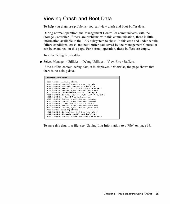
Chapter 4 Troubleshooting Using RAIDar 55
Viewing Crash and Boot Data
To help you diagnose problems, you can view crash and boot buffer data.
During normal operation, the Management Controller communicates with the Storage Controller. If there are problems with this communication, there is little information available to the LAN subsystem to show. In this case and under certain failure conditions, crash and boot buffer data saved by the Management Controller can be examined on this page. For normal operation, these buffers are empty.
To view debug buffer data:
● Select Manage > Utilities > Debug Utilities > View Error Buffers.If the buffers contain debug data, it is displayed. Otherwise, the page shows that there is no debug data.
To save this data to a file, see “Saving Log Information to a File” on page 64.

56 R/Evolution 5000 Series Troubleshooting Guide • October 2007
Viewing a CAPI Command Trace
To help you diagnose problems, you can view the Configuration API (CAPI) commands sent and received by the Management Controller. For example, if a command to create a virtual disk fails, the trace shows the request to create the virtual disk and the reason it failed. The View CAPI Trace page provides detail for the underlying action that supports the failed function.
The upper panel has the following fields:■ Requested Lines To Display – A selectable number of lines to display in the
trace. Allowed values are 50, 100, 200, 300, 400, 500 (all). The default is 200.■ CAPI Trace Snap Shot Time – The date and time when the trace was generated.■ Lines Displayed – The number of lines displayed in the trace, one greater than
the Requested Lines To Display value.■ CAPI Time Span – The times of the first and last commands in the trace.
The lower panel shows the trace data.
To view the CAPI trace:
● Select Manage > Utilities > Debug Utilities > View CAPI Trace.
The CAPI command trace data is displayed.
To update the trace data, click Load/Reload CAPI Command Trace. The trace data and related values in the upper panel are updated.
To save this data to a file, see “Saving Log Information to a File” on page 64.

Chapter 4 Troubleshooting Using RAIDar 57
Viewing a Management Trace
To help you diagnose problems, you can view a debug trace for the Management Controller (MC). It traces activity in the MC and between the MC and other controller processors.
To view the management trace:
1. Select Manage > Utilities > Debug Utilities > View Mgmt Trace.
2. Click Load/Reload Debug Trace.The LAN Debug Trace panel is displayed and the trace time is updated in the Management Controller Debug Trace panel.Because the debug trace can be large, only the most recent 100 entries are displayed.
To view all trace entries and save this data to a file, see “Saving Log Information to a File” on page 64.

58 R/Evolution 5000 Series Troubleshooting Guide • October 2007
Selecting Individual Events for Notification
As described in the Administrator’s Guide, you can configure how and under what conditions the storage system alerts you when specific events occur. In addition to selecting event categories, as a Diagnostic Manage user, you can select individual events that you want to be notified of.
Note – Selecting many individual events can result in the system sending numerous event notifications. Select the categories and individual events that are most important to you.
Use this method when you want to track or watch for a specific event. You can also use it to receive notification of specific functions starting or completing, such as reconstruction or initialization.
Individual event selections do not override the Notification Enabled or Event Categories settings that are explained in the Administrator’s Guide. If the notification is disabled, the individual event selection is ignored. Similarly, Event Categories settings have higher precedence for enabling events than individual event selection. If the critical event category is selected, all critical events cause a notification regardless of the individual critical event selection. You can select individual events to fine-tune notification either instead of, or in addition to, selecting event categories. For example, you can select the critical event category to be notified of all critical events, and then select additional individual warning and informational events.
To select events for notification:
1. Select Manage > Event Notification > Select Individual Events.The Critical Events page is displayed.
2. From the Manage menu, display the page for the type of event you want to track:■ Critical Events – Represent serious device status changes that might require
immediate intervention.■ Warning Events – Represent device status changes that might require attention.■ Informational Virtual Disk Events – Represent device status changes related to
virtual disks that usually do not require attention.■ Informational Drive Events – Represent device status changes related to disk
drives that do not require attention.■ Informational Health Events – Represent device status changes related to the
storage system’s health that usually do not require attention.

Chapter 4 Troubleshooting Using RAIDar 59
■ Informational Status Events – Represent device status changes related to the storage system’s status that usually do not require attention.
■ Informational Configuration Events – Represent device status changes related to the storage system’s configuration that usually do not require attention.
■ Informational Miscellaneous Events – Represent device status changes related to informational events that usually do not require attention.
3. Select events by clicking the corresponding check box in the column.
4. For each event you want to be notified about, select a notification method.For a description of each notification method, see the Administrator’s Guide.
5. Click the change events button.
Selecting or Clearing All Events for Notification
You can select or clear all individual events for any or all of the notification types.
Selecting all individual events is useful if you want to select many events but not all; set all the events on this page, then go to pages for individual events and clear events you don't want.
Clearing all individual events is useful if you want to clear all the individual event settings so you can set up a new custom configuration.
To select all events:
1. In the Set All Individual Events panel, select the checkbox for each notification type to use.
2. Click Set All Individual Events.
To clear all events:
1. In the Clear All Individual Events panel, select the checkbox for each notification type you don’t want to use.
2. Click Clear All Individual Events.

60 R/Evolution 5000 Series Troubleshooting Guide • October 2007
Enabling Service Interfaces
RAIDar enables the following service security options for Diagnostic Manage users only:■ Service Interface – Enables access to the Array Administrator service interface. ■ Service Debug – Enables access to the Management Controller’s low-level
diagnostic shell. Enabling this option makes this interface available through telnet at port 4048. This debug capability is limited to engineers or to storage administrators who are working directly with engineers. Reasons to enable this interface include:■ The amount of data that needs to be gathered to debug a particular problem is
more than what fits in the debug log in RAM in the Management Controller.■ A particular problem results in a power cycle so that the Management
Controller debug data (which is management RAM, not flash) is lost if not gathered in real time.
To enable access to a service interface:
1. Select Manage > General Config > Services Security.
2. In the Network Management Services panel, enable Service Interface or Service Debug.
3. Click Update Network Management Services.

Chapter 4 Troubleshooting Using RAIDar 61
Restoring Management Controller Defaults Only
You can restore each controller's Management Controller (MC) processor to its original manufacturer settings. In a dual-controller system, you must restore defaults for each controller separately and then restart both controllers.
Caution – Restoring default settings replaces your current configuration changes with the original manufacturer configuration settings. Some of these settings take effect immediately while others take effect after you restart the controllers. Restoring default settings cannot be cancelled or undone.
To restore MC defaults:
1. In the Restore Management Controller Defaults Only panel, click Restore MC Defaults.A message is displayed that specifies the main restoration steps.
2. Click OK to continue.
3. Log off this controller.
4. Log in to the partner controller.
5. Restore MC defaults.
6. Go the Restart System > Shut Down/Restart page and restart each MC.
7. Restart your web browser.
62 R/Evolution 5000 Series Troubleshooting Guide • October 2007
Changing Fault Isolation and PHY Settings
PHY lanes are the physical signal paths used for communication between the SAS expander in each controller module and the drive modules in a system. The Expander Controller in each controller module automatically monitors PHY error (fault) rates and isolates (disables) PHYs that experience too many errors.
The Expander Isolation page is similar to the Expander Status page, but enables you to reset expander error counters, manually disable or enable individual PHYs, and disable or enable PHY fault isolation.
Use of the Expander Status page is described in “Checking PHY Status” on page 46 and in the Administrator’s Guide.
Resetting Expander Error Counters
If PHYs have errors, you can reset expander error counters and then observe error activity during normal operation. If a PHY continues to accumulate errors you can disable it in the Expander Controller Phy Detail panel.
To reset expander error counters:
● In the Clear Expander Errors panel, click Clear Errors.
Disabling or Enabling a PHY
To disable or enable a PHY:
● In the Expander Controller Phy Detail panel, click the PHY's Disable or Enable button.When you disable a PHY, its button changes to Enable and its Status value changes to DISABLED. When you enable a PHY, its button changes to Disable and its status value changes to OK or another status.

Chapter 4 Troubleshooting Using RAIDar 63
Disabling or Enabling PHY Isolation
You can change an expander’s PHY Isolation setting to enable or disable fault monitoring and isolation for all PHYs in that expander. If Disable is shown, the setting is enabled; if Enable is shown, the setting is disabled. This setting is enabled by default.
To change the PHY isolation setting for expander A or expander B:
● In the Phy Isolation Details panel, click the Phy Isolation field’s Disable or Enable button.When you disable PHY isolation, its button changes to Enable. When you enable PHY isolation, its button changes to Disable.
Using Recovery and Debug UtilitiesThis section describes additional RAIDar troubleshooting functions that require the user to be logged in as an Advanced Manage user.
Dequarantining a Virtual Disk
In RAIDar, the quarantine icon indicates that a previously fault-tolerant virtual disk is quarantined because not all of its drives were detected after a restart or rescan. Quarantine isolates the virtual disk from host access, and prevents the storage system from making the virtual disk critical and starting reconstruction when drives are “missing” for these reasons: ■ Slow to spin up after system power-up■ Not properly seated in their slots■ In a powered-off enclosure■ Inserted from a different system and retaining old metadata
The virtual disk can be fully recovered if the missing drives can be restored. Make sure that no drives have been inadvertently removed and that no cables have been unplugged. Sometimes not all drives in the virtual disk power up. Check that all enclosures have rebooted after a power failure. If these problems are found and then fixed, the virtual disk recovers and no data is lost.
The quarantined virtual disk’s drives are “write locked,” and the virtual disk is not available to hosts until the virtual disk is dequarantined. The system waits indefinitely for the missing drives. If the drives are found, the system automatically dequarantines the virtual disk. If the drives are never found because they have been removed or have failed, you must dequarantine the virtual disk manually.

64 R/Evolution 5000 Series Troubleshooting Guide • October 2007
If the missing drives cannot be restored (for example, a failed drive), you can use dequarantine to restore operation in some cases. If you dequarantine a fault-tolerant virtual disk that is not missing too many drives, its status changes to critical. Then, if spares of the appropriate size are available, reconstruction begins.
Note – After you dequarantine the virtual disk, make sure that a spare drive is available to let the virtual disk reconstruct.
Caution – If the virtual disk does not have enough drives to continue operation, when a dequarantine is done, the virtual disk goes offline and its data cannot be recovered.
To dequarantine a virtual disk:
1. Select Manage > Utilities > Recovery Utilities > Virtual Disk Quarantine.For each virtual disk, the virtual disk panel shows a status icon; the name, RAID level, size, number of disk drives, and number of volumes; and utility status, if any.
2. Select the virtual disk to dequarantine.
3. Click Dequarantine Selected Virtual Disk.
Saving Log Information to a File
You can save the following types of log information to a file:■ Device status summary, which includes basic status and configuration
information for the system.■ Event logs from both controllers when in active-active mode.■ Debug logs from both controllers when in active-active mode.■ Boot logs, which show the startup sequence for each controller.■ Up to four critical error dumps from each controller. These will exist only if
critical errors have occurred.■ Management Controller traces, which trace interface activity between the
controllers’ internal processors and activity on the management processor.

Chapter 4 Troubleshooting Using RAIDar 65
Note – The controllers share one memory buffer for gathering log data and for loading firmware. Do not try to perform more than one save-logs operation at a time, or to perform a firmware-update operation while performing a save-logs operation. Doing so will display a “buffer busy” error message.
To save log information to a file:
1. Select Manage > Utilities > Debug Utilities > Save Logs To File.
2. Type contact information and comments to include in the log information file.Contact information provides the support representatives who are reviewing the file a means to identify who saved the log. Comments can explain why the logs are being saved and include pertinent information about system faults.
3. Under File Contents, select the logs to include in the file. By default, all logs are selected.
Note – Select logs judiciously. Gathering log data can be a lengthy operation, especially if the system is performing I/O.
4. Click Generate Log Information.When processing is complete, a summary page is displayed.
5. Review the summary of contact information, comments, and selected logs.
6. Click Download Selected Logs To File.
7. If prompted to open or save the file, click Save.
8. If prompted to specify the file location and name, do so using a .logs extension.The default file name is store.logs. If you intend to capture multiple event logs, be sure to name the files appropriately so that they can be identified later.
Note – If you are using Firefox and have a download directory set, the file is automatically saved there.

66 R/Evolution 5000 Series Troubleshooting Guide • October 2007
Problems Using RAIDar to Access a Storage SystemThe following table lists problems you might encounter when using RAIDar to access a storage system.
Table 4-1 Problems Using RAIDar to Access a Storage System
Problem Solution
You cannot access RAIDar. • Verify that you entered the correct IP address.
• Enter the IP address using the format http://ip-address/index.html
• If the system has two controllers, enter the IP address of the partner controller.
RAIDar pages do not display properly.
• Configure your browser according to the information contained in the Administrator’s Guide.
• Click Refresh or Reload in your browser to display current data in RAIDar.
• Be sure that someone else is not accessing the system using the CLI. It is possible for someone else to change the system’s configuration using the CLI. The other person’s changes might not display in RAIDar until you refresh the RAIDar page.
• If you are using Internet Explorer, clear the following option: Tools > Internet Options > Accessibility > Ignore Colors Specified On Webpages.
• Prevent RAIDar pages from being cached by disabling web page caching in your browser.
Menu options are not available. User configuration affects the RAIDar menu. For example, diagnostic functions are available only to users with Diagnostic access privileges. See the Administrator’s Guide for information on user configuration and setting access privileges.
All user profiles have been deleted and you cannot log into RAIDar or the CLI with a remote connection.
1. Use a terminal emulator (such as Microsoft HyperTerminal) to connect to the system.
2. In the emulator, press Enter to display the serial CLI prompt (#). No password is required because the local host is expected to be secure.
3. Use the create user command to create new users. For information about using the command, enter help create user or see the CLI Reference Manual.

Chapter 4 Troubleshooting Using RAIDar 67
Problems Scheduling TasksThere are two parts to scheduling tasks: you must create the task and then create the schedule to run the task.
Create the Task
There are three tasks you can create: TakeSnapshot, ResetSnapshot, and VolumeCopy.
Make sure the syntax is correct by performing the operation directly. For example, if you want to schedule taking a snapshot, first take a snapshot and verify that it runs. Then create a task that will take the snapshot when scheduled.
Reset Snapshot
Before doing a reset snapshot, you must unmount the snapshot if it is connected to a host system, or you could lose data. There is no unmount command in the CLI. The host system must perform this task.
Schedule the Task
If your task does not run at the times you specified, check the syntax of your schedule. It is possible to create conflicting specifications. ■ Start time must fall within the between times if between times is specified. The
year must be four digits, between 2006 and 2999.■ Start time is the first time the task will run.■ Expire date/time ends the schedule■ Count also ends the schedule■ Every - time based, implying time recurrence.■ Every - date based, will happen at start time, again implying recurrence -
example run every day, no time specified, will run at the time specified in start time.
■ Only nth - target of period, implying recurrence■ Nth, must match the number. 1st, 2nd, 3rd, 4th, ..., 21st, 22nd, etc.

68 R/Evolution 5000 Series Troubleshooting Guide • October 2007
To debug schedule parameters:
1. Will the task run if you only specify a start time?Schedule your task with only the start time. Remove all other constraints. Review the schedule table. Look at the Next Time to run column. Does it show what you expect? If the task does not run, check how you created the task.
2. Add one more specification. For example, if you want the task to run every day between 1:00 AM and 2:00 AM add the between times. Make sure the start time is between 1:00 AM and 2:00 AM in this example.
3. Continue adding specifications one at a time, verifying that the task runs as scheduled.
4. Two parameters stop the schedule: expire and count. They can be conflicting without causing an error. If you want a task to run every day until the end of the month, and you put in a count of 10, the task runs a maximum of 10 times. If the expire date is before the 10 times, then the task will only run until the expire date.
Resetting the Clock
Resetting the storage system clock might affect scheduled tasks. Because the schedule begins with the start time, no schedules will run until the clock is reset. To reset the clock in RAIDar, select Manage > General Config > Set Date/Time.
Deleting Tasks
Before you can delete a task, you must delete any schedules that run the task.

Chapter 4 Troubleshooting Using RAIDar 69
Errors Associated with Scheduling Tasks
The following table describes error messages associated with scheduling tasks.
Table 4-2 Errors Associated with Scheduling Tasks
Error Message Solution
Task Already Exists Select a different name for the task.
Task Not Found You must create a task before you can schedule it. The task might have been deleted, but the schedule including the task was not deleted.
Unknown Task Type There are three tasks you can create: TakeSnapshot, ResetSnapshot and VolumeCopy.
Schedule Already Exists Select a different name for the schedule.
Expected one of START, EVERY, BETWEEN, ONLY, COUNT, EXPIRES
There might be a comma at the end of the expression.
Invalid syntax for Nth suffix The suffix must match the number. 1st, 2nd, 3rd, etc.

70 R/Evolution 5000 Series Troubleshooting Guide • October 2007

71
CHAPTER 5
Troubleshooting Using Event Logs
Event logs capture reported events from components throughout the storage system. Each event consists of an event code, the date and time the event occurred, which controller reported the event, and a description of what occurred.
This chapter includes the following topics:■ “Event Severities” on page 71■ “Viewing the Event Log in RAIDar” on page 72■ “Viewing an Event Log Saved From RAIDar” on page 73■ “Reviewing Event Logs” on page 74■ “Configuring the Debug Log” on page 75■ “Viewing the Debug Log” on page 76
Event SeveritiesThe storage system generates events having four severity levels:■ Informational – A problem occurred that the system corrected, or a system
change has been made. These events are purely informational; no action required.■ Warning – Something related to the system or to a virtual disk has a problem.
Correct the problem as soon as possible.■ Error – Something related to the system or to a virtual disk has failed and
requires immediate attention.■ Critical – Depending on the firmware, something related to the system or to a
virtual disk has failed and requires immediate attention, or some condition has occurred that has caused the controller to shut down.
There are a number of conditions that trigger warning or critical events and can affect the state of status LEDs. For a list of events, see “Event Codes” on page 117.

72 R/Evolution 5000 Series Troubleshooting Guide • October 2007
Viewing the Event Log in RAIDarYou can do either of the following to display the View Event Log page:■ In the System Panel on any page, click .■ In the menu, select Monitor > Status > View Event Log.
In the View Event Log page, you can select which event logs you want to see.■ In dual-controller mode, the options are:
■ Controller A & B Events – Click to show all events for both controllers. This log appears by default.
■ Controller A & B Critical/Warning Events – Click to show only critical and warning events for both controllers.
■ Controller A Events – Click to show events logged by controller A.■ Controller B Events – Click to show events logged by controller B.
■ In single-controller mode, the options are:■ All Controller Events – Click to show all events. This log appears by default.■ Controller Critical/Warning Events – Click to show only critical and warning
events.
The page lists up to 200 events for a single controller or up to 400 events for both controllers. The events are listed in reverse chronological order; that is, the most recent event is at the top of the table. The following information appears:
■ C/W – Blank is an informational event; W is a warning event; C is a critical event.
■ Date/Time – Month, day, and time when the event occurred.■ EC – Event code that assists service personnel when diagnosing problems.■ ESN – Event Serial Number. The prefix (A or B) indicates which controller
logged the event.■ Message – Information about the event.
For example:
C/W
C
Date/Time08-06 09:35:0708-04 12:12:05
EC33
65
ESNA29856
A29809
MessageTime/date has been changed
Uncorrectable ECC error in buffer memory address 0x0 on bootup
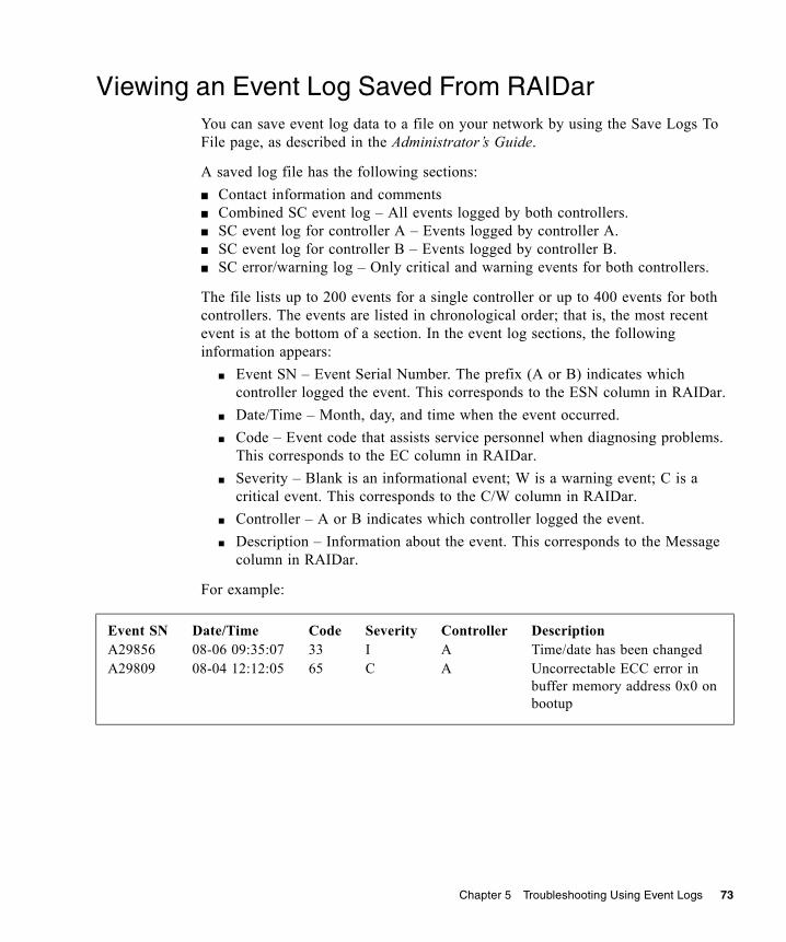
Chapter 5 Troubleshooting Using Event Logs 73
Viewing an Event Log Saved From RAIDarYou can save event log data to a file on your network by using the Save Logs To File page, as described in the Administrator’s Guide.
A saved log file has the following sections:■ Contact information and comments■ Combined SC event log – All events logged by both controllers.■ SC event log for controller A – Events logged by controller A.■ SC event log for controller B – Events logged by controller B.■ SC error/warning log – Only critical and warning events for both controllers.
The file lists up to 200 events for a single controller or up to 400 events for both controllers. The events are listed in chronological order; that is, the most recent event is at the bottom of a section. In the event log sections, the following information appears:
■ Event SN – Event Serial Number. The prefix (A or B) indicates which controller logged the event. This corresponds to the ESN column in RAIDar.
■ Date/Time – Month, day, and time when the event occurred.■ Code – Event code that assists service personnel when diagnosing problems.
This corresponds to the EC column in RAIDar.■ Severity – Blank is an informational event; W is a warning event; C is a
critical event. This corresponds to the C/W column in RAIDar.■ Controller – A or B indicates which controller logged the event.■ Description – Information about the event. This corresponds to the Message
column in RAIDar.
For example:
Event SNA29856A29809
Date/Time08-06 09:35:0708-04 12:12:05
Code3365
SeverityIC
ControllerAA
DescriptionTime/date has been changedUncorrectable ECC error in buffer memory address 0x0 on bootup

74 R/Evolution 5000 Series Troubleshooting Guide • October 2007
Reviewing Event LogsWhen reviewing events, do the following:
1. Review the critical/warning events. Identify the primary events and any that might be the cause of the primary event. For example, an over-temperature event could cause a drive failure.
2. Review the event log for the controller that reported the critical/warning event by viewing the event log by controller. Locate the critical/warning events in the sequence.Repeat this step for the other controller if necessary.
3. Review the events that occurred before and after the primary event.During this review you are looking for any events that might indicate the cause of the critical/warning event. You are also looking for events that resulted from the critical/warning event, known as secondary events.
4. Review the events following the primary and secondary events.You are looking for any actions that might have already been taken to resolve the problems reported by the events.

Chapter 5 Troubleshooting Using Event Logs 75
Configuring the Debug LogWhen instructed to do so by service personnel, as an Advanced Manage user you can configure the debug log. The debug log captures data that will help engineering locate problems within the system logic.
After you configure the debug log as instructed, you will need to perform I/O to the system or recreate the situation that is causing the fault. This populates the debug log with information that engineering can use to diagnose the system.
Note – The debug log only collects data after you configure it. It will not contain information about any problems that occurred before you configure it.
To configure the debug log:
1. Select Manage > Utilities > Debug Utilities > Debug Log Setup. The Debug Log Setup page is displayed.
2. Select the debug log setup you want.■ Standard – Used for diagnosing general problems. With minimal impact on I/O
performance, it collects a wide range of debug data.■ Fibre Channel Performance – Used for diagnosing Fibre Channel problems. This
option dedicates the debug log to collecting Fibre Channel data, with minimal impact on I/O performance.
■ Device-Side – Used for diagnosing device-side problems. This option collects device failure data and Fibre Channel data, with minimal impact on I/O performance.
■ Device Management – Collects very verbose information, including all Configuration API (CAPI) transactions. Because this option collects a lot of data, it has a substantial impact on performance and quickly fills up the debug trace.
■ Custom Debug Tracing – Shows that specific events are selected for inclusion in the log. This is the default. If no events are selected, this option is not displayed.
3. Click Change Debug Logging Setup.
4. If instructed by service personnel, click Advanced Debug Logging Setup Options and select one or more additional types of events.Under normal conditions, none of these options should be selected because they have a slight impact on read/write performance.

76 R/Evolution 5000 Series Troubleshooting Guide • October 2007
Viewing the Debug LogAs a Diagnostic Manage user, you can set debug log display options on the View Debug Log page and then generate and view log entries. The type of data included in the log is configured on the Debug Log Setup page (see “Configuring the Debug Log” on page 75). Each log entry includes a time stamp and a message.
To view the debug log:
1. Select Manage > Utilities > Debug Utilities > View Debug Log.
2. Set the number of lines to display.The default is 400.
3. Select the controller to display debug lines from.The default is controller A.
4. Click Load/Reload Debug Log.The Debug Log Timestamp value is updated to show when the log was generated, and the log data is displayed.

77
CHAPTER 6
Voltage and Temperature Warnings
The storage system provides voltage and temperature warnings, which are generally input or environmental conditions. Voltage warnings can occur if the input voltage is too low or if a FRU is receiving too little or too much power from the power-and-cooling module. Temperature warnings are generally the result of a fan failure, a FRU being removed from an enclosure for a lengthy time period, or a high ambient temperature around an enclosure.
This chapter describes the steps to take to resolve voltage and temperature warnings and provides information about the power supply, cooling fan, temperature, and voltage sensor locations and alarm conditions. Topics covered in this chapter include:■ “Resolving Voltage and Temperature Warnings” on page 77■ “Sensor Locations” on page 78
Resolving Voltage and Temperature WarningsTo resolve voltage and temperature warnings:
1. Check that all of the fans are working by making sure each power-and-cooling module’s DC Voltage/Fan Fault/Service Required LED is off or by using the RAIDar Status Summary page (see “Determining Storage System Status and Verifying Faults” on page 36).
2. Make sure that all modules are fully seated in their slots and that their latches are locked.
3. Make sure that no slots are left open for more than two minutes. If you need to replace a module, leave the old module in place until you have the replacement or use a blank module to fill the slot. Leaving a slot open negatively affects the airflow and can cause the enclosure to overheat.
4. Try replacing each power-and-cooling module one at a time.
5. Replace the controller modules, one at a time.

78 R/Evolution 5000 Series Troubleshooting Guide • October 2007
Sensor LocationsThe storage system monitors conditions at different points within each enclosure to alert you to problems. Power, cooling fan, temperature, and voltage sensors are located at key points in the enclosure. In the SAS expander in each controller module and expansion module, the enclosure management processor (EMP) monitors the status of these sensors to perform SCSI enclosure services (SES) functions. Various RAIDar pages display the sensor information; for example, Monitor > Status > Module Status.
The following sections describe each element and its sensors.
Power Supply Sensors
As shown in Figure 6-1, each enclosure has two fully redundant power-and-cooling modules with load-sharing capabilities. The power supply sensors described in the following table monitor the voltage, temperature, and fans in each power-and-cooling module. If the power supply sensors report a voltage that is under or over the threshold, check the input voltage.
Table 6-1 Power Supply Sensors
Description Location Alarm Conditions
Power supply 0 Power-and-cooling module 0 Voltage, temperature, or fan fault
Power supply 1 Power-and-cooling module 1 Voltage, temperature, or fan fault

Chapter 6 Voltage and Temperature Warnings 79
Figure 6-1 Power-and-Cooling Module and Cooling Fan Locations
Cooling Fan Sensors
As shown in Figure 6-1, each power-and-cooling module includes two fans. The normal range for fan speed is 4000 to 6000 RPM. When a fan’s speed drops below 4000 RPM, the EMP considers it a failure and posts an alarm in the storage system’s event log. The following table lists the description, location, and alarm condition for each fan. If the fan speed remains under the 4000 RPM threshold, the internal enclosure temperature may continue to rise. Replace the power-and-cooling module reporting the fault.
During a shutdown, the cooling fans do not shut off. This allows the enclosure to continue cooling.
Table 6-2 Cooling Fan Sensor Descriptions
Description Location Alarm Condition
Fan 0 Power-and-cooling module 0 < 4000 RPM
Fan 1 Power-and-cooling module 0 < 4000 RPM
Fan 2 Power-and-cooling module 1 < 4000 RPM
Fan 3 Power-and-cooling module 1 < 4000 RPM
Power-and-cooling module 1
Power-and-cooling
Fan 0Fan 1
Fan 3Fan 2
module 0

80 R/Evolution 5000 Series Troubleshooting Guide • October 2007
Temperature Sensors
Extreme high and low temperatures can cause significant damage if they go unnoticed. Each controller module has six temperature sensors. Of these, if the CPU or FPGA temperature reaches a shutdown value, the controller module is automatically shut down. Each power-and-cooling module has one temperature sensor.
When a temperature fault is reported, it must be remedied as quickly as possible to avoid system damage. This can be done by warming or cooling the installation location.
Table 6-3 Controller Module Temperature Sensors
Description
Normal Operating Range
Warning Operating Range
Critical Operating Range
Shutdown Values
CPU Temperature 3–92°C 0–3°C, 92–95°C
> 95°C 0°C 105°C
FPGA Temperature 3–92°C 0–3°C, 92–95°C
0°C95°C
Onboard Temperature 1
Onboard Temperature 2
Capacitor Temperature 0–70°C
CM Temperature
Table 6-4 Power-and-Cooling Module Temperature Sensors
Description
Normal Operating Range
Warning Operating Range
Critical Operating Range
Shutdown Values
Power Supply 1 Temperature(power-and-cooling module 0)
0–80°C
Power Supply 2 Temperature(power-and-cooling module 0)
0–80°C

Chapter 6 Voltage and Temperature Warnings 81
To view the controller enclosure’s temperature status, in RAIDar, as an Advanced Manage user:
● Select Monitor > Status > Advanced Settings > Temperature Status.For more information see RAIDar help or the Administrator’s Guide.
Voltage Sensors
Voltage sensors ensure that an enclosure’s voltage is within normal ranges. For each sensor, the following table lists the description, location, and alarm conditions.
Table 6-5 Voltage Sensor Descriptions
Description Location Alarm Conditions
Voltage sensor 0 Power-and-cooling module 0 (5V) < 4.00V> 6.00V
Voltage sensor 1 Power-and-cooling module 0 (12V) < 11.00V> 13.00V
Voltage sensor 2 Power-and-cooling module 1 (5V) < 4.00V> 6.00V
Voltage sensor 3 Power-and-cooling module 1 (12V) < 11.00V> 13.00V
Voltage sensor 4 Upper controller module (2.5V Local) < 2.25V> 2.75V
Voltage sensor 5 Upper controller module (3.3V Local) < 3.00V> 3.60V
Voltage sensor 6 Upper controller module (midplane 5V) < 4.00V> 6.00V
Voltage sensor 7 Upper controller module (midplane 12V) < 11.00V> 13.00V
Voltage sensor 8 Lower controller module (2.5V Local) < 2.25V> 2.75V
Voltage sensor 9 Lower controller module (3.3V Local) < 3.00V> 3.60V
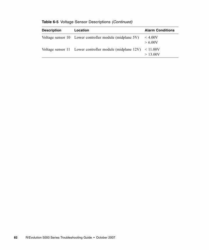
82 R/Evolution 5000 Series Troubleshooting Guide • October 2007
Voltage sensor 10 Lower controller module (midplane 5V) < 4.00V> 6.00V
Voltage sensor 11 Lower controller module (midplane 12V) < 11.00V> 13.00V
Table 6-5 Voltage Sensor Descriptions (Continued)
Description Location Alarm Conditions

83
CHAPTER 7
Troubleshooting and Replacing FRUs
This chapter describes how to troubleshoot and replace field-replaceable units. A field-replaceable unit (FRU) is a system component that is designed to be replaced onsite.
This chapter contains the following sections:■ “Available FRUs” on page 84■ “Static Electricity Precautions” on page 85■ “Identifying Controller or Expansion Module Faults” on page 85■ “Removing and Replacing a Controller or Expansion Module” on page 87■ “Updating Firmware” on page 94■ “Identifying Cable Faults” on page 96■ “Identifying Drive Module Faults” on page 97■ “Removing and Replacing a Drive Module” on page 103■ “Identifying Virtual Disk Faults” on page 110■ “Identifying Power-and-Cooling Module Faults” on page 112■ “Removing and Replacing a Power-and-Cooling Module” on page 113■ “Replacing an Enclosure” on page 115
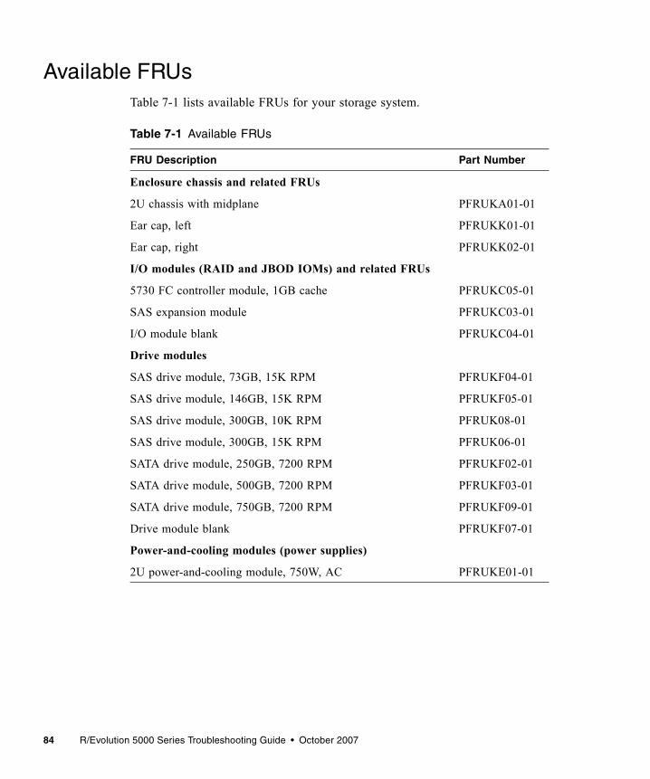
84 R/Evolution 5000 Series Troubleshooting Guide • October 2007
Available FRUsTable 7-1 lists available FRUs for your storage system.
Table 7-1 Available FRUs
FRU Description Part Number
Enclosure chassis and related FRUs
2U chassis with midplane PFRUKA01-01
Ear cap, left PFRUKK01-01
Ear cap, right PFRUKK02-01
I/O modules (RAID and JBOD IOMs) and related FRUs
5730 FC controller module, 1GB cache PFRUKC05-01
SAS expansion module PFRUKC03-01
I/O module blank PFRUKC04-01
Drive modules
SAS drive module, 73GB, 15K RPM PFRUKF04-01
SAS drive module, 146GB, 15K RPM PFRUKF05-01
SAS drive module, 300GB, 10K RPM PFRUK08-01
SAS drive module, 300GB, 15K RPM PFRUK06-01
SATA drive module, 250GB, 7200 RPM PFRUKF02-01
SATA drive module, 500GB, 7200 RPM PFRUKF03-01
SATA drive module, 750GB, 7200 RPM PFRUKF09-01
Drive module blank PFRUKF07-01
Power-and-cooling modules (power supplies)
2U power-and-cooling module, 750W, AC PFRUKE01-01

Chapter 7 Troubleshooting and Replacing FRUs 85
Static Electricity PrecautionsTo prevent damaging a FRU, make sure you follow these static electricity precautions:■ Remove plastic, vinyl, and foam from the work area.■ Wear an antistatic wrist strap, attached to a ground.■ Before handling a FRU, discharge any static electricity by touching a ground
surface.■ Do not remove a FRU from its antistatic protective bag until you are ready to
install it.■ When removing a FRU from a controller enclosure, immediately place the FRU
in an antistatic bag and in antistatic packaging.■ Handle a FRU only by its edges and avoid touching the circuitry.■ Do not slide a FRU over any surface.■ Limit body movement (which builds up static electricity) during FRU
installation.
Identifying Controller or Expansion Module FaultsThe controller and expansion modules contain subcomponents that require the replacement of the entire FRU should they fail. Each controller and expansion module contains LEDs that can be used to identify a fault. Additionally, you can use RAIDar to locate and isolate controller and expansion module faults. See “Troubleshooting Using RAIDar” on page 35.
Note – When troubleshooting, ensure that you review the reported events carefully. The controller module is often the FRU reporting faults, but is not always the FRU where the fault is occurring.

86 R/Evolution 5000 Series Troubleshooting Guide • October 2007
Table 7-2 lists the faults you might encounter with a controller module or expansion module.
Table 7-2 Controller Module or Expansion Module Faults
Problem Solution
FRU OK LED is off • Verify that the controller module is properly seated in the slot and latched.
• Check the RAIDar event log for power-on initialization events and diagnostic errors.
FRU Fault LED is on • Examine the event log to determine if there is any error event and take appropriate action.
• Call technical support and send in the log and event files.• Replace the controller that displayed the fault LED.
Only one controller module boots
• In a dual-controller module configuration, if a conflict between controllers exists, only controller module A will boot. For example, if the cache size is different on the controller modules, controller module B will not boot.
An SDRAM memory error is reported
• Replace the controller module where the error occurred.
Controller FailureEvent codes 84 and 74
• The controller might need to have its firmware upgraded or be replaced.
• Check the specific error code to determine the corrective action to take.
Controller voltage fault • Check the power-and-cooling module and the input voltage.
Controller temperature fault • Check that the enclosure fans are running.• Check that the ambient temperature is not too warm. See the
System Site Planning Guide for temperature specifications.• Check for any obstructions to the airflow.When the problem is fixed, event 47 is logged.
Memory ErrorEvent code 65 and 138
• Contact Technical Support.• The controller module needs to be replaced.Event 72 indicates that, after the failover to the other controller, the recovery has started.
Flash write failureEvent code 157
• The controller needs to be replaced.
Firmware mismatchEvent code 89
• The downlevel controller needs to be upgraded.

Chapter 7 Troubleshooting and Replacing FRUs 87
Removing and Replacing a Controller or Expansion Module
In a dual-controller configuration, controller and expansion modules are hot-swappable, which means you can replace one module without halting I/O to the storage system or powering it off. In this case, the second module takes over operation of the storage system until you install the new module.
In a single-controller configuration, I/O to the storage system must be halted and the storage system must be powered off.
A controller or expansion module might need replacing when:■ The Fault/Service Required LED is illuminated■ Events in RAIDar indicate a problem with the module■ Troubleshooting indicates a problem with the module■ The internal clock battery fails
Caution – In a dual-controller configuration, both controllers must have the same cache size. If the new controller has a different cache size, controller A will boot and controller B will not boot. To view the cache size, select Monitor > Advanced Settings > Controller Versions.
Saving Configuration Settings
Before replacing a controller module, save the storage system’s configuration settings to file. This enables you to make a backup of your settings in case a subsequent configuration change causes a problem, or if you want to apply one system’s settings to another system.
The file contains all system configuration data, including: ■ LAN configuration settings■ Host port configuration settings■ Enclosure management settings■ Disk configuration settings■ Services security settings■ System information settings■ System preference settings■ Event notification settings

88 R/Evolution 5000 Series Troubleshooting Guide • October 2007
The configuration file does not include configuration data for virtual disks and volumes. You do not need to save this data before replacing a controller or expansion module because the data is saved as metadata in the first sectors of associated member disk drives.
To save system configuration data to a file on the management host or network:
1. In RAIDar, connect to the IP address of one of the controller modules.
2. Select Manage > Utilities > Configuration Utilities > Save Config File.
3. Click Save Configuration File.
4. If prompted to open or save the file, click Save.
5. If prompted to specify the file location and name, do so using a .config extension. The default file name is saved_config.config.
Note – If you are using Firefox and have a download directory set, the file is automatically saved there.

Chapter 7 Troubleshooting and Replacing FRUs 89
Shutting Down a Controller Module
Shut down a controller module before you remove it from an enclosure, or before you power off its enclosure for maintenance, repair, or a move. Shutting down a controller module halts I/O to that module, ensures that any data in the write cache is written to disk, and initiates failover to the partner controller, if it is active.
Caution – If both controllers are shut down, you have limited management capability for the storage system and host applications do not have access to its volumes. If you want the system to remain available, before shutting down one controller verify that the other controller is active.
To shut down a controller module:
1. Select Manage > Restart System > Shut Down/Restart.
2. In the Shut Down panel, select a controller option.
3. Click Shut Down.A warning might appear that data access redundancy will be lost until the selected controller is restarted. This is an informational message that requires no action.
4. Confirm the operation by clicking OK.

90 R/Evolution 5000 Series Troubleshooting Guide • October 2007
Removing a Controller Module or Expansion Module
As long as the other module in the enclosure you are removing remains online and active, you can remove a module without powering down the enclosure; however you must shut down a controller module as described in “Shutting Down a Controller Module” on page 89.
Caution – When you remove a module with the enclosure powered on, within two minutes install a replacement module or a blank; otherwise, the enclosure might overheat.
To remove a controller module or expansion module:
1. Follow all static electricity precautions as described in “Static Electricity Precautions” on page 85.
2. Use RAIDar to check the status of the partner module.To ensure continuous availability of the system, be sure that the partner module is online. If the partner is offline, resolve the problem with that module before continuing this procedure.
3. If you are removing a controller module and the partner module is online, use RAIDar to shut down the module that you want to remove; see “Shutting Down a Controller Module” on page 89.You need to use the Shut Down function for controller modules only. The blue OK to Remove LED illuminates to indicate that the module can be removed safely.
4. Use RAIDar to blink the Unit Locator LED of the enclosure that contains the module to remove:
a. Select Manage > General Config > Enclosure Management.
b. Click Illuminate Locator LED.
5. Physically locate the enclosure whose Unit Locator LED is blinking and within it, the module whose OK to Remove LED is blue.
6. If the controller module is connected with SAS cables to an expansion enclosure, disconnect those SAS cables.

Chapter 7 Troubleshooting and Replacing FRUs 91
7. Turn the thumbscrew on each latch (see Figure 7-1) counterclockwise until the screw disengages from the module. Do not remove the screw from the handle.
Figure 7-1 Location of Thumbscrews on I/O Module Latches (5730 Shown)
8. Press both latches downward to disconnect the module from the midplane.
9. Pull outward on the latches to slide the module out of the enclosure.
Installing a Controller Module or Expansion Module
You can install a controller module or expansion module into an enclosure that is powered on.
Caution – When replacing a controller module, ensure that less than 10 seconds elapse between inserting the module into a slot and fully latching it in place. Failing to do so might cause the controller to fail. If it is not latched within 10 seconds, remove the module from the slot and repeat the process.
To install a controller module or an expansion module:
1. Follow all static electricity precautions as described in “Static Electricity Precautions” on page 85.
2. Loosen the thumbscrews on the latches of the new module and press the latches downward.
3. Orient the module with the latches toward the top and slide the module into a slot as far as it will go.
10/100 BASE-T STATUS STATUSACTIVITY
DIRTYCLEAN
CACHECLI
Service
LatchThumbscrewThumbscrewLatch
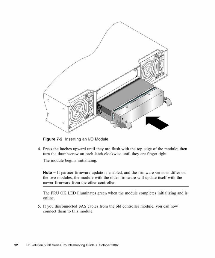
92 R/Evolution 5000 Series Troubleshooting Guide • October 2007
Figure 7-2 Inserting an I/O Module
4. Press the latches upward until they are flush with the top edge of the module; then turn the thumbscrew on each latch clockwise until they are finger-tight.The module begins initializing.
Note – If partner firmware update is enabled, and the firmware versions differ on the two modules, the module with the older firmware will update itself with the newer firmware from the other controller.
The FRU OK LED illuminates green when the module completes initializing and is online.
5. If you disconnected SAS cables from the old controller module, you can now connect them to this module.

Chapter 7 Troubleshooting and Replacing FRUs 93
6. If the enclosure’s Unit Locator LED is blinking, use RAIDar to stop it:
a. Select Manage > General Config > Enclosure Management.
b. Click Turn Off Locator LED.
Fault/Service RequiredIf the Fault/Service Required yellow LED is illuminated, the module has not gone online and likely failed its self-test. Try to put the module online (see “Shutting Down a Controller Module” on page 89) or check for errors that were generated in the event log from RAIDar.
Boot Handshake Error
When powering on the controllers, if RAIDar or the event log report a boot handshake error, power off the enclosure for two seconds and then power it on again. If this does not correct the error, remove and replace each controller as described in “Removing a Controller Module or Expansion Module” on page 90.
Setting the Internal Clock
If the battery on the internal clock fails, and power from both power modules fail, the internal clock is reset to January 1, 1976. The clock battery is not a FRU. You must send in the controller module for service to have the battery replaced.
When the serviced controller module is reinserted into the enclosure, the controller’s date and time are automatically updated to match the date and time of the partner controller.
In a single controller configuration, you must set the clock manually. To set the date and time in RAIDar, select Manage > General Config > Set Date/Time.
Persistent IP Address
The IP address for each controller is stored in a SEEPROM on the midplane. The IP address is persistent. When you replace a controller, the new controller will have the same IP address as the old controller.

94 R/Evolution 5000 Series Troubleshooting Guide • October 2007
Moving a Set of Expansion Modules
The enclosure ID for the RAID controller is always zero. The expansion modules are then numbered from one to four. The number is visible on the front on the enclosure. If you move a single expansion module, or a set of expansion modules to another controller and reconnect them in a different order, an error will occur. The enclosure ID is not updated. Always move a complete set of expansion modules and connect them in the same order as they were connected to the original controller module.
Updating FirmwareOccasionally new firmware is released to provide new features and fixes to known issues. The firmware is updated during controller replacement or by using RAIDar.
Caution – Do not power off the storage system during a firmware upgrade. Doing so might cause irreparable damage to the controllers.
Updating Firmware During Controller Replacement
When a replacement controller is sent from the factory, it might have a more recent version of firmware installed than the surviving controller in your system. By default, when you insert the replacement controller, the system compares the firmware of the existing controller and that of the new controller. The controller with the oldest firmware automatically downloads the firmware from the controller with the most recent firmware (partner firmware upgrade). If told to do so by a service technician, you can disable the partner firmware upgrade function using RAIDar.
Disabling Partner Firmware Upgrade
The partner firmware upgrade option is enabled by default in RAIDar. Only disable this function if told to do so by a service technician.
1. Select Manage > General Config > System Configuration.
2. For Partner Firmware Upgrade, select Disable.
Chapter 7 Troubleshooting and Replacing FRUs 95
Updating Firmware Using RAIDar
RAIDar enables you to upgrade the firmware in your storage system when new releases are available.
Note – The controllers share one memory buffer for gathering log data and for loading firmware. Do not try to perform more than one firmware-update operation at a time, or to perform a firmware-update operation while performing a save-logs operation. Doing so will display a “buffer busy” error.
To update your firmware using RAIDar, perform the following steps:
1. Refer to the Release Notes for your system for any late-breaking information related to updating the firmware.
2. Ensure that the software package file is saved to a location on your network that the storage system can access.
3. Select Manage > Update Software > Controller Software.The Load Software panel is displayed, which describes the update process and lists your current software versions.
4. Click Browse and select the software package file.
5. Click Load Software Package File. If the storage system finds a problem with the file, it shows a message at the top of the page. To resolve the problem, try the following:■ Be sure to select the software package file that you just downloaded.■ Download the file again, in case it got corrupted. Do not attempt to edit the file.After about 30 seconds, the Load Software to Controller Module panel is displayed. This page lets you know whether the file was validated and what software components are in the file. The storage system only updates the software that has changes.
6. Review the current and new software versions, and then click Proceed with Code Update.A Code Load Progress window is displayed to show the progress of the update, which can take several minutes to complete. Do not power off the storage system during the code load process. Once the firmware upload is complete, the controller resets, after which the opposite controller automatically repeats the process to load

96 R/Evolution 5000 Series Troubleshooting Guide • October 2007
the new firmware. When the update completes on the connected controller, you are logged out. Wait one minute for the controller to start and click Log In to reconnect to RAIDar.
Identifying Cable FaultsWhen identifying cable faults you must remember that there are two sides of the controller: the input/output to the host and the input/output to the expansion enclosures. It is also important to remember that identifying a cable fault can be difficult due to the multiple components that make up the data paths that cannot be overlooked as a cause of the fault.
Before you take to many troubleshooting steps, ensure you have reviewed the proper cabling steps in the Getting Started Guide and Best Practices Guide. Many faults can be eliminated by properly cabling the storage system.
Identifying Cable Faults on the Host Side
To identify a faulty cable on the host side, use the host link status LED and perform the troubleshooting procedure described in “Using Controller Module Host Port LEDs” on page 29.
Identifying Cable Faults on the Expansion Enclosure Side
To identify a cable fault on the expansion enclosure side, perform the troubleshooting procedure described in “Using Expansion Module LEDs” on page 33.

Chapter 7 Troubleshooting and Replacing FRUs 97
Disconnecting and Reconnecting SAS Cables
The storage system supports disconnecting and reconnecting SAS cables between enclosures while the system is active. You might need to do this as part of replacing an I/O module.
The guidelines are as follows:■ If less than 15 seconds elapses between disconnecting and reconnecting a cable
to the same port, no further action is required.■ If less than 15 seconds elapses between disconnecting a cable and connecting it
to a different port in the same enclosure or in a different enclosure, you must perform a manual rescan. In RAIDar, select Manage > Utilities > Disk Drive Utilities > Rescan.
■ If at least 15 seconds elapses between disconnecting a cable and connecting it to a different port in the same enclosure or in a different enclosure, no further action is required.
Identifying Drive Module FaultsWhen identifying faults in drive modules you must:■ Understand disk-related errors■ Be able to determine if the error is due to a faulty disk drive or faulty disk drive
channel■ Identify what action the controller has taken to protect the virtual disk after the
drive fault occurred (that is, rebuilding to a hot spare)■ Know how to identify disk drives in the enclosure■ Understand the proper procedure for replacing a faulty drive module

98 R/Evolution 5000 Series Troubleshooting Guide • October 2007
Understanding Disk-Related Errors
The event log includes errors reported by the enclosure management processors (EMPs) and disk drives in your storage system. If you see these errors in the event log, the following information will help you understand the errors.
When a disk detects an error, it reports it to the controller by returning a SCSI sense key and, if appropriate, additional information. This information is recorded in the RAIDar event log. Table 7-3 lists some of the most common SCSI sense key descriptions (in hexadecimal). Table 7-4 lists the descriptions for the standard SCSI sense codes (ASC) and sense code qualifiers (ASCQ), all in hexadecimal. See the SCSI Primary Commands - 2 (SPC-2) Specification for a complete list of ASC and ASCQ descriptions.
Table 7-3 Standard SCSI Sense Key Descriptions
Sense Key Description
0h No sense
1h Recovered error
2h Not ready
3h Medium error
4h Hardware error
5h Illegal request
6h Unit attention
7h Data protect
8h Blank check
9h Vendor-specific
Ah Copy aborted
Bh Aborted command
Ch Obsolete
Dh Volume overflow
Eh Miscompare
Fh Reserved

Chapter 7 Troubleshooting and Replacing FRUs 99
Disk Drive Errors
In general, media errors (sense key 3), recovery errors (sense key 1), and SMART events (identified by the following text in the event logs: “SMART event”) clearly point to a problem with a specific drive. Other events, such as protocol errors and I/O timeouts, might suggest drive problems, but also might be indicative of poorly seated or faulty cables, problems with particular drive slots, or even problems with the drive’s dongle, a small printed circuit board attached to the drive carrier of each drive. Each of these events may result in a warning or critical notification in RAIDar and the event log.
Table 7-4 Common ASC and ASCQ Descriptions
ASC ASCQ Descriptions
0C 02 Write error – auto-reallocation failed
0C 03 Write error – recommend reassignment
11 00 Unrecovered read error
11 01 Read retries exhausted
11 02 Error too long to correct
11 03 Multiple read errors
11 04 Unrecovered read error – auto-reallocation failed
11 0B Unrecovered read error – recommend reassignment
11 0C Unrecovered read error – recommend rewrite the data
47 01h Data phase CRC error detected

100 R/Evolution 5000 Series Troubleshooting Guide • October 2007
Disk Channel Errors
Disk channel errors are similar to disk-detected errors, except they are detected by the controllers instead of the disk drive. Some disk channel errors are displayed as text strings. Others are displayed as hexadecimal codes.
If the error is a critical error, perform the steps in “Disk Drive Errors” on page 99.
Table 7-5 lists the descriptions for disk channel errors. Most disk channel errors are informational because the storage system issues retries to correct any problem. Errors that cannot be corrected with retries result in another critical event describing the affected array (if any).
Table 7-5 Disk Channel Error Codes
Error Code Description
CRC Error CRC error on data was received from a target.
Dev Busy Target reported busy status.
Dn/Ov Run Data overrun or underrun has been detected.
IOTimeout Array aborted an I/O request to this target because it timed out.
Link Down Link down while communication in progress.
LIP I/O request was aborted because of a channel reset.
No Respon No response from target.
Port Fail Disk channel hardware failure. This may be the result of bad cabling.
PrtcolError Array detected an unrecoverable protocol error on the part of the target.
QueueFull Target reported queue full status.
Stat: 04 Data overrun or underrun occurred while getting sense data.
Stat: 05 Request for sense data failed.
Stat: 32 Target has been reserved by another initiator.
Stat: 42 I/O request was aborted because of array’s decision to reset the channel.
Stat: 44 Array decided to abort I/O request for reasons other than bus or target reset.
Stat: 45 I/O request was aborted because of target reset requested by array.
Stat: 46 Target did not respond properly to abort sequence.

Chapter 7 Troubleshooting and Replacing FRUs 101
Identifying Faulty Drive Modules
To identify faulty drive modules, perform the following steps:
1. Does the fault involve a single drive?■ If yes, perform steps Step 2 through Step 4.■ If an entire enclosure of disk drives are faulty, check your cabling and, if
necessary, perform the steps in “Identifying Cable Faults” on page 96.
2. Identify the suspected faulty disk drive using the LEDs.
3. Replace the suspected faulty disk drive with a known good drive (a replacement drive).
4. Does this correct the fault?■ If yes, the fault has been corrected and no further action is necessary.■ If no, continue to Step 5.
5. The fault may be caused by a bad disk drive slot on the midplane. Confirm your findings by powering off the storage system, moving an operating disk drive into the suspected slot, and re-applying power.
Note – Step 5 requires that you schedule downtime for the system.
6. Does this drive fail when placed in the suspected slot?■ Yes, replace the enclosure. You have located the faulty FRU.■ No, continue to Step 7.
7. If the drive does not fail, move it back to it original slot and ensure the replacement drive is fully inserted into the slot.If the drive fails again the midplane may have an intermittent fault or the connector is dirty, replace the enclosure.
102 R/Evolution 5000 Series Troubleshooting Guide • October 2007
Updating Disk Drive Firmware
Note – To update a disk drive’s firmware, the disk cannot be part of a virtual disk. The update procedure might work; however, the disk drive manufactures will not guarantee the integrity of the data on the disk.
If the disk drives do not have the latest firmware, update the firmware. You can determine the firmware revision level by selecting Manage > Update Software > Disk Drive Firmware >Show Disk Drive Types.
1. Backup all data on the virtual disk.
2. Remove the disk from the virtual disk. You can also delete the virtual disk and recreate it after the upgrade procedure if all the disks need to have their firmware updated. To see what virtual disk the disk drive in a part of, selectMonitor > Status > Enclosure View and move the mouse over the disk drives.
3. For the Maxtor disk drives only, shut down controller module B. For updating other manufacturers disk drives, you do not need to shut down controller module B.
Caution – The Maxtor disk drive firmware can incorrectly load if both controllers are running. This will result in the loss of the firmware and require the replacement of the disk drives.
4. Select Manage > Update Software > Disk Drive Firmware > Update Firmware.
5. Select the type of disk drives to be updated.
6. Select the specific disk drives to be updated. If you select a drive that is part of a virtual disk, a warning message is displayed.
7. Select the location where the disk drive firmware is located and click Load Device Firmware.Disk drive firmware is available from the disk drive manufacturer, or your storage system vendor.For the Maxtor disk drives, update to firmware revision BK00 or later.

Chapter 7 Troubleshooting and Replacing FRUs 103
8. For the Maxtor disk drives, restart controller B.
9. Verify that the disk drives are at the new firmware revisions level by selecting Manage > Update Software > Disk Drive Firmware > Show Disk Drive Types.
Removing and Replacing a Drive ModuleA drive module consists of a disk drive in a sled. Drive modules are hot-swappable, which means they can be replaced without halting I/O to the storage system or powering it off.
Caution – To prevent any possibility of data loss, back up data to another virtual disk or other location before removing the drive module.
Caution – When you replace a drive module, the new module must be the same type (SAS or SATA) and must have a capacity equal to or greater than the drive module you are replacing. Otherwise the storage system will not accept the new disk drive for the virtual disk.
If you are using disk management software or volume management software to manage your disk storage, you might need to perform software operations to take a drive module offline before you remove it and then, after you have replaced it, to bring the new drive module online. See the documentation that accompanies your disk management software or volume management software for more information.

104 R/Evolution 5000 Series Troubleshooting Guide • October 2007
Replacing a Drive Module When the Virtual Disk Is Rebuilding
When a drive module fails or is removed, the system rebuilds the virtual disk by restoring any data that was on the failed disk drive onto a global spare or virtual disk spare, if one is available. If you replace more than one drive module at a time, the virtual disk cannot be rebuilt. If more than one drive module fails in a virtual disk (except RAID 6 and 10), the virtual disk fails and data from the virtual disk is lost.
When you want to replace a drive module and a virtual disk to which it belongs is being rebuilt, you have two options:■ Wait until the rebuild process is completed, and then replace the defective drive
module. The benefit is that the virtual disk is fully restored before you replace the defective drive. This eliminates the possibility of lost data if the wrong drive is removed.
■ Replace the defective drive and make the new drive a global spare while the rebuilding process continues. This procedure installs the new drive and assigns it as a global spare so that an automatic rebuild can occur if a drive module fails on another virtual disk. If a drive module fails in another virtual disk before a new global spare is assigned, you must manually rebuild the virtual disk.
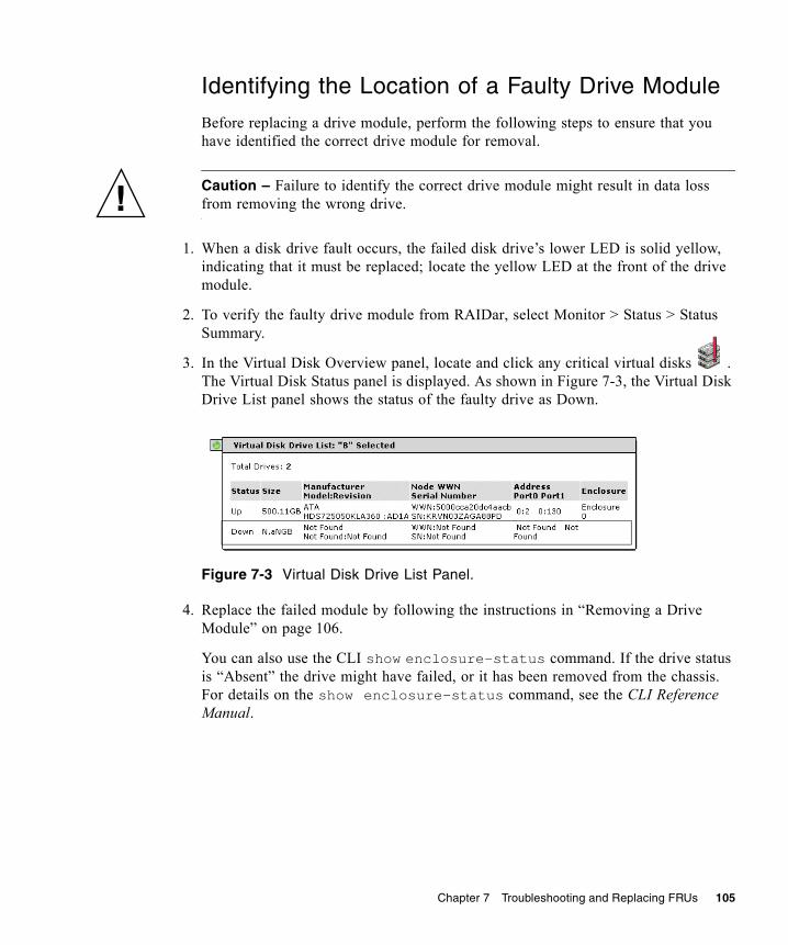
Chapter 7 Troubleshooting and Replacing FRUs 105
Identifying the Location of a Faulty Drive Module
Before replacing a drive module, perform the following steps to ensure that you have identified the correct drive module for removal.
Caution – Failure to identify the correct drive module might result in data loss from removing the wrong drive.
1. When a disk drive fault occurs, the failed disk drive’s lower LED is solid yellow, indicating that it must be replaced; locate the yellow LED at the front of the drive module.
2. To verify the faulty drive module from RAIDar, select Monitor > Status > Status Summary.
3. In the Virtual Disk Overview panel, locate and click any critical virtual disks . The Virtual Disk Status panel is displayed. As shown in Figure 7-3, the Virtual Disk Drive List panel shows the status of the faulty drive as Down.
Figure 7-3 Virtual Disk Drive List Panel.
4. Replace the failed module by following the instructions in “Removing a Drive Module” on page 106.
You can also use the CLI show enclosure-status command. If the drive status is “Absent” the drive might have failed, or it has been removed from the chassis. For details on the show enclosure-status command, see the CLI Reference Manual.

106 R/Evolution 5000 Series Troubleshooting Guide • October 2007
Removing a Drive Module
When you remove a drive module, it is important to maintain optimum airflow through the chassis by either replacing it immediately with another one or by using an air management module. If you do not have a replacement module or an air management module, do not remove the drive module, that is, it is not harmful to the storage system to keep a fault drive inserted until you have a replacement drive. If you do have an air management module, it is installed using the same procedure for removing a drive module as described below.
Caution – If you remove a drive module and do not replace it within two minutes, you alter the air flow inside the enclosure, which could cause overheating of the enclosure. Do not remove a drive module unless you have a replacement drive module or air management module to immediately replace the one you removed.
To remove a drive from an enclosure, perform the following steps:
1. Follow all static electricity precautions as described in “Static Electricity Precautions” on page 85.
2. Squeeze the release on the left edge of the drive ejector handle (see Figure 7-4).
3. Rotate the handle toward the right to disengage the drive module from the enclosure’s internal connector.
Figure 7-4 Releasing the Drive Module Handle
Squeeze
Drive ejector handle

Chapter 7 Troubleshooting and Replacing FRUs 107
4. Wait 20 seconds for the internal disks to stop spinning.
5. Pull the drive module out of the enclosure.
Installing a Drive Module
To install the a drive module, perform the following steps:
1. Follow all static electricity precautions as described in “Static Electricity Precautions” on page 85.
2. If the ejector handle is closed, squeeze the release on the left edge of the drive ejector handle and rotate the handle toward the right to open the locking mechanism (see Figure 7-4).
3. Orient the drive module with the LEDs to the left. Slide the drive module into the drive slot as far as it will go.
4. Rotate the drive ejector handle toward the left until the release clicks closed to firmly seat the drive module in the enclosure’s internal connector. If the controller enclosure is powered on, the green Power/Activity/Fault LED illuminates, indicating that the disk drive is functional.
5. Use the RAIDar status page (Manage > Vdisk Configuration > Disk Drive Status) to check the status of the disk and then use Table 7-6 to determine how to continue.
Table 7-6 Disk Drive Status
Status Action
The status of the virtual disk that originally had the failed drive status is Good. A global or virtual disk (dedicated) spare has been successfully integrated into the virtual disk and the replacement drive module can be assigned as either a global spare or a virtual disk spare.
Use RAIDar to assign the new drive module as either a global spare or a vdisk spare: Select Manage > Virtual Disk Config > Global Spare Menu.

108 R/Evolution 5000 Series Troubleshooting Guide • October 2007
The status of the disk drive just installed is LEFTOVER.
All of the member disk drives in a virtual disk contain metadata in the first sectors. The storage system uses the metadata to identify virtual disk members after restarting or replacing enclosures.Use RAIDar to clear the metadata if you have a disk drive that was previously a member of a virtual disk. After you clear the metadata, you can use the disk drive in a virtual disk or as a spare:Select Manage > Utilities > Disk Drive Utilities > Clear Metadata.Select the disk, and click on Clear Metadata for Selected Disk Drives.
If the status of the virtual disk that originally had the failed drive status is FATAL FAIL, two or more drive modules have failed.
All data in the virtual disk is lost. Use the RAIDar Trust Virtual Disk function to attempt to bring the virtual disk back online.Select Manage > Utilities > Recovery Utilities > Trust Virtual Disk.Note: You must be a Diagnostic Manage user to access the Trust Virtual Disk submenu. See the Administrator’s Guide for more information on access privileges.
The status of the virtual disk that originally had the failed drive status is DRV ABSENT or INCOMPLETE. These status indicators only occur when the enclosure is initially powered up. DRV ABSENT indicates that one drive module is bad. INCOMPLETE indicates that two or more drive modules are bad.
See “Verify That the Correct Power-On Sequence Was Performed” on page 109. If the power-on sequence was correct, locate and replace the additional failed drive modules.
The status of the virtual disk that originally had the failed drive indicates that the virtual disk is being rebuilt.
Wait for the virtual disk to complete its operation.
The status of the virtual disk that originally had the failed drive is DRV FAILED.
If this status occurs after you replace a defective drive module with a known good drive module, the enclosure midplane might have experienced a failure. Replace the enclosure.
Table 7-6 Disk Drive Status (Continued)
Status Action

Chapter 7 Troubleshooting and Replacing FRUs 109
6. After replacing a failed drive, save the configuration settings as described in “Saving Configuration Settings” on page 87. The saved configuration includes configuration information for all the drive modules in the virtual disk. When you save the configuration settings to a file, you also save the configuration of the virtual disk onto each of the hard drives. This step saves the current configuration onto the new hard drive. If the drive is used as a spare, its metadata is automatically updatd.
Verify That the Correct Power-On Sequence Was Performed
Review the power-on sequence that you most recently used for the enclosure. If you are uncertain about the sequence used, repeat the power-on sequence in the following order to see if it results in a Good status for the virtual disk that originally had the failed drive.
1. Power up the enclosures and associated data host in the following order:
a. Expansion enclosures first
b. Controller enclosure next
c. Data hosts last (if they had been powered down for maintenance purposes)
2. In RAIDar, select Monitor > Status > Vdisk Status to display the virtual disk overview panel. This panel displays an icon for each virtual disk with information about the virtual disk below it.
Installing an Air Management Module
An air management module looks like a drive module; however, it is an empty box used to maintain optimum airflow and proper cooling in an enclosure. If your system was ordered with less than 12 drive modules it was shipped with air management modules for the slots without drive modules. Optionally, air management modules can be ordered.
If you must remove a drive module and cannot immediately replace it, you must leave the faulty drive module in place, or insert an air management module to maintain the optimum airflow inside the chassis. The blank is installed using the same procedure as “Installing a Drive Module” on page 107.

110 R/Evolution 5000 Series Troubleshooting Guide • October 2007
Identifying Virtual Disk FaultsObvious virtual disk problems involve the failure of a member disk drive. However, there are a number of not so obvious issues that result in virtual disk faults as seen in Table 7-7.
Table 7-7 Virtual Disk Faults
Problem Solution
Expanding virtual disk requires days to complete.
• In general, expanding a virtual disk can take days to complete. You cannot stop the expansion once it is started.
• If you have an immediate need, create a new virtual disk of the size you want, transfer your data to the new virtual disk, and delete the old virtual disk.
Failover causes a virtual disk to become critical when one of its drives “disappears.”
• In general, controller failover is not supported if a disk drive is in an expansion enclosure that is connected with only one cable to the controller enclosure. This is because access to the expansion enclosure will be lost if the controller to which it is connected fails. When the controller with the direct connection to the expansion enclosure comes back online, access to the expansion enclosure drives is restored. To avoid this problem, ensure that two cables are used to connect the enclosures as shown in the Getting Started Guide, and that the cables are connected securely and are not damaged.
• If the problem persists or affects a disk drive in a controller enclosure, a hardware problem might have occurred in the drive module, dongle, midplane, or controller module. Identify and replace the FRU where the problem occurred
A virtual disk is much smaller than it should be.
Verify that the disk drives are all the same size within the virtual disk. The virtual disk is limited by the smallest sized disk.
Volumes in the virtual disk are not visible to the host.
Verify that the volumes are mapped to the host using RAIDar:Manage > Volume Management > Volume Mapping > Map by Volume.
Virtual Disk DegradedEvent codes 58 and 1, or event codes 8 and 1
• Replace the failed disk drive and add the replaced drive as a spare to the critical virtual disk.
• If you have dynamic spares enabled, you only need to replace the drive. The system will automatically reconstruct the virtual disk.

Chapter 7 Troubleshooting and Replacing FRUs 111
Clearing Metadata From a Disk Drive
All of the member disk drives in a virtual disk contain metadata in the first sectors. The storage system uses the metadata to identify virtual disk members after restarting or replacing enclosures.
Clear the metadata if you have a disk drive that was previously a member of a virtual disk. Disk drives in this state display “Leftover” in the Display All Devices page and in the Clear Metadata page. After you clear the metadata, you can use the disk drive in a virtual disk or as a spare.
To clear metadata from a disk drive, see “Clearing Metadata From Leftover Disk Drives” on page 51.
Virtual Disk FailureEvent codes 58 and 3, or event codes 8 and 3
Replace the bad disk drive and restore the data from backup.
Virtual Disk QuarantinedEvent code 172
Ensure that all drives are turned on. When the vdisk is de-quarantined, event code 79 is returned.
Spare Disk FailureEvent code 62
• Replace the disk.
• If this disk was a dedicated spare for a vdisk, assign another spare to the vdisk.
Spare Disk UnusableEvent code 78
• The disk might not have a great enough capacity for the vdisk.
• Replace the spare with a disk that has a capacity equal to or greater than the smallest disk in the vdisk.
Mixed drive type errors • Virtual disks do not support mixed drive types.
• Verify that the drives in the virtual disk are of the same type (SATA or SAS) and that they have the same capacity. If you attempt to build a virtual disk with mixed drive types you will receive an error.
• If you attempt to build a virtual disk with various sized disk drives, a warning will be displayed. The capacity of the smallest disk will be set for all others.
Table 7-7 Virtual Disk Faults (Continued)
Problem Solution

112 R/Evolution 5000 Series Troubleshooting Guide • October 2007
Identifying Power-and-Cooling Module FaultsWhen isolating faults in the power-and-cooling module, it is important to remember that the module consists of two primary components: fans and a power supply. When ether of these components fails, RAIDar provides notification, the faults are recorded in the event log, and the power-and-cooling module’s status LED changes from green to yellow. Alternatively, you can use the CLI to poll for events; see the CLI Reference Manual.
Note – When a power supply fails, the fans of the module continue to operate because they draw power from the power bus located on the midplane.
Once a fault is identified in the power-and-cooling module, you need to replace the entire module.
Caution – Because removing the power-and-cooling module significantly disrupts the enclosure’s airflow, do not remove the power-and-cooling module until you have the replacement module.
Table 7-8 lists possible power-and-cooling module faults.
Table 7-8 Power-and-Cooling Module Faults
Fault Solution
Power supply fan warning or failure, orpower supply warning or failure. Event code 168
• Check that all of the fans are working using RAIDar.
• Make sure that no slots are left open for more than 2 minutes. If you need to replace a module, leave the old module in place until you have the replacement, or use a blank cover to close the slot. Leaving a slot open negatively affects the airflow and might cause the unit to overhead.
• Make sure that the controller modules are properly seated in their slots and that their latches are locked.

Chapter 7 Troubleshooting and Replacing FRUs 113
Removing and Replacing a Power-and-Cooling Module
A single power-and-cooling module is sufficient to maintain operation of the enclosure. It is not necessary to halt operations and completely power off the enclosure when replacing only one power-and-cooling module.
Krypton If you power off both power supplies, the internal clock will be reset to January 1, 1970. Use RAIDar to reset the clock. Select: Manage > General Config > Set Date/Time.
Caution – When you remove a power-and-cooling module, install the new module within two minutes of removing the old module. The enclosure might overheat if you take more than two minutes to replace the power-and-cooling module.
Removing a Power-and-Cooling Module
To remove a power-and-cooling module from an enclosure, perform the following steps:
1. Follow all static electricity precautions as described in “Static Electricity Precautions” on page 85.
2. Set the power switch on the module to the Off position.
3. Disconnect the power cable.
Power-and-cooling module status is listed as failed or you receive a voltage event notification. Event code 168
• Check that the switch on each power-and-cooling module is turned on.
• Check that the power cables are firmly plugged into both power-and-cooling modules and into an appropriate electrical outlet.
• Replace the power-and-cooling module.
AC Power LED is off. Same as above.
DC Voltage & Fan Fault/Service LED is on. Replace the power-and-cooling module.
Table 7-8 Power-and-Cooling Module Faults (Continued)
Fault Solution

114 R/Evolution 5000 Series Troubleshooting Guide • October 2007
4. Turn the thumbscrew at the top of the latch (see Figure 7-5) counterclockwise until the thumbscrew is disengaged from the power-and-cooling module. Do not remove the thumbscrew from the latch.
Figure 7-5 Removing the Power Supply from the Chassis
5. As shown in Figure 7-5, rotate the latch downward to about 45 degrees, supplying leverage to disconnect the power-and-cooling module from the internal connector.
6. Use the latch to pull the power-and-cooling module out of the chassis.
Note – Do not lift the power-and-cooling module by the latch. This could break the latch. Hold the power-and-cooling module by the metal casing.
Thumbscrew
Latch

Chapter 7 Troubleshooting and Replacing FRUs 115
Installing a Power-and-Cooling Module
To install a power-and-cooling module, perform the following steps:
1. Orient the new power-and-cooling module with the AC connector and power switch toward the right as shown in Figure 7-5, and slide the module into the power supply slot as far as it will go.
2. Rotate the latch upward so that is flush against the power-and-cooling module to ensure that the connector on the module engages the connector inside the chassis.
3. Turn the thumbscrew at the top of the power supply latch clockwise until it is finger-tight to secure the latch to the power-and-cooling module.
4. Reconnect the power cable.
5. Set the power switch to the On position.
Replacing an EnclosureThe enclosure consists of an enclosure’s metal housing and the midplane that connects controller/expansion modules, drive modules, and power-and-cooling modules. This FRU replaces an enclosure that has been damaged or whose midplane has been damaged. Often times a damaged midplane will appear as though a controller module has failed. If you replace a controller module and it does not remedy the original fault, replace the enclosure.
To make a fully functional enclosure, you must insert the following parts from the replaced enclosure:■ Drive modules and air management modules■ Two power-and-cooling modules■ One or two controller modules (for a controller enclosure)■ One or two expansion modules (for an expansion enclosure)
To install the individual modules, use the replacement instructions provided in this guide. To configure the enclosure, see the Getting Started Guide. The IP address for the controllers is maintained on the midplane. When you replace the enclosure, you need to reset the IP address as described in the Getting Started Guide.
Caution – If connected data hosts are not inactive during this replacement procedure, data loss could occur.

116 R/Evolution 5000 Series Troubleshooting Guide • October 2007

117
APPENDIX A
Event Codes
Event messages appear in the event log, which you can view using RAIDar or the CLI, and in debug logs. You may also receive notifications, depending on your RAIDar event notification settings.
The following table describes error, warning, critical, and informational events that can occur during operation. Events are listed in order by numeric event code. Recommended actions available at this time are also listed.
Note – Depending on firmware version, only events that cause the controller to shut down are designated as critical event types. For example, depending on firmware version, the only critical event type would be event code 307.

118 R/Evolution 5000 Series Troubleshooting Guide • October 2007
TABLE A-1 Event Descriptions and Recommended Actions
Event Code Event Type Description Recommended Action
1 Warning A disk drive in the specified vdisk failed. The vdisk is online but not fault tolerant. If a spare is present the controller automatically uses the spare to reconstruct the vdisk.
• See Table 7-5 for recommended action.
• If dynamic spares is enabled, replace the failed drive. The system automatically reconstructs the vdisk.
• If dynamic spares is disabled and no spare is available, replace the failed drive and add it as a vdisk spare to the critical vdisk.
3 Critical The specified vdisk is now offline. If a spare is present the controller automatically uses the spare to reconstruct the vdisk.
If no spare is available, replace the failed drive and add it as a vdisk spare to the critical vdisk.
4 Informational A drive had an uncorrectable error and the controller reassigned the block.
6 Informational or warning
Vdisk creation status. This event is logged as informational if creation immediately failed, was canceled by the user, or succeeded. This event is logged as a warning if creation failed during initialization.
8 Warning A drive in a vdisk failed and the vdisk changed to a critical or offline state. If a spare is present the controller automatically uses the space to reconstruct the vdisk.
• See Table 7-5 for recommended action.
• If dynamic spares is enabled, replace the failed drive. The system automatically reconstructs the vdisk.
• If dynamic spares is disabled and no spare is available, replace the failed drive and add it as a vdisk spare to the critical vdisk.

Appendix A Event Codes 119
9 Informational A spare disk drive has been used in a critical vdisk to bring the vdisk back to a fault-tolerant state. Vdisk reconstruction starts automatically.
16 Informational A global spare has been added.
18 Informational or warning
Vdisk reconstruction status. This event is logged as informational if reconstruction succeeded, or as a warning if reconstruction failed.
19 Informational A rescan has completed.
20 Informational A firmware update has completed.
21 Informational or warning
Vdisk verification has completed. This event is logged as informational if the command fails immediately, succeeds, or is aborted by the user; or a warning if the operation fails during verification.
23 Informational Vdisk creation has started.
24 Informational The assigned LUN for this volume has changed.
25 Informational The statistics for the specified vdisk have been reset.
27 Informational Cache parameters have been changed for the specified vdisk.
28 Informational Controller parameters have been changed. This event is logged when general configuration changes are made; for example, utility priority, remote notification settings, user interface passwords, and management port IP values. This event is not logged when changes are made to vdisk or volume configuration.
31 Informational A global or vdisk spare was deleted.
TABLE A-1 Event Descriptions and Recommended Actions (Continued)
Event Code Event Type Description Recommended Action

120 R/Evolution 5000 Series Troubleshooting Guide • October 2007
32 Informational Vdisk verification has started.
33 Informational Controller time/date has been changed. This event is logged before the change happens so the event timestamp shows the "old" time.
34 Informational Controller has been restored to factory defaults.
For an FC controller, restart it to make the default loop ID take effect.
37 Informational Vdisk reconstruction has started.
39 Warning The sensors monitored a temperature or voltage in the warning range.
• Check that the storage system’s fans are running.
• Check that the ambient temperature is not too warm. See the System Site Planning Guide for temperature specifications.
• Check for any obstructions to the airflow.
• If none of the above explanations apply, replace the controller FRU that reported the error.
When the problem is fixed, event 47 is logged.
40 Critical The sensors monitored a temperature or voltage in the failure range.
• Check that the storage system’s fans are running.
• Check that the ambient temperature is not too warm. See the System Site Planning Guide for temperature specifications.
• Check for any obstructions to the airflow.
• If none of the above explanations apply, replace the controller FRU that reported the error.
When the problem is fixed, event 47 is logged.
TABLE A-1 Event Descriptions and Recommended Actions (Continued)
Event Code Event Type Description Recommended Action

Appendix A Event Codes 121
41 Informational A vdisk spare has been added.
43 Informational A vdisk has been deleted.
44 Warning The controller contains dirty cache data for the specified volume but the corresponding disk drives are not online.
• Determine the reason that the drives are not online.
• If an enclosure is down, determine corrective action.
• If the virtual disk is no longer needed, you can clear the orphan data; this will result in lost data.
45 Informational A communication failure has occurred between the controller and an EMP.
47 Informational An error detected by the sensors has been cleared.
48 Informational The vdisk name has been changed.
49 Informational A lengthy SCSI maintenance command has completed.
52 Informational Vdisk expansion has started. This operation can take days to complete.
53 Informational or warning
This event is logged as informational when a vdisk expansion has completed or a RAID morph operation is canceled by the user. This event is logged as a warning if the RAID morph operation fails.
55 Informational A SMART event occurred on the specified drive.
Impending drive failure. See Table 7-5 for recommended action.
56 Informational The Storage Controller has been restarted.
58 Warning or informational
A disk drive or other SCSI device (such as an EMP) detected an error. This event is logged as a warning for serious errors such as parity or drive hardware failure, and as informational for other errors.
• For warning events that indicate a disk drive is bad, replace that drive module.
• For warning events that indicate an expansion module is bad, replace that expansion module.
TABLE A-1 Event Descriptions and Recommended Actions (Continued)
Event Code Event Type Description Recommended Action

122 R/Evolution 5000 Series Troubleshooting Guide • October 2007
59 Warning or informational
The controller detected an error while communicating with the specified SCSI device. The error was detected by the controller, not the disk. This event is logged as a warning for parity errors, and as informational for other errors.
• For warning events that indicate a disk drive is bad, replace that drive module.
• For warning events that indicate an expansion module is bad, replace that expansion module.
60 Informational A disk channel was reset from another initiator or target.
61 Critical A serious error, which might indicate hardware failure, occurred while communicating on the specified disk channel. The controller will attempt to recover.
• If the controller recovers, no action is required.
• View other logged events to determine other action to take.
62 Informational A spare drive has failed. Replace the failed drive.
65 Critical An uncorrectable ECC error occurred on the buffer memory on startup. The controller is automatically restarted and—if it was operating in active-active mode (i.e., independent cache performance mode was disabled)—its cache data is restored from the partner controller’s cache.
67 Informational The controller has identified a new disk drive or group of disk drives that constitute a vdisk and has taken ownership of the vdisk. This can happen when disk drives containing data have been inserted from another enclosure.
68 Informational Controller is in a shut-down state.
69 Critical Enclosure reported a general failure. Check the controller module or expansion module for problems such as not being fully inserted, and for bad cables.
TABLE A-1 Event Descriptions and Recommended Actions (Continued)
Event Code Event Type Description Recommended Action

Appendix A Event Codes 123
71 Informational The controller has started or completed failing over.
72 Informational (Active-active environment) After failover, recovery has started or has completed.
73 Informational (Active-active environment)The two controllers are communicating with each other and cache mirroring is enabled.
74 Informational The FC loop ID for the specified vdisk was changed to be consistent with the IDs of other vdisks. This can occur when drives containing a vdisk are inserted from an enclosure having a different FC loop ID.This event is also logged by the new owning controller after virtual disk ownership is changed.
75 Informational The specified volume’s LUN has been unassigned because it conflicts with LUNs assigned to other volumes. This can happen when disk drives containing data for a mapped volume have been inserted from another enclosure.
If you want hosts to access the volume data on the inserted drives, map the volume with a different LUN.
76 Informational The controller is using default configuration settings. This event occurs on the first power up, and might occur after a firmware update.
If you have just performed a firmware update and your system requires special configuration settings, you must make those configuration changes before your system will operate as before.
77 Informational The cache was initialized as a result of power up or failover.
TABLE A-1 Event Descriptions and Recommended Actions (Continued)
Event Code Event Type Description Recommended Action

124 R/Evolution 5000 Series Troubleshooting Guide • October 2007
78 Warning The controller could not use an assigned spare for a vdisk because the spare’s capacity is too small. This occurs when a vdisk’s status becomes critical and all global spares are too small or (if dynamic spares are enabled) all disk drives are too small.
Replace existing spares or add spares with enough capacity to replace the smallest drive in the vdisk. The vdisk size is limited by its drive with the least capacity.
79 Informational The trust vdisk operation has completed successfully.
80 Informational The controller has modified mode parameters on one or more drives.
81 Informational The current controller has unkilled the partner controller. The other controller will restart.
83 Informational The partner controller is changing state (shutting down or restarting).
84 Warning In an active-active configuration, the current controller has forced the partner controller to fail over for the specified reason.
Save the log files and review them for other errors. A service technician can determine errors from the logs.
86 Informational The FC host port or drive parameters have been changed.
87 Warning The mirrored configuration retrieved by this controller from the partner controller has bad cyclic redundancy check (CRC). The local flash configuration will be used instead.
The mirrored configuration is corrupted. Configuration data on the two controllers may be out of sync. Clear configuration may be needed to fully recover from this.
88 Warning The mirrored configuration retrieved by this controller from the partner controller is corrupt. The local flash configuration will be used instead.
The mirrored configuration is corrupted. Configuration data on the two controllers may be out of sync. Clear configuration may be needed to fully recover from this.
TABLE A-1 Event Descriptions and Recommended Actions (Continued)
Event Code Event Type Description Recommended Action

Appendix A Event Codes 125
89 Warning The mirrored configuration retrieved by this controller from the partner controller has a configuration level that is too high for the firmware in this controller to process. The local flash configuration will be used instead.
This likely indicates that the current controller has down-level firmware. Update the firmware on the down-level controller. Both controllers should have the same firmware versions. When the problem is fixed, event 20 is logged.
90 Informational The partner controller does not have a mirrored configuration image for the current controller, so the current controller’s local flash configuration is being used. This event is expected if the other controller is new or its configuration has been cleared.
95 Critical Both controllers in an active-active configuration have the same serial number. Non-unique serial numbers can cause system problems; for example, vdisk ownership and WWNs are determined by serial number.
A service technician must examine both controller serial numbers and change at least one of them.
96 Informational Pending configuration changes that take effect at startup were ignored because customer data might be present in cache.
If the requested configuration changes did not occur, make the changes again and then use a user-interface command to shut down or restart the controller.
100 Informational During active-active operation, an event (potential error) occurred while communicating with the EMP, which reports SES data.
101 Informational An update of EMP data has been triggered. This event is for internal use only.
103 Informational Volume name change is complete.
104 Informational Volume size change is complete.
TABLE A-1 Event Descriptions and Recommended Actions (Continued)
Event Code Event Type Description Recommended Action

126 R/Evolution 5000 Series Troubleshooting Guide • October 2007
105 Informational Volume LUN change is complete.
106 Informational A volume has been added.
107 Critical The controller experienced the specified critical error. In a non-redundant configuration the controller will be restarted automatically. In an active-active configuration the surviving controller will kill the controller that experienced the critical error.
A service technician can use the debug log to determine the problem.
108 Informational A volume has been deleted.
109 Informational The statistics for the specified vdisk have been reset.
110 Informational Ownership of the specified vdisk has been given to the other controller.
111 Informational The link for the specified host port is up.
112 Informational The link for the specified host port is down. (Occurs after every LIP event.)
113 Informational The link for the specified disk channel port is up.
114 Informational The link for the specified disk channel port is down.
116 Critical After a recovery, the partner controller was killed while mirroring write-back data to the current controller. The current controller restarted to avoid losing the data in the partner controller's cache, but if the other controller does not restart successfully, the data will be lost.
To determine if data might have been lost, check whether this event was immediately followed by restart event 56, closely followed by failover event 71 (specifying p1=1).
118 Informational Cache parameters have been changed for the specified vdisk.
TABLE A-1 Event Descriptions and Recommended Actions (Continued)
Event Code Event Type Description Recommended Action

Appendix A Event Codes 127
127 Warning The controller has detected an invalid disk drive dual-port connection. This connection does not have the benefit of fault tolerance. Failure of the disk drive port would cause loss of access to the drive.
The single disk drive port should be connected to one controller only.
136 Warning Errors detected on the specified disk channel have caused the storage system to mark the channel as degraded.
Determine the source of the errors on the specified disk channel and replace the faulty hardware.When the problem is fixed, event 189 is logged.
139 Informational The Management Controller has powered up or restarted.
140 Informational The Management Controller is about to restart.
141 Informational The IP address has been changed in the Management Controller.
152 Informational or warning
The Management Controller (MC) has not sent a command to the Storage Controller (SC) for an interval that exceeds the MC communication timeout, and may have failed. This is sometimes referred to as a “LAN not talking” error. This event is logged as informational when the SC has not received communication from the MC for 160 seconds. If communication is restored in less than 15 minutes, event 153 is logged. If the SC has not received communication from the MC for 15 minutes, this event is logged as a warning, the SC restarts the MC, and event 156 is logged.
If this occurs repeatedly and user interfaces are not working normally, a hardware failure is indicated. Replace the controller module that is logging this event.
TABLE A-1 Event Descriptions and Recommended Actions (Continued)
Event Code Event Type Description Recommended Action

128 R/Evolution 5000 Series Troubleshooting Guide • October 2007
153 Informational The Management Controller has re-established communication with the Storage Controller.
154 Informational New software has been loaded on the Management Controller.
155 Informational New loader software has been loaded on the Management Controller.
156 Informational The Management Controller has been restarted from the Storage Controller.
157 Critical A failure occurred when trying to write to the Storage Controller flash chip.
Replace the controller module.
160 Warning The EMP enclosures are not configured correctly. All enclosure EMPs on that channel are disabled.
Check that EMP enclosures are configured correctly and issue a rescan.
161 Informational One or more enclosures do not have a valid path to an EMP. All enclosure EMPs are disabled.
162 Warning The host Fibre Channel World Wide Names (node and port) previously presented by this controller module in this system are unknown. This event has two possible causes:• One or both controller modules
have been replaced or moved while the system was powered off.
• One or both controller modules have had their flash configuration cleared (this is where the previously used WWNs are stored).
The controller module recovers from this situation by generating a WWN based on its own serial number.
Verify the WWN information for this controller module on all hosts that access it.
TABLE A-1 Event Descriptions and Recommended Actions (Continued)
Event Code Event Type Description Recommended Action
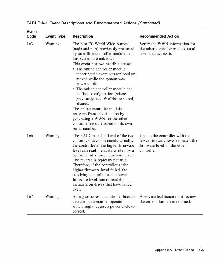
Appendix A Event Codes 129
163 Warning The host FC World Wide Names (node and port) previously presented by an offline controller module in this system are unknown.This event has two possible causes:• The online controller module
reporting the event was replaced or moved while the system was powered off.
• The online controller module had its flash configuration (where previously used WWNs are stored) cleared.
The online controller module recovers from this situation by generating a WWN for the other controller module based on its own serial number.
Verify the WWN information for the other controller module on all hosts that access it.
166 Warning The RAID metadata level of the two controllers does not match. Usually, the controller at the higher firmware level can read metadata written by a controller at a lower firmware level. The reverse is typically not true. Therefore, if the controller at the higher firmware level failed, the surviving controller at the lower firmware level cannot read the metadata on drives that have failed over.
Update the controller with the lower firmware level to match the firmware level on the other controller.
167 Warning A diagnostic test at controller bootup detected an abnormal operation, which might require a power cycle to correct.
A service technician must review the error information returned.
TABLE A-1 Event Descriptions and Recommended Actions (Continued)
Event Code Event Type Description Recommended Action

130 R/Evolution 5000 Series Troubleshooting Guide • October 2007
168 Error, warning, or informational
The specified SES alert condition was detected in the enclosure indicated.
Most voltage and temperature errors and warnings relate to the power-and-cooling module. See Table 7-8 for recommended action.
169 Informational The specified SES alert condition has been cleared in the enclosure indicated.
This event is generated when the problem that caused event 168 is cleared.
170 Informational The last rescan indicates that the specified enclosure was added to the system.
171 Informational The last rescan indicates that the specified enclosure was removed from the system.
172 Warning The specified vdisk has been quarantined because not all of its drives are available. There are not enough drives to be fault tolerant. The partial vdisk will be held in quarantine until it becomes fault tolerant.
• Ensure that all drives are latched into their slots and have power.
• During quarantine, the vdisk is not visible to the host. If after latching drives into their slot and powering up the vdisk, the vdisk is still quarantined, you can manually dequarantine the vdisk so that the host can see the vdisk. The vdisk is still critical.
When the vdisk has been dequarantined, event 173 is logged.
173 Informational The specified vdisk has been dequarantined.
174 Informational A device firmware update has completed.
175 Informational An Ethernet link has changed status (up/down).
176 Informational The error statistics for the specified drive have been reset.
TABLE A-1 Event Descriptions and Recommended Actions (Continued)
Event Code Event Type Description Recommended Action

Appendix A Event Codes 131
177 Informational The cache data for a missing volume was purged.
178 Informational A host has been added to the list of hosts that can access, or be denied access to, a LUN. An Add Host command will be successful.
179 Informational A host has been removed from the list of hosts that can access or be denied access to a LUN.
180 Informational Hosts can either access, or be denied access to, a LUN. This event indicates when a host list type is changed from include (to allow access) to exclude (to deny access) or from exclude to include.
181 Informational Advanced Network Interface Structure was set. The Management Controller configuration has been changed.
182 Informational All busses have been paused. I/O will not be performed on the drives until all busses are unpaused.
183 Informational All busses have been unpaused, meaning that I/O can resume. An unpause initiates a rescan.
185 Informational An EMP write command has completed.
186 Informational Enclosure parameters have been set.
187 Informational The write-back cache has been enabled due to a battery state change.
188 Informational Write-back cache has been disabled due to a battery state change.
189 Informational A disk channel that was previously degraded or failed is now healthy.
TABLE A-1 Event Descriptions and Recommended Actions (Continued)
Event Code Event Type Description Recommended Action

132 R/Evolution 5000 Series Troubleshooting Guide • October 2007
190–201 Informational Includes component-specific environmental indicator events generated by the auto-write-through feature when an environmental change occurs. If an auto-write-through-trigger condition has been met, write-back cache is disabled and event 188 is also logged. Once the fault is resolved, event 187 is logged to indicate that write-back mode has been restored.
202 Informational An auto-write-through-trigger condition has been cleared, causing write-back cache to be re-enabled. The environmental change is also logged. (See events 190–200 and 241 and 242.)
203 Warning An environmental change occurred that allows write-back cache to be enabled, but the auto-write-back preference is not set.The environmental change is also logged. (See events 190–200.)
Manually enable write-back cache.
204 Error, Warning, or informational
This event is generated by the hardware flush firmware whenever the boot processing firmware needs to inform the user about something.
Send the log file to the service technician for further diagnosis.
205 Informational The specified volume has been mapped or unmapped.
206 Informational Vdisk scrub has started.
207 Informational Vdisk scrub has completed.
208 Informational Drive scrub has started.
209 Informational Drive scrub has completed.
210 Informational All snapshot partitions have been deleted.
TABLE A-1 Event Descriptions and Recommended Actions (Continued)
Event Code Event Type Description Recommended Action

Appendix A Event Codes 133
211 Informational The Serial Attached SCSI (SAS) topology has changed; components were added or removed. The message specifies the number of elements in the SAS map, the number of expanders detected, the number of expansion levels on the native (local controller) side and on the partner (partner controller) side, and the number of device PHYs.
212 Informational All master volumes have been deleted.
213 Informational A standard volume has been converted to a master volume or a master volume has been converted to a standard volume.
214 Informational The creation of snapshots is complete. The number of snapshots is specified.
215 Informational A previously created batch of snapshots is now committed and ready for use. The number of snapshots is specified.
216 Informational The deletion of a batch of snapshots is complete.
217 Critical A super-capacitor failure has occurred on the controller.
A service technician must replace the super-capacitor pack on the controller reporting this event.
218 Warning The super-capacitor pack is near end of life.
A service technician must replace the super-capacitor pack on the controller reporting this event.
219 Informational Utility priority has changed.
220 Informational Master volume rollback operation has started.
221 Informational Snapshot reset is completed.
TABLE A-1 Event Descriptions and Recommended Actions (Continued)
Event Code Event Type Description Recommended Action

134 R/Evolution 5000 Series Troubleshooting Guide • October 2007
222 Informational Setting of the policy for the snap pool is complete. Policy is the action to be taken when the snap pool hits the threshold level.
223 Informational The threshold level for the snap pool has been set. Each snap pool has three policy levels that notify you when the snap pool is reaching decreasing capacity. Each policy level has an associated policy that specifies system behavior when the threshold is reached.
224 Informational A background master volume rollback operation has completed.
225 Critical Background master write copy-on-write operation has failed. There was an internal I/O error. Could not complete the write operation to the disk.
A probable hardware failure has prevented the software from operating successfully. Isolate and replace and failed hardware components. Once the hardware issues have been corrected, it might be necessary to delete all snapshots and restart the controller.
226 Critical A background master volume rollback failed to start due to inability to initialize the snap pool. All rollback is in a suspended state.
Make sure the snap pool and the vdisk on which this volume exists are online. Restart the rollback operation.
227 Critical Failure to execute rollback for a particular portion of the master volume.
Restart the rollback operation.
228 Critical Background rollback for a master volume failed to end due to inability to initialize the snap pool. All rollback is in a suspended state.
Make sure the snap pool and the vdisk on which this volume exists are online. Restart the rollback operation.
229 Warning The snap pool has reached the snap pool warning threshold.
The user can set up the policy for the snap pool.
TABLE A-1 Event Descriptions and Recommended Actions (Continued)
Event Code Event Type Description Recommended Action
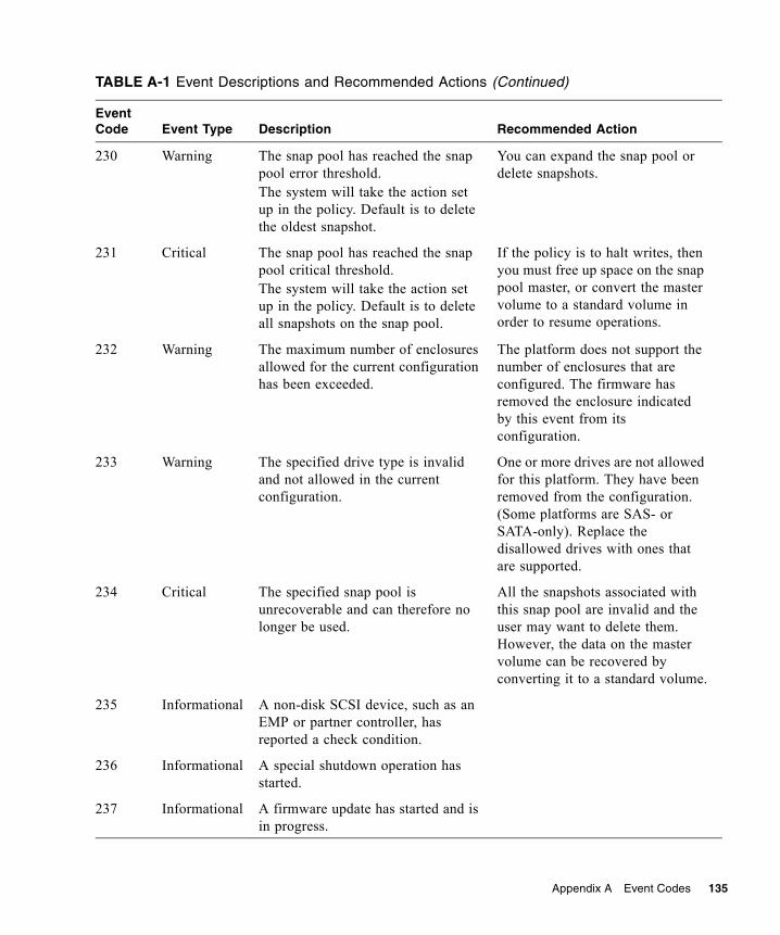
Appendix A Event Codes 135
230 Warning The snap pool has reached the snap pool error threshold.The system will take the action set up in the policy. Default is to delete the oldest snapshot.
You can expand the snap pool or delete snapshots.
231 Critical The snap pool has reached the snap pool critical threshold. The system will take the action set up in the policy. Default is to delete all snapshots on the snap pool.
If the policy is to halt writes, then you must free up space on the snap pool master, or convert the master volume to a standard volume in order to resume operations.
232 Warning The maximum number of enclosures allowed for the current configuration has been exceeded.
The platform does not support the number of enclosures that are configured. The firmware has removed the enclosure indicated by this event from its configuration.
233 Warning The specified drive type is invalid and not allowed in the current configuration.
One or more drives are not allowed for this platform. They have been removed from the configuration. (Some platforms are SAS- or SATA-only). Replace the disallowed drives with ones that are supported.
234 Critical The specified snap pool is unrecoverable and can therefore no longer be used.
All the snapshots associated with this snap pool are invalid and the user may want to delete them. However, the data on the master volume can be recovered by converting it to a standard volume.
235 Informational A non-disk SCSI device, such as an EMP or partner controller, has reported a check condition.
236 Informational A special shutdown operation has started.
237 Informational A firmware update has started and is in progress.
TABLE A-1 Event Descriptions and Recommended Actions (Continued)
Event Code Event Type Description Recommended Action

136 R/Evolution 5000 Series Troubleshooting Guide • October 2007
238 Warning An attempt to write license data failed due to an invalid license.
Check the license for what is allowed for the platform, make corrections as appropriate, and reinstall. If the license is invalid, the write will fail.
239 Warning A timeout has occurred while flushing the compact flash.
Cycle power and restart the system.If the error persists, save the log files and contact a service technician.
240 Warning A failure has occurred while flushing the compact flash.
Cycle power and restart the system.If the error persists, save the log files and contact a service technician.
241–242 Informational Compact flash status events generated by the auto-write-through feature whenever an environmental change occurs. If an auto-write-through-trigger condition has been met, write-back cache is disabled.
243 Informational A new RAID enclosure has been detected. This happens when a controller FRU is moved from one enclosure to another and the enclosure detects that the midplane WWN is different from the WWN it has in its local flash.
244 Warning There is not enough space to expand the specified snap pool.
Add more storage and retry the operation.
245 Informational An existing disk channel target device is not responding to SCSI discovery commands.
Check the indicated target device for bad hardware or bad cable, then initiate a rescan.
TABLE A-1 Event Descriptions and Recommended Actions (Continued)
Event Code Event Type Description Recommended Action

Appendix A Event Codes 137
246 Warning The coin battery is either not present, or it is not properly seated, or it has reached end of life. (The battery is a battery backup for the real-time (date/time) clock. In the event of a power failure, the date and time will revert to 1970 Jan 1 00:00:00.
The coin battery is on the controller module. A service technician must replace or reseat the battery.
247 Warning The FRU ID chip (SEEPROM) for the specified field replaceable unit (FRU) cannot be read. This chip contains information such as the worldwide name, SCSI ID, and branding information.
A service technician can reprogram the FRU ID.
248 Informational A valid feature license was successfully installed. See event 249 for details about each licensed feature.
249 Informational A valid license has been installed for the specified feature. This event is logged for each feature license installed.
250 Warning A license could not be installed (license is invalid).
Check license parameters against what is allowed for the platform and recreate the license using valid parameters, then reinstall.Review the readme file that came with the license.
252 Informational Snapshot write data on the specified master volume has been deleted.
256 Informational The specified snapshot has been created but not committed. A commit action is required before the snapshot can be used.
257 Informational The specified snapshot has been created and committed.
TABLE A-1 Event Descriptions and Recommended Actions (Continued)
Event Code Event Type Description Recommended Action

138 R/Evolution 5000 Series Troubleshooting Guide • October 2007
258 Informational The specified snapshot has been committed and is ready for use.
259 Informational Inband CAPI commands have been disabled.
260 Informational Inband CAPI commands have been enabled.
261 Informational Inband SES commands have been disabled.
262 Informational Inband SES commands have been enabled.
263 Warning The specified drive spare is missing. It was either removed or is not responding.
Replace the specified drive.
264 Informational The link speed of the port bypass circuit and interconnect mode has been set to the default.
265 Informational Port bypass circuits currently use the service port, which may limit the link speed or interconnect mode support.
Perform a system-level shutdown and restart. Note that this will cause all data to be unavailable for about 1 minute.
266 Informational A copy operation for the specified master volume has been aborted.
268 Informational A background copy operation for the specified master volume completed.
269 Informational A partner firmware update operation has started. This operation is used to copy firmware from one controller to the other to bring both controllers up to the same version of firmware.
270 Warning There is a problem reading or writing the persistent IP data from the FRU ID chip (SEEPROM), or if invalid data is read from the FRU ID chip.
Check the IP settings), and update them if they are incorrect.
TABLE A-1 Event Descriptions and Recommended Actions (Continued)
Event Code Event Type Description Recommended Action
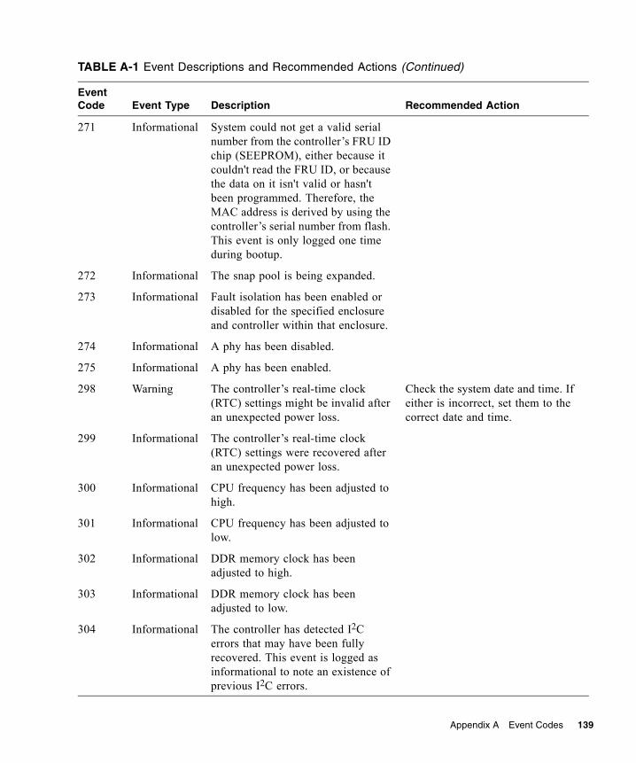
Appendix A Event Codes 139
271 Informational System could not get a valid serial number from the controller’s FRU ID chip (SEEPROM), either because it couldn't read the FRU ID, or because the data on it isn't valid or hasn't been programmed. Therefore, the MAC address is derived by using the controller’s serial number from flash. This event is only logged one time during bootup.
272 Informational The snap pool is being expanded.
273 Informational Fault isolation has been enabled or disabled for the specified enclosure and controller within that enclosure.
274 Informational A phy has been disabled.
275 Informational A phy has been enabled.
298 Warning The controller’s real-time clock (RTC) settings might be invalid after an unexpected power loss.
Check the system date and time. If either is incorrect, set them to the correct date and time.
299 Informational The controller’s real-time clock (RTC) settings were recovered after an unexpected power loss.
300 Informational CPU frequency has been adjusted to high.
301 Informational CPU frequency has been adjusted to low.
302 Informational DDR memory clock has been adjusted to high.
303 Informational DDR memory clock has been adjusted to low.
304 Informational The controller has detected I2C errors that may have been fully recovered. This event is logged as informational to note an existence of previous I2C errors.
TABLE A-1 Event Descriptions and Recommended Actions (Continued)
Event Code Event Type Description Recommended Action

140 R/Evolution 5000 Series Troubleshooting Guide • October 2007
305 Informational A serial number in Storage Controller flash memory is invalid. The valid serial number will be recovered automatically.
306 Informational An old serial number in Storage Controller flash memory has been updated to a new serial number.
307 Critical A temperature sensor on a controller FRU detected an over-temperature condition that caused the controller to shut down.
• Check that the storage system’s fans are running.
• Check that the ambient temperature is not too warm. See the System Site Planning Guide for temperature specifications.
• Check for any obstructions to the airflow.
• If none of the above explanations apply, replace the controller FRU that reported the error.
TABLE A-1 Event Descriptions and Recommended Actions (Continued)
Event Code Event Type Description Recommended Action

Appendix A Event Codes 141
Failover Reason CodesTABLE A-2 lists the reasons codes for failover. Use these reason codes along with the event messages to determine the reasons for a failover.
308 Informational The default host port speed has changed from 4 Gbit/sec to 2 Gbit/sec because the controller module has a Broadcom HIM.
309 Informational Normally when the Management Controller is started, the IP data is obtained from the SEEPROM where it is persisted. If the system is unable to write it to the SEEPROM the last time it changed, a flag is set in flash memory. This flag is set during startup, and if set, this event is logged and the IP data that is in flash memory is used. The only time that this would not be the correct IP data would be if the controller board was swapped and then whatever data is on the board’s flash memory is used.
310 Informational After a rescan, the controller completed back-end discovery and initialization of enclosure data has completed.
TABLE A-2 Failover Reason Codes
Code CAPI Event Event Message
0 CAPI_FR_NA Not applicable
1 CAPI_FR_FIRMWARE_INCOMPATIBLE Firmware incompatible
2 CAPI_FR_MODEL_INCOMPATIBLE Model incompatible
3 CAPI_FR_HEARTBEAT_LOST Heartbeat lost
4 CAPI_FR_MSG_TO_OTHER_FAILED Message to other failed
TABLE A-1 Event Descriptions and Recommended Actions (Continued)
Event Code Event Type Description Recommended Action

142 R/Evolution 5000 Series Troubleshooting Guide • October 2007
5 CAPI_FR_OTHER_NOT_PRESENT Other not present
6 CAPI_FR_CAPI_REQUESTED System call requested
7 CAPI_FR_FOC_REGISTER_ERROR FOC register error
8 CAPI_FR_MEMORY_SIZE_INCOMPATIBLE Cache memory size incompatible
9 CAPI_FR_BOOT_HANDSHAKE_TIMEOUT Boot handshake timeout
10 CAPI_FR_FIRMWARE_UPDATE Firmware update
11 CAPI_FR_SHUTDOWN Shutdown
12 CAPI_FR_REBOOTING Restarting
13 CAPI_FR_WRITE_UNIQUE_DATA Write unique data
14 CAPI_FR_OTHER_ORPHAN_DIRTY Orphan data for other
15 CAPI_FR_LOCK_MGR_LOST_COMM Lock manager lost communication
16 CAPI_FR_SAME_SERIAL_NUMBER Same serial number
17 CAPI_FR_CPLD_REVISION_MISMATCH CPLD revision mismatch
18 CAPI_FR_HARDWARE_INCOMPATIBLE Hardware incompatible
19 (Not applicable)
20 CAPI_FR_FORCED_OFFLINE Forced offline
21 CAPI_FR_PCIX_CONFIG_SEQ_TIMEOUT PCIX config sequence timeout
22 CAPI_FR_I2C_MSG_TO_OTHER_FAILED I2C message to other failed
23 CAPI_FR_OTHER_SHUTDOWN Other shutdown
24 CAPI_FR_OPERATING_MODE_MISMATCH Operating mode mismatch
25 CAPI_FR_SAS_LOCK_TIMEOUT SAS lock timeout
26 CAPI_FR_INTER_CTLR_MSG_TIMEOUT Intercontroller message timeout
27 CAPI_FR_PBC_FORWARD_INCOMPATIBLE Old PBC1 incompatible with new PBC configuration
0x7F CAPI_FR_UNKNOWN Unknown1 Port bypass circuit, also known as host port interconnect.
TABLE A-2 Failover Reason Codes (Continued)
Code CAPI Event Event Message

143
APPENDIX B
Troubleshooting Using the CLI
This appendix briefly describes CLI commands that are useful for troubleshooting storage system problems. For detailed information about command syntax and using the CLI, refer to the CLI Reference Manual.
Topics covered in this appendix include:■ “Viewing Command Help” on page 144■ “clear cache” on page 144■ “clear expander-status” on page 144■ “ping” on page 145■ “reset host-channel-link” on page 145■ “restart” on page 145■ “restore defaults” on page 145■ “set debug-log-parameters” on page 146■ “set expander-fault-isolation” on page 146■ “set expander-phy” on page 146■ “set led” on page 147■ “set protocols” on page 147■ “show debug-log” on page 148■ “show debug-log-parameters” on page 148■ “show enclosure-status” on page 148■ “show events” on page 149■ “show expander-status” on page 149■ “show frus” on page 149■ “show protocols” on page 149■ “show redundancy-mode” on page 150■ “trust” on page 150

144 R/Evolution 5000 Series Troubleshooting Guide • October 2007
Viewing Command HelpTo view brief descriptions of all commands that are available to the user level you logged in as, type:
To view help for a specific command, type either:
To view information about the syntax to use for specifying disk drives, virtual disks, volumes, and volume mapping, type:
clear cacheClears any unwritable cache in both RAID controllers for a specified volume, or any orphaned data for volumes that no longer exist. This command can be used with a dual-controller configuration only.
For details about using clear cache, refer to the CLI Reference Manual.
clear expander-status
Note – This command should only be used by service technicians, or with the advice of a service technician.
Clears the counters and status for SAS Expander Controller lanes. Counters and status can be reset to a good state for all enclosures, or for a specific enclosure whose status is ERROR as shown by the show expander-status command.
For details about using clear expander-status, refer to the CLI Reference Manual.
# help
# help command# command ?
# help syntax

Appendix B Troubleshooting Using the CLI 145
pingTests communication with a remote host. The remote host is specified by IP address. Ping sends ICMP echo response packets and waits for replies.
For details about using ping, refer to the CLI Reference Manual.
reset host-channel-linkIssues a loop initialization primitive (LIP) from specified controllers on specified channels. This command is for use with an FC system using FC-AL (loop) topology.
For details about using reset host-channel-link, refer to the CLI Reference Manual.
restartRestarts the RAID controller or the Management Controller in either or both controller modules.
If you restart a RAID controller, it attempts to shut down with a proper failover sequence, which includes stopping all I/O operations and flushing the write cache to disk, and then the controller restarts. The Management Controllers are not restarted so they can provide status information to external interfaces.
If you restart a Management Controller, communication with it is temporarily lost until it successfully restarts. If the restart fails, the partner Management Controller remains active with full ownership of operations and configuration information.
Caution – If you restart both controller modules, you and users lose access to the system and its data until the restart is complete.
For details about using restart, refer to the CLI Reference Manual.
restore defaults
Note – This command should only be used by service technicians, or with the advice of a service technician.

146 R/Evolution 5000 Series Troubleshooting Guide • October 2007
Restores the manufacturer's default configuration to the controllers. When the command informs you that the configuration has been restored, you must restart the RAID controllers and Management Controllers for the changes to take effect. After restarting the controllers, hosts might not be able to access volumes until you re-map them.
Caution – This command changes how the system operates and might require some reconfiguration to restore host access to volumes.
For details about using restore defaults, see the CLI Reference Manual.
set debug-log-parameters
Note – This command should only be used by service technicians, or with the advice of a service technician.
Sets the types of debug messages to include in the Storage Controller debug log. If multiple types are specified, use spaces to separate them and enclose the list in quotation marks (").
For details about using set debug-log-parameters, refer to the CLI Reference Manual.
set expander-fault-isolationWhen fault isolation is enabled, the Expander Controller will isolate PHYs that fail to meet certain criteria. When fault isolation is disabled, the errors are noted in the logs but the PHYs are not isolated.
For details about using set expander-fault-isolation, refer to the CLI Reference Manual.
set expander-phyThe Expander Controller will enable or disable (isolate) the specified PHY.
For details about using set expander-phy, refer to the CLI Reference Manual.

Appendix B Troubleshooting Using the CLI 147
set ledChanges the state of drive module or enclosure LEDs to help you locate devices. For a drive module, the Power/Activity/Fault LED will blink yellow. For an enclosure, the Unit Locator LED on the chassis ear and on each controller module will blink white.
For details about using set led, refer to the CLI Reference Manual.
set protocolsEnables or disables one or more of the following service and security protocols.■ http, for standard access to RAIDar■ https, for secure access to RAIDar■ telnet, for standard access to the CLI■ ssh, for secure access to the CLI■ ftp, an alternate interface for firmware upgrade■ Storage Management Initiative Specification (SMI-S)■ Simple Network Management Protocol (SNMP)■ Telnet service port 1023■ Telnet debug port 4048■ In-band CAPI management interface■ In-band SES management interface
For details about using set protocols, refer to the CLI Reference Manual.

148 R/Evolution 5000 Series Troubleshooting Guide • October 2007
show debug-log
Note – This command should only be used by service technicians, or with the advice of a service technician.
Shows the debug logs for the Storage Controller (SC), the Management Controller (MC), the semaphore trace, task logs, or all of them. If no logs are specified, all logs are shown.
For details about using show debug-log, refer to the CLI Reference Manual.
show debug-log-parameters
Note – This command should only be used by service technicians, or with the advice of a service technician.
Shows which debug message types are enabled (on) or disabled (off) for inclusion in the Storage Controller debug log.
For details about using show debug-log-parameters, refer to the CLI Reference Manual.
show enclosure-statusShows the status of system enclosures and their components. For each attached enclosure, the command shows general SCSI Enclosure Services (SES) information followed by component-specific information.
For details about using show enclosure-status, refer to the CLI Reference Manual.

Appendix B Troubleshooting Using the CLI 149
show eventsShows events for an enclosure, including events from each Management Controller and each Storage Controller. A separate set of event numbers is maintained for each controller module. Each event number is prefixed with a letter identifying the controller module that logged the event.
Events are listed from newest to oldest, based on a timestamp with one-second granularity; therefore the event log sequence matches the actual event sequence within about one second.
If SNMP is configured, events can be sent to SNMP traps.
For details about using show events, refer to the CLI Reference Manual.
show expander-status
Note – This command should only be used by service technicians, or with the advice of a service technician.
Shows diagnostic information relating to SAS Expander Controller physical channels, known as PHY lanes. Information is shown by controller for each enclosure.
For details about using show expander-status, refer to the CLI Reference Manual.
show frusShows information for all field-replaceable units (FRUs) in the controller enclosure and in any attached expansion enclosures. Some information reported is for use by service technicians.
For details about using show frus, refer to the CLI Reference Manual.
show protocolsShows which service and security protocols are enabled or disabled.
For details about using show protocols, refer to the CLI Reference Manual.

150 R/Evolution 5000 Series Troubleshooting Guide • October 2007
show redundancy-modeShows the redundancy status of the system.
For details about using show redundancy-mode, refer to the CLI Reference Manual.
trustEnables an offline virtual disk to be brought online for emergency data collection only. It must be enabled before each use.
Caution – This command can cause unstable operation and data loss if used improperly. It is intended for disaster recovery only.
The trust command re-synchronizes the time and date stamp and any other metadata on a bad disk drive. This makes the disk drive an active member of the virtual disk again. You might need to do this when:■ One or more disks of a virtual disk start up more slowly or were powered on after
the rest of the disks in the virtual disk. This causes the date and time stamps to differ, which the system interprets as a problem with the “late” disks. In this case, the virtual disk functions normally after being trusted.
■ A virtual disk is offline because a drive is failing, you have no data backup, and you want to try to recover the data from the virtual disk. In this case, trust may work, but only as long as the failing drive continues to operate.
When the “trusted” virtual disk is back online, back up its data and audit the data to make sure that it is intact. Then delete that virtual disk, create a new virtual disk, and restore data from the backup to the new virtual disk. Using a trusted virtual disk is only a disaster-recovery measure; the virtual disk has no tolerance for any additional failures.
For details about using trust, refer to the CLI Reference Manual.

151
Index
Aair management module, installing, 109architecture, system overview, 11
Bbad block
list size, displaying, 41reassignments, displaying, 41
boot handshake, 93
Ccables
identifying faultsexpansion enclosure side, 96host side, 96
cacheclearing, 54, 144size, 87
CLI help, view command, 144clock
reset, 113clock battery failure, 87clock reset, 113collecting data from an offline virtual disk, 150configuration settings, saving, 87controller module
conflicts, 86identifying faults, 85installing, 91only one boots, 86removing, 90replacing, 87shutting down, 89updating firmware, 95
controller redundancy mode, showing, 150cooling element
fan sensor descriptions, 79critical events, 71
selecting to monitor, 58critical state, virtual disk
preventing, 63
Ddata paths
isolating faults, 44SAS, architecture, 18
debug log, 75setting up, 75viewing, 76, 148
debug log parameterssetting, 146viewing, 148
debug utilitiesdebug log setup, 75view CAPI trace, 56view error buffers, 55view mgmt trace, 57viewing debug log, 76
default configuration settings, restoring, 145dequarantining, virtual disks, 64diagnostic manage-level only functions
clearing unwritable cache data, 54selecting individual events for notification, 58service debug, 60service interface, 60view CAPI trace, 56view error buffers, 55view mgmt trace, 57viewing the debug log, 76
disabled PHY, 45disaster recovery. See trust virtual diskdisk drives
See also drive modulesbad block reassignments, 41bad block size, 41capturing trend data, 41clearing metadata, 51

152 R/Evolution 5000 Series Troubleshooting Guide • October 2007
disk channel errors, 100error, 99event logs, 42firmware update, 102identifying faulty disks, 39LEDs, 105locating, 39media errors, 40metadata, 109mixing types, 103no response count, 40non-media errors, 41reviewing error statistics, 40
capturing trend data, 41spin-up retires, 40supported types, 15understanding errors, 98updating firmware, 102
disk error stats, 40dongle architecture
SAS, 15SATA, 15
drive modulesSee also disk drivesarchitecture, 15disk channel errors, 100disk drive errors, 99identifying faults, 97identifying location for removal, 105installing, 104, 107removing, 106, 107replacing, 106, 107, 109
Eenclosure ID
architecture, 13error, 94moving expansion enclosures, 94
enclosure status, showing, 148enclosure, replacing, 115errors
disk drive, 99displaying media errors, 40displaying non-media errors, 41PHY, 45reviewing disk drive statistics, 40
event logsdisabled PHY, 48
event type, 71reviewing, 42viewing using RAIDar, 72
event notificationselecting individual events to monitor, 58
eventsconfiguring notification, 58types, 71
events, showing, 149Expander Controller (EC) architecture, 16expander fault isolation, enabling or disabling, 146expander PHYs, enabling or disabling, 146expander status and error counters, clearing, 144expander status, showing, 149expansion module
enclosure ID does not update, 94identifying faults, 85installing, 91moving, 94removing, 90replacing, 87
Ffault isolation, 45Fault/Service Required LED
controller module, 93faults
identifyingcables, 96disk drive, 39drive modules, 97power-and-cooling modules, 112virtual disks, 110
isolatingdata path faults, 46, 49methodology, 23
FC host interface module architecture, 16firmware
controller partner, disabling automatic update, 94updating, 94
firmware update, automatic, 92FRU information, showing, 149FRUs
checking status, 32, 34determining health status, 36removing and replacing
Index 153
controller/expansion modules, 87drive modules, 103power-and-cooling modules, 113
replacingenclosure, 115
static electricity precautions, 85types of, 12
Hhost channel link, resetting, 145host channels, resetting, 50host interface module architecture, FC, 16
II/O
checking status, 37displaying timeout count, 40
icons, system status, 36informational events, 71
enabling, 71selecting to monitor, 58
installingair management modules, 109controller modules, 91drive modules, 107expansion modules, 91power-and-cooling modules, 115
internal clock, setting, 93IP address, persistent, 93
LLED
illuminating drive module Power/Activity/Fault, 147illuminating enclosure Unit Locator, 147
leftover disk drives, clearing metadata, 51LIP, issuing, 145LIP, remotely issuing on host channels, 50log information, saving, 64loop initialization primitive. See LIP
MManagement Controller (MC) architecture, 16Management Controller, restarting, 145metadata
clearing, 51deleting when replacing a disk module, 109
midplane, architecture, 12
Ppartner controller, disabling automatic update, 94partner firmware update, 92persistent IP address, 93PHY
disabled, 45errors, 45event logs, 48Expander Controller detail panel, 46fault isolation, 45fencing, 45internal data path faults, 46rescan disks, 45reset status, 48
physical layer interface. See PHY, 44pinging a remote host, 145power supply
clock, 113power-and-cooling module
architecture, 20identifying faults, 112installing, 115removing, 113replacing, 113, 115
protocols, service and securityenabling or disabling, 147showing status of, 149
RRAIDar
cache data status, 54checking I/O status, 37configuring event notification, 58debug utilities, 55disk error statistics, 40enable/disable trust virtual disk, 53icons, system status, 36locating a disk drive, 39reviewing event logs, 42status summary, 36using to troubleshoot, 35
real-time clock, 113rebuilding. See reconstructingreconstructing
redundant virtual disks, 43

154 R/Evolution 5000 Series Troubleshooting Guide • October 2007
recoveryclearing cache data, 54dequarantining a virtual disk, 63disaster
trust virtual disk, 52redundancy mode, showing, 150removing and replacing
power-and-cooling modules, 113replacing clock battery, 87rescan disks, 45reset PHY status, 48reset snapshot, 67resetting host channels, 50resetting the clock, 113
SSAS data path, architecture, 18SAS expander. See expander and Expander Controllersaving
log information, 64scheduling tasks, 67SEEPROM, data stored in, 12sensors
cooling fan, 79locating, 78power supply, 78temperature, 80voltage, 81
service debug, enabling, 60service interface
enabling, 60setting the time, 93shutting down controller module, 89SMART
displaying event count, 40snapshot, reset, 67spin-up retries, displaying, 40static electricity precautions, 85status
determining overall system health, 36disk, 40
status summary, 36Storage Controller (SC) architecture, 16Storage Controller, restarting, 145system architecture, overview, 11
Ttask scheduling, 67temperature warnings, resolving, 77trust virtual disk
caution, 52trusting an offline virtual disk, 150
Vview CAPI trace, 56view error buffers, 55view mgmt trace, 57virtual disk
reconstructing, 43trusting an offline, 150
virtual disksclearing cache data, 54dequarantining, 64disaster recovery, 52identifying faults, 110preventing critical state, 63redundant
reconstructing, 43voltage sensor descriptions, 81voltage warnings, resolving, 77
Wwarning events, 71
selecting to monitor, 58warnings, temperature, 77


