+ All Categories
Home > Documents > Rexroth MKD - AUTEC

Rexroth MKD - AUTEC

Date post: 14-Mar-2022
Category:
Upload: others
View: 17 times
Download: 0 times
Share this document with a friend
66
Rexroth IndraControl VCP 20 Industrial Hydraulics Electric Drives and Controls Linear Motion and Assembly Technologies Pneumatics Service Automation Mobile Hydraulics Rexroth MKD Synchronous motors R911272495 Edition 07 Project Planning Manual
Transcript

Rexroth IndraControl VCP 20

IndustrialHydraulics

Electric Drivesand Controls

Linear Motion and Assembly Technologies Pneumatics

ServiceAutomation

MobileHydraulics

Rexroth MKDSynchronous motors

R911272495Edition 07

Project Planning Manual

About this Documentation Synchronous Motors MKD

DOK-MOTOR*-MKD*******-PR07-EN-P

Rexroth Synchonous motors MKD

Project Planning Manual

DOK-MOTOR*-MKD*******-PR07-EN-P

Part No.: R911272495

Document Number: 120-1500-B302-07/EN

This documentation …

• explain the product qualities, possible applications, technical data,operating conditions and limits.

• Gives indications for the product choice, handling and operating.

Description ReleaseDate

Notes

DOK-MOTOR*-MKD*******-PRJ1-EN-P 09.96 1st edition

DOK-MOTOR*-MKD*******-PRJ2-EN-P 01.97 Revison

DOK-MOTOR*-MKD*******-PR05-EN-P 02.99 Revison

DOK-MOTOR*-MKD*******-PR06-EN-P 06.02 Revison

DOK-MOTOR*-MKD*******-PR07-EN-P 05.04 Revison

2004 Bosch Rexroth AG

Copying this document, giving it to others and the use or communicationof the contents thereof without express authority, are forbidden.Offenders are liable for the payment of damages. All rights are reservedin the event of the grant of a patent or the registration of a utility modelor design (DIN 34-1).

The specified data is for product description purposes only and may notbe deemed to be guaranteed unless expressly confirmed in the contract.All rights are reserved with respect to the content of this documentationand the availability of the product.

Bosch Rexroth AGBgm.-Dr.-Nebel-Str. 2 • D-97816 Lohr a. Main

Telephone +49 (0)93 52/40-0 • Tx 68 94 21 • Fax +49 (0)93 52/40-48 85

http://www.boschrexroth.com/

Dept. BRC/EDM2 (JW)

This document has been printed on chlorine-free bleached paper.

Title

Type of Documentation

Document Typecode

Internal File Reference

Purpose of Documentation

Record of Revisions

Copyright

Validity

Published by

Note

Synchronous Motors MKD Contents I

DOK-MOTOR*-MKD*******-PR07-EN-P

Contents

1 Introduction 1-1

1.1 Product Presentation.................................................................................................................1-1

1.2 About this Documentation..........................................................................................................1-4

2 Important Instructions on Use 2-1

2.1 Intended Use.............................................................................................................................2-1

Introduction .........................................................................................................................2-1

Fields of Use and Application ..............................................................................................2-2

2.2 Non-Intended Use .....................................................................................................................2-2

3 Safety Instructions for Electric Drives and Controls 3-1

3.1 Introduction ...............................................................................................................................3-1

3.2 Explanations .............................................................................................................................3-1

3.3 Hazards by Improper Use..........................................................................................................3-2

3.4 General Information...................................................................................................................3-3

3.5 Protection Against Contact with Electrical Parts .........................................................................3-5

3.6 Protection Against Electric Shock by Protective Low Voltage (PELV).........................................3-6

3.7 Protection Against Dangerous Movements ................................................................................3-7

3.8 Protection Against Magnetic and Electromagnetic Fields During Operation and Mounting..........3-9

3.9 Protection Against Contact with Hot Parts................................................................................3-10

3.10 Protection During Handling and Mounting................................................................................3-11

3.11 Battery Safety..........................................................................................................................3-12

3.12 Protection Against Pressurized Systems..................................................................................3-13

4 MKD Type Code 4-1

5 General Notes on Technical Data 5-1

5.1 60-K and 100-K Parameters ......................................................................................................5-1

5.2 Operating Modes.......................................................................................................................5-2

5.3 Definition of Parameters ............................................................................................................5-3

5.4 Sample Curve ...........................................................................................................................5-5

6 MKD025 6-1

6.1 Technical Data ..........................................................................................................................6-1

Holding brake ......................................................................................................................6-4

6.2 Type code – Ordering type ........................................................................................................6-5

6.3 Speed – Torque – Caracteristics ...............................................................................................6-6

6.4 Shaft Load ................................................................................................................................6-8

II Contents Synchronous Motors MKD

DOK-MOTOR*-MKD*******-PR07-EN-P

6.5 Dimensions ...............................................................................................................................6-9

7 MKD041 7-1

7.1 Technical Data ..........................................................................................................................7-1

Holding Brake......................................................................................................................7-4

7.2 Type code – Ordering Name .....................................................................................................7-5

7.3 Speed – Torque – Characteristics..............................................................................................7-6

7.4 Shaft Load ................................................................................................................................7-8

7.5 Dimensions ...............................................................................................................................7-9

8 MKD071 8-1

8.1 Technical Data ..........................................................................................................................8-1

Holding brake ......................................................................................................................8-4

8.2 Type code – Ordering Name .....................................................................................................8-5

8.3 Speed – Torque – Characteristics..............................................................................................8-6

8.4 Shaft Load ................................................................................................................................8-8

8.5 Dimensions ...............................................................................................................................8-9

8.6 Blower Units............................................................................................................................8-11

9 MKD090 9-1

9.1 Technical Data ..........................................................................................................................9-1

Holding Brake......................................................................................................................9-5

9.2 Type code – Ordering Name .....................................................................................................9-6

9.3 Speed – Torque – Characteristics..............................................................................................9-7

9.4 Shaft Load ................................................................................................................................9-9

9.5 Dimensions .............................................................................................................................9-10

9.6 Blower Units............................................................................................................................9-11

10 MKD112 10-1

10.1 Technical Data ........................................................................................................................10-1

Holding Brake....................................................................................................................10-9

10.2 Type code – Ordering Name .................................................................................................10-10

10.3 Speed – Torque – Characteristics..........................................................................................10-11

10.4 Shaft Load ............................................................................................................................10-14

10.5 Dimensions ...........................................................................................................................10-15

10.6 Blower Units..........................................................................................................................10-17

11 Accessories 11-1

11.1 Sealing Air Connection Accessories ........................................................................................11-1

11.2 Gearings .................................................................................................................................11-2

GTS, GTP Planetary Gearings...........................................................................................11-2

Screw Gearings 058 ..........................................................................................................11-3

12 Connection System 12-1

12.1 Overview of Connections.........................................................................................................12-1

12.2 Motors with connector box.......................................................................................................12-2

Synchronous Motors MKD Contents III

DOK-MOTOR*-MKD*******-PR07-EN-P

Connection diagram ..........................................................................................................12-2

12.3 Motors with connector receptacle ............................................................................................12-4

Connection diagram ..........................................................................................................12-4

12.4 Blower connector ....................................................................................................................12-6

Type (1) ............................................................................................................................12-6

Connecting and mounting the blower .................................................................................12-7

12.5 Connection Cable....................................................................................................................12-8

Dimensioning of power cable.............................................................................................12-8

Selection of connection cable ............................................................................................12-9

13 Application Instructions 13-1

13.1 Operating Conditions...............................................................................................................13-1

Setup Height and Ambient Temperature ............................................................................13-1

Vibration and Shock Loads................................................................................................13-2

13.2 Degree of protection................................................................................................................13-3

Option sealing air “sealing air: principle” connection...........................................................13-4

Selecting the Degree of Protection.....................................................................................13-5

13.3 Design and Installation Positions .............................................................................................13-6

Prime Coat and Housing Varnish.......................................................................................13-6

13.4 Blower.....................................................................................................................................13-7

13.5 Holding Brakes........................................................................................................................13-8

13.6 Output Shaft and Motor Bearing ..............................................................................................13-9

Plain shaft .........................................................................................................................13-9

Output shaft with key .........................................................................................................13-9

Output Shaft with Shaft Sealing Ring ...............................................................................13-10

Bearings and Shaft Load .................................................................................................13-11

13.7 Motor Encoder.......................................................................................................................13-13

13.8 Acceptances, Approvals ........................................................................................................13-14

CE mark..........................................................................................................................13-14

UR, cUR Listing...............................................................................................................13-14

14 Handling 14-1

14.1 Identifying the Goods ..............................................................................................................14-1

14.2 Type Labels ............................................................................................................................14-1

14.3 Instructions on the Packing......................................................................................................14-2

14.4 Storage ...................................................................................................................................14-3

14.5 Transport and Handling ...........................................................................................................14-3

15 Assembly 15-1

15.1 Skilled Technical Personnel.....................................................................................................15-1

15.2 Mounting the Motor .................................................................................................................15-1

15.3 Connecting the Motor ..............................................................................................................15-3

Motor with connection box .................................................................................................15-4

Motors with plug-in connectors ..........................................................................................15-6

16 Startup, Operation, and Maintenance 16-1

IV Contents Synchronous Motors MKD

DOK-MOTOR*-MKD*******-PR07-EN-P

16.1 Startup ....................................................................................................................................16-1

16.2 Operation ................................................................................................................................16-1

16.3 Maintenance ...........................................................................................................................16-2

Cleaning............................................................................................................................16-2

Bearings............................................................................................................................16-2

Connection Cable..............................................................................................................16-2

Holding brake ....................................................................................................................16-3

Changing the battery .........................................................................................................16-4

17 Appendix 17-1

17.1 List of Standards .....................................................................................................................17-2

17.2 Selecting Power Cables ..........................................................................................................17-3

INS0680 1,0mm² ...............................................................................................................17-5

INS0542 1,0mm² ..............................................................................................................17-6

INS0480 1,5mm² ..............................................................................................................17-7

INS0480 2,5mm² ..............................................................................................................17-8

INS0480 4,0mm² ..............................................................................................................17-9

INS0480 6,0mm² ............................................................................................................17-10

INS0480 10,0mm² ..........................................................................................................17-11

INS0380 6,0mm² ............................................................................................................17-12

INS0380 10,0mm² ..........................................................................................................17-13

INS0380 16,0mm² ..........................................................................................................17-14

17.3 Selecting Encoder Cables .....................................................................................................17-15

18 Index 18-1

19 Service & Support 19-1

19.1 Helpdesk.................................................................................................................................19-1

19.2 Service-Hotline........................................................................................................................19-1

19.3 Internet....................................................................................................................................19-1

19.4 Vor der Kontaktaufnahme... - Before contacting us... ...............................................................19-1

19.5 Kundenbetreuungsstellen - Sales & Service Facilities..............................................................19-2

Synchronous Motors MKD Introduction 1-1

DOK-MOTOR*-MKD*******-PR07-EN-P Version7.0 19.05.2004

1 IntroductionThis chapter describes how to use the present documentation (refer tothe chapter entitled “About this Documentation”) and includes a generalrepresentation of the product in Chapter 1.1.

1.1 Product Presentation

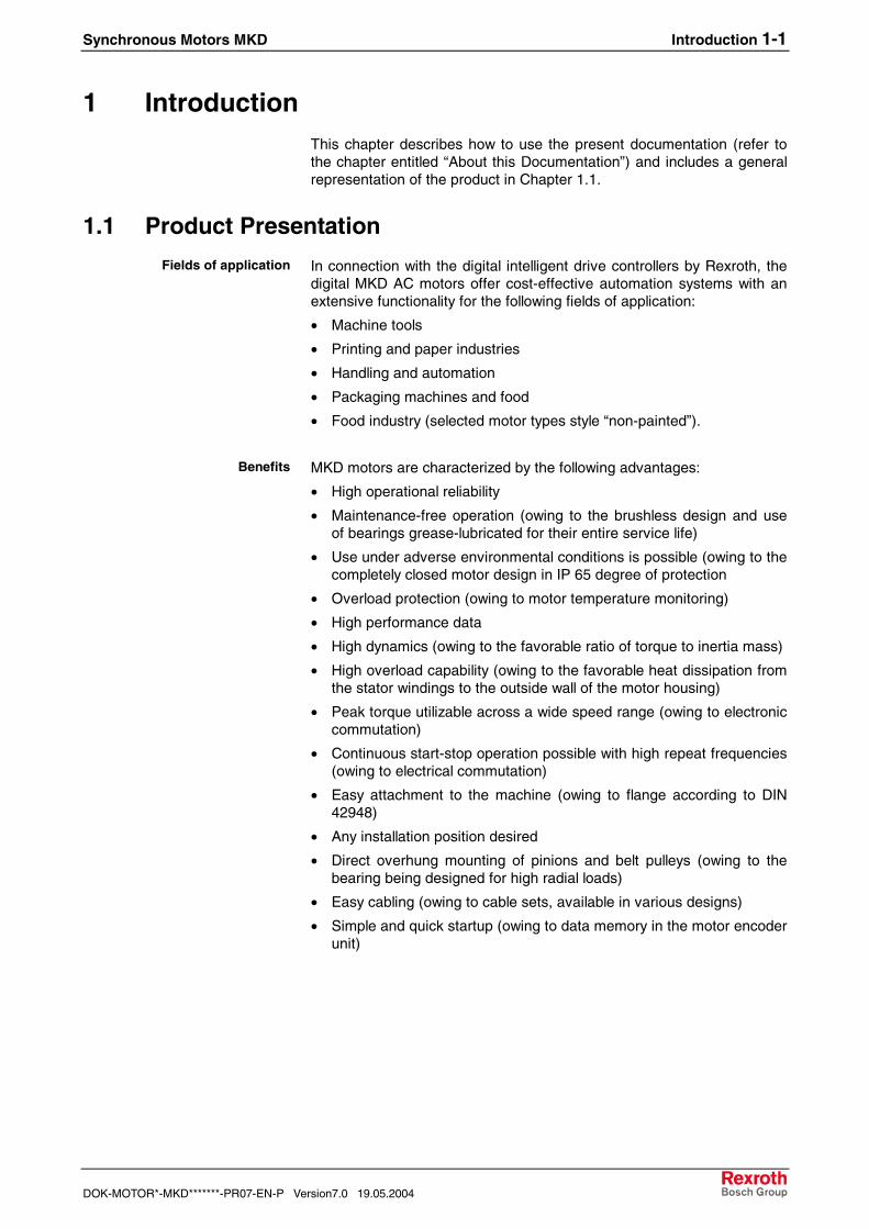
In connection with the digital intelligent drive controllers by Rexroth, thedigital MKD AC motors offer cost-effective automation systems with anextensive functionality for the following fields of application:

• Machine tools

• Printing and paper industries

• Handling and automation

• Packaging machines and food

• Food industry (selected motor types style “non-painted”).

MKD motors are characterized by the following advantages:

• High operational reliability

• Maintenance-free operation (owing to the brushless design and useof bearings grease-lubricated for their entire service life)

• Use under adverse environmental conditions is possible (owing to thecompletely closed motor design in IP 65 degree of protection

• Overload protection (owing to motor temperature monitoring)

• High performance data

• High dynamics (owing to the favorable ratio of torque to inertia mass)

• High overload capability (owing to the favorable heat dissipation fromthe stator windings to the outside wall of the motor housing)

• Peak torque utilizable across a wide speed range (owing to electroniccommutation)

• Continuous start-stop operation possible with high repeat frequencies(owing to electrical commutation)

• Easy attachment to the machine (owing to flange according to DIN42948)

• Any installation position desired

• Direct overhung mounting of pinions and belt pulleys (owing to thebearing being designed for high radial loads)

• Easy cabling (owing to cable sets, available in various designs)

• Simple and quick startup (owing to data memory in the motor encoderunit)

Fields of application

Benefits

1-2 Introduction Synchronous Motors MKD

19.05.2004 Version7.0 DOK-MOTOR*-MKD*******-PR07-EN-P

Motors with the following continuous torques at standstill are available:

MKD_A

MKD_B

Speed in min-1

MdNin Nm

MKD025

MKD0900

surfacecooled

MKD_A

MKD_B

MKD_D

20

40

60

80

100

MKD_C

MdN in Nm

Speed in min-1

Size

Size

naturalconvection

o11mk81p.fh7

14

12

10

8

6

4

2

0MKD041 MKD071

MKD112

2500

3200

3200

4000

2500

3200

4000

2000

3500

4000

2000

3500

4000

with

out p

aint

edco

atin

g

9000

6000

6000

2500

4500

2500

4500

with

out p

aint

edco

atin

g

Fig. 1-1: Continuous torques at standstill of the available MKD motors

Note: For Information about MKD motors in ATEX-Design(Ex II3 GDx EEx NA II T155°C) use the DocumentationDOK-MOTOR*-MKD*EXGIIK3-PRxx-DE-P.

Performance overview

14-2 Handling Synchronous Motors MKD

19.05.2004 Version7.0 DOK-MOTOR*-MKD*******-PR07-EN-P

Cable sets by Rexroth are identified by a cable type label (label at theend of the cable). The cable type label specifies the ordering name aswell as the length of the cable.

146546-38687613

IKG4070 15.00 m

19.04.98 230

Type nameof the cable set

Date offunctional check

Internal code number

Internal code number

Length in meters

cab_label_en.fh7

Fig. 14-2: Cable type label

The name of the raw cable type is printed on the cable sheath. Whenordering raw cables, the desired length in meters must be specified inaddition to the raw cable type.

REXROTH INDRAMAT INK0606-00-31 2299 E...

Supplier-specificUL/CSA file and style number

internal code number

raw cable type

Manufactor rohkabel_en.fh7

Fig. 14-3: Raw cable name

14.3 Instructions on the Packing

Instructions on storage, transport and handling of the parcels are printedon the packing. It is absolutely necessary that these instructions beobserved.

AchtungHochwertige Elektronik

AttentionFragile Electronic

Vor Nässe schützen Nicht werfennicht belasten Nicht kantenDo not apply load Do not tipDo not drop Keep dry

fragile.fh7

Fig. 14-4: Instructions on storage, transport and handling on the packing

Cable sets

Non-prepared cablesRaw cable type

Synchronous Motors MKD Handling 14-3

DOK-MOTOR*-MKD*******-PR07-EN-P Version7.0 19.05.2004

14.4 Storage

WARNING

Damage to motor and loss of warranty possible!Any improper storage may cause damage to the motor.

In addition, any warranty claim will expire.⇒ For that reason, please observe the following

instructions.

The following conditions must be kept during storage:

• Permissible range of temperature: -20° C up to +80 °C.

• Store motors at dry places which are free from dust and vibrations.

• Store motors horizontally.

• Do not remove the plastic protective sleeve on the drive shaft. Itprotects the shaft from moisture and mechanical damage.

14.5 Transport and Handling

WARNING

Damage to motor and loss of warranty possible!Improper transport and handling may cause damage to

the motor. In addition, any warranty claim will expire.⇒ For that reason, please observe the following

instructions.

The following conditions must be kept during transport and handling:

• Use the appropriate means for transport. Take the weight of thecomponents into consideration (weights are specified in the chapterspertaining to the various motors, in the sections on technical dataand/or on the type label of the motor).

• Provide for shock absorption, if strong vibrations may occur duringtransport. Please also observe the limits specified in Chapter 12.5,“Maximum Vibration and Shock Loads”.

• Transport only in horizontal position.

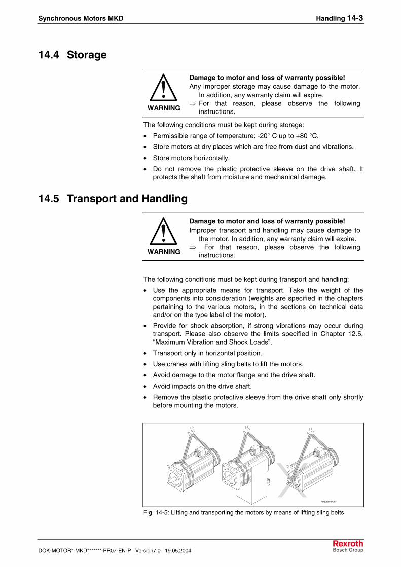
• Use cranes with lifting sling belts to lift the motors.

• Avoid damage to the motor flange and the drive shaft.

• Avoid impacts on the drive shaft.

• Remove the plastic protective sleeve from the drive shaft only shortlybefore mounting the motors.

mhd_heben.fh7

Fig. 14-5: Lifting and transporting the motors by means of lifting sling belts

14-4 Handling Synchronous Motors MKD

19.05.2004 Version7.0 DOK-MOTOR*-MKD*******-PR07-EN-P

Synchronous Motors MKD Assembly 15-1

DOK-MOTOR*-MKD*******-PR07-EN-P Version7.0 19.05.2004

15 Assembly

15.1 Skilled Technical Personnel

Any work on the system and on the drives or in their vicinity may only becarried out by appropriately trained technical personnel. The owner ofthe system must ensure that all persons carrying out

• installation work,

• maintenance measures, or

• operation activities

on the system are adequately familiar with the contents of thisdocumentation as well as with all warnings and precautionary measurescontained therein. Qualified technical personnel must have been trainedand instructed and are authorized to activate and deactivate, ground andmark electric circuits and equipment according to the safety rules andregulations. Qualified technical personnel must possess the appropriatesafety equipment and have been trained in first aid.

15.2 Mounting the Motor

Observe all warnings and safety advices mentioned in Chapter 3. Thisminimizes the risk of accidents and damage to the system or the motor.

Do all handling advices carefully. This ensures correct mounting anddismounting of the components.

MKD motors comply with design B5 in accordance with DIN 42950, Part1, ed. 08.77. Please refer to the dimensional sheets in Chapters 6 to 13for all relevant dimensional details.

General for mounting

15-2 Assembly Synchronous Motors MKD

19.05.2004 Version7.0 DOK-MOTOR*-MKD*******-PR07-EN-P

Before mounting:1. Procure tools, auxiliary materials, measuring and test equipment.2. Control all components if they are clean.3. Proof all components if they are obviously damaged. Defective

components may not be mounted.4. Ensure that mounting can be done in a dry and clean environment.5. Ensure that the holder for the motor flange is without burrs.

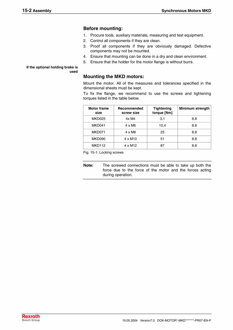
Mounting the MKD motors:Mount the motor. All of the measures and tolerances specified in thedimensional sheets must be kept.To fix the flange, we recommend to use the screws and tighteningtorques listed in the table below.

Motor framesize

Recommendedscrew size

Tighteningtorque [Nm]

Minimum strength

MKD025 4x M4 3,1 8.8

MKD041 4 x M6 10,4 8.8

MKD071 4 x M8 25 8.8

MKD090 4 x M10 51 8.8

MKD112 4 x M12 87 8.8

Fig. 15-1: Locking screws

Note: The screwed connections must be able to take up both theforce due to the force of the motor and the forces actingduring operation.

If the optional holding brake isused

Synchronous Motors MKD Assembly 15-3

DOK-MOTOR*-MKD*******-PR07-EN-P Version7.0 19.05.2004

15.3 Connecting the Motor

After having mounted the motor mechanically as specified, proceed toconnecting the motor.

DANGER

Danger to life by electric voltage! Handlingwithin the range of live parts is extremelydangerous. Therefore:⇒ Any work required on the electric system may only be

carried out by skilled electricians. It is absolutelynecessary to use electric tools.

⇒ Before starting work, the system must be de-energized and the power switch be secured againstunintentional or unauthorized re-energization.

⇒ Before starting work, the appropriate measuringequipment must be used to check whether parts ofthe system are still applied to residual voltage (e.g.caused by capacitors, etc.). If yes, wait until theseparts have discharged.

WARNING

Injuries to persons or property are possible!Interrupting or connecting live lines may causeunpredictable dangerous situations or lead tophysical damage. Therefore:⇒ Connect and disconnect plug connectors only when

they are dry and de-energized.⇒ During operation of the system, all plug connectors

must be securely tightened.

WARNING

Risk of short-circuit caused by liquid coolant orlubricant! Short-circuits of live lines may causeunpredictable dangerous situations or lead tophysical damage. Therefore:⇒ Provide open mating sides of power plug connectors

with safety caps when installing or replacing drivecomponents, if you cannot exclude that they might bemoistened with liquid coolant or lubricant.

The connection diagrams by Rexroth are exclusively intended for thepreparation of system circuit diagrams!

⇒ Connect the motor as specified in the machine manufacturer’ssystem circuit diagram! Refer to the connection diagram in Chapterfor support.

15-4 Assembly Synchronous Motors MKD

19.05.2004 Version7.0 DOK-MOTOR*-MKD*******-PR07-EN-P

Motor with connection box

WARNING

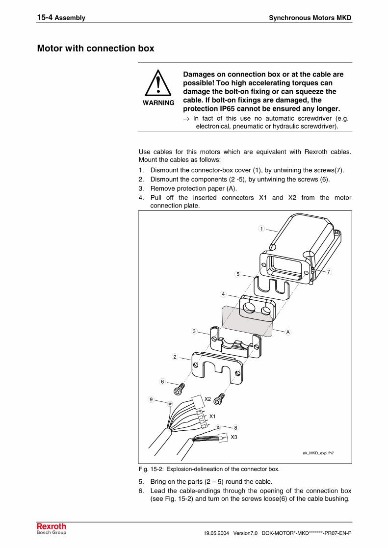
Damages on connection box or at the cable arepossible! Too high accelerating torques candamage the bolt-on fixing or can squeeze thecable. If bolt-on fixings are damaged, theprotection IP65 cannot be ensured any longer.⇒ In fact of this use no automatic screwdriver (e.g.

electronical, pneumatic or hydraulic screwdriver).

Use cables for this motors which are equivalent with Rexroth cables.Mount the cables as follows:

1. Dismount the connector-box cover (1), by untwining the screws(7).2. Dismount the components (2 -5), by untwining the screws (6).3. Remove protection paper (A).4. Pull off the inserted connectors X1 and X2 from the motor

connection plate.

ak_MKD_expl.fh7

9

6

2

3

1

7

8

X3

X1

X2

5

4

A

Fig. 15-2: Explosion-delineation of the connector box.

5. Bring on the parts (2 – 5) round the cable.6. Lead the cable-endings through the opening of the connection box

(see Fig. 15-2) and turn on the screws loose(6) of the cable bushing.

Synchronous Motors MKD Assembly 15-5

DOK-MOTOR*-MKD*******-PR07-EN-P Version7.0 19.05.2004

Encoder cablePower cable

16

2,5 Nm

2,5 Nm1,3 Nm

a05mk81p_en.fh7

Plugin terminalPart. No.: 259 698

Plugin terminalPart. No.: 259 700

16

X1

X2

X3

90

90

ConnectorPart. No.: 236 813

Crimping contact10 x Part. No.: 260 765

9 8

6

X5

Fig. 15-3: Entrance of power and conductor cables

7. Pull back the cable until the shrinking sleeve penetrates the inside ofthe connection box by about 16mm (see Fig. 15-3).

8. Tighten screws (6) with 2,5 Nm.9. Tighten up grounding ring terminals (8) and (9) with 1.3 Nm to

connector box lid (1).10. Insert connectors X1, X2 and the encoder connector X3 into

appropriate position on the motor panel.11. Tighten screws in the terminal X1 with 0.5 Nm.12. Place the connector box into output direction.13. Make sure that no cable cores are squezed or damaged and tighten

the connector box into place with 2.5 Nm.

Adjust the output directionThe connector box lid can be turned 180° when it is mounted. Thismeans the output direction can be set to:

• side A or

• side B.

Note: The cable output direction is side B at the time of delivery.

The cable output direction can be selected when mounting power andencoder cable.

15-6 Assembly Synchronous Motors MKD

19.05.2004 Version7.0 DOK-MOTOR*-MKD*******-PR07-EN-P

Motors with plug-in connectors

Power connectorWhen fitting the INS0681 power connector with thread, proceed asfollows:

1. Put the power connector onto the thread of the connection housingin the correct position.

2. Tighten the union nut of the power connector manually. By leadingthe cable in further, the power connector can be steadily put to itsfinal position.

3. Tighten the union nut as securely as you can manually. When fitting the INS0381 or INS0481 power connector with bayonetlock, proceed as follows:

1. Put the power connector onto the bayonet lock of the connectionhousing in the correct position.

2. Turn the union nut of the power connector in manually until it snapsinto the final position (i.e. when the red dots comply with the redtriangles).

Encoder connectorWhen fitting the encoder connectors, proceed as follows:

1. Put the encoder connector onto the thread of the connection housingin the correct position.

2. Tighten the union nut of the power connector manually. By leadingthe cable in further, the encoder connector can be steadily put to itsfinal position.

3. Tighten the union nut as securely as you can manually.

Power connectors for MKD025

Power connector for MKD112

Encoder connector

Synchronous Motors MKD Assembly 15-7

DOK-MOTOR*-MKD*******-PR07-EN-P Version7.0 19.05.2004

Adjust the output direction of power connectorThe output direction on MKD025 motors can be chosen when mountingthe power connector. The flange sockets are designed such that theycan be turned (angle of rotation of 270 degrees).

Adjustment of the desired connector output direction is described below.

Note: Do not use any tools (e.g. tongs or pliers or screwdrivers) toturn the motor flange socket. Mechanical damage to theflange socket when using tools cannot be excluded.

The motor flange socket can be turned easily if an appropriate plug hasbeen connected. Owing to the leverage of the connected plug, the flangesocket can be turned manually to the desired output direction.

Proceed as follows:

1. Connect the motor power cable to the flange socket.2. Put the flange socket to the desired output direction by turning the

connected plug. The desired output direction is set.

Note: Whenever the flange socket is turned, the holding torque inthe set position is reduced. To ensure the required holdingtorque of the flange socket, the output direction should bechanged no more than 5 times!

It is not necessary to “rebuild” the flange socket (i.e. dismounting andmounting the flange socket, relocated by 90 degrees). The followingproblems and risks can arise should the flange socket be “rebuilt”:

• The O-ring seal between the flange socket and the motor housing isnot ensured any longer.

• The tightening torques prescribed are, perhaps, not kept.

• The TFL coating (screw locking element) of the locking screws willwear by unscrewing, thus becoming ineffective.

Note: No warranty!

• If the cable output direction is changed by “rebuilding” the flangesocket, the warranty for the overall drive system given by Rexroth willexpire. The cable output direction may only be changed by turning theflange socket.

Changing the output directionon MKD025

15-8 Assembly Synchronous Motors MKD

19.05.2004 Version7.0 DOK-MOTOR*-MKD*******-PR07-EN-P

The flange socket on MKD112 motors can be turned by steps in 90°(output direction A,B, L, R see type code).

To achieve this, proceed as follows:

1. Loosen the two locking screws (4) and remove the cover of theflange socket (2).

2. Loosen the four locking screws (3).3. Now turn the flange socket housing (1) into appropriate position (by

steps in 90°).4. Ensure that cable strands are prevented from being damaged or

tensioned unnecessarily.5. Retighten the four locking screws (3) (tightening torque: 3.1 Nm

±10%).6. Ensure that, when retightening the screws, cable strands and the

seal are prevented from being damaged.7. Reattach the cover of the flange socket (2) to the connector housing

(1) and retighten the two locking screws (4) (tightening torque: 3.1Nm ±10%).

O-ring

3

4 2 1

INS0x81en.fh7

(1): Flange socket housing(2): Flange socket lid(3): Flange socket housing screws(4): Flange socket lid screws

Fig. 15-4: Flange socket

Note: The connector output direction can be selected upon orderingby specifying it accordingly in the type code (output directionA, B, L, R).

Changing the output directionon MKD112

Synchronous Motors MKD Assembly 15-9

DOK-MOTOR*-MKD*******-PR07-EN-P Version7.0 19.05.2004

Adjust the output direction of encoder connectorThe output direction on MKD025 motors can be chosen. The flangesockets are designed such that they can be turned (angle of rotation of270 degrees).

Adjustment of the desired connector output direction is described below.

Noto: Do not use any tools (e.g. tongs or pliers or screwdrivers) toturn the motor flange socket. Mechanical damage to theflange socket cannot be excluded.

The motor flange socket can be turned easily if an appropriate plug hasbeen connected. Owing to the leverage of the connected plug, the flangesocket can be turned manually to the desired output direction.

Proceed as follows:

1. Connect the encoder cable to the flange socket.2. Put the flange socket to the desired output direction by turning the

connected cable. The desired output direction is set.

Note: Whenever the flange socket is turned, the holding torque inthe set position is reduced. To ensure the required holdingtorque of the flange socket, the output direction should bechanged no more than 5 times!

It is not necessary to “rebuild” the flange socket (i.e. dismounting andmounting the flange socket, relocated by 90 degrees). The followingproblems and risks can arise should the flange socket be “rebuilt”:

• The O-ring seal between the flange socket and the motor housing isnot ensured any longer.

• The tightening torques prescribed are, perhaps, not kept.

• The TFL coating (screw locking element) of the locking screws willwear by unscrewing, thus becoming ineffective.

Note: No warranty!

• If the cable output direction is changed by “rebuilding” the flangesocket, the warranty for the overall drive system given by Rexroth willexpire. The cable output direction may only be changed by turning theflange socket.

Changing the output directionon MKD025

15-10 Assembly Synchronous Motors MKD

19.05.2004 Version7.0 DOK-MOTOR*-MKD*******-PR07-EN-P

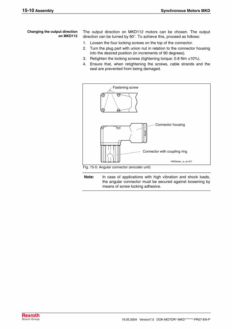
The output direction on MKD112 motors can be chosen. The outputdirection can be turned by 90°. To achieve this, proceed as follows:

1. Loosen the four locking screws on the top of the connector.2. Turn the plug part with union nut in relation to the connector housing

into the desired position (in increments of 90 degrees).3. Retighten the locking screws (tightening torque: 0.8 Nm ±10%).4. Ensure that, when retightening the screws, cable strands and the

seal are prevented from being damaged.

INSGeber_w_en.fh7

Fastening screw

Connector housing

Connector with coupling ring

Fig. 15-5: Angular connector (encoder unit)

Note: In case of applications with high vibration and shock loads,the angular connector must be secured against loosening bymeans of screw locking adhesive.

Changing the output directionon MKD112

Synchronous Motors MKD Startup, Operation, and Maintenance 16-1

DOK-MOTOR*-MKD*******-PR07-EN-P Version7.0 19.05.2004

16 Startup, Operation, and Maintenance

16.1 Startup

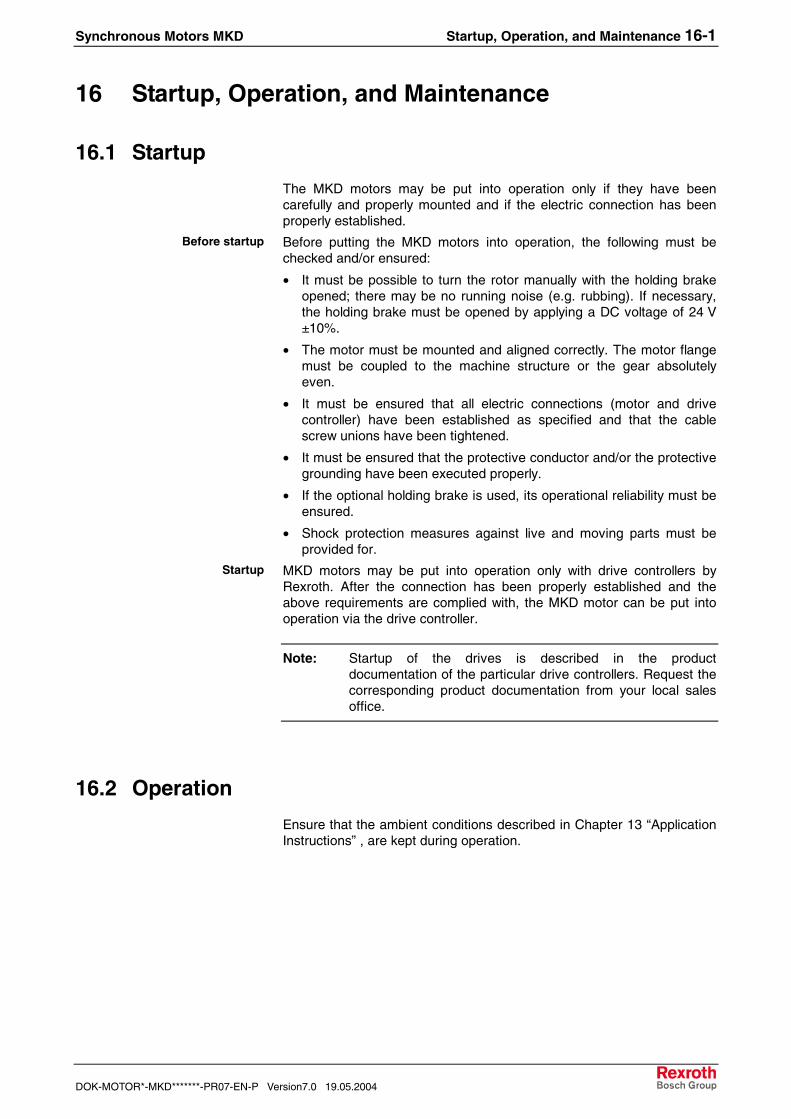
The MKD motors may be put into operation only if they have beencarefully and properly mounted and if the electric connection has beenproperly established.

Before putting the MKD motors into operation, the following must bechecked and/or ensured:

• It must be possible to turn the rotor manually with the holding brakeopened; there may be no running noise (e.g. rubbing). If necessary,the holding brake must be opened by applying a DC voltage of 24 V±10%.

• The motor must be mounted and aligned correctly. The motor flangemust be coupled to the machine structure or the gear absolutelyeven.

• It must be ensured that all electric connections (motor and drivecontroller) have been established as specified and that the cablescrew unions have been tightened.

• It must be ensured that the protective conductor and/or the protectivegrounding have been executed properly.

• If the optional holding brake is used, its operational reliability must beensured.

• Shock protection measures against live and moving parts must beprovided for.

MKD motors may be put into operation only with drive controllers byRexroth. After the connection has been properly established and theabove requirements are complied with, the MKD motor can be put intooperation via the drive controller.

Note: Startup of the drives is described in the productdocumentation of the particular drive controllers. Request thecorresponding product documentation from your local salesoffice.

16.2 Operation

Ensure that the ambient conditions described in Chapter 13 “ApplicationInstructions” , are kept during operation.

Before startup

Startup

16-2 Startup, Operation, and Maintenance Synchronous Motors MKD

19.05.2004 Version7.0 DOK-MOTOR*-MKD*******-PR07-EN-P

16.3 Maintenance

CleaningExcessive dirt, dust or shavings may affect the function of the motorsadversely, may in extreme cases even cause a failure of the motors. Forthat reason, you should clean

• the cooling ribs of the motors at regular intervals, in order to obtain asufficiently large heat radiation surface. If the cooling ribs are dirty inpart, sufficient heat dissipation via the environmental air is notpossible any longer.

An insufficient heat radiation may have undesired consequences. Thebearing service life is reduced by operation at impermissibly hightemperatures (the bearing grease is decomposing). Switchoff caused byovertemperature despite operation on the basis of selected data,because the appropriate cooling is missing.

BearingsThe nominal service life of the bearings is L10h = 30.000 h according toDIN ISO 281, ed. 1990, if the permissible radial and axial forces are notexceeded (see Chapter 16.7). Even if the bearings are loaded withhigher forces to a minor degree only, their service life is affectednegatively.

The motor bearings should be replaced if

• the nominal bearing service life has been reached,

• running noise can be heard.

Note: We recommend that bearings are replaced by the RexrothIndramat Service.

Connection CableCheck connection lines for damage at regular intervals and replacethem, if necessary.

Check any optionally present energy management chains (drag chains)for defects.

DANGER

Electrocution by live parts of more than 50 V!⇒ Do not repair any connection lines provisionally. If

the slightest defects are detected in the cablesheath, the system must be put out of operationimmediately. Then the cable must be replaced.

Check the protective conductor connection for proper state and tightseat at regular intervals and replace it, if necessary.

Cooling ribs

Synchronous Motors MKD Startup, Operation, and Maintenance 16-3

DOK-MOTOR*-MKD*******-PR07-EN-P Version7.0 19.05.2004

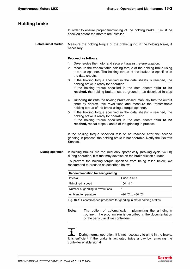
Holding brakeIn order to ensure proper functioning of the holding brake, it must bechecked before the motors are installed.

Measure the holding torque of the brake; grind in the holding brake, ifnecessary.

Proceed as follows:

1. De-energize the motor and secure it against re-energization.2. Measure the transmittable holding torque of the holding brake using

a torque spanner. The holding torque of the brakes is specified inthe data sheets.

3. If the holding torque specified in the data sheets is reached, theholding brake is ready for operation.If the holding torque specified in the data sheets fails to bereached, the holding brake must be ground in as described in step4.

4. Grinding in: With the holding brake closed, manually turn the outputshaft by approx. five revolutions and measure the transmittableholding torque of the brake using a torque spanner.

5. If the holding torque specified in the data sheets is reached, theholding brake is ready for operation.If the holding torque specified in the data sheets fails to bereached, repeat steps 4 and 5 of the grinding-in process.

If the holding torque specified fails to be reached after the secondgrinding-in process, the holding brake is not operable. Notify the RexrothService.

If holding brakes are required only sporadically (braking cycle >48 h)during operation, film rust may develop on the brake friction surface.

To prevent the holding torque specified from being fallen below, werecommend to proceed as described below:

Recommondation for seat grinding

Interval Once in 48 h

Grinding-in speed 100 min–1

Number of grinding-in revolutions 1

Ambient temperature –20 °C to +50 °C

Fig. 16-1: Recommended procedure for grinding in motor holding brakes

Note: The option of automatically implementing the grinding-inroutine in the program run is described in the documentationof the particular drive controllers.

During normal operation, it is not necessary to grind in the brake.It is sufficient if the brake is activated twice a day by removing thecontroller enable signal.

Before initial startup

During operation

16-4 Startup, Operation, and Maintenance Synchronous Motors MKD

19.05.2004 Version7.0 DOK-MOTOR*-MKD*******-PR07-EN-P

Changing the batteryDrive control systems of Rexroth observe voltage of battery safely andgive just in time a warning “change battery”.

Changing the battery should be made, when machine is under load. Thisis necessary to avoid an overrun in the motor encoder (switch off controlvoltage can cause loss of absolute values).

Following tools and spare parts are needed:• Screw driver Torx according to Fig. 16-2

• Needle-nosed pliers

• Torque spanner with setting range 1.3-6.8 Nm.

• New, assembled battery forMKD025. -041, -071. Ord. No. R911277133MKD090, -112 Ord. No. R911281394

housing-screw thread Screw driver size Starting torque

MKD025, -041 M3 Torx T 10 1.4 Nm

MKD071, -090, -112: M4 Torx T 20 3.0 Nm

Fig. 16-2: Overview housing-screws

DANGER

Danger to life by electric voltage!To change the battery you must work when machine is

under load. Therefore:

⇒ Any work required on the electric system may onlybe carried out by skilled electricians.

⇒ Switch off power supply at the drive control systemsand save against re-start!

DANGER

Hazardous movements!Danger to life, mayhem or material damage!⇒ Switch off power supply at the drive control systems

and save against re-start!⇒ Change battery on drive control systems only when

control voltage is inserted. Is the control voltageswitched off when the battery is removed, theabsolute value is lost and when the machine will beswitched on, a failing movement could be possible.

1. Loosen housing screws (1) with a torx-screw driver (appropriate sizesee Fig. 16-2).

2. Dismount housing lid.3. Take off the connector of the battery (2).4. Lossen screws (3) of the battery`s screw terminal and remove the

battery.

Change battery when machine isunder load

Change battery

Remove the battery

Synchronous Motors MKD Startup, Operation, and Maintenance 16-5

DOK-MOTOR*-MKD*******-PR07-EN-P Version7.0 19.05.2004

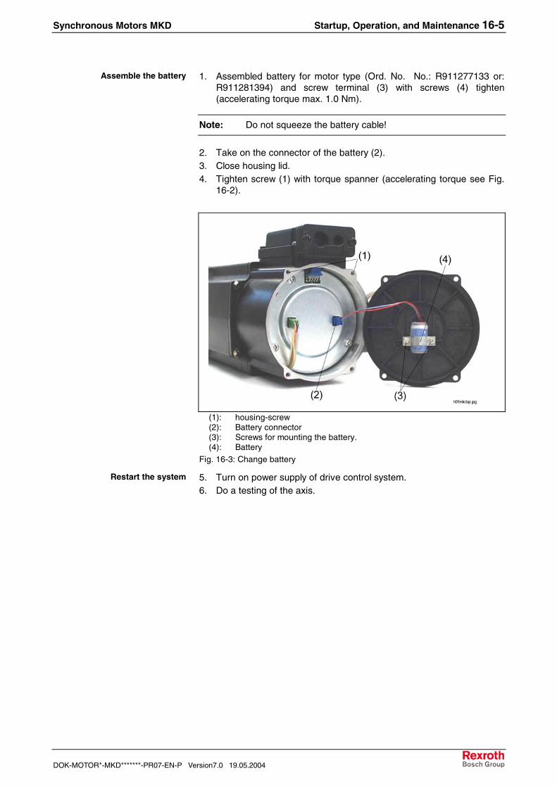
1. Assembled battery for motor type (Ord. No. No.: R911277133 or:R911281394) and screw terminal (3) with screws (4) tighten(accelerating torque max. 1.0 Nm).

Note: Do not squeeze the battery cable!

2. Take on the connector of the battery (2).3. Close housing lid.4. Tighten screw (1) with torque spanner (accelerating torque see Fig.

16-2).

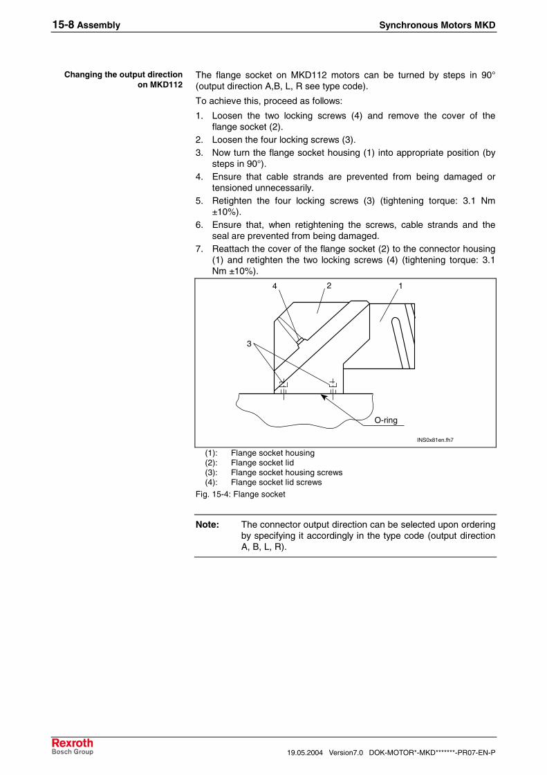
(1): housing-screw(2): Battery connector(3): Screws for mounting the battery.(4): Battery

Fig. 16-3: Change battery

5. Turn on power supply of drive control system.6. Do a testing of the axis.

Assemble the battery

Restart the system

16-6 Startup, Operation, and Maintenance Synchronous Motors MKD

19.05.2004 Version7.0 DOK-MOTOR*-MKD*******-PR07-EN-P

Synchronous Motors MKD Appendix 17-1

DOK-MOTOR*-MKD*******-PR07-EN-P Version7.0 19.05.2004

17 Appendix

17-2 Appendix Synchronous Motors MKD

19.05.2004 Version7.0 DOK-MOTOR*-MKD*******-PR07-EN-P

17.1 List of Standards

Standard Edition Title Concordance

89/392/EECreplaced by98/37/EG

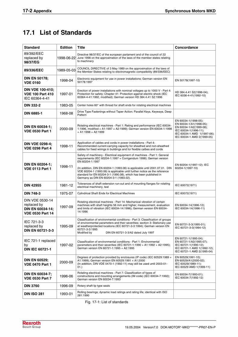
1998-06-22Directive 98/37/EC of the european parlament and of the council of 22June 1998 on the approximation of the laws of the member states relatingto machinery

89/336/EEC 1989-05-03 COUNCIL DIRECTIVE of 3 May 1989 on the approximation of the laws ofthe Member States relating to electromagnetic compatibility (89/336/EEC)

DIN EN 50178;VDE 0160

1998-04 Electronic equipment for use in power installations; German version EN50178:1997

EN 50178(1997-10)

DIN VDE 100-410;VDE 100 Part 410IEC 60364-4-41

1997-01Erection of power installations with nominal voltages up to 1000 V - Part 4:Protection for safety; Chapter 41: Protection against electric shock (IEC60364-4-41:1992, modified); German version HD 384.4.41 S2:1996

HD 384.4.41 S2(1996-04);IEC 6036-4-41(1992-10)

DIN 332-2 1983-05 Center holes 60° with thread for shaft ends for rotating electrical machines

DIN 6885-1 1968-08 Drive Type Fastenings without Taper Action; Parallel Keys, Keyways, DeepPattern

DIN EN 60034-1;VDE 0530 Part 1

2000-09Rotating electrical machines - Part 1: Rating and performance (IEC 60034-1:1996, modified + A1:1997 + A2:1999); German version EN 60034-1:1998+ A1:1998 + A2:1999

EN 60034-1(1998-05);EN 60034-1/A1(1998-05);EN 60034-1/A2(1999-08);IEC 60034-1(1996-11);IEC 60034-1 AMD 1(1997-06);IEC 60034-1 AMD 2(1999-05)

DIN VDE 0298-4;VDE 0298 Part 4

1998-11Application of cables and cords in power installations - Part 4:Recommended current-carrying capacity for sheathed and non-sheathedcables for fixed wirings in buildings and for flexible calbes and cords

DIN EN 60204-1;VDE 0113 Part 1

1998-11

Safety of machinery - Electrical equipment of machines - Part 1: Generalrequirements (IEC 60204-1:1997 + Corrigendum 1998); German versionEN 60204-1:1997

(In addition, DIN EN 60204-1 (1993.06) is applicable until 2001.07.01. DINVDE 60204-1 (1993.06) is applicable until further notice as the referencestandard for EN 60204-3-1 (1990.08), which has been published inGermany as DIN EN 60204-3-1 (1993.02).

EN 60204-1(1997-12); IEC60204-1(1997-10)

DIN 42955 1981-12 Tolerances of shaft extension run-out and of mounting flanges for rotatingelectrical machinery, test

IEC 60072(1971)

DIN 748-3 1975-07 Cylindrical Shaft Ends for Electrical Machines IEC 60072(1971)

DIN VDE 0530-14replaced byDIN EN 60034-14;VDE 0530 Part 14

1997-09Rotating electrical machines - Part 14: Mechanical vibration of certainmachines with shaft heights 56 mm and higher; measurement, evaluationand limits of vibration (IEC 60034-14:1996); German version EN 60034-14:1996

EN 60034-14(1996-12);IEC 60034-14(1996-11)

IEC 721-3-3replaced byDIN EN 60721-3-3

1995-09

Classification of environmental conditions - Part 3: Classification of groupsof environmental parameters and their severities; section 3: Stationary useat weatherprotected locations (IEC 60721-3-3:1994); German version EN60721-3-3:1995Modified by DIN EN 60721-3-3/A2 dated July 1997

EN 60721-3-3(1995-01);IEC 60721-3-3(1994-12)

IEC 721-1 replacedbyDIN IEC 60721-1

1997-02Classification of environmental conditions - Part 1: Environmentalparameters and their severities (IEC 60721-1:1990 + A1:1992 + A2:1995);German version EN 60721-1:1995 + A2:1995

EN 60721-1(1995-04);EN 60721-1/A2(1995-07);IEC 60721-1(1990-12);IEC 60721-1 AMD 1(1992-12);IEC 60721-1 AMD 2(1995-04)

DIN EN 60529;VDE 0470 Part 1

2000-09Degrees of protection provided by enclosures (IP code) (IEC 60529:1989 +A1:1999); German version EN 60529:1991 + A1:2000(In addition, DIN VDE 0470-1 (1992-11) may still be used until 2003-01-01.)

EN 60529(1991-10);EN 60529/A1(2000-02);IEC 60529(1989-11);IEC 60529 AMD 1(1999-11)

DIN EN 60034-7;VDE 0530 Part 7

1996-06Rotating electrical machines - Part 7: Classification of types ofconstructions and mounting arrangements (IM code) (IEC 60034-7:1992);German version EN 60034-7:1993

EN 60034-7(1993-01);IEC 60034-7(1992-12)

DIN 3760 1996-09 Rotary shaft lip type seals

DIN ISO 281 1993-01 Rolling bearings; dynamic load ratings and rating life; identical with ISO281:1990

Fig. 17-1: List of standards

Synchronous Motors MKD Appendix 17-3

DOK-MOTOR*-MKD*******-PR07-EN-P Version7.0 19.05.2004

17.2 Selecting Power Cables

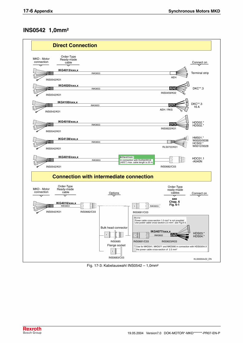
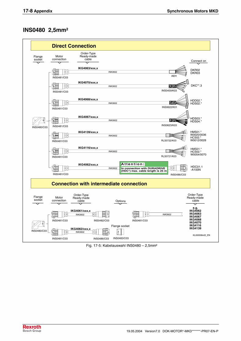
The tables and diagrams shown on the following pages are intended tosupport you in selecting the power cables required. The example belowexplains how to proceed.

A power cable set, 5.0 m in length, is needed for a MKD112A-024motor, Natural 60K operating mode, and an HDS02. drive controller.

Proceed as follows:

1. Select the motor and the operating mode in the cable selection table.2. “X” identifies the connection cross-section required.3. Read the size of the power connector and the connection cross-

section from the table header.4. On the following pages, select the corresponding selection diagram

by connector size and connection cross-section.5. Select the required power cable set in the diagram. Complete the

selected ordering type IKGxxxx/xxx.x by the desired length.In the example above, the ordering type IKG4055/xxx.x is taken from theselection diagram. For ordering, complete the ordering type by thedesired length.

Ordering type: IKG4055/005,0

$1���))����0 ����2�������!�3����!�34

�����������*����"��!

3�����34 ���()��"���������

/-�,�',5

5,�

�6

/-�,���5

5,�

�6

/-�,�',5

5��

�6

/-�,�',5

�5��

�6

������ ���3+�� �����3+�� ���

������ ���3+�� �����3+�� ���

��;���� ���3+�� �����3+�� ���

��;�� ���3+�� �����3+�� ���

������� ���3+�� �����3+�� ���&3+,�/�

�������� ���3+�� �����3+�� ���63+,�/� ��B���

�������� ���3+�� �����3+�� ���63+,�/� ��B���

Connection toHDSX3.XHDSX4.X

Note:Power cablecross section1,5 mm² is not

possible!

Use cableswith 2,5 mm²cross-section!

seeFig. 4.3

$1�

/-�,�',� 5���6

&���/�C���/�.C�#�,%�

��))����0 ����2�������!�3����!�34

;��� ���3+�� �����3+�� ���63+,�/� ��B���

;���� ���3+�� �����3+�� ���63+,�/� ��B���

DDDDDDDDDDDDDDDDD

DDDD

DD

Motorflangesocket

Motorconnection

Connection toHDDX2.XHDSX2.X

INK0650IKG4055/xxx,x

INS0481/C02

Connection toDKCXX.3

INK0650IKG4060/xxx,x

INS0481/C02

INS0622/K01

4321

7654321

INS0459/K02

4321

INK0650IKG4053/xxx,x

INS0481/C02

Connection toterminal strip

Y05VZD1A.fh7

z. B.IKG4053IKG4055

Direct connection

Intermediate connection

INS0481/C02

INK0650

Flange socket

INS0483/C02

INS0481/C02

INK0650

IKG4051/xxx,x

INS0482/C02

INK0650IKG4052/xxx,x

INS0486/C02

Coupling

INS0480/C02

INS0481/C02

INS0480/C02

Motorflangesocket

Motorconnection

Ordering-typeready made cable

AEH

Options

IKG4067/xxx,x

INS0481/C02 INS0623/K03

INK0602

7654321

Ordering-typeready made cable

Ordering-typeready made cable

(1): Select motor type and operating mode.(2), (3) : Read the connector size and the cross-section off the column

header.(4): Consult the corresponding diagram.(5): Select the desired cable.

Fig. 17-2: Instructions on how to select a cable

Example

17-4 Appendix Synchronous Motors MKD

19.05.2004 Version7.0 DOK-MOTOR*-MKD*******-PR07-EN-P

Motor MKD Mode ofoperationt

INS

0680

,1,

0mm

²

INS

0542

,1,

0 m

INS

0480

,1,

5mm

²

INS

0480

,2,

5mm

²

INS

0480

,4,

0mm

²

INS

0480

,6,

0mm

²

INS

0480

,10

,0m

INS

0380

,6,

0mm

²

INS

0380

,10

,0m

INS

0380

,16

,0m

025A-144 Natural 60K XStecker Natural 100K X025A-144 Natural 60K Xtermial box Natural 100K X025B-058 Natural 60K XStecker Natural 100K X025B-058 Natural 60K Xtermial box Natural 100K X025B-144 Natural 60K XStecker Natural 100K X025B-144 Natural 60K Xtermial box Natural 100K X041B-143 Natural 60K X

Natural 100K X041B-144 Natural 60K X

Natural 100K X071B-024 Natural 60K X

Natural 100K XSurface X

071B-035 Natural 60K XNatural 100K XSurface X

071B-061 Natural 60K XNatural 100K XSurface X

090B-035 Natural 60K XNatural 100K XSurface X

090B-046 Natural 60K XNatural 100K XSurface 60K/100K X

090B-047 Natural 60K XNatural 100K XSurface 60K/100K X

090B-058 Natural 60K XNatural 100K XSurface 60K/100K X

112A-024 Natural 60K XNatural 100K XSurface 60K/100K X

112A-058 Natural 60K XNatural 100K XSurface 60K/100K X

112B-024 Natural 60K XNatural 100K XSurface 60K/100K X

112B-048 Natural 60K XNatural 100K XSurface 60K/100K X

112B-058 Natural 60K XNatural 100K XSurface 60K/100K X

112C-024 Natural 60K XNatural 100K XSurface 60K/100K X

112C-058 Natural 60K XNatural 100K XSurface 60K/100K X

112D-027 Natural 60K XNatural 100K XSurface 60K/100K X

Fig. 17-1: Overview of power connector cross-section

Synchronous Motors MKD Appendix 17-5

DOK-MOTOR*-MKD*******-PR07-EN-P Version7.0 19.05.2004

INS0680 1,0mm²

7���� �5���4

6�*�"�'&% ��'"���5��'�+��� ��,,@�+������.���+% �AB���.�*�"�'&% ��'"���5��'�+���� ��,,@�����<+� �5�

�� �� 4

7�1�� C7�1�� C

��

�;7�D���1

���

���

< &�����'(��

����"'����'�+��

7���� C7�1�� C34�����

341����D���

341����D��� 341����D���

34�����5�6�� 788898

341����D���

341����

���CC �34�����

341����D���

341����D���

��"�5�6�� 5�6��,5�6��05�6���5�6���5�6�005�6��0

341����D���

����

�������

�- (���&$�'����'��"

341����D���

����

34�����

341����D���

8�",+�& ���"+.

��������!��E$�

�������:���������

341����D���

34�����

< &������'(��

341����D���

< &������'(��

����"'����'�+��

F"$�"582.���&$25,&$��'&% �

F"$�"582.���&$25,&$��'&% �

F"$�"582.���&$25,&$��'&% �

;7

F.�+���

341����D��� 341����D���

34�����

�������

�����'����

5�6���788898

5�6��0788898

5�6��,788898

5�6���788898

341����D���

34�����5�6�� 788898

341����D���

34�����

341����D���

5�6�00788898���CC �

���

:����������/��#����������'�������������

5�������������/��#��;<=�<5>3�)�:?���'8���'*!��!��"�#����%���

= � � �� � � �� 4

34�����

341����D���

5�6��0788898�

7�1�� C?����D����7�1�� C?����D������1����D���

Fig. 17-2: Kabelauswahl INS0680 – 1,0mm²

17-6 Appendix Synchronous Motors MKD

19.05.2004 Version7.0 DOK-MOTOR*-MKD*******-PR07-EN-P

INS0542 1,0mm²

34�����5�6��,788898

341����D���

34�����5�6�� 788898

341����D���

34�����5�6��788898

���:#'.�� @�"�� ��

34�����5�6�� 788898

341����D���

��������!��E;4

B�G�?�

8�8��"H�"5

B�G�?�

8�8��"H�"5

B�G�?�

8�8��"H�"5

����5�����"'����'�+��

B�G�?�

8�8��"H�"5

341����D���

341����D���

341����

�- (���&$�'����'��"

341����D���

34�����

< &������'(��

341����D���

����5�����"'����'�+��

F"$�"582.���&$25,&$�

�'&% �

F"$�"582.�"�&$25,&$�

'&% ��F.�+���

F"$�"582.���&$25,&$�

'&% �

5�6���788898

341����D��� 341����D���

34�����

������� 7�1�� C

7�1�� C

�0

7���� C7�1�� C

���CC �

341����D���

����

�������

341����D���

����

8�",+�& ���"+.;7

�����'����

341����D���

34�����5�6�� 788898

B�G�?�

8�8��"H�"5

341����D���

�����'����

B���#�"����������������&�$��������+��'����'�+���*+���7�1��D�� I����.�*�"�'&% ��'"���5��'�+����#��� ��,,@

3��'����'�+���*+����B���3G;/7��C0�,&9 �'&% �� ������+�����,

=� � �� � � �� 4

34�����5�6���788898

B�G�?�

8�8��"H�"5

341����D���

���CC ����

�������:���������

:����������/��#����������'�������������

34�����5�6� ,788898

B�G�?�

8�8��"H�"5

341����D���

��

��1����D���

7�1�� C?����D����7�1�� C?����D����

� ) � � �

7���� �5���4

��

�;7�D���1

���

���

6�*�"�'&% ��'"���5��'�+���� ��,,@�+������.���+% �AB���.�*�"�'&% ��'"���5��'�+���� ��,,@������<+� �5�

Fig. 17-3: Kabelauswahl INS0542 – 1,0mm²

Synchronous Motors MKD Appendix 17-7

DOK-MOTOR*-MKD*******-PR07-EN-P Version7.0 19.05.2004

INS0480 1,5mm²

7���� �5���4

7�1�� C7�1�� C

6�*�"�'&% ��'"���5��'�+��� ��,,@�+������.���+% �AB���.�*�"�'&% ��'"���5��'�+���� ��,,@�����<+� �5�

�� �� 4

< &�����'(��

����"'����'�+��

34�����

5�6�%%788898

341����D���

34�����

5�6� �788898

341����D���

34�����

5�6�% 788898

341����D���

��������!��E;4

��"�5�6�%5�6�% 5�6�%%5�6� �5�6��%5�6��

341����D���

34�����

< &������'(��

341����D���

341����D���

34�����

5�6�%�788898

341����D���

34�����5�6�%788898

341����D���

341����D���

341����D���

341����D���

< &�����'(��

����"'����'�+��

F"$�"582.���&$25,&$�

'&% �

F"$�"582.���&$25,&$�

'&% �

F"$�"582.���&$25,&$�

'&% �

F.�+���

5�6� �788898

341����D���

34�����

341����D���

����

�������

341����D���

����

����������

;7

341����D���

�������

�����'����

341����D��� 341����D���

5�6�%78889834�����

�������:���������

7���� C7�1�� C

���CC �

:����������/��#����������'�������������

5�������������/��#��;<=�<5>3�)�:?���'8���'*!��!��"�#�%��

= � � �� � � �� 4

34�����

5�6��788898�

��1����D���

��1����D���

341����D���

34�����

5�6��%788898�

341����D���

7�1�� C?����D����7�1�� C?����D����

7�1�� C7�1�� C?����D����

Fig. 17-4: Kabelauswahl INS0480 – 1,5mm²

17-8 Appendix Synchronous Motors MKD

19.05.2004 Version7.0 DOK-MOTOR*-MKD*******-PR07-EN-P

INS0480 2,5mm²

7���� �5���4

7�1�� C7�1�� C

< &�����'(��

����"'����'�+��

34�����

5�6� ,788898

341����D���

34�����

5�6���788898

341����D���

34�����

5�6� 788898

341����D���

��������!��E;4

��"�5�6� 5�6� 5�6� �5�6� ,5�6���5�6�� 5�6� 0

< &�����'(��

����"'����'�+��

F"$�"582.���&$25,&$�

�'&% �

F"$�"582.���&$25,&$�

'&% �

F"$�"582.���&$25,&$�

'&% �

F.�+���

5�6� �788898

341����D���

34�����

341����D���

����

�������

341����D���

����

����������

;7

341����D���

�������

�����'����

341����D��� 341����D���

5�6� 78889834�����

�������:���������

7���� C7�1�� C

���CC �

:����������/��#����������'�������������

5�������������/��#��;<=�<5>3�)�:?���'8���'*!��!��"�#����%��

= � � �� � � �� 4

34�����

5�6� 0788898�

��1����D���

��1����D���

341����D���

34�����

5�6�� 788898�

341����D���

341����D���

34�����

< &������'(��

341����D���

341����D���

34�����

5�6� �788898

341����D���

34�����5�6� 788898

341����D���341����D���

341����D���

341����D���

7�1�� C?����D����7�1�� C?����D����

7�1�� C7�1�� C?����D����

Fig. 17-5: Kabelauswahl INS0480 – 2,5mm²

Synchronous Motors MKD Appendix 17-9

DOK-MOTOR*-MKD*******-PR07-EN-P Version7.0 19.05.2004

INS0480 4,0mm²

7���� �5���4

7�1�� C7�1�� C

< &�����'(��

����"'����'�+��

34�����

5�6�0�788898

341����D���

34�����

5�6�, 788898

341����D���

��������!��E;4

�����5�6�,�5�6�,5�6�, 5�6�,�5�6�0�5�6���5�6���

341����D���

34�����

< &������'(��

341����D���

341����D���

34�����

5�6�,�788898

341����D���

34�����5�6�,788898

341����D���

341����D���

341����D���

341����D���

< &�����'(��

����"'����'�+��

F"$�"582.���&$25,&$�

'&% �F"$�"582.�

��&$25,&$��'&% �

F"$�"582.���&$25,&$��'&% �

F.�+���

5�6�,�788898

341����D���

34�����

341����D���

����

����������

;7

341����D���

�������

�����'����

341����D��� 341����D���

5�6�,78889834�����

�������:���������

���CC �

:����������/��#����������'�������������

5�������������/��#����'���&��)�:?���'8���'*!��!��"�#����%��

= � � �� � � ��

34�����

5�6���788898�

��1����D���

��1����D���

341����D���

34�����

5�6���788898�

341����D���

7�1�� C?����D����7�1�� C?����D����

7�1�� C7�1�� C?����D����

Fig. 17-6: Kabelauswahl INS0480 – 4,0mm²

17-10 Appendix Synchronous Motors MKD

19.05.2004 Version7.0 DOK-MOTOR*-MKD*******-PR07-EN-P

INS0480 6,0mm²

7���� �5���4

7�1�� C7�1�� C

< &�����'(��

����"'����'�+��

34�����

5�6�%�788898

341����D���

34�����

5�6� 788898

341����D���

��������!��E;4

�����5�6��5�6�5�6� 5�6��5�6�%�5�6� 5�6888

341����D���

34�����

< &������'(��

341����D���

341����D���

34�����

5�6��788898

341����D���

34�����5�6�788898

341����D���

341����D���

341����D���

341����D���

< &�����'(��

����"'����'�+��

F"$�"582.���&$25,&$�

'&% �

F"$�"5�2.���&$25,&$�

'&% �

F"$�"582.���&$25,&$�

'&% �

F.�+���

5�6��788898

341����D���

34�����

341����D���

����

�����

;7

341����D���

�������

�����'����

341����D��� 341����D���

5�6�78889834�����

�������:���������

���CC �

:����������/��#����������'�������������

5�������������/��#����'���&��)�:?���'8���'*!��!��"�#����%��

= � � �� � � �� 4

34�����

5�6� 788898�

��1����D���

��1����D���

341����D���

34�����

5�6�%%788898

341����D���

����

7�1�� C7�1�� C?����D����

7�1�� C?����D����7�1�� C?����D����D����������������

Fig. 17-7: Kabelauswahl INS0480 – 6,0mm²

Synchronous Motors MKD Appendix 17-11

DOK-MOTOR*-MKD*******-PR07-EN-P Version7.0 19.05.2004

INS0480 10,0mm²

7���� �5���4

7�1�� C7�1�� C

< &������'(��

����"'����'�+��

34�����

5�6� �788898

341����D���

34�����

5�6� 788898

341����D���

��������!��E;4

��"�5�6��5�6�5�6� 5�6��5�6� �5�6� 05�6��%

341����D���

34�����

< &������'(��

341����D���

341����D���

34�����

5�6��788898

341����D���

34�����5�6�788898

341����D���

341����D���

341����D���

341����D���

< &�����'(��

����"'����'�+��

F"$�"582.���&$25,&$��'&% �

F"$�"582.���&$25,&$��'&% �

F"$�"582.���&$25,&$��'&% �

F.�+���

5�6��788898

341����D���

34�����

341����D���

����

�����

;7

341����D���

�������

�����'����

341����D��� 341����D���

5�6�78889834�����

�������:���������

���CC �

:����������/��#����������'�������������

5�������������/��#����'���&��)�:?���'8���'*!��!��"�#����%��

= � � �� � � �� 4

34�����

5�6��%788898�

��1����D���

��1����D���

341����D���

34�����

5�6� 0788898

341����D���

����

7�1�� C7�1�� C?����D����

7�1�� C?����D����7�1�� C?����D����D����������������

Fig. 17-8: Kabelauswahl INS0480 – 10,0mm²

17-12 Appendix Synchronous Motors MKD

19.05.2004 Version7.0 DOK-MOTOR*-MKD*******-PR07-EN-P

INS0380 6,0mm²

7���� �5���4

7�1�� C7�1�� C

< &�����'(��

����"'����'�+��

34�����

5�6�%�788898

341����D���

34�����

5�6� 788898

341����D���

��������!��E;4

�����5�6��5�6�5�6� 5�6��5�6�%�5�6� 5�6888

341����D���

34�����

< &������'(��

341����D���

341����D���

34�����

5�6��788898

341����D���

34�����5�6�788898

341����D���

341����D���

341����D���

341����D���

< &�����'(��

����"'����'�+��

F"$�"582.���&$25,&$�

'&% �

F"$�"5�2.���&$25,&$�

'&% �

F"$�"582.���&$25,&$�

'&% �

F.�+���

5�6��788898

341����D���

34�����

341����D���

����

�����

;7

341����D���

�������

�����'����

341����D��� 341����D���

5�6�78889834�����

�������:���������

���CC �

:����������/��#����������'�������������

5�������������/��#����'���&��)�:?���'8���'*!��!��"�#����%��

= � � �� � � �� 4

34�����

5�6� 788898�

��1����D���

��1����D���

341����D���

34�����

5�6�%%788898

341����D���

����

7�1�� C7�1�� C?����D����

7�1�� C?����D����7�1�� C?����D����D����������������

Fig. 17-9: Kabelauswahl INS0380 – 6,0mm²

Synchronous Motors MKD Appendix 17-13

DOK-MOTOR*-MKD*******-PR07-EN-P Version7.0 19.05.2004

INS0380 10,0mm²

7���� �5���4

7�1�� C7�1�� C

< &�����'(��

����"'����'�+��

34�����

5�6���788898

341����D���

34�����

5�6� 788898

341����D���

��������!��E;4

��"�5�6� �5�6� 5�6� 5�6� �5�6���5�6� ,5�6��

341����D���

34�����

< &������'(��

341����D���

341����D���

34�����

5�6� �788898

341����D���

34�����5�6� 788898

341����D���

341����D���

341����D���

341����D���

< &�����'(��

����"'����'�+��

F"$�"582.���&$25,&$�

'&% �

F"$�"582.���&$25,&$�

'&% �

F"$�"582.���&$25,&$�

'&% �

F.�+���

5�6� �788898

341����D���

34�����

341����D���

����

�����

;7

341����D���

�������

�����'����

341����D��� 341����D���

5�6� 78889834�����

�����������������

���CC �

:����������/��#����������'�������������

5�������������/��#����'���&��)�:?���'8���'*!��!��"�#����%��

= � � �� � � �� 4

34�����

5�6�� 788898�

��1����D���

��1����D���

341����D���

34�����

5�6� ,788898

341����D���

����

7�1�� C7�1�� C?����D����

7�1�� C?����D����7�1�� C?����D����D����������������

Fig. 17-10: Kabelauswahl INS0380 – 10,0mm²

17-14 Appendix Synchronous Motors MKD

19.05.2004 Version7.0 DOK-MOTOR*-MKD*******-PR07-EN-P

INS0380 16,0mm²

7���� �5���4

7�1�� C7�1�� C7�1�� C

< &�����'(��

����"'����'�+��

34�����

5�6��788898

341����D���

34�����

5�6�, 788898

341����D���

��������!��E;4

��"�5�6�,�5�6�,5�6�, 5�6�, 5�6��5�6��05�6��5�6�

341����D���

34�����

< &������'(��

341����D���

341����D���

34�����

5�6�,�788898

341����D���

34�����5�6�,788898

341����D���

341����D���

341����D���

341����D���

< &�����'(��

����"'����'�+��

F"$�"582.���&$25,&$�

'&% �

F"$�"582.�"�&$25,&$�

'&% �

F"$�"582.���&$25,&$�

'&% �

F.�+���

5�6�, 788898

341����D���

34�����

341����D���

����

�����

;7

341����D���

�������

�����'����

341����D��� 341����D���

5�6�,78889834�����

�����������������

���CC �

:����������/��#����������'�������������

5�������������/��#����'���&��)�:?���'8���'*!��!��"�#����%��

= � � �� � � �� 4

34�����

5�6��0788898�

��1����D���

��1����D���

341����D���

34�����

5�6��788898

341����D���

����

34�����

5�6� 788898

341����D���

�����

;7

7�1�� C7�1�� C?����D����

7�1�� C?����D����7�1�� C?����D����D����������������

Fig. 17-11: Kabelauswahl INS0380 – 16,0mm²

Synchronous Motors MKD Appendix 17-15

DOK-MOTOR*-MKD*******-PR07-EN-P Version7.0 19.05.2004

17.3 Selecting Encoder Cables

Different encoder cables are available for MKD Motors. The tables andgraphics represented on the following sides serve for the choice ofencoder cables.

Motor Encoder CableConnector box

Encoder CableConnector (straight)

Encoder CableConnector (angled)

Encoder Cable forREFUDRIVE

MKD025*-***-***-KN see Fig. 17-13 --- --- see Fig. 17-16

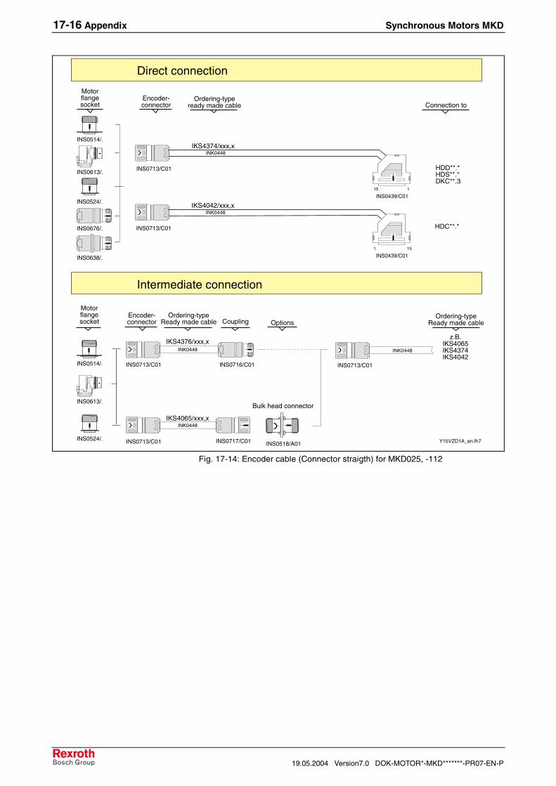
MKD025*-***-***-UN --- see Fig. 17-14 see Fig. 17-15 see Fig. 17-16

MKD041 see Fig. 17-13 --- --- see Fig. 17-16

MKD071 see Fig. 17-13 --- --- see Fig. 17-16

MKD090 see Fig. 17-13 --- --- see Fig. 17-16

MKD112 --- see Fig. 17-14 see Fig. 17-15 see Fig. 17-16

Fig. 17-12: Selecting Encoder Cables

Encoder-connection

HDD**.*HDS**.*DKC**.3

INK0448

IKS4103/xxx,x

Direct connection

Intermediate connection

INK0448

INS0518/A01

INK0448

IKS4153/xxx,x

INK0448IKS4151/xxx,x

Bulk head connector

INS0716/C01 INS0713/C01

INS0672/C01

INS0672/C01

INS0672/C01 Y17VZD1A_en.fh7

CouplingOrdering-type

Ready made cable Selection

Ordering-typeReady made cable

Encoder-connection

seeencoder cablein straight design

Options

INK0448

IKS4043/xxx,x

INS0672/C01

115INS0439/C01

HDC**.*

151INS0439/C01

INS0717/C01

Connection to

Fig. 17-13: Encoder cable for MKD025, -041, -071, -090 with Connector box

17-16 Appendix Synchronous Motors MKD

19.05.2004 Version7.0 DOK-MOTOR*-MKD*******-PR07-EN-P

INK0448IKS4042/xxx,x

z.B.IKS4065IKS4374IKS4042

Direct connection

Intermediate connection

INK0448

INS0518/A01

INK0448

IKS4376/xxx,x

INK0448IKS4065/xxx,x

INS0713/C01

Bulk head connector

INS0716/C01 INS0713/C01

INS0514/.

INS0713/C01

INS0713/C01 Y15VZD1A_en.fh7

Coupling

Motorflangesocket

Ordering-typeReady made cable

Ordering-typeReady made cable

Ordering-typeready made cable

Encoder-connector

Motorflangesocket

INS0613/.

INS0514/.

INS0613/.

INS0717/C01

INS0524/.

Encoder-connector

INS0524/.

Options

INS0676/.

INS0638/.

151

INS0439/C01

HDC**.*

INK0448IKS4374/xxx,x

INS0713/C01

115

INS0439/C01

HDD**.*HDS**.*DKC**.3

Connection to

Fig. 17-14: Encoder cable (Connector straigth) for MKD025, -112

Synchronous Motors MKD Appendix 17-17

DOK-MOTOR*-MKD*******-PR07-EN-P Version7.0 19.05.2004

Encoder-connector

Direkte Verbindung

Intermediate connection

Coupling

Motorflangesocket

Ordering-typeReady made cabel selection

Encoder-connector

Ordering-typeReady made cable

Motorflangesocket

INK0448IKS4375/xxx,x

INS0514/.

INS0613/.

INS0524/.

INS0511/C01

seeencoder cablein straight design

INK0448

INS0518/A01

INK0448

IKS4377/xxx,x

INK0448

IKS4066/xxx,x

Bulk head connector

INS0716/C01 INS0713/C01

INS0511/C01

INS0511/C01Y16VZD1A_en.fh7

INS0514/.

INS0613/.

INS0717/C01INS0524/.

Options

151

INS0439/C01

HDC**.*

115

INS0439/C01

HDD**.*HDS**.*DKC**.3

INK0448IKS4044/xxx,x

INS0511/C01

Connection to

Fig. 17-15: Encoder cable (Connector angled) for MKD025, -112

Encoder-connection

RD52

INK0690

IKS5004/xxx,x

Direct connection

INS0672/C01

G01Refu_en.fh7

Ordering-typeReady made cable

INS0713/C01

126INS0695/C01

RD52

Connection to

INK0690

IKS5003/xxx,x

126INS0695/C01

Fig. 17-16: Encoder cable MKD - REFUDRIVE RD52

17-18 Appendix Synchronous Motors MKD

19.05.2004 Version7.0 DOK-MOTOR*-MKD*******-PR07-EN-P

Synchronous Motors MKD Index 18-1

DOK-MOTOR*-MKD*******-PR07-EN-P Version7.0 19.05.2004

18 Index

AAmbient Temperature 13-1

BBalance 4-3Bar code label 14-1Battery

assembling 16-5changing 16-4removing 16-4

BlowerNotes on ordering 13-7

CCable sets 14-2Centering diameter 4-2Characteristic motor speed 5-3Characteristic voltage limit curves 5-5commutation 1-1Commutation 1-3Connecting the motor

with connection box 15-4with plug-in connectors 15-6

Connection Cable 16-2Connection diagram

Motor with connector box 12-2motors with connector receptacle 12-4overview 12-1

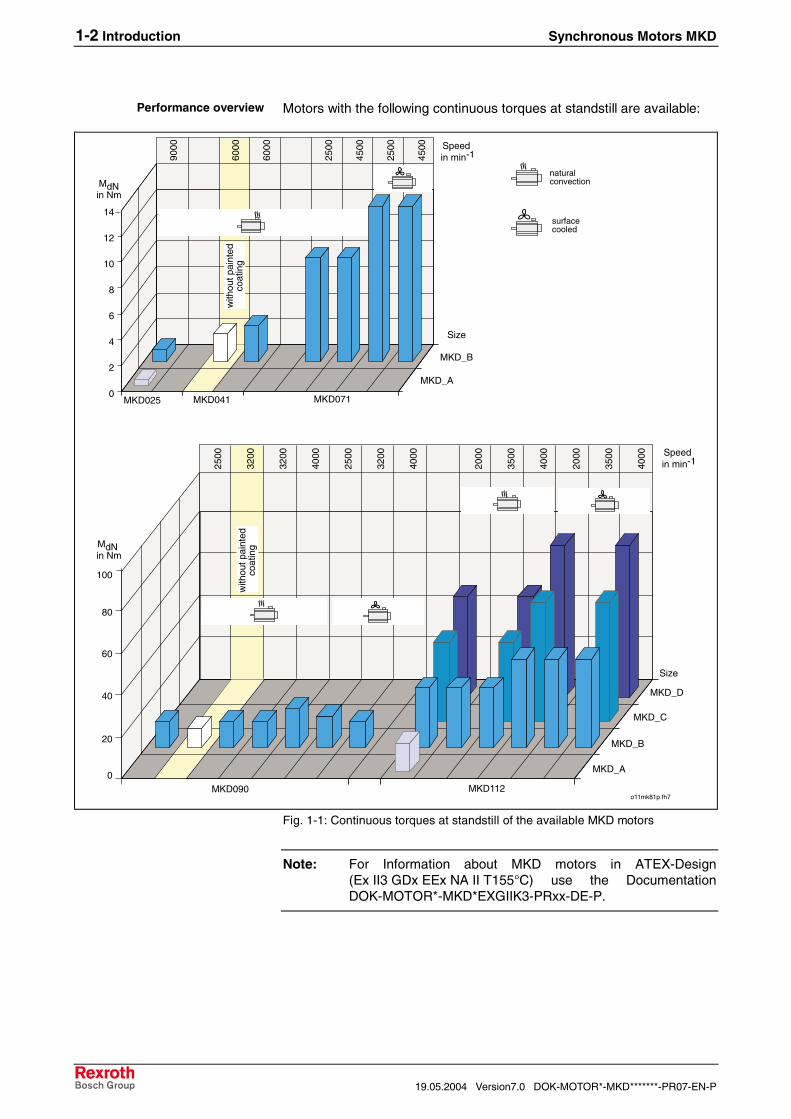
Connection diagram blower type (1) 12-6Continuous current at standstill 5-3Continuous torque at standstill 1-2, 5-3continuous torques at standstill 1-2Cooling ribs 16-2Cycle duration 5-2Cyclic duration factor 5-2

DDegree of protection 13-3Delivery note 14-1Designs 1-3Drag chains 16-2Dynamics 1-1

EEncoder connector 15-6Encoder data memory 13-13Encoder system 4-3Energy management chains 16-2

FFields of application 1-1Flange size 4-2

GGearings 11-2

18-2 Index Synchronous Motors MKD

19.05.2004 Version7.0 DOK-MOTOR*-MKD*******-PR07-EN-P

HHeat dissipation 16-2Holding brake 4-3

grind in 16-3principle 13-8safety note 13-8startup 16-3wear and tear 13-8

Housing overtemperature 5-1

IIdentification 14-1Idle time 5-2Intended use

Fields of application 2-2Introduction 2-1Requirements 2-1

KKey 13-9

LLifting sling belts 14-3Locking screws 15-2

MMachine accuracy 5-1Maintenance-free operation 1-1Mass 5-4Maximum speed 5-4Moment of inertia of the rotor 5-4Motor

Design and components 1-3Motor feedback

encoder data memory 13-13Motor feedback (Encoder system) 4-2Motor frame length 4-2Motor frame size 4-2Motor overtemperature

100-K 5-160-K 5-1

Motor versionsMounting position 13-6

NNon-intended use 2-2

Consequences, disclaimer of liability 2-1Number of pole pairs 5-3

OON time 5-2Operating modes 5-2Operation Curve

S1 5-5S6 5-5

Operational reliability 1-1Order types of the sealing air connectors 11-1Other performances 4-4Output direction 4-4Output Direction of Power Connector 4-4

Synchronous Motors MKD Index 18-3

DOK-MOTOR*-MKD*******-PR07-EN-P Version7.0 19.05.2004

Output shaft 4-3Plain shaft 4-3Shaft with keyway 4-3

Outside systems 1-6Overload capability 1-1Overload protection 1-1

PPacking 14-2Peak current 5-3Performance data 1-1Plain shaft 13-9Planetary Gearings 11-2Position detection 13-13Power Cable Dimensioning 12-8Product group 4-2

RRadial shaft sealing ring 5-1, 13-10Rated current 5-3Rated frequency 5-3Rated output 5-3Rated speed 5-3Rated torque 5-3Rated voltage 5-3Redundant bearing 13-12Running noise 16-2

SSafety Instructions for Electric Drives and Controls 3-1Screw Gearings 11-3Sealing Air 11-1Sealing air principle 13-4Setup Height 13-1Shaft

plain 13-9with key 13-9with sealing ring 13-10

Shaft sealing ring 13-10Shock absorption 14-3Skilled technical personnel 15-1Standards 1-6Startup 16-1

TTheoretical maximum torque 5-4Thermal limit curves 5-5Thermal time constant 5-4Tightness 13-10Torque constant 5-3Type code 4-1

UUse See Intended Use and see Non-Intended Use

VVibrations, sinusoidal 13-2Voltage constant 5-3

18-4 Index Synchronous Motors MKD

19.05.2004 Version7.0 DOK-MOTOR*-MKD*******-PR07-EN-P

WWinding code 4-2Winding inductivity 5-3Winding overtemperature 5-1Winding resistance 5-3

Synchronous Motors MKD Service & Support 19-1

DOK-MOTOR*-MKD*******-PR07-EN-P Version7.0 19.05.2004

19 Service & Support

19.1 Helpdesk

Unser Kundendienst-Helpdesk im Hauptwerk Lohram Main steht Ihnen mit Rat und Tat zur Seite.Sie erreichen uns

- telefonisch: +49 (0) 9352 40 50 60über Service Call Entry Center Mo-Fr 07:00-18:00

- per Fax: +49 (0) 9352 40 49 41

- per e-Mail: [email protected]

Our service helpdesk at our headquarters in Lohr amMain, Germany can assist you in all kinds of inquiries.Contact us

- by phone: +49 (0) 9352 40 50 60via Service Call Entry Center Mo-Fr 7:00 am - 6:00 pm

- by fax: +49 (0) 9352 40 49 41

- by e-mail: [email protected]

19.2 Service-Hotline

Außerhalb der Helpdesk-Zeiten ist der Servicedirekt ansprechbar unter

+49 (0) 171 333 88 26oder +49 (0) 172 660 04 06

After helpdesk hours, contact our servicedepartment directly at

+49 (0) 171 333 88 26or +49 (0) 172 660 04 06

19.3 Internet

Unter www.indramat.de finden Sieergänzende Hinweise zu Service, Reparatur undTraining sowie die aktuellen Adressen *) unsererauf den folgenden Seiten aufgeführten Vertriebs-und Servicebüros.

Verkaufsniederlassungen

Niederlassungen mit Kundendienst

Außerhalb Deutschlands nehmen Sie bitte zuerst Kontakt mitunserem für Sie nächstgelegenen Ansprechpartner auf.

*) http://www.indramat.de/de/kontakt/adressenDie Angaben in der vorliegenden Dokumentation könnenseit Drucklegung überholt sein.

At www.indramat.de you may find additionalnotes about service, repairs and training in theInternet, as well as the actual addresses *) of oursales- and service facilities figuring on the followingpages.

sales agencies

offices providing service

Please contact our sales / service office in your area first.

*) http://www.indramat.de/en/kontakt/adressenData in the present documentation may have becomeobsolete since printing.

19.4 Vor der Kontaktaufnahme... - Before contacting us...

Wir können Ihnen schnell und effizient helfen wennSie folgende Informationen bereithalten:

1. detaillierte Beschreibung der Störung und derUmstände.

2. Angaben auf dem Typenschild derbetreffenden Produkte, insbesondereTypenschlüssel und Seriennummern.

3. Tel.-/Faxnummern und e-Mail-Adresse, unterdenen Sie für Rückfragen zu erreichen sind.

For quick and efficient help, please have thefollowing information ready:

1. Detailed description of the failure andcircumstances.

2. Information on the type plate of the affectedproducts, especially type codes and serialnumbers.

3. Your phone/fax numbers and e-mail address,so we can contact you in case of questions.

19-2 Service & Support Synchronous Motors MKD

19.05.2004 Version7.0 DOK-MOTOR*-MKD*******-PR07-EN-P

19.5 Kundenbetreuungsstellen - Sales & Service Facilities

Deutschland – Germany vom Ausland: (0) nach Landeskennziffer weglassen!from abroad: don’t dial (0) after country code!

Vertriebsgebiet Mitte Germany Centre

Rexroth Indramat GmbHBgm.-Dr.-Nebel-Str. 2 / Postf. 135797816 Lohr am Main / 97803 Lohr

Kompetenz-Zentrum Europa

Tel.: +49 (0)9352 40-0Fax: +49 (0)9352 40-4885

S E R V I C E

C A L L E N T R Y C E N T E RMO – FR

von 07:00 - 18:00 Uhr

from 7 am – 6 pm

Tel. +49 (0) 9352 40 50 [email protected]

S E R V I C E

H O TLI N EMO – FR

von 17:00 - 07:00 Uhrfrom 5 pm - 7 am

+ SA / SO

Tel.: +49 (0)172 660 04 06o der / o r

Tel.: +49 (0)171 333 88 26

S E R V I C E

ERSATZTEILE / SPARESverlängerte Ansprechzeit- extended office time -

♦ nur an Werktagen- only on working days -

♦ von 07:00 - 18:00 Uhr- from 7 am - 6 pm -

Tel. +49 (0) 9352 40 42 22

Vertriebsgebiet Süd Germany South

Rexroth Indramat GmbHLandshuter Allee 8-1080637 München

Tel.: +49 (0)89 127 14-0Fax: +49 (0)89 127 14-490

Gebiet Südwest Germany South-West

Bosch Rexroth AGVertrieb Deutschland – VD-BIGeschäftsbereich Rexroth IndramatRegionalzentrum SüdwestRingstrasse 70 / Postfach 114470736 Fellbach / 70701 Fellbach

Tel.: +49 (0)711 57 61–100Fax: +49 (0)711 57 61–125

Vertriebsgebiet Ost Germany East

Bosch Rexroth AGBeckerstraße 3109120 Chemnitz

Tel.: +49 (0)371 35 55-0Fax: +49 (0)371 35 55-333

Vertriebsgebiet Ost Germany East

Bosch Rexroth AGRegionalzentrum OstWalter-Köhn-Str. 4d04356 Leipzig

Tel.: +49 (0)341 25 61-0Fax: +49 (0)341 25 61-111

Vertriebsgebiet West Germany West

Bosch Rexroth AGVertrieb DeutschlandRegionalzentrum WestBorsigstrasse 1540880 Ratingen

Tel.: +49 (0)2102 409-0Fax: +49 (0)2102 409-406

Vertriebsgebiet Mitte Germany Centre

Bosch Rexroth AGRegionalzentrum MitteWaldecker Straße 1364546 Mörfelden-Walldorf

Tel.: +49 (0) 61 05 702-3Fax: +49 (0) 61 05 702-444

Vertriebsgebiet Nord Germany North

Bosch Rexroth AGWalsroder Str. 9330853 Langenhagen

Tel.: +49 (0) 511 72 66 57-0Service: +49 (0) 511 72 66 57-256Fax: +49 (0) 511 72 66 57-93Service: +49 (0) 511 72 66 57-95

Vertriebsgebiet Nord Germany North

Bosch Rexroth AGKieler Straße 21222525 Hamburg

Tel.: +49 (0) 40 81 955 966Fax: +49 (0) 40 85 418 978

Synchronous Motors MKD Service & Support 19-3

DOK-MOTOR*-MKD*******-PR07-EN-P Version7.0 19.05.2004

Europa (West) - Europe (West)

vom Ausland: (0) nach Landeskennziffer weglassen, Italien: 0 nach Landeskennziffer mitwählenfrom abroad: don’t dial (0) after country code, Italy: dial 0 after country code

Austria - Österreich

Bosch Rexroth GmbHBereich IndramatStachegasse 131120 WienTel.: +43 (0)1 985 25 40Fax: +43 (0)1 985 25 40-93

Austria – Österreich

Bosch Rexroth G.m.b.H.Gesch.ber. Rexroth IndramatIndustriepark 184061 PaschingTel.: +43 (0)7221 605-0Fax: +43 (0)7221 605-21

Belgium - Belgien

Bosch Rexroth AGElectric Drives & ControlsIndustrielaan 81740 TernatTel.: +32 (0)2 5830719- service: +32 (0)2 5830717Fax: +32 (0)2 5830731 [email protected]

Denmark - Dänemark

BEC A/SZinkvej 68900 Randers

Tel.: +45 (0)87 11 90 60Fax: +45 (0)87 11 90 61

Great Britain – Großbritannien

Bosch Rexroth Ltd.Rexroth Indramat DivisionBroadway Lane, South CerneyCirencester, Glos GL7 5UH

Tel.: +44 (0)1285 863000Fax: +44 (0)1285 863030 [email protected] [email protected]

Finland - Finnland

Bosch Rexroth OyRexroth Indramat divisionAnsatie 6017 40 Vantaa

Tel.: +358 (0)9 84 91-11Fax: +358 (0)9 84 91-13 60

France - Frankreich

Bosch Rexroth S.A.Division Rexroth IndramatAvenue de la TrentaineBP. 7477503 Chelles CedexTel.: +33 (0)164 72-70 00Fax: +33 (0)164 72-63 00Hotline: +33 (0)608 33 43 28

France - Frankreich

Bosch Rexroth S.A.Division Rexroth Indramat1270, Avenue de Lardenne31100 Toulouse

Tel.: +33 (0)5 61 49 95 19Fax: +33 (0)5 61 31 00 41

France - Frankreich

Bosch Rexroth S.A.Division Rexroth Indramat91, Bd. Irène Joliot-Curie69634 Vénissieux – CedexTel.: +33 (0)4 78 78 53 65Fax: +33 (0)4 78 78 53 62

Italy - Italien

Bosch Rexroth S.p.A.Via G. Di Vittoria, 120063 Cernusco S/N.MI

Tel.: +39 02 2 365 270Fax: +39 02 700 408 252378

Italy - Italien

Bosch Rexroth S.p.A.Via Paolo Veronesi, 25010148 Torino

Tel.: +39 011 224 88 11Fax: +39 011 224 88 30

Italy - Italien

Bosch Rexroth S.p.A.Via del Progresso, 16 (Zona Ind.)35020 Padova

Tel.: +39 049 8 70 13 70Fax: +39 049 8 70 13 77

Italy - Italien

Bosch Rexroth S.p.A.Via Mascia, 180053 Castellamare di Stabia NA

Tel.: +39 081 8 71 57 00Fax: +39 081 8 71 68 85

Italy - Italien

Bosch Rexroth S.p.A.Viale Oriani, 38/A40137 Bologna

Tel.: +39 051 34 14 14Fax: +39 051 34 14 22

Netherlands – Niederlande/Holland

Bosch Rexroth B.V.Kruisbroeksestraat 1(P.O. Box 32)5281 RV BoxtelTel.: +31 (0)411 65 19 51Fax: +31 (0)411 65 14 83 [email protected]

Netherlands - Niederlande/Holland

Bosch Rexroth Services B.V.Kruisbroeksestraat 1(P.O. Box 32)5281 RV BoxtelTel.: +31 (0)411 65 19 51Fax: +31 (0)411 67 78 14

Norway - Norwegen

Bosch Rexroth ASRexroth Indramat DivisionBerghagan 1 or: Box 30071405 Ski-Langhus 1402 Ski

Tel.: +47 (0)64 86 41 00Fax: +47 (0)64 86 90 62 [email protected]

Spain - Spanien

Bosch Rexroth S.A.Divisiòn Rexroth IndramatCentro Industrial SantigaObradors s/n08130 Santa Perpetua de MogodaBarcelonaTel.: +34 9 37 47 94 00Fax: +34 9 37 47 94 01

Spain – Spanien

Goimendi S.A.División Rexroth IndramatParque Empresarial ZuatzuC/ Francisco Grandmontagne no.220018 San Sebastian

Tel.: +34 9 43 31 84 21- service: +34 9 43 31 84 56Fax: +34 9 43 31 84 27- service: +34 9 43 31 84 60 [email protected]

Sweden - Schweden

Rexroth Mecman Svenska ABRexroth Indramat Division- Varuvägen 7(Service: Konsumentvägen 4, Älfsjö)125 81 Stockholm

Tel.: +46 (0)8 727 92 00Fax: +46 (0)8 647 32 77

Sweden - Schweden

Rexroth Mecman Svenska ABIndramat SupportEkvändan 7254 67 HelsingborgTel.: +46 (0) 42 38 88 -50Fax: +46 (0) 42 38 88 -74

Switzerland West - Schweiz West

Bosch Rexroth Suisse SADépartement Rexroth IndramatRue du village 11020 RenensTel.: +41 (0)21 632 84 20Fax: +41 (0)21 632 84 21

Switzerland East - Schweiz Ost

Bosch Rexroth Schweiz AGGeschäftsbereich IndramatHemrietstrasse 28863 ButtikonTel. +41 (0) 55 46 46 111Fax +41 (0) 55 46 46 222

19-4 Service & Support Synchronous Motors MKD

19.05.2004 Version7.0 DOK-MOTOR*-MKD*******-PR07-EN-P

Europa (Ost) - Europe (East)

vom Ausland: (0) nach Landeskennziffer weglassen from abroad: don’t dial (0) after country code

Czech Republic - Tschechien

Bosch -Rexroth, spol.s.r.o.Hviezdoslavova 5627 00 BrnoTel.: +420 (0)5 48 126 358Fax: +420 (0)5 48 126 112

Czech Republic - Tschechien

DEL a.s.Strojírenská 38591 01 Zdar nad SázavouTel.: +420 616 64 3144Fax: +420 616 216 57

Hungary - Ungarn

Bosch Rexroth Kft.Angol utca 341149 BudapestTel.: +36 (1) 364 00 02Fax: +36 (1) 383 19 80

Poland – Polen

Bosch Rexroth Sp.zo.o.ul. Staszica 105-800 PruszkówTel.: +48 22 738 18 00– service: +48 22 738 18 46Fax: +48 22 758 87 35– service: +48 22 738 18 42

Poland – Polen

Bosch Rexroth Sp.zo.o.Biuro Poznanul. Dabrowskiego 81/8560-529 PoznanTel.: +48 061 847 64 62 /-63Fax: +48 061 847 64 02

Rumania - Rumänien

Bosch Rexroth Sp.zo.o.Str. Drobety nr. 4-10, app. 1470258 Bucuresti, Sector 2Tel.: +40 (0)1 210 48 25

+40 (0)1 210 29 50Fax: +40 (0)1 210 29 52

Russia - Russland

Bosch RexrothWjatskaja ul. 27/15125015 MoskauTel.: +7-095-785 74 78

+7-095 785 74 79Fax: +7 095 785 74 77 [email protected]

Russia - Russland

ELMIS10, Internationalnaya Str.246640 Gomel, BelarusTel.: +375/ 232 53 42 70Fax: +375/ 232 53 37 69 [email protected]

Turkey - Türkei

Bosch Rexroth OtomasyonSan & Tic. A..S.Fevzi Cakmak Cad No. 334630 Sefaköy IstanbulTel.: +90 212 541 60 70Fax: +90 212 599 34 07

Slowenia - Slowenien

DOMELOtoki 2164 228 ZeleznikiTel.: +386 5 5117 152Fax: +386 5 5117 225 [email protected]

Synchronous Motors MKD Service & Support 19-5

DOK-MOTOR*-MKD*******-PR07-EN-P Version7.0 19.05.2004

Africa, Asia, Australia – incl. Pacific Rim

vom Ausland: (0) nach Landeskennziffer weglassen!from abroad: don’t dial (0) after country code!

Australia - Australien

AIMS - Australian IndustrialMachinery Services Pty. Ltd.Unit 3/45 Horne STCampbellfield , VIC 3061MelbourneTel.: +61 (0) 393 590 228Fax: +61 (0) 393 590 286Hotline: +61 (0) 419 369 195 [email protected]

Australia - Australien

Bosch Rexroth Pty. Ltd.No. 7, Endeavour WayBraeside Victoria, 31 95Melbourne

Tel.: +61 (0)3 95 80 39 33Fax: +61 (0)3 95 80 17 33 [email protected]

China

Shanghai Bosch RexrothHydraulics & Automation Ltd.Wai Gao Qiao Free Trade ZoneNo.122, Fu Te Dong Yi RoadShanghai 200131 - P.R.China

Tel.: +86 21 58 66 30 30Fax: +86 21 58 66 55 23 [email protected]

China

Bosch Rexroth (China) Ltd.15/F China World Trade Center1, Jianguomenwai AvenueBeijing 100004, P.R.China

Tel.: +86 10 65 05 03 80Fax: +86 10 65 05 03 79

China

Bosch Rexroth (China) Ltd.A-5F., 123 Lian Shan StreetSha He Kou DistrictDalian 116 023, P.R.China

Tel.: +86 411 46 78 930Fax: +86 411 46 78 932

China

Bosch Rexroth (Changzhou) Co.Ltd.Guangzhou Repres. OfficeRoom 1014-1016, Metro Plaza,Tian He District, 183 Tian He Bei RdGuangzhou 510075, P.R.China

Tel.: +86 20 8755-0030+86 20 8755-0011

Fax: +86 20 8755-2387

Hongkong

Bosch Rexroth (China) Ltd.6th Floor,Yeung Yiu Chung No.6 Ind Bldg.19 Cheung Shun StreetCheung Sha Wan,Kowloon, Hongkong

Tel.: +852 22 62 51 00Fax: +852 27 41 33 44

[email protected]

India - Indien

Bosch Rexroth (India) Ltd.Rexroth Indramat DivisionPlot. A-58, TTC Industrial AreaThane Turbhe Midc RoadMahape VillageNavi Mumbai - 400 701

Tel.: +91 (0)22 7 61 46 22Fax: +91 (0)22 7 68 15 31

India - Indien

Bosch Rexroth (India) Ltd.Rexroth Indramat DivisionPlot. 96, Phase IIIPeenya Industrial AreaBangalore - 560058

Tel.: +91 (0)80 8 39 73 74Fax: +91 (0)80 8 39 43 45

[email protected]

Indonesia - Indonesien

PT. Rexroth WijayakusumaBuilding # 202, CilandakCommercial EstateJl. Cilandak KKO, Jakarta 12560

Tel.: +62 21 7891169 (5 lines)Fax: +62 21 7891170 - 71

Japan

Bosch Rexroth Automation Corp.Service Center JapanYutakagaoka 1810, Meito-ku,NAGOYA 465-0035, Japan

Tel.: +81 (0)52 777 88 41+81 (0)52 777 88 53+81 (0)52 777 88 79

Fax: +81 (0)52 777 89 01

Japan

Bosch Rexroth Automation Corp.Rexroth Indramat Division1F, I.R. BuildingNakamachidai 4-26-44, Tsuzuki-kuYOKOHAMA 224-0041, Japan

Tel.: +81 (0)45 942 72 10Fax: +81 (0)45 942 03 41

Korea

Bosch Rexroth-Korea Ltd.1515-14 Dadae-Dong, Saha-KuRexroth Indramat DivisionPusan Metropolitan City, 604-050Republic of South Korea

Tel.: +82 (0)51 26 00 741Fax: +82 (0)51 26 00 747 [email protected]

Malaysia

Bosch Rexroth Sdn.Bhd.11, Jalan U8/82Seksyen U840150 Shah AlamSelangor, Malaysia

Tel.: +60 (0) 3 78 44 80 00Fax: +60 (0) 3 78 45 48 00 [email protected] [email protected]

Singapore - Singapur

Bosch Rexroth SDN BHD.No.11, Jalan Astaka U8/82Seksyen U840150 Shah AlamSelangor Darul Ehsan

Tel.: +65 (0) 3 7844 8000Fax: +65 (0) 3 7845 4800

[email protected]

South Africa - Südafrika

TECTRA Automation (Pty) Ltd.71 Watt Street, MeadowdaleEdenvale 1609

Tel.: +27 (0)11 971 94 00Fax: +27 (0)11 971 94 40Hotline: +27 (0)82 903 29 23 [email protected]

Taiwan

Rexroth Uchida Co., Ltd.No.17, Lane 136, Cheng Bei 1 Rd.,Yungkang, Tainan HsienTaiwan, R.O.C.

Tel.: +886 (0)6 25 36 565Fax: +886 (0)6 25 34 754 [email protected]

Thailand

NC Advance Technology Co. Ltd.59/76 Moo 9Ramintra road 34Tharang, Bangkhen,Bangkok 10230

Tel.: +66 2 943 70 62 +66 2 943 71 21Fax: +66 2 509 23 62 [email protected]

19-6 Service & Support Synchronous Motors MKD

19.05.2004 Version7.0 DOK-MOTOR*-MKD*******-PR07-EN-P

Nordamerika – North AmericaUSAHauptniederlassung - Headquarters

Bosch Rexroth CorporationRexroth Indramat Division5150 Prairie Stone ParkwayHoffman Estates, IL 60192-3707

Tel.: +1 847 6 45 36 00Fax: +1 847 6 45 62 [email protected] [email protected]

USA Central Region - Mitte

Bosch Rexroth CorporationRexroth Indramat DivisionCentral Region Technical Center1701 Harmon RoadAuburn Hills, MI 48326

Tel.: +1 248 3 93 33 30Fax: +1 248 3 93 29 06

USA Southeast Region - Südwest

Bosch Rexroth CorporationRexroth Indramat DivisionSoutheastern Technical Center3625 Swiftwater Park DriveSuwanee, Georgia 30124

Tel.: +1 770 9 32 32 00Fax: +1 770 9 32 19 03

USA SERVICE-HOTLINE

- 7 days x 24hrs -

+1-800-860-1055

USA East Region –Ost

Bosch Rexroth CorporationRexroth Indramat DivisionCharlotte Regional Sales Office14001 South Lakes DriveCharlotte, North Carolina 28273

Tel.: +1 704 5 83 97 62+1 704 5 83 14 86

USA Northeast Region – Nordost

Bosch Rexroth CorporationRexroth Indramat DivisionNortheastern Technical Center99 Rainbow RoadEast Granby, Connecticut 06026

Tel.: +1 860 8 44 83 77Fax: +1 860 8 44 85 95

USA West Region – West

Bosch Rexroth Corporation7901 Stoneridge Drive, Suite 220Pleasant Hill, California 94588

Tel.: +1 925 227 10 84Fax: +1 925 227 10 81

Canada East - Kanada Ost

Bosch Rexroth Canada CorporationBurlington Division3426 Mainway DriveBurlington, OntarioCanada L7M 1A8

Tel.: +1 905 335 55 11Fax: +1 905 335-41 84 [email protected]

Canada West - Kanada West

Bosch Rexroth Canada Corporation5345 Goring St.Burnaby, British ColumbiaCanada V7J 1R1

Tel. +1 604 205-5777Fax +1 604 205-6944 [email protected]

Mexico

Bosch Rexroth S.A. de C.V.Calle Neptuno 72Unidad Ind. Vallejo07700 Mexico, D.F.

Tel.: +52 5 754 17 11+52 5 754 36 84+52 5 754 12 60

Fax: +52 5 754 50 73+52 5 752 59 43

Mexico

Bosch Rexroth S.A. de C.V.Calle Argentina No 3913Fracc. las Torres64930 Monterey, N.L.

Tel.: +52 8 333 88 34...36+52 8 349 80 91...93

Fax: +52 8 346 78 [email protected]

Südamerika – South AmericaArgentina - Argentinien

Bosch Rexroth S.A.I.C."The Drive & Control Company"Acassusso 48 41/471605 MunroProv. Buenos Aires

Tel.: +54 (0)11 4756 01 40Fax: +54 (0)11 4756 01 [email protected]

Argentina - Argentinien

NAKASEServicio Tecnico CNCCalle 49, No. 5764/661653 Villa BalesterProv. - Buenos Aires

Tel.: +54 (0) 11 4768 36 43Fax: +54 (0) 11 4768 24 13 [email protected] [email protected] [email protected] (Service)

Brazil - Brasilien

Bosch Rexroth Ltda.Av. Tégula, 888Ponte Alta, Atibaia SPCEP 12942-440

Tel.: +55 (0)11 4414 56 92+55 (0)11 4414 56 84

Fax sales: +55 (0)11 4414 57 07Fax serv.: +55 (0)11 4414 56 86 [email protected]

Brazil - Brasilien

Bosch Rexroth Ltda.R. Dr.Humberto Pinheiro Vieira, 100Distrito Industrial [Caixa Postal 1273]89220-390 Joinville - SC

Tel./Fax: +55 (0)47 473 58 33Mobil: +55 (0)47 9974 6645 [email protected]

Columbia - Kolumbien

Reflutec de Colombia Ltda.Calle 37 No. 22-31Santafé de Bogotá, D.C.Colombia

Tel.: +57 1 368 82 67+57 1 368 02 59

Fax: +57 1 268 97 [email protected]

Bosch Rexroth AGElectric Drives and ControlsP.O. Box 13 5797803 Lohr, GermanyBgm.-Dr.-Nebel-Str. 297816 Lohr, GermanyPhone +49 (0)93 52-40-50 60Fax +49 (0)93 52-40-49 [email protected]

Printed in GermanyDOK-MOTOR*-MKD*******-PR07-EN-PR911272495


Recommended