Rexroth IndraControl VCP 20 Industrial Hydraulics Electric Drives and Controls Linear Motion and Assembly Technologies Pneumatics Service Automation Mobile Hydraulics Rexroth ServoDyn D Connectivity Manual 1070066030 Edition 06 Mounting guidelines
Transcript
Rexroth IndraControl VCP 20
IndustrialHydraulics
Electric Drivesand Controls
Linear Motion and Assembly Technologies Pneumatics
ServiceAutomation
MobileHydraulics
Rexroth ServoDyn DConnectivity Manual
1070066030Edition 06
Mounting guidelines
II Electric Drivesand Controls
Bosch Rexroth AG ServoDyn D 1070066030 / 06
Rexroth ServoDyn DConnectivity Manual
Mounting guidelines
DOK-SERV*D-IF*MANUAL**-MA06-EN-P
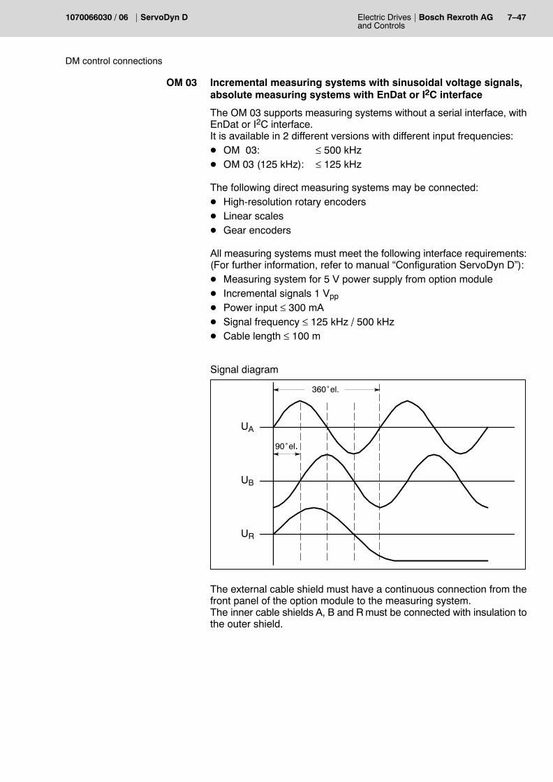
The present manual provides information on the installation of theServoDyn D drive modules.
Description ReleaseDate
Notes
DOK-SERV*D-IF*MANUAL**-MA06-EN-P 08.2004
E Bosch Rexroth AG, 1995 � 2004
Copying this document, giving it to others and the use orcommunication of the contents thereof without express authority, areforbidden. Offenders are liable for the payment of damages. All rightsare reserved in the event of the grant of a patent or the registrationof a utility model or design (DIN 34-1).
The data specified above only serve to describe the product. Nostatements concerning a certain condition or suitability for a certainapplication can be derived from our information. The giveninformation does not release the user from the obligation of ownjudgement and verification. It must be remembered that our productsare subject to a natural process of wear and aging.
Please read this manual before commissioning the ServoDyn D invert-ers. Store this manual in a place to which all users have access at anytime.
1.1 Intended use
This manual contains information required for the intended use of thisproduct.
The drive inverters describedD have been developed, manufactured, tested and documented in
compliance with the safety standards. These products pose nodanger to persons or property if they are used in accordance with thehandling stipulations and safety notes prescribed for their configur-ation, mounting, and proper operation.
D comply with the requirements ofD the EMC Directives (89/336/EEC, 93/68/EEC and 93/44/EEC)D the EMC product standard EN 61800-3 + A11D the Low-Voltage Directive (73/23/EEC)D the harmonized standards EN 50178 (VDE 0160) and EN
60146-1-1 (VDE 0558-11)D are designed for operation in industrial environments, i.e.
D no direct connection to public low-voltage power supply,D connection to the medium- or high-voltage system via a trans-
former.In residential environments, in trade and commerce as well as smallenterprises class A equipment may only be used if the following warn-ing is attached:
. This is a Class A device. In a residential area, this device may causeradio interference. In such case, the user may be required to intro-duce suitable countermeasures, and to bear the cost of the same.
Before putting the drive inverters into operation, ensure that the machinewhich the inverters are to be installed in meets the stipulations of the ma-chinery directive (98/37/EEC, 98/79/EEC) and the EMC directive(89/336/EEC).
The faultless, safe functioning of the product requires proper transport,storage, erection and installation as well as careful operation.
1�2 Electric Drivesand Controls
Bosch Rexroth AG ServoDyn D 1070066030 / 06
Safety instructions
1.2 Qualified personnel
The requirements as to qualified personnel depend on the qualificationprofiles described by ZVEI (central association of the electrical industry)and VDMA (association of German machine and plant builders) in:Weiterbildung in der Automatisierungstechnikedited by: ZVEI and VDMAMaschinenbauVerlagPostfach 71 08 64D-60498 Frankfurt.
The present manual is designed for drive technicians.
Programming, start and operation as well as the modification of programparameters is reserved to properly trained personnel! This personnelmust be able to judge potential hazards arising from programming, pro-gram changes and in general from the mechanical, electrical, or elec-tronic equipment.
Interventions in the hardware and software of our products, unless de-scribed otherwise in this manual, are reserved to our specialized person-nel.
Tampering with the hardware or software, ignoring warning signs at-tached to the components, or non-compliance with the warning notesgiven in this manual may result in serious bodily injury or material dam-age.
Only electrotechnicians as recognized under IEV 826-09-01 (modified)who are familiar with the contents of this manual may install and servicethe products described.
Such personnel areD those who, being well trained and experienced in their field and famil-
iar with the relevant norms, are able to analyze the jobs being carriedout and recognize any hazards which may have arisen.
D those who have acquired the same amount of expert knowledgethrough years of experience that would normally be acquired throughformal technical training.
With regard to the foregoing, please note our comprehensive range oftraining courses. Please visit our website at http://www.boschrex-roth.com for the latest information concerning training courses, teach-ware and training systems. Personal information is available from ourDidactic Center Erbach,Telephone: (+49) (0) 60 62 78-600.
Electric Drivesand Controls
1�3Bosch Rexroth AGServoDyn D1070066030 / 06
Safety instructions
1.3 Safety markings on products
Warning of dangerous electrical voltage!
Electrostatically sensitive components!
Warning of hazardous light emissions (optical fibre cable emitters)!
Lug for connecting PE conductor only!
Connection of shield conductor only
1�4 Electric Drivesand Controls
Bosch Rexroth AG ServoDyn D 1070066030 / 06
Safety instructions
1.4 Safety instructions in this manual
DANGEROUS ELECTRICAL VOLTAGEThis symbol is used to warn of a dangerous electrical voltage. Thefailure to observe the instructions in this manual in whole or in part mayresult in personal injury.
DANGERThis symbol is used wherever insufficient or lacking compliance withinstructions may result in personal injury.
CAUTIONThis symbol is used wherever insufficient or lacking compliance withinstructions may result in damage to equipment or data files.
. This symbol is used to draw the user�s attention to special circum-stances.
L This symbol is used if user activities are required.
Electric Drivesand Controls
1�5Bosch Rexroth AGServoDyn D1070066030 / 06
Safety instructions
1.5 Safety instructions concerning the described product
DANGERDanger of life through inadequate EMERGENCY-STOP devices!EMERGENCY-STOP devices must be active and within reach inall system modes. Releasing an EMERGENCY-STOP device mustnot result in an uncontrolled restart of the system! First check the EMERGENCY-STOP circuit, then switch the sys-tem on!
DANGERDanger for persons and equipment!Test every new program before starting up a system!
DANGERRetrofits or modifications may adversely affect the safety of theproducts described!The consequences may include severe injury, damage to equip-ment, or environmental hazards. Possible retrofits or modifica-tions to the system using third-party equipment therefore have tobe approved by Rexroth.
DANGERHealth hazards through destroyed electrical components!Do not destroy any built-in components. Dispose of destroyedcomponents in a proper manner.
DANGERDo not look directly into the LEDs in the optical fiber connection.Due to their high output, this may result in eye injuries.When the inverter is switched on, do not look into the LED or theopen end of a short connected lead.
DANGERPlease note your local, system-specific regulations and require-ments as well as the proper use of tools, hoisting and transportequipment as well as the applicable standards, regulations, andaccident prevention regulations.
1�6 Electric Drivesand Controls
Bosch Rexroth AG ServoDyn D 1070066030 / 06
Safety instructions
DANGEROUS ELECTRICAL VOLTAGEUnless described otherwise, maintenance works must be per-formed on inactive systems! The system must be protectedagainst unauthorized or accidental reclosing.Measuring or test activities on the live system are reserved toqualified electrical personnel!
DANGEROUS ELECTRICAL VOLTAGELethal voltages of up to 375 V DC against ground on all powerconnections and DC link connections!
The drives must not be switched on unless all covers have beenfitted! When the drive has been disconnected from mains, wait forup to 5 minutes until the system is de-energized before removingany covers.The drive must always be examined for safe isolation from sup-ply!
CAUTIONUse only spare parts approved by Rexroth!
CAUTIONDanger to the module!All ESD protection measures must be observed when using themodule! Prevent electrostatic discharges!
The following protective measures must be observed for modules andcomponents sensitive to electrostatic discharge (ESD)!D Personnel responsible for storage, transport, and handling must have
training in ESD protection.D ESD-sensitive components must be stored and transported in the
prescribed protective packaging.D ESD-sensitive components may only be handled at special ESD-
workplaces.D Personnel, working surfaces, as well as all equipment and tools
which may come into contact with ESD-sensitive components musthave the same potential (e.g. by grounding).
D Wear an approved grounding bracelet. The grounding bracelet mustbe connected with the working surface through a cable with an inte-grated 1 MW resistor.
D ESD-sensitive components may by no means come into contact withchargeable objects, including most plastic materials.
D When ESD-sensitive components are installed in or removed fromequipment, the equipment must be de-energized.
Electric Drivesand Controls
1�7Bosch Rexroth AGServoDyn D1070066030 / 06
Safety instructions
1.6 Documentation, software release and trademarks
Documentation
The present manual provides information on the installation of theServoDyn D drive modules.
D The current software release number can be viewed by selectingparameter S-0-0030 with the DSS-D Commissioning and ServiceSystem, or in the �Software� field of the module configuration display(DIAGNOSTICS " MODULE CONFIGURATION).
D For information concerning the current DSS software release, refer toHELP " ABOUT...
1�8 Electric Drivesand Controls
Bosch Rexroth AG ServoDyn D 1070066030 / 06
Safety instructions
D The current VM..B,C,D,F software release can only be read from the7-segment display during test operation. For this purpose, turn dipswitch �T� on the VM�s personality module �on�:
The following appears in a running, flashing display:�Cxx.ZZ.ddmmyyyy�
Where: xx = software release numberZZ = (internal)dd = software creation daymm = software creation monthyyyy = software creation year
Trademarks
All trademarks of software installed on Rexroth products upon deliveryare the property of the respective manufacturer.
Upon delivery, all installed software is copyright-protected. The softwaremay only be reproduced with the approval of Rexroth or in accordancewith the license agreement of the respective manufacturer.
MS-DOSr and Windowst are registered trademarks of MicrosoftCorporation.
PROFIBUSr is a registered trademark of the PROFIBUS Nutzerorgani-sation e.V. (user organization).
SERCOS interfacet is a registered trademark of Interessengemeins-chaft SERCOS interface e.V. (Joint VDW/ZVEI Working Committee).
Electric Drivesand Controls
2�1Bosch Rexroth AGServoDyn D1070066030 / 06
Switch cabinet structure
2 Switch cabinet structure
2.1 Drive components
Mains connection module Type NAA
Contains all required fuses and power-up components for supply mod-ules VM..B,C,D,F with current regeneration, NAA optionally with inte-grated mains filter.The mains voltage of 3 x 400...460 V a.c. is directly connected here.Communication with the supply module takes place via control lineswhich can be plugged into the supply module.NAA modules with an additional filter with symmetrical effect are avail-able for connection to a public network.
Line wiring module Type NV
Contains fuses, mains contactor and an optional mains filter for supplymodules VMA..K.The mains voltage of 3 x 400...460 VAC is directly connected to this mo-dule.
Mains filter
Required interference suppression measure as specified in the EMCDirective (89/336 EEC). Thus, limit class A (B on request) for radio inter-ference in accordance with EN 55 011 (VDE 0875) is complied with.
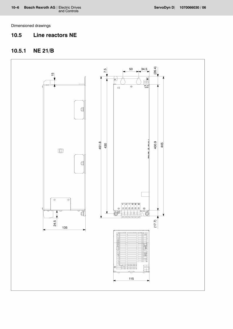
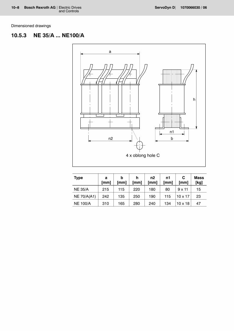
Line reactor Type NE
The line reactor type NE should be installed between the mains connec-tion module and supply modules VM...B,C,D,F with current regener-ation. It decouples the d.c. link from the mains. Supply modules VMA..K with ballast switches do not require a line reac-tor.
Backplane modules Type RM
The backplane modules facilitate the mounting and wiring ofVMA..B,C,D and DMA..A,B,D inverter modules.
They contain the following connections:D the terminal block for the power connectionsD connection terminals for the brake connectionD conductor bars for the link connectionD earthing link for the PE conductor connection
2�2 Electric Drivesand Controls
Bosch Rexroth AG ServoDyn D 1070066030 / 06
Switch cabinet structure
The backplane modules also bear the fan units for heat sink ventilationof the inverter modules. The supply modules and three-phase modules are slotted into thebackplane modules, plugged into the terminal blocks and locked.
Supply module Type VMA..K
The VMA..K supply module is directly connected to 3 x 400...460 VACusing the line wiring module. It generates a d.c. link voltage of 670 Vfrom the mains voltage.The link connection to the DM..K three-phase modules is establishedvia covered conductor bars.
Supply module Type VMA..KR
The VMA..KR supply module is connected to the 3 x 400...460 VAC viathe mains connection module and the line reactor. It generates a d.c.link voltage of 670 V from the mains voltage.The link connection to the DM..K three-phase modules is establishedvia covered conductor bars.
Supply modules Type VMA...B,C,D
The supply modules VMA..B,C,D are connected to the 3 x 400...460 VAC via the mains connection module and the line reactor. They gener-ate a d.c. link voltage of 670 V from the mains voltage.The link connection to the three-phase modules DMA..A,B,D is estab-lished via conductor bars integrated in the backplane modules. Whencombined with DM..K in compact mechanics, the d.c. link connection isachieved with the d.c. link connection accessory.
Supply module Type VMW..F
The VMW 180F supply module is designed for a maximum output of120 kW and equipped with an integrated water cooling. It is directly con-nected to the 3 x 400...460 VAC mains network via the mains connec-tion module and the line reactor. The DC link connection to the three-phase current modules is made bycovered current bars. If combined with modules without water cooling,the DC link connection must be made using the DC link accessory in-cluding a fuse.
Electric Drivesand Controls
2�3Bosch Rexroth AGServoDyn D1070066030 / 06
Switch cabinet structure
Three-phase modules Type DM..K and Type DM..A,B,D,F
The servo motors type SF and SR or asynchronous motors type DU aswell as asynchronous standard motors or special motors, such as high-frequency spindles, built-in motors or linear motors are operated usingthe DM three-phase modules.Inverter modules with SERCOS interface contain the entire softwareon the plug-in Personality Module. Furthermore, a Memory Card can beused as a standard. Inverter modules with other interfaces have an integrated softwarepackage.
24 V load power supply unit
The VMA supply module must be supplied from an external 24 V d.c.load power supply unit in accordance with EN 61131 (mean value 20.4 �28.8 V).
CAUTIONOvervoltage!The 24 VDC must satisfy the �safety separation� requirements. Therequirements in accordance with the overvoltage category IIIshould be noted on the primary side !
In the inverters, the extra-low-voltage circuits are safety-separated fromthe mains circuit (safety separation to EN 50178).
2�4 Electric Drivesand Controls
Bosch Rexroth AG ServoDyn D 1070066030 / 06
Switch cabinet structure
2.2 Installation compartment
The ServoDyn D inverter modules are installed in a switch cabinet.Their component depth is fairly low, i.e. 270 mm or 290 mm, dependingon the mechanics.The switch cabinets must at least conform to the IP 54 protection stan-dard (dust filter in front of the air inlet and air outlet).
The inverters are mounted in a vertical position with the terminals to thebottom.The cooling air flow passes through the modules from the bottom to thetop and must not be obstructed by other switch cabinet components orparts. In addition, a minimum clearance of 100 mm should be providedboth above and below the inverter.No minimum lateral clearance need be provided.
The air temperature inside the cabinets may be between 0...+55 _C (de-rating above 45 _C).+55 _C is the maximum permitted supply air temperature for the upper-most inverter if several inverters are stacked one above the other.Constructive measures have to be taken to ensure the appropriate airflow direction in the switching cabinet in this case.
CAUTIONDanger for product!The ambient air must be free from high concentrations of dust,acids, alkalis, corrosives, salts, metal vapors etc. Condensation on the modules is not permitted!
Condition in direct environment
For safety separation, the requirements of pollution degree 2 must notbe exceeded.For a definition of the pollution degree, refer to HD 625.1 and EN 50178.
Electric Drivesand Controls
2�5Bosch Rexroth AGServoDyn D1070066030 / 06
Switch cabinet structure
2.3 Layout of the drive components
The following points must be considered in the layout of the drive com-ponents:D All inverter modules in a d.c. link should be structured in one row if
possible. A multiple-row structure is however also possible if the ap-propriate accessories are used (cf. page 3�14).
D A maximum of 9 three-phase modules can be added to one VMAsupply module. This depends on:D the rated power of the VM supply moduleD the 24 V power input of all modules and all backplane modules.
The maximum load on any supply module is 14 A (for power inputdata, refer to page 5�17)
D Space requirements:Depth = 288 mm, 222 mm in the case of cold module mountingWidth = 50 mm grid, 72 mm in the case of cold module mountingHeight = 521.5 mm, 704 mm provides clearance for ventilation
(DMA..A,B,D)588 mm (DMW ..F)452.5 mm, 600 mm provides clearance for ventilation
(DM..K)D The mains connection module or the optional line wiring module is
mounted on the left-hand side.D The supply module is positioned to the right of it, all further inverter
modules are arranged to the right of the VMA supply module.D Line reactors for upright installation must be fastened vertically in
order to ensure cooling by natural convection.D The power cables and control lines should be separately laid to en-
sure EMC (distance >100 mm). The following scheme can beadopted in the case of larger cabinets:
Power cables
Control lines
Switch cabinet
Power cables
D The mains supply cable is connected to the top side of the NAA or theNV module.
D The motors� power cables are connected to the bottom side of themodule. They should enter the switch cabinet from the bottom.
D Control lines to the modules� front connectors are led upward into acable duct on the top side of the inverter module.
2�6 Electric Drivesand Controls
Bosch Rexroth AG ServoDyn D 1070066030 / 06
Switch cabinet structure
D All drive components and electronic components such as CNC orPLC components should be arranged separately (distance > 100 mm).
NA VM..�D DM..�D
NC
Mains supplycable 3 x 400 V
Spacefor themainsfilter
Line reac-tor(basemounting)
Power cablesmotors
Signal cablesmotor encoderanddirect measuringsystem
PLC
EMC barrierInterface
. The line reactorgets very hot.For installation,please make surethat the drivemodules do notget too hot.
Basic switch cabinet structure, example of a possible layout
Electric Drivesand Controls
2�7Bosch Rexroth AGServoDyn D1070066030 / 06
Switch cabinet structure
2.3.1 Installation in compliance with UL/CSA
A UL/CSA certification for the U.S. and Canada is available for a largenumber of ServoDyn D inverter types. These modules are listed in the�Product Identity 23 MB�, File No. E214694.
. For available components with UL/CSA approval, refer to �Servo-Dyn D, Configuration manual�, part number on page 1�7.
Installation in compliance with UL/CSA
In order to obtain a UL/CSA-compliant installation, the following mustbe noted in addition to the use of the certified components:D Systems may only be used in environments with pollution severity 2.D Observe the tightening torques on the connection terminals.D The insulated copper wires must be specified for 60/75_C as a mini-
mum.D Only use insulated cable of class 1 or equivalent,
e.g. according to UL Style 1015 (on motor side, H07: U0/U:600/1000 V) and UL Style 1007 or 1569 (on mains side, H05: U0/U:300/500 V)
D Suitable for installation in symmetrical supply networks with a short-circuit current of � 10 kA with max. 460 V +10 %.
Operation in compliance with UL/CSA
For UL/CSA-compliant operation, the bimetal function (I2t monitoring)must be activated in the inverters using parameter P-0-0053 in order toprovide motor protection:D IN of the motor is automatically retrieved from the electronic rating
plate to the I2t- monitoring function.D P-0-0053 is only used to set the desired time constant:
(corresponds to release characteristics of bimetal relay)
2�8 Electric Drivesand Controls
Bosch Rexroth AG ServoDyn D 1070066030 / 06
Switch cabinet structure
Notes:
Electric Drivesand Controls
3�1Bosch Rexroth AGServoDyn D1070066030 / 06
Installation
3 Installation
3.1 Standard installationAll inverter modules are installed in a vertical position with the terminalsto the bottom. They should be connected on a level metal surface usingtwo or four screws or bolts depending on size. The recommended size isM5. A conductive connection to the mounting surface must be estab-lished via the screws or bolts.
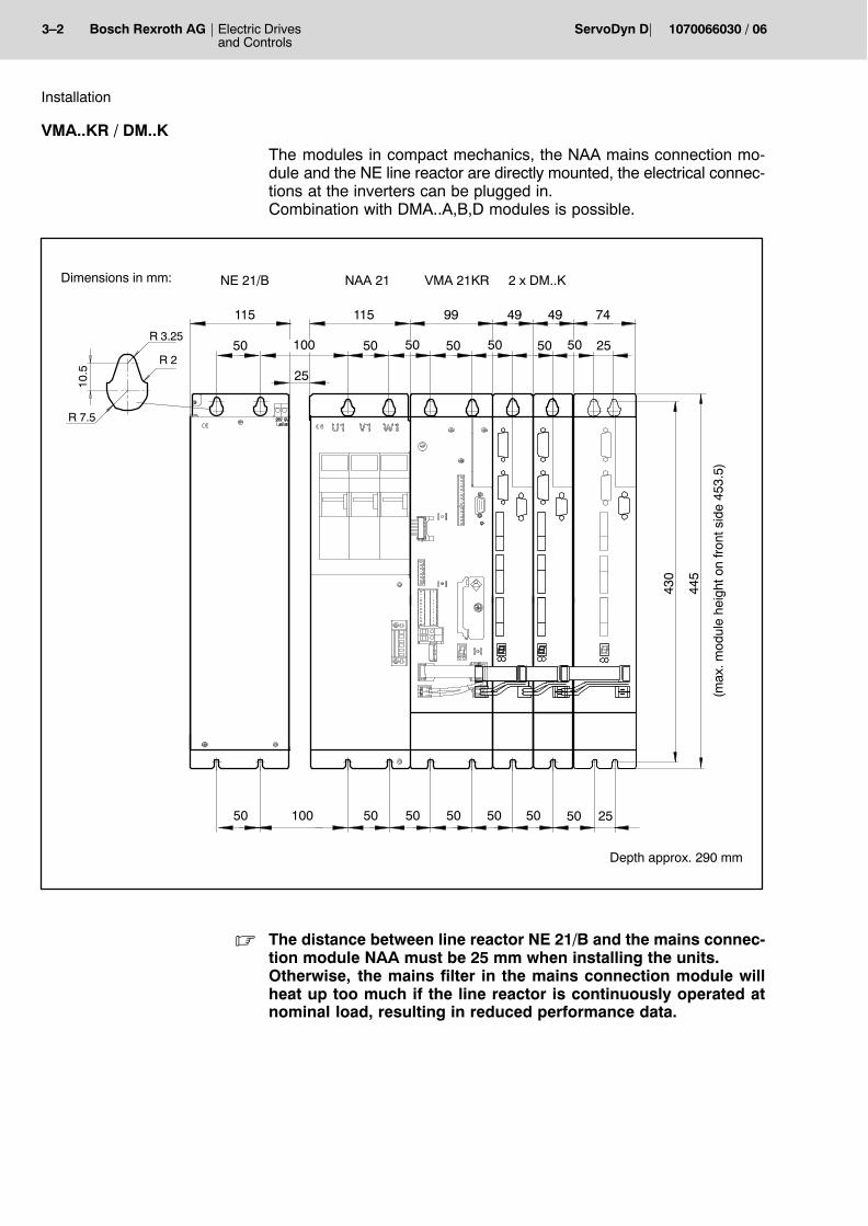
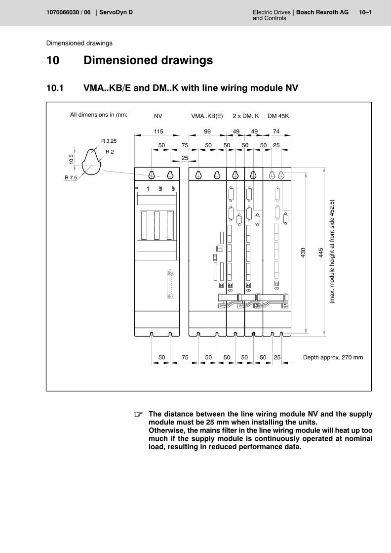
VMA..K / DM..KThe modules in compact mechanics and the NV line wiring module aredirectly mounted, all electrical connections can be plugged in.Combination with DMA..A,B,D modules is possible.
25
25
74
50
99 49
50
49
5050
50 50 50
430
445
Dimensions in mm:
115
50
50 75
10.5
R 3.25
R 2
R 7.5
NV VMA..KB(E) 2 x DM..K
(max
. mod
ule
heig
ht o
n fr
ont s
ide
452.
5)
75
25
50
486
DMA..A
534
48
56
50
DM 45K
. The distance between the line wiring module NV and the supplymodule must be 25 mm when installing the units.Otherwise, the mains filter in the line wiring module will heat up toomuch if the supply module is continuously operated at nominalload, resulting in reduced performance data.
3�2 Electric Drivesand Controls
Bosch Rexroth AG ServoDyn D 1070066030 / 06
Installation
VMA..KR / DM..K
The modules in compact mechanics, the NAA mains connection mo-dule and the NE line reactor are directly mounted, the electrical connec-tions at the inverters can be plugged in.Combination with DMA..A,B,D modules is possible.
10050
115 99 49
50
49
50
50 50 50
430
445
Depth approx. 290 mm
Dimensions in mm:
115
50
50 50
10.5
R 3.25
R 2
R 7.5
NAA 21 VMA 21KR 2 x DM..K
(max
. mod
ule
heig
ht o
n fr
ont s
ide
453.
5)
50 100
NE 21/B
50 50
25
2550
25
74
50
. The distance between line reactor NE 21/B and the mains connec-tion module NAA must be 25 mm when installing the units.Otherwise, the mains filter in the mains connection module willheat up too much if the line reactor is continuously operated atnominal load, resulting in reduced performance data.
Electric Drivesand Controls
3�3Bosch Rexroth AGServoDyn D1070066030 / 06
Installation
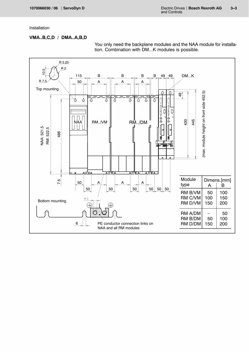
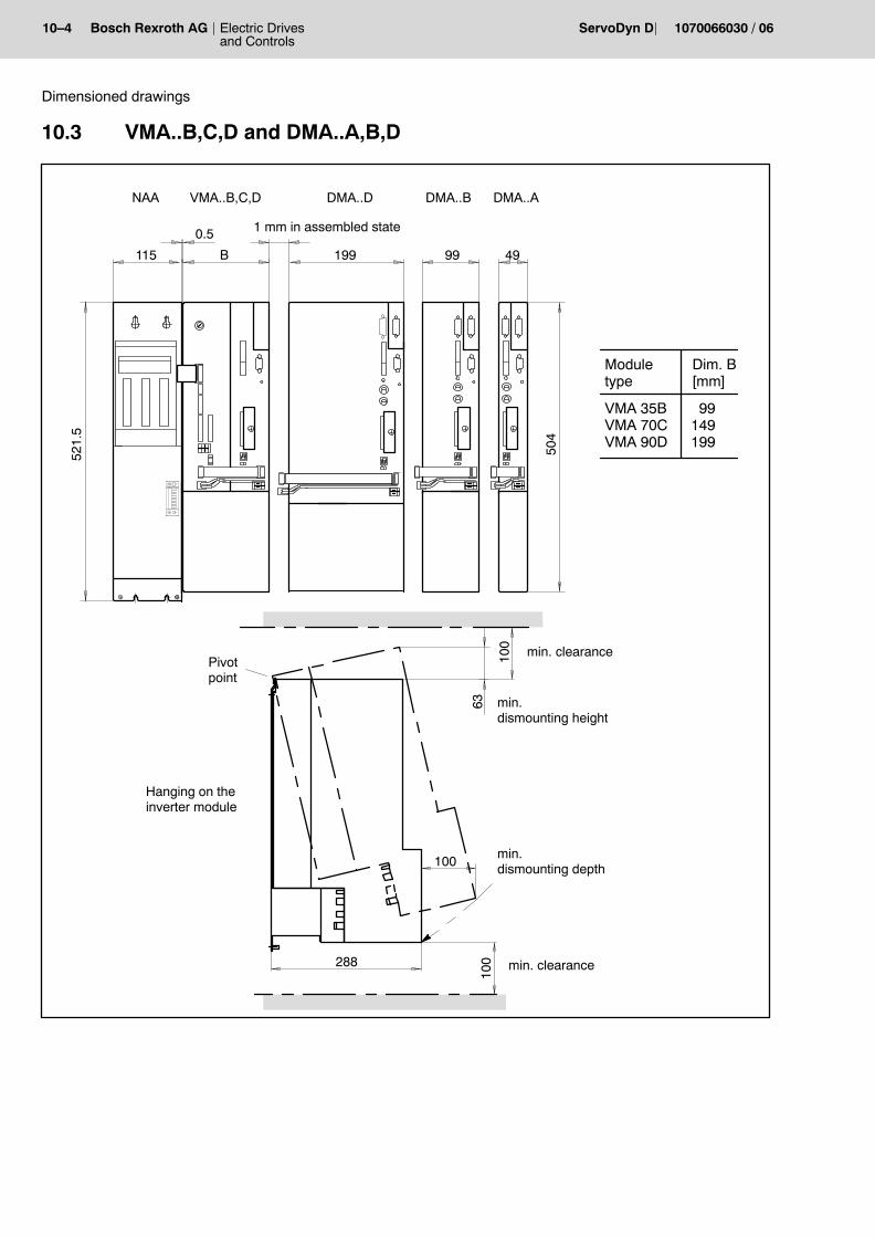
VMA..B,C,D / DMA..A,B,D
You only need the backplane modules and the NAA module for installa-tion. Combination with DM...K modules is possible.
RM B/VMRM C/VMRM D/VM
RM A/DMRM B/DMRM D/DM
RM../VM
Top mounting
Bottom mounting
PE conductor connection links onNAA and all RM modules
6
486
7.5
115 B B B B
50 A A A
50 A A A
50 50 50 50
NAA
10.5
R�3.25
R�2
R�7.5
RM../DM
48
49 49
505043
0
445
Moduletype
Dimens.[mm]
50100150
�50
150
100150200
50100200
A B
DM...K
RM
: 522
.5
NA
A: 5
21.5
(max
. mod
ule
heig
ht o
n fr
ont s
ide
452.
5)
3�4 Electric Drivesand Controls
Bosch Rexroth AG ServoDyn D 1070066030 / 06
Installation
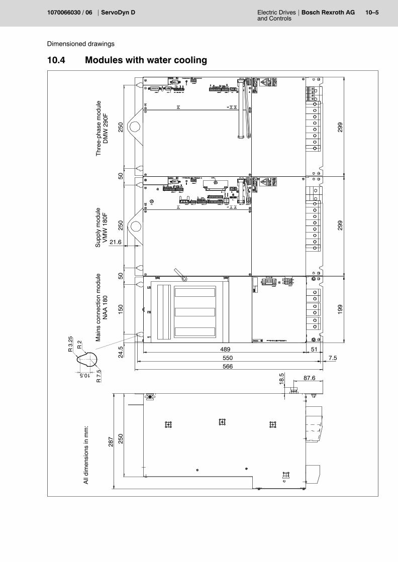
3.2 Mounting of VMW..F / DMW..F with water cooling
VMW and DMW are equipped with water cooling. They are installed to-gether with a standard NAA module.
21.6
250
50
51
250
5015
024
.5
7.5
489
550
566
299
299
199
Mai
ns c
onne
ctio
n m
odul
eN
AA
180
Sup
ply
mod
ule
VM
W 1
80F
Thr
ee-p
hase
mod
ule
DM
W 2
90F
10.5
R 3
.25
R 2
R 7
.5
Electric Drivesand Controls
3�5Bosch Rexroth AGServoDyn D1070066030 / 06
Installation
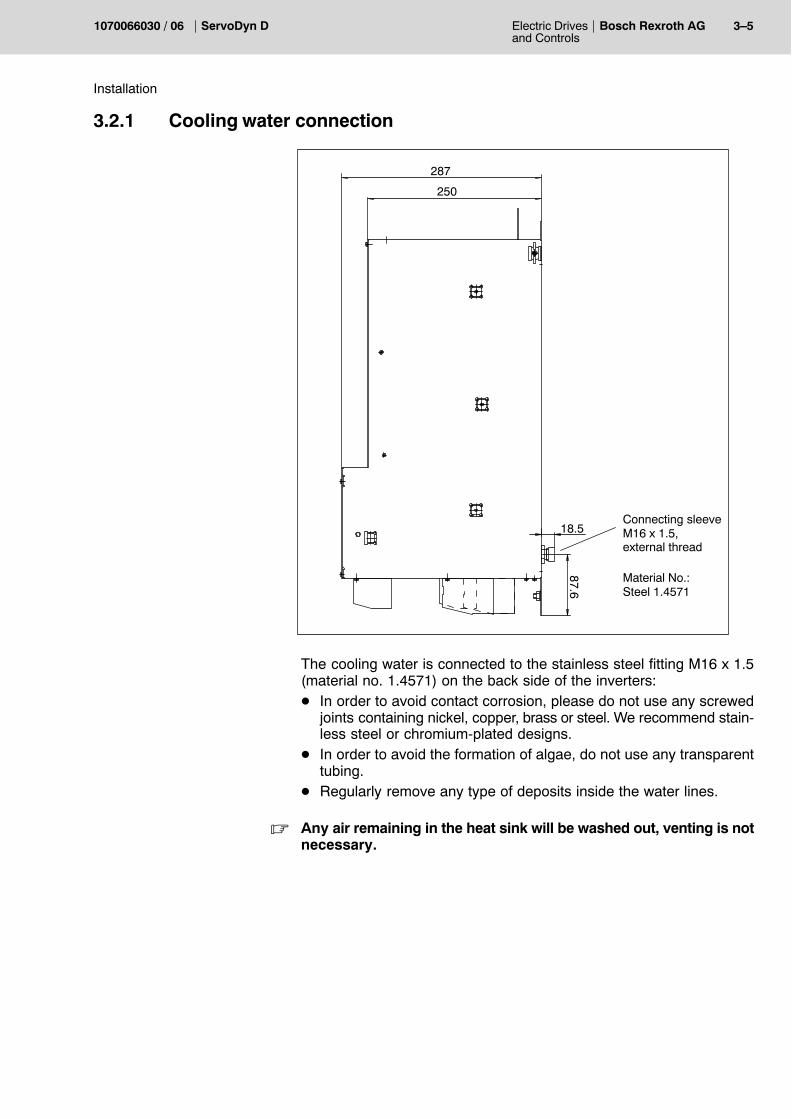
3.2.1 Cooling water connection
250
287
87.6
18.5Connecting sleeveM16 x 1.5,external thread
Material No.:Steel 1.4571
The cooling water is connected to the stainless steel fitting M16 x 1.5(material no. 1.4571) on the back side of the inverters:D In order to avoid contact corrosion, please do not use any screwed
joints containing nickel, copper, brass or steel. We recommend stain-less steel or chromium-plated designs.
D In order to avoid the formation of algae, do not use any transparenttubing.
D Regularly remove any type of deposits inside the water lines.
. Any air remaining in the heat sink will be washed out, venting is notnecessary.
3�6 Electric Drivesand Controls
Bosch Rexroth AG ServoDyn D 1070066030 / 06
Installation
Operating conditions
D Water inlet temperature: 10...40_CD Water quantity needed: min. 5 l/minD Water pressure: max. 5 barD Pressure loss per inverter: max. 0.6 barD Temperature rise:
D DMW 290F: fs = 8 kHz 6 K/100 Afs = 4 kHz 4 K/100 A
D VMW 180F: 4.5 K/100 A
Water quality
In order to guarantee safe operation, the cooling water must satisfy thefollowing conditions regarding soluble chemicals and insoluble sub-stances:D Concentration of hydrogen ions: pH 7...9D Total hardness Dmax: 10_ (German)
(1_ German = 1.25 Engl. deg. = 1.05 US degrees = 1.8 French de-grees)
D Chlorides: max. 20 mg/lD Nitrates: max. 10 mg/lD Sulfates: max. 100 mg/lD Insoluble substances: max. 250 mg/lD Specific resistance: min. 2000 W/cm
Tap water will in most cases satisfy these requirements.If your tap water has inadmissible properties, a closed cooling water cir-cuit must be used in which the cooling water can be permanentlychecked.
. In closed cooling water circuits, an algaecide must furthermore beadded to the water. Check the cooling water regularly.
Please note that the specific resistance of the cooling water maychange if an anticorrosive agent or an antifreeze is used in a recirculat-ing cooling system.
. The water inlet temperature should not be below 20 _C. Condensa-tion on the water-conducting components, particularly the powersemiconductors, should be avoided.
Failures that are due to the bad cooling water quality, or damagescaused by condensation, are not covered by the guaranty.
Electric Drivesand Controls
3�7Bosch Rexroth AGServoDyn D1070066030 / 06
Installation
3.3 Cold module installation
For cold module installation, the inverter modules are fastened so thatthe heat sinks protrude through the mounting plate and thus from theswitch cabinet.Cold module installation guarantees almost complete heat dissipationoutside of the switch cabinet. This means that the temperature insidethe switch cabinet remains within permissible limits even without addi-tional ventilation or cooling measures.
Design IP 20
The special design without sealing against the inside of the switch cabi-net (protection standard IP 20) must be cooled with an enclosed ventila-tion system in order to guarantee the switch cabinet�s protectionstandard IP 54.
Backplane cut-out
Hei
ght 4
06.2
5
Width = VM + n x DMA + 3
3�8 Electric Drivesand Controls
Bosch Rexroth AG ServoDyn D 1070066030 / 06
Installation
3.4 Link connection
The d.c. link voltage generated by the supply module is transmitted tothe three-phase module via conductor bars.
3.4.1 VMA..K und DM..K
L The d.c. link connection is achieved with conductor bars �C� and �D� atthe front side of the modules:
1. Release fastening screw below the cover, unhinge and removecover upward.
2. Release screws of pre-assembled conductor bars, push bars belowthe fastening screws of the adjoining left module and tighten screwsagain.
C
D
CAUTIONTighten the d.c. link joints with 3 Nm to protect the power unit.
1. Remove right-hand end cover from cover ofVMA..K by slightly bending the metal sheet.
2. Insert this end cover as shock-protectioncover with covered cable bushings into thecover of the last DM..K to the right-handside.
3. Reinstall all covers.
DANGEROUS ELECTRICAL VOLTAGEConductor bars carry a hazardous voltage during operation.The shock-protection covers must always be installed at bothends of any module row.
Electric Drivesand Controls
3�9Bosch Rexroth AGServoDyn D1070066030 / 06
Installation
3.4.2 VMA..B,C,D and DMA..A,B,D with backplane modules
The conductor bars are captivated in the backplane module terminalblocks.
L Mounting using a SW 4 Allan key:
1. Unscrew the clamps (1).2. Unscrew the clamps (2), move the conductor bars into the adjoining
terminal block and tighten the screws.3. Fasten the second end of the conductor bar using the terminal
clamp (1).4. Cover the right backplane module terminal block of every module
row with the terminal block end cover from the VMA supply moduleaccessory set. There is a second cover in the link terminal accessoryset which can be used if there are two module rows.
DANGEROUS ELECTRICAL VOLTAGEConductor bars carry a hazardous voltage during operation.It is absolutely necessary to attach the terminal block end coverto the right end of each module row.
D
C
2 1 2 1
1 2 1 2D
C
CAUTIONTighten the d.c. link joints with 5 Nm to protect the power unit.
3�10 Electric Drivesand Controls
Bosch Rexroth AG ServoDyn D 1070066030 / 06
Installation
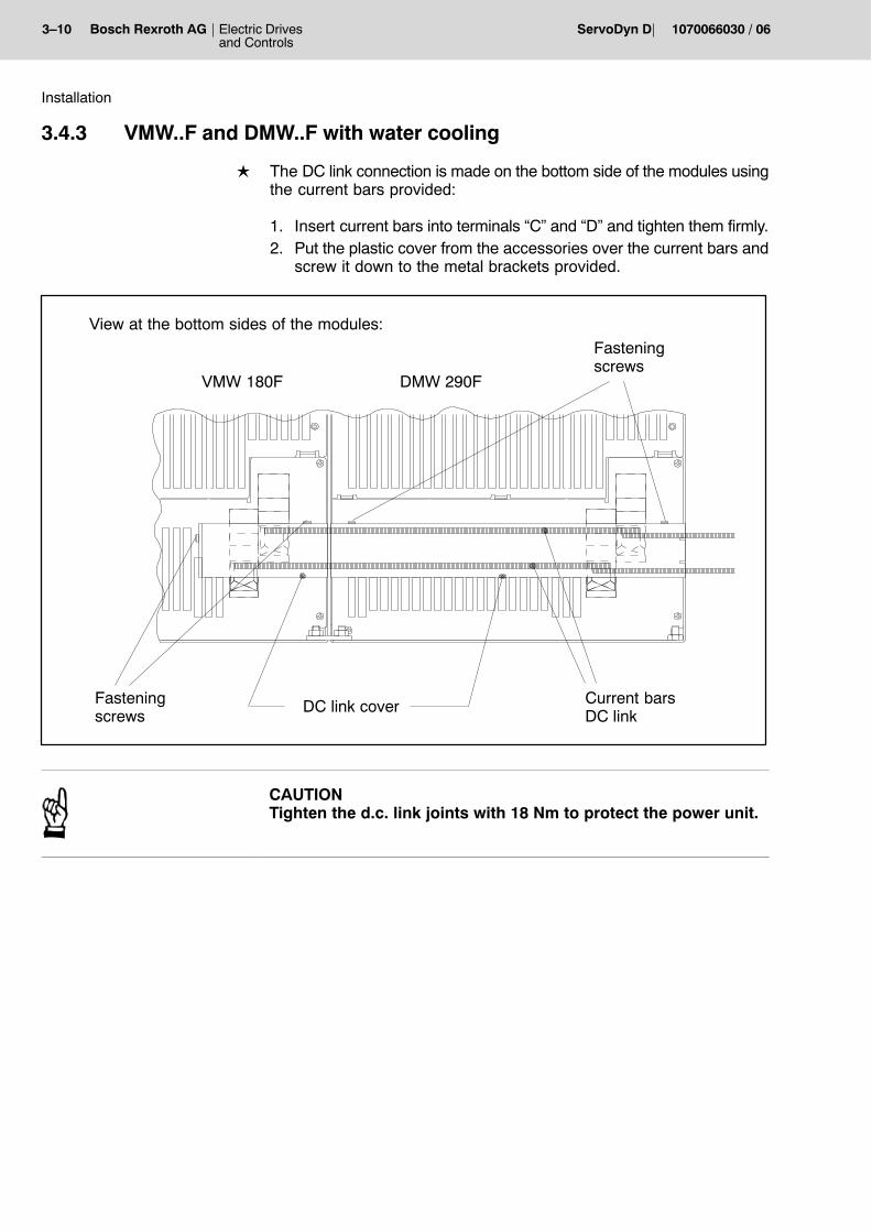
3.4.3 VMW..F and DMW..F with water cooling
L The DC link connection is made on the bottom side of the modules usingthe current bars provided:
1. Insert current bars into terminals �C� and �D� and tighten them firmly.2. Put the plastic cover from the accessories over the current bars and
screw it down to the metal brackets provided.
Current barsDC link
DC link coverFasteningscrews
Fasteningscrews
VMW 180F DMW 290F
View at the bottom sides of the modules:
CAUTIONTighten the d.c. link joints with 18 Nm to protect the power unit.
D C
Electric Drivesand Controls
3�11Bosch Rexroth AGServoDyn D1070066030 / 06
Installation
3.4.4 DC link connection
The DC link connection (DC link) is an externally accessible DC link ter-minal, via which the DC link can be flexibly extended. Possible options:D CD link on the right, left (for backplane modules)D DC link for compact mechanics, on the right, leftD DC link connection with integrated fuse (for water-cooled modules).
Module combination
DC link option for combining modules with compact mechanics andmodules with a backplane module.The DC link connection is available for compact mechanics and forbackplane modules, for both left-sided and right-sided installation.
NAA
DMA..A DM..K
VM 35
right-side d.c. link
DM..ADM..KVM 21K
left-side d.c. link
compact mech-anics, right-sided.c. link
compact mech-anics, left-sided.c. link
Additional DM..K moduleL The d.c. link connection is made using the right-side d.c. link:
1. Remove end cover of the terminal block ofthe backplane modules and cover of the d.c.link.
2. Insert d.c. link from the right side into the ter-minal block of the backplane module andmake connection using the d.c. link bars.
3. Reinstall d.c. link cover.
C D
3�12 Electric Drivesand Controls
Bosch Rexroth AG ServoDyn D 1070066030 / 06
Installation
4. Remove cover from DM..K and cover fromthe right-side d.c. link for compact mecha-nics.
5. Insert d.c. link from the right side into the ter-minal block of the compact mechanics andmake connection using the d.c. link bars.The minimum cross-section of the flexiblecable depends on the modules connecteddownstream.
6. Reinstall DC link cover and screw it downwith screw M3 x 6.
Additional DMA..A,B,D moduleL The d.c. link connection is made using the left-side d.c. link:
1. Remove cover of the d.c. link.
2. Insert d.c. link from the left side into the termi-nal block of the backplane module and makeconnection using the d.c. link bars. The otherside of the terminal block must be protectedwith an end cover.
3. Reinstall the cover.
4. Remove cover from VM..K and cover andcover from the left-side d.c. link for compactmechanics.
5. Insert d.c. link from the left side into the termi-nal block of the VM..K and make connectionusing the d.c. link bars.The minimum cross-section of the flexiblecable depends on the modules connecteddownstream.
6. Reinstall DC link cover and screw it downwith screw M3 x 6.
DANGEROUS ELECTRICAL VOLTAGEConductor bars carry a hazardous voltage during operation.It is important to reinstall the complete shock-protection covers.
Electric Drivesand Controls
3�13Bosch Rexroth AGServoDyn D1070066030 / 06
Installation
DC link with integrated fuse option for combining water-cooled mod-ules and other modules.
NAA 180 VMW ..F
DC linkwith integrated fuse
leads to any otherDC link connection(cf. above)
. The fuse of the DC link connection with integrated fuse must matchthe service conditions of the module combination. A 100 A fuse isdelivered together with the unit.
L Make DC link connection using the DC link with integrated fuse:
1. Insert fuse holder into lateral slots on the inverter and screw themdown there.
2. Insert the current bars into the terminals and tighten them there (3.7Nm).
3. Remove protective film from the cover, place cover on the fuseholders and screw it down.
3.
1.
2.3.
3�14 Electric Drivesand Controls
Bosch Rexroth AG ServoDyn D 1070066030 / 06
Installation
Two-row module arrangement
D Using the DC link connection option, DMA..A,B,D with backplanemodule can be operated in two rows on top of each other at one DClink. In order to ensure the shortest possible line routing, the far right endof each module row is equipped with a right-hand DC link.
D Using the DC link connection compact mechanics DM..K mod-ules can be operated in two rows on top of each other at one DC link. In order to ensure the shortest possible line routing, the far right endof each module row is equipped with a right-hand DC link compactmechanics.
. The flexible DC link leads must be twisted and shielded in order toavoid interference.
For extending the signal cross-connection X810 and the 24V cross-connection X820, prefabricated cables are available. The shield connection 1070 084 345 should be additionally used for the24V extension in compact mechanics.
Electric Drivesand Controls
3�15Bosch Rexroth AGServoDyn D1070066030 / 06
Installation
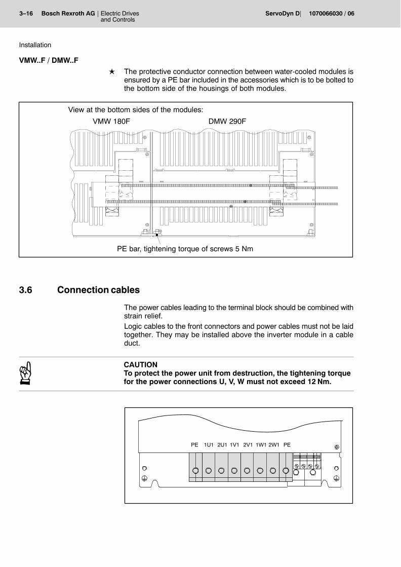
3.5 Protective earth connection between the modules
VMA..B,C,D / DMA..A,B,D
L The protective earth connection between the modules mentionedabove is established via the earthing links, which are mounted on thebottom right of each inverter module or backplane module:
1. Unscrew the earthing links� fastening nuts2. Mount the modules3. Swing the link over to the adjoining module and screw it down on
both sides.
Protective earth links onNAA and all RM modules Tightening torque 5 Nm.
6
M 6
VMA..K / DM..K
L The protective earth connection between modules in compact mech-anics is made using an earth bar at each DM...K and a link at the NV:
1. Release screws of pre-assembled protective earth bar at the mo-dule front side, push bar below the fastening screw of the adjoiningmodule to the left.
2. Reinstall the protective earth conductor bar.3. Swing link at the mounting side of NV towards VMA...K and screw it
down at both sides.
Protective earth links be-tween NV and VMA...Kmodules.Tightening torque 5 Nm.
6M�6
NV VMA..K DM..K
Tightening torque3 Nm.
3�16 Electric Drivesand Controls
Bosch Rexroth AG ServoDyn D 1070066030 / 06
Installation
VMW..F / DMW..F
L The protective conductor connection between water-cooled modules isensured by a PE bar included in the accessories which is to be bolted tothe bottom side of the housings of both modules.
PE bar, tightening torque of screws 5 Nm
VMW 180F DMW 290F
View at the bottom sides of the modules:
3.6 Connection cables
The power cables leading to the terminal block should be combined withstrain relief.Logic cables to the front connectors and power cables must not be laidtogether. They may be installed above the inverter module in a cableduct.
CAUTIONTo protect the power unit from destruction, the tightening torquefor the power connections U, V, W must not exceed 12 Nm.
1U1 2U1 1V1 2V1PE 1W1 2W1 PE
Electric Drivesand Controls
4�1Bosch Rexroth AGServoDyn D1070066030 / 06
Connection overview
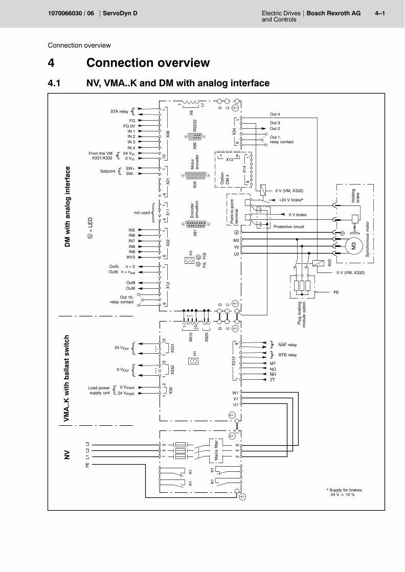
4 Connection overview
4.1 NV, VMA..K and DM with analog interface
SW�SW+
U1V1W1
X81
0
1 10
D C
L1L2
L3
U2
V2
W2
X31
21
8
D C
X8
1 17
NV
D C
K03
M3
...
MT
X06
101
FGI
FG
X99
RS23
2
61
X34
FG 0VFG
X05
Out 2
Out 1,relay contact
13
5
24
6
H1
IN 3IN 2
* Supply for brakes:24 V � 10 %
PE
Load powersupply unit
Out 4
Out 3
IN 1
STA relay
NAF relay
12
X30
H1
NONHZT
X82
0
24 VPWR
0 VPWR
121
...24 VOut
X33
1
121
...0 VOut
X33
2
BTB relay
X21
1
A_IN2�A_IN2+
A_IN3�A_IN3+
Setpoint
6
A_Out1�A_Out1+
X11
1
A_Out2�A_Out2+
4
IN6IN5
X22
1
IN8IN7
IN10IN9
6
Out6: n = nset
Out5: n = 0
X12
1
Out8
8
Out9
Out 10,relay contact
X81
not usedK1
K1
K1
K1
IN 4
+24 V brake*
0 V (VM, X332)
0 V brake
Protective circuit
0 V (VM, X332)
PE
0 VIn
24 VInFrom the VMX331/X332
VM
A..K
wit
h b
alla
st s
wit
ch
OM�4
Option
81
X14
81X13
DM
wit
h a
nal
og
in
terf
ace
= LE
D
Mot
oren
code
rE
ncod
ersi
mua
tion
Mai
ns f
ilter
Poi
nt-t
o-po
int
term
inal
Plu
g br
akin
gm
odul
e op
tion
Hol
ding
brak
e
Syn
chro
nous
mot
or
4�2 Electric Drivesand Controls
Bosch Rexroth AG ServoDyn D 1070066030 / 06
Connection overview
4.2 NV, VMA..K and DM with Motion Control
Reference camHome position
Block select 24
Start/Stop20
21
U1V1W1
X81
0
1 10
D C
L1L2
L3
U2
V2
W2
X31
21
8
D C
X8
1 17
NV
D C
K03
M3
...
MT
X06
101
FGI
FG
X99
RS23
2
61
X34
FG 0VFG
X05
Temperature warning
13
5
24
6
H1
2221
* Supply for brakes:24 V � 10 %
PE
Load powersupply unit
Out 4
Out 3
20
STA relay
NAF relay
12
X30
H1
NONHZT
X82
0
24 VPWR
0 VPWR
121
...24 VOut
X33
1
121
...0 VOut
X33
2
BTB relay
X21
16
X11
14
X22
16
Axis activeAxis has been referenced
X12
1
End of program/block
8
Home position reached
Relay contactMC status
X81
not used
Block select
K1
K1
K1
K1
23
+24 V brake*
0 V (VM, X332)
0 V brake
Protective circuit
0 V (VM, X332)
PE
Mode
In position
not used
not used
0 VIn
24 VInFrom the VMX331/X332
VM
A..K
wit
h b
alla
st s
wit
ch
OM�4
Option
81
X14
81X13
DM
wit
h M
oti
on
Co
ntr
ol
= LE
D
Mot
oren
code
rE
ncod
ersi
mua
tion
Poi
nt-t
o-po
int
term
inal
Hol
ding
brak
e
Syn
chro
nous
mot
or
Plu
g br
akin
gm
odul
e op
tion
Mai
ns f
ilter
Electric Drivesand Controls
4�3Bosch Rexroth AGServoDyn D1070066030 / 06
Connection overview
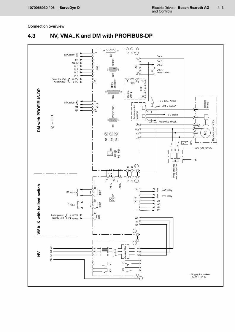
4.3 NV, VMA..K and DM with PROFIBUS-DP
U1V1W1
X81
0
1 10
D C
L1L2
L3
U2
V2
W2
X31
21
8
D C
X8
1 17
NV
D C
K03
M3
...
MT
X06
101
FG
IF
G
X99
RS
232
61
X34
FG 0VFG
X05
Out 2
Out 1,relay contact
13
5
24
6
H1
IN 3IN 2
* Supply for brakes:24 V � 10 %
PE
Load powersupply unit
Out 4
Out 3
IN 1
STA relay
NAF relay
12
X30
H1
NONHZT
X82
0
24 VPWR
0 VPWR
121
...24 VOut
X33
1
121
...0 VOut
X33
2
BTB relay
X31
21
NH
MT
4
PR
OF
IBU
S
K1
K1
K1
K1
IN 4
+24 V brake*
0 V (VM, X332)
0 V brake
Protective circuit
0 V (VM, X332)
PE
0 VIn
24 VInFrom the VMX331/X332
S2
S4
S3
STA relay
X51
OM�4
Option
81
X14
81X13
VM
A..K
wit
h b
alla
st s
wit
chD
M w
ith
PR
OF
IBU
S-D
P
Mot
oren
code
r
Poi
nt-t
o-po
int
term
inal
= LE
D
Mai
ns f
ilter
Hol
ding
brak
e
Syn
chro
nous
mot
or
Plu
g br
akin
gm
odul
e op
tion
4�4 Electric Drivesand Controls
Bosch Rexroth AG ServoDyn D 1070066030 / 06
Connection overview
4.4 NV, VMA..K and DM...8001 frequency inverter with analog interface
SW�SW+
U1V1W1
X81
0
1 10
D C
L1L2
L3
U2
V2
W2
X31
21
8
D C
X8
1 17
NV
D C
...
MT
X06
101
FGI
FG
X99
RS23
2 61
X34
FG 0VFG
n = 0 / f = 0
FGIrelay contact
13
5
24
6
H3
PLCPLB
PE
Load powersupply unit
fi < fxfi = fs
PLA
STA relay
NAF relay
12
X30
H1
NONHZT
X82
0
24 VPWR
0 VPWR
121
...24 VOut
X33
1
121
...0 VOut
X33
2
BTB relay
X23
1OUT1
I 20MA
OUT0VOUT2
10X13
1
IRED
IGR 4
K1
K1
K1
K1
DCB
0 VIn
24 VInFrom the VMX331/X332
H1
H2
TEMP
STA
M3
PE
D
R
Analogoutputs
Setpoint
Temp. relay
I1I3
T2MOT
T1MOT
VM
A..K
wit
h b
alla
st s
wit
chF
req
uen
cy i
nve
rter
= LE
D
Asy
nchr
onou
s s
tand
ard
mot
or o
r hi
gh-f
requ
ency
spin
dle
Mai
ns f
ilter
Electric Drivesand Controls
4�5Bosch Rexroth AGServoDyn D1070066030 / 06
Connection overview
4.5 NAA, VMA with current regeneration and DM with SERCOSinterface
1U11V11W1
X81
0
1 10
L01
D C
L1L2
L3
U2
V2
W2X06
101
X32
16 1
D C
X8
1 17
NA
A
Optical fibre to the nextdrive or back to the NC
or to the PC
X71
X72
D C
K03
M3
X68
X690 V brake
...
...
NH
Option
X06
101
Loop
FGI
FG
X55
X99
RS23
2
61
X34
FG 0V
OM�1...4
FG
X05
Out 2
Out 1,relay contact
+24 V brake*
0 V (VM, X332)
0 V (VM, X332)
13
5
24
6
H1
Optical fibrefrom NC / PC
IN 3IN 2
ST-SST-R
NH1
* Supply for brakes:24 V � 10 %
PE
Load powersupply unit U2
W2V2
U1
W1V1
Out 4
Out 3
K2
K2
IN 1
STA relay
STA relay
MT
21
X30
X31
28
SO 0VSO
FGI
AE
H1
61
X34
Out 2
Out 1,relay contact
Out 4Out 3
NH 0VZTNOAE
*) NE 21/B with VMA 21KR
0 VIn (from the VM)
X82
0
ZT 0V 1
0 VPWR
24 VPWR
112
...24 VOut
Out
In
X33
1
112
...0 VOut
X33
2Mem
ory
Card
X27
DC
Filter for the braking cables
X99
RS23
2
PE
0 VIn
24 VInFrom the VMX331/X332
VM
A w
ith
cu
rren
t re
gen
erat
ion
and
RM
*)
DM
wit
h S
ER
CO
S in
terf
ace
and
RM
Hol
ding
brak
e
Syn
chro
nous
mot
or
Plu
g br
akin
gm
odul
e op
tion
= LE
D
Mot
oren
code
r
d.c.
link
Mai
ns f
ilter
optio
n
Line
rea
ctor
4�6 Electric Drivesand Controls
Bosch Rexroth AG ServoDyn D 1070066030 / 06
Connection overview
4.6 NAA, VMW with current regeneration and DMW with CAN bus
1U11V11W1
X81
0
1 10
L01
L1L2
L3
X06
101
X32
16 1
D C
NA
A
...
...
NH
13
5
24
6
ST-SST-R
NH1
* Supply for brakes:24 V � 10 %
PE
Load powersupply unit U2
W2V2
U1
W1V1
K2
K2
STA relay
MT
21
X30
X31
28
SO 0VSO
FGI
AE
H1
61
X34
Out 2
Out 1,relay contact
Out 4Out 3
NH 0VZTNOAE
*) NE 21/B with VMA 21KR
0 VIn (from the VM)
X82
0
ZT 0V 1
0 VPWR
24 VPWR
112
...24 VOut
X33
1
112
...0 VOut
X33
2
DC
X99
RS23
2
VM
W w
ith
cu
rren
t re
gen
erat
ion
,w
ater
co
olin
g
*)
DM
W w
ith
CA
N b
us,
wat
er c
oo
ling
U2
V2
W2
X8
1 17 D C
K03
M3
X06
101
FG
IF
G
X99
RS
232
61
X34
FG 0VFG
X05
Out 2
Out 1,relay contact
H1
IN 3IN 2
Out 4
Out 3
IN 1
STA relay
IN 4
+24 V brake*
0 V (VM, X332)
0 V brake
Protective circuit
0 V (VM, X332)
PE
0 VIn
24 VInFrom the VMX331/X332
S2
S5
S4
S3
X51
OM�4
Option
81
X14
81X13
X76
18
FeedbackSafety relay
FG P
FG NN (0 V PWR)
P (24 V PWR)
Mot
oren
code
r
Poi
nt-t
o-po
int
term
inal
Hol
ding
brak
e
Syn
chro
nous
mot
or
Plu
g br
akin
gm
odul
e op
tion
= LE
D
CA
N b
us
Mai
ns f
ilter
optio
n
Line
rea
ctor
d.c.
lin
k
Electric Drivesand Controls
5�1Bosch Rexroth AGServoDyn D1070066030 / 06
Power connection
5 Power connection
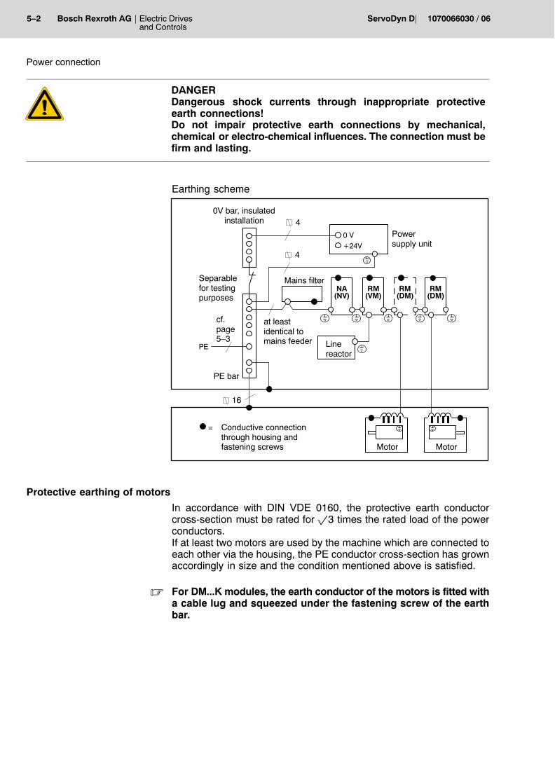
5.1 Earthing
CAUTIONInverter modules may only be operated with an earthed neutralsystem.Systems not directly earthed (IT protective system) must not beused for operation, as air clearances and leakage paths in the mo-dule may be overloaded.Operation at asymmetrical mains systems (TT protective system,one mains phase is earthed) is not permissible!
DIN VDE 0100-300 defines mains systems subject to their type of earthconnection.Accordingly, in an IT protective system, all active parts are separatedfrom earth, or one point is connected to earth via a resistor.The exposed conductive parts of an electrical system are eitherD earthed separately, orD earthed jointly, orD jointly connected to the system earth.
. Please note the information on earthing in the ServoDyn D EMCmanual, for part no. refer to page 5�3.
Protective earthing of inverters
DANGEROUS ELECTRICAL VOLTAGEThe only permissible protective measure in accordance withEN 50 178 is a protective earth connection.The protective conductor must at least have the same area as themains feeder.Earthing only one end of the DC link when operating by means ofan isolating transformer is prohibited!
Earth connections in the switch cabinet must be designed in the form ofa grid mesh.The module housing and mounting plate of the switch cabinet must beearthed. The connection between the line filter and the supply moduleshould be as short as possible.The protective earth cross-section must at least correspond to thecross-section of the line feeder of the supply module.
5�2 Electric Drivesand Controls
Bosch Rexroth AG ServoDyn D 1070066030 / 06
Power connection
DANGERDangerous shock currents through inappropriate protectiveearth connections!Do not impair protective earth connections by mechanical,chemical or electro-chemical influences. The connection must befirm and lasting.
In accordance with DIN VDE 0160, the protective earth conductorcross-section must be rated for �3 times the rated load of the powerconductors.If at least two motors are used by the machine which are connected toeach other via the housing, the PE conductor cross-section has grownaccordingly in size and the condition mentioned above is satisfied.
. For DM...K modules, the earth conductor of the motors is fitted witha cable lug and squeezed under the fastening screw of the earthbar.
Electric Drivesand Controls
5�3Bosch Rexroth AGServoDyn D1070066030 / 06
Power connection
PE bar
The cross-section of the PE bar and mounting plate earth conductormust be selected one size bigger than the line feeder of the supply mo-dule.
24 V power supply unit
The PE connection and the secondary circuit earthing (non-isolated)must be designed in accordance with the secondary current, but musthave a cross-section of at least 1.5 mm2.
0 V bar
The 0V bar must have an insulated structure and may be earthed in asingle point only. This measure is designed to avoid 24V operating currents in the earthand shield connections.
5.2 Electromagnetic compatibility (EMC)
. Please note the information given in the ServoDyn D EMC manual:
Language Part no.
German 1070 066 072
English 1070 066 074
French 1070 066 075
Italian 1070 066 076
5�4 Electric Drivesand Controls
Bosch Rexroth AG ServoDyn D 1070066030 / 06
Power connection
5.3 Earth-leakage circuit-breaker
Inverters incorporate switched power units which are always asso-ciated with capacitive leakage currents against earth. The leakage cur-rents may depend on the number of inverters, the earthing conditionsas well as the design and length of motor power cables.
Mains filters and shielded cables used to improve the electromagneticcompatibility (EMC) increase the leakage currents further. For this rea-son, no earth-leakage circuit-breakers with nominal leakage currents ofless than 300 mA may be used.
DANGEROUS ELECTRICAL VOLTAGEPersonnel protection is only guaranteed if earth-leakage circuit-breakers with nominal leakage currents of less than 30 mA areused.
. Inductors and/or capacitors present in the electric circuit may leadto spurious trips. If radio interference suppression filters are used,spurious trips can only be avoided by installing an isolating trans-former.
DANGEROUS ELECTRICAL VOLTAGEIf a pulse power current sensitive e.l.c.b. type A in accordancewith IEC-755 (VDE 0664) is used, its protective function is notguaranteed for inverters with a 3-phase mains connection (B6 cir-cuit).
The protection of all electrical components connected together with in-verters with a 3-phase mains connection to a pulse power current sensi-tive e.l.c.b. may be adversely affected.Therefore, you should either install an isolating transformer with a pro-tective device and earthing in the mains feeder, or use a universal cur-rent sensitive e.l.c.b. type B which also provides safety disconnection inthe event of DC leakage currents.
Electric Drivesand Controls
5�5Bosch Rexroth AGServoDyn D1070066030 / 06
Power connection
5.4 Mains supply
DANGEROUS ELECTRICAL VOLTAGEThe only permissible protective measure in accordance withEN 50 178 is a protective earth connection.The protective conductor must at least have the same area as themains feeder.Earthing only one end of the DC link when operating by means ofan isolating transformer is prohibited!
CAUTIONInverter modules may only be operated with an earthed neutralsystem.Systems not directly earthed (IT protective system) must not beused for operation, as air clearances and leakage paths in the mo-dule may be overloaded.Operation at asymmetrical mains systems (TT protective system,one mains phase is earthed) is not permissible!
The mains supply is connected directly to the NV line wiring module orthe NAA mains connection module via a mains filter.
D Supply voltage U = 400...460 V �10 %, 48...62 HzD Voltage drop between no-load and full-load DU = max. 5 %D The power electronics are excluded from the permitted total system
voltage dip for max. 10 ms required under EN 60204.In the event of a power failure, the drive is switched off, and an alarmis issued. For measures to be taken, refer to section 8.3.
D Voltage peaks: Between conductors � 1 kVConductor to ground � 4 kV
D The lightning protector which limits the transient overvoltage to 4 kVis a prerequisite in the sub-distribution. All air clearances and leak-age paths are designed for 4 kV (conductor to ground impulse with-stand voltage).
D The power connection is designed in accordance with the require-ments laid down in overvoltage category 3.
5�6 Electric Drivesand Controls
Bosch Rexroth AG ServoDyn D 1070066030 / 06
Power connection
Autotransformer
If the actual mains voltage is not identical with the specified supply volt-age, an isolating transformer or an autotransformer with the followingspecifications may be used:
3-phase autotrans-former to UL standardfor inverter input
Short-circuit voltage uk 1.5 % 1.5 % 1.0 % 0.8 % 0.8 %
Protection standard IP 00
Insulation class H/40
5.4.1 Connection of VMA..KB, VMA..KE (with ballast switch)
Supply modules with ballast switch are connected via the NV line wiringmodule and a mains filter.NV modules with an integrated mains filter comply with radio interfer-ence limit class A in accordance with EN 55011 (VDE 0875).
. UL class 1 power cables (e.g. UL Style 1007 or 1569 on mains side,H05: U0/U: 300/500 V) and a UL/CSA recognized ballast resistorhave to be used for UL/CSA-certified drive inverters.This is to ensure that the entire system meets the UL/CSA require-ments.
CAUTIONIn order to protect the VMA..K from damage, a mains filter mayonly be installed between the mains contactor and the inverter.
Electric Drivesand Controls
5�7Bosch Rexroth AGServoDyn D1070066030 / 06
Power connection
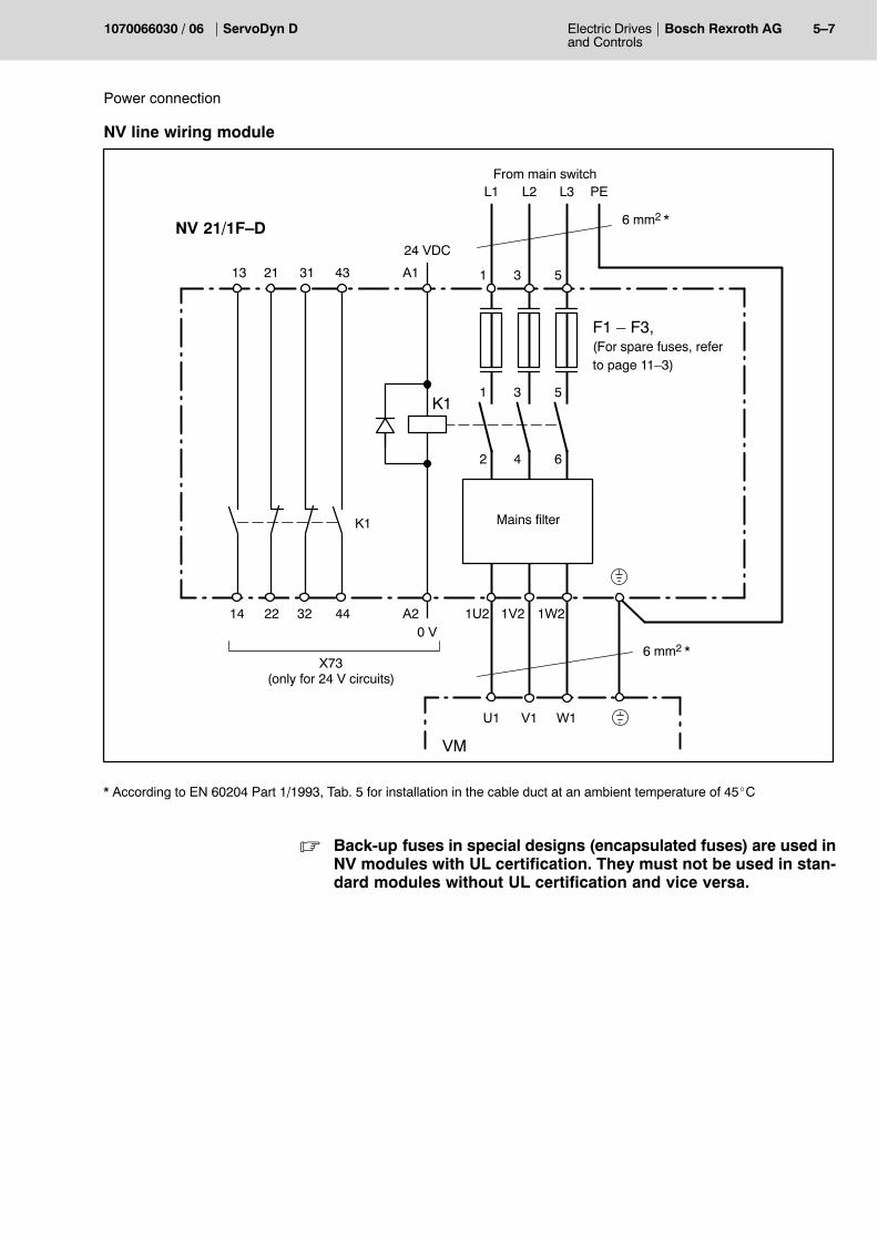
NV line wiring module
F1 � F3,(For spare fuses, referto page 11�3)
From main switch
6 mm2 *
NV 21/1F�D
Mains filter
K1
A2
A1
14 22
21
32
31
44
43
1W21V21U2
531
L1 L2 L3 PE
W1V1U1
0 V
24 VDC
13
K1
531
642
6 mm2 *
VM
X73(only for 24 V circuits)
* According to EN 60204 Part 1/1993, Tab. 5 for installation in the cable duct at an ambient temperature of 45_C
. Back-up fuses in special designs (encapsulated fuses) are used inNV modules with UL certification. They must not be used in stan-dard modules without UL certification and vice versa.
5�8 Electric Drivesand Controls
Bosch Rexroth AG ServoDyn D 1070066030 / 06
Power connection
5.4.2 Connection of VMA..KR, VMA..B,C,D and VMW..F (with current regeneration)
Supply modules with current regeneration have to be connected via themains filter, line reactor NE and the mains connection module NAA.
. UL class 1 power cables (e.g. UL Style 1007 or 1569 on mains side,H05: U0/U: 300/500 V) have to be used for UL/CSA-certified driveinverters.This is to ensure that the entire system meets the UL/CSA require-ments.
External mains filter
A mains filter in the mains supply cable must be provided so that limitclass A (B on request) for radio interference can be complied with inaccordance with EN 55 011 (VDE 0875). Some NAA modules are op-tionally available with an integrated mains filter.Furthermore, a mains connection module with an additional filter shouldbe selected for connection to a public network which contains an addi-tional filter with symmetric effect and provides interference suppressionfor the mains current elements at switching frequency.
The external filter size must correspond to the supply module output.
. Due to the mains pollution caused by shielded motor cables, thepermissible length of the motor cables is limited depending on themains filter used (also refer to Configuration manual, part no. onpage 1�7).
L1 L2 L3
U1 V1 W1
U2 V2 W2
PE
Mains filteroption
NAA..
L1 L2 L3
L1 L2 L3LineLoad
Electric Drivesand Controls
5�9Bosch Rexroth AGServoDyn D1070066030 / 06
Power connection
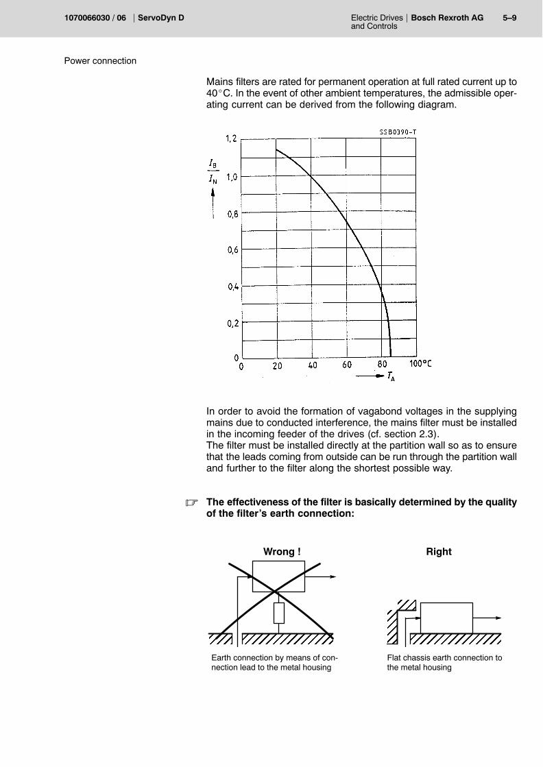
Mains filters are rated for permanent operation at full rated current up to40_C. In the event of other ambient temperatures, the admissible oper-ating current can be derived from the following diagram.
In order to avoid the formation of vagabond voltages in the supplyingmains due to conducted interference, the mains filter must be installedin the incoming feeder of the drives (cf. section 2.3).The filter must be installed directly at the partition wall so as to ensurethat the leads coming from outside can be run through the partition walland further to the filter along the shortest possible way.
. The effectiveness of the filter is basically determined by the qualityof the filter�s earth connection:
ÉÉÉÉÉÉÉÉÉÉ ÉÉÉÉÉÉÉEarth connection by means of con-nection lead to the metal housing
Flat chassis earth connection tothe metal housing
ÉÉÉÉÉÉ
ÉÉÉÉ
Wrong ! Right
5�10 Electric Drivesand Controls
Bosch Rexroth AG ServoDyn D 1070066030 / 06
Power connection
NAA 21, NAA 35 and NAA 70 mains connection modules
NAA 21 with integrated mains filter, optional for NAA 35. Another op-tional item is an integrated additional filter for connection to the publicnetwork.
F1 � F3,For type, refer to in-formation given below
From main switch
NAA 21: 4 mm2 *NAA 35: 10 mm2
NAA 70: 25 mm2
Mains filteroption
(standard in NAA 21)
22
21
32
31
44
43
W2V2U2
531
L1 L2 L3 PE
X 74
531
642
NAA 21: 4 mm2 * NAA 35: 10 mm2
NAA 70: 25 mm2
Control line toVM, X32
R1 � R3
Additional filter option
Contactor controland
synchronization
via line reactor NEto VM
K2
K2 K1
W1V1U1
* According to EN 60204 Part 1/1993, Tab. 5 for installation in the cable duct at an ambient temperature of 45_C
Fuses: NAA 21, UL-certified: 3 x FERRAZ encapsulated fuse, very quick acting, 50 A/690 VNAA 35, standard: 3 x Jean Müller M00üf1, very quick acting, 63 A/660 V
UL-certified: 3 x FERRAZ encapsulated fuse, very quick acting, 63 A/690 VNAA 70, standard: 3 x Jean Müller M00üf1, very quick acting, 100 A/660 V
UL-certified: 3 x FERRAZ encapsulated fuse, very quick acting, 100 A/690 V(For part numbers, refer to page 11�3)
Electric Drivesand Controls
5�11Bosch Rexroth AGServoDyn D1070066030 / 06
Power connection
Power connection to VMA..KR and VMA..B,C
1U1
1V1
1W1
L1 L2 L3
U1 V1 W1
U2 V2 W2
PE
U2 W2V2
Linereactor
NE
U1 W1V1
Mains filteroption
NAA..
VMA..KRVMA..B,C DM..A,
B,D(with currentregeneration)
DM..K
Motor Motor
Between the NAA mains connection module and the supply modulewith current regeneration a line reactor NE is installed.
The supply module must be considered when choosing the size of theline reactor (refer to manual �Configuration�). The line reactor is equipped with cable ends which can be shortened tothe required length. We recommend using plug connectors for terminalconnection.
CAUTIONA reversed phase sequence or winding direction of a line reactorwill destroy the mains connection module.Please ensure proper wiring.
5�12 Electric Drivesand Controls
Bosch Rexroth AG ServoDyn D 1070066030 / 06
Power connection
NAA 90 mains connection module
F1 � F3,For type, refer to in-formation given below
From main switch
25 mm2 *
NAA 90..-D
22
21
32
31
44
43
1V22U21U2
531
L1 L2 L3 PE
X 74
531
642
35 mm2 *
Control line toVM X32
R1 � R3
Additional filter(only in NAA 90/2.. -D)
via line reactor NE toVMA 90D
K2
K2 K1
2W21W22V2
Contactor controland
synchronization
* According to EN 60204 Part 1/1993, Tab. 5 for installation in the cable duct at an ambient temperature of 45_C
Fuses: NAA 90: 3 x Jean Müller M00üf1, very quick acting, 125 A/660 V(For part numbers, refer to page 11�3)
Electric Drivesand Controls
5�13Bosch Rexroth AGServoDyn D1070066030 / 06
Power connection
Power connection to VMA 90D
2U1
2V1
2W1
L1 L2 L3
U1 V1 W1
U2 W2V2
2 Xline reactor
NE 70A
U1 W1V1
Mains filteroption
NAA 90
VMA..90D DM..A,B,D(with current
regeneration)
DM..K
Motor Motor1U
11V
11W
1U2 W2V2
U1 W1V1
2W2
1W2
2V2
1V2
2U2
1U2
PE
The NE 70 line reactors are connected between the mains connectionmodule and the supply module with current regeneration.
CAUTIONA reversed phase sequence or winding direction of a line reactorwill destroy the mains connection module.Please ensure proper wiring.
5�14 Electric Drivesand Controls
Bosch Rexroth AG ServoDyn D 1070066030 / 06
Power connection
NAA 180 mains connection module
F1 � F3,For type, refer to in-formation given below
From main switch
14
13
22
21 W1V1U1
L1 L2 L3 PE
X 73
531
642
90 mm2 *
Control line toVM, X32
R1 � R3
K2
K1
K1
N
L
0 VAC
K2
X 20
35 mm2 *
1V22U21U2
via line reactor NE 180 with filter capacitor toVMW 180F
2W21W22V2
230 V (110 V)50/60 Hz
Contactorcontrol
andsynchroniz-
ation
K1
* According to EN 60204 Part 1/1993, Tab. 5 for installation in the cable duct at an ambient temperature of 45_C
Fuses: NAA 180: 3 x Jean Müller M00üf1, very quick acting, 250 A/660 V(For part numbers, refer to page 11�3)
Electric Drivesand Controls
5�15Bosch Rexroth AGServoDyn D1070066030 / 06
Power connection
Power connection to VMW 180F
1U1
2U1
1V1
L1 L2 L3
U1 V1 W1
1U2
PE
Line reactor NE 180
Mains filteroption
VMW 180F(with currentregeneration)
1W1
2V1
2W1
U11
NAA 180 DMW290F
Motor
2W2
1W2
2V2
1V2
2U2
1U2
2U2
1V2
2V2
1W2
2W2
U12 V11
V12
W11
W12
U21
U22
V21
V22
W21
W22
Filter capacitor
U3V3
W3
4 mm2
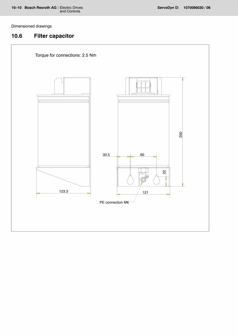
The NE 180 line reactor is installed between the mains connection mo-dule and the supply module with current regeneration. A filter capacitor is additionally required. Due to the high surface tem-perature of the line reactor, the distance between the filter capacitor andthe line reactor must be 1 m min. Cable length 2 m max.
CAUTIONA reversed phase sequence or winding direction of a line reactorwill destroy the mains connection module.Please ensure proper wiring.
5�16 Electric Drivesand Controls
Bosch Rexroth AG ServoDyn D 1070066030 / 06
Power connection
5.5 Ballast resistor connection
Without UL/CSA requirements:The external ballast resistor EB-TA with 10 W/1.5 kW is connected toterminals R+, R of the VMA 21KE supply module which is not UL/CSAlisted.
Operation in compliance with UL/CSA:An external UL/CSA recognized ballast resistor has to be connected toterminals R+, R of the UL/CSA listed VMA 21KE supply module.
Required data:Value: 10 W ± 10%Voltage: max. 800 VPower: P ≥ 1200 WEnergy: P ≥ 60 kWs
Potential suppliers: Danotherm, Fritzlen, Koch
CAUTIONThe power supply module monitors the ballast resistor load. Bal-last resistors could be damaged, if they are dimensioned with toosmall power and energy.
U1 V1 W1
Ballast resistor connection
R+ R
VMA..KE
D Conductor cross-section: 2.5 mm2
D Cable length: max. 10 m
. UL class 1 power cables (e.g. UL Style 1007 or 1569 on mains side,H05: U0/U: 300/500 V) have to be used for UL/CSA-certified driveinverters.
Electric Drivesand Controls
5�17Bosch Rexroth AGServoDyn D1070066030 / 06
Power connection
5.6 24 V supply
The supply modules require a 24 V supply from an external 24 VDC loadpower supply module in accordance with EN 61 131 (20.4 � 28.8 V). Astabilized power supply unit is not required.The input terminals are protected by miniature fuse F1 20 A/32 V.Spare fuse, part no. 1070 917 667The 0 VPWR connection is internally floating against ground. If the 0 Vare to be grounded, the ground connection has to be made, e.g., at theexternal 24 V power supply unit.
DANGEROUS ELECTRICAL VOLTAGEThe 24 VDC must satisfy the �safety separation� requirements. The requirements in accordance with the overvoltage category IIIshould be noted on the primary side!
In the inverters, the extra-low-voltage circuits are safety-separated fromthe mains circuit (safety separation to EN 50178).
CAUTIONContact system destroyed!Connector X30 may only be inserted or removed while the unit isdisconnected from power. Furthermore, the connection screwshave to be firmly tightened. Use a screw driver with a blade size0.6 x 3.5 for this purpose.
DANGERThe drives coast to a standstill if the 24 V supply is interrupted!This can be avoided by taking one of the following measures:D use a buffered 24 V power supply unit (no 100% safety)D plug braking of the motors with KSB (plug braking) moduleD use motors with a holding brake.
The 24 VDC supplied to the VM are passed on:D via the 24V cross-connection X820 to the logic and driver supply of
the inverter modules and the fan supply of the backplane modulesD via the 24V outputs X331/X332 for the supply of all module outputs
of the axis modules.
5�18 Electric Drivesand Controls
Bosch Rexroth AG ServoDyn D 1070066030 / 06
Power connection
Due to the cross-connection to the axis modules, the number of in-verters that can be connected is limited:D maximally 9 axes per VMD maximally 14 A power input (24 VDC) per VM
Module type Backplane module 24 VDC current input
VMA 21K � 1.0 A
VMA 21KR � 2.1 A
VMA 35B RMB/VM 2.3 A
VMA 70C RMC/VM 2.7 A
VMA 90D RMD/VM 3.1 A
VMW 180F � 2.5 A
DMA 4K � 0.89 A
DMA 8K � 0.89 A
DMA 15K � 0.89 A
DMA 30K � 1.03 A
DMA 45 K � 1.4 A
DMA 4A RMA/DM8 1.0 A
DMA 8A RMA/DM8 1.14 A
DMA 15A RMA/DM30 1.14 A
DMA 30A RMA/DM30 1.23 A
DMA 45A RMA/DM45 1.32 A
DMA 85B RMB/DM 1.35 A
DMA 140D RMD/DM 1.58 A
DMW 290F � 2.5 A
Total of one drive set max. 14 A
Electric Drivesand Controls
5�19Bosch Rexroth AGServoDyn D1070066030 / 06
Power connection
5.7 Motor connection
DANGEROUS ELECTRICAL VOLTAGEDue to the permanent magnet excitation, the power connectorcarries a hazardous high voltage if the rotor is rotating and themotor is not electrically connected! The unit must be completely de-energized and halted before com-mencing any connection or installation work.
Motor cablesWe recommend using prefabricated Bosch motor cables for the SF andSR servo motors. Depending on the individual case, these cables areavailable asD Standard cables, shieldedD Standard cables, unshieldedD UL power cable
. UL class 1 power cables (e.g. UL Style 1510 on motor side,H07: U0/U: 600/1000 V) have to be used for UL/CSA-certified driveinverters. This is to ensure that the entire system meets the UL/CSA requirements.
CAUTIONDamage to cables due to inadmissible movements.Please note the technical data of the cables specified in the �Con-figuration manual�, part no. on page 1�7.
Cable bushing (metal flange)
For cable bushings, e.g. leading into the switch cabinet, a metal flangemay be used in connection with a cable extension and a coupling. Theconnector housing is clamped and sealed to IP 65 when installed.Flange: Zinc diecasting, nickel-platedGasket: Viton, black
Gasket
Clamp
Flange
Housing/Cabinet
Sealing ring
5.5
∅40
Mounting hole for con-nector size 1
5�20 Electric Drivesand Controls
Bosch Rexroth AG ServoDyn D 1070066030 / 06
Power connection
5.7.1 SF, SR servo motors power and brake connection
CAUTIONDamages at the inverter or encoder by inserting or removingplug-in connections on live systems!Switch the drive off beforehand.
. Please note that unshielded motor cables may inject voltages intoother cables laid in parallel due to capacitive injection mechan-isms.Noticeable voltages are particularly injected in unused brakecores. In accordance with IEC 1201, the line capacitance is notsufficient to generate lethal voltages (at a cable length of 100 m ap-prox. 15 nF between cores, a dangerous value would be 28 nF at400 V). Insulate the open ends of the brake cores.If cables are laid in parallel, injection is approx. 10 times lower. Shielded motor cables do not produce injections.
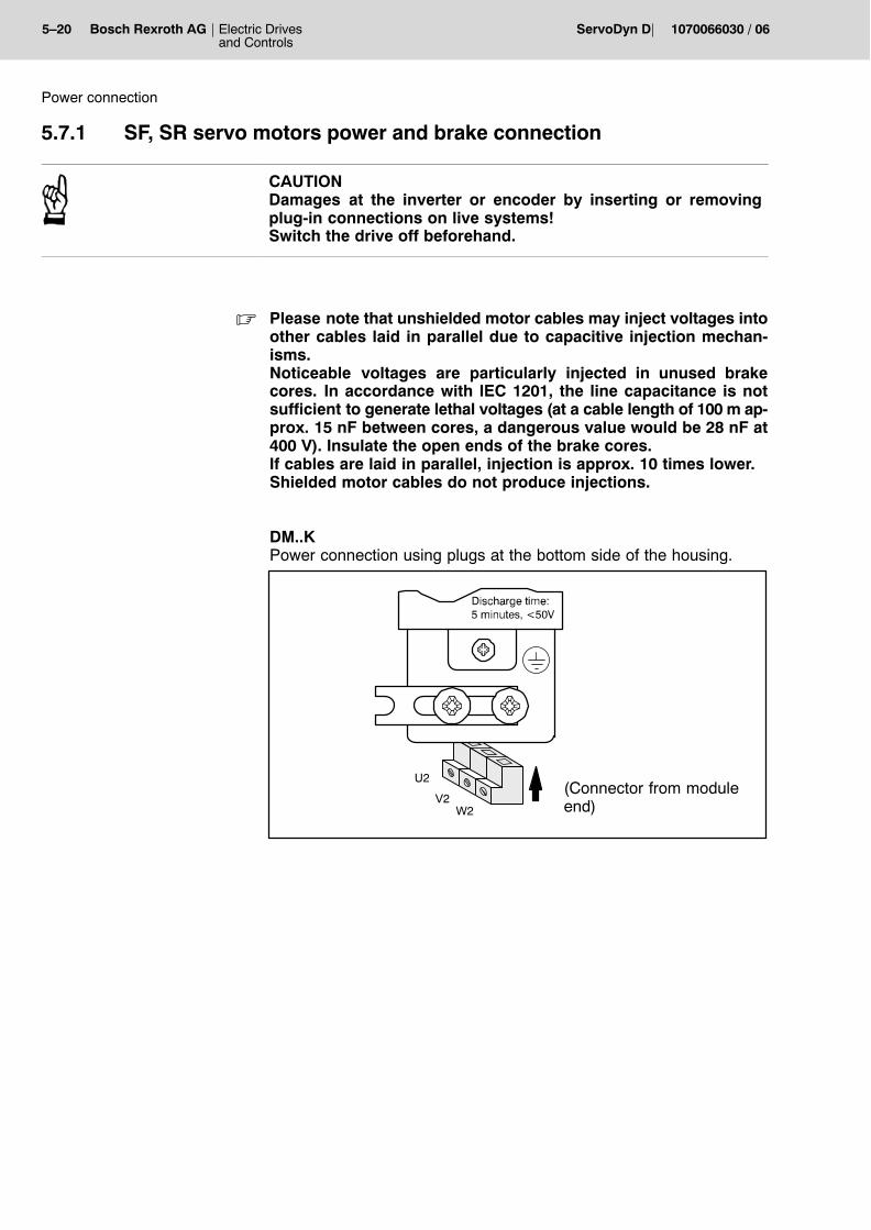
DM..KPower connection using plugs at the bottom side of the housing.
U2
V2W2
(Connector from moduleend)
Electric Drivesand Controls
5�21Bosch Rexroth AGServoDyn D1070066030 / 06
Power connection
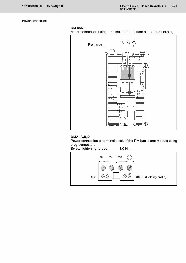
DM 45KMotor connection using terminals at the bottom side of the housing.
U2 V2 W2Front side
DMA..A,B,D Power connection to terminal block of the RM backplane module usingplug connectors.Screw tightening torque: 3.0 Nm
U2 V2 W2
X68 X69 (Holding brake)
5�22 Electric Drivesand Controls
Bosch Rexroth AG ServoDyn D 1070066030 / 06
Power connection
DMW 290F Power connection to terminal block at the bottom side using plug con-nectors.Screw tightening torque: 12.0 Nm
Rated voltage of the motor power cables:U0/U = 600/1000 VAC.
DANGEROUS ELECTRICAL VOLTAGEMotor leads and brake leads are led in a multi-conductor cable.The cores of the brake lead must have the same insulation as thecores of the motor lead (U0/U= 600/1000 VAC).If no holding brake is connected, the open ends of the brake leadmust be insulated!
. For connection cross-sections and more information on the leads,please refer to the �Configuration� and �SF, SR servo motors�manuals.
5�24 Electric Drivesand Controls
Bosch Rexroth AG ServoDyn D 1070066030 / 06
Power connection
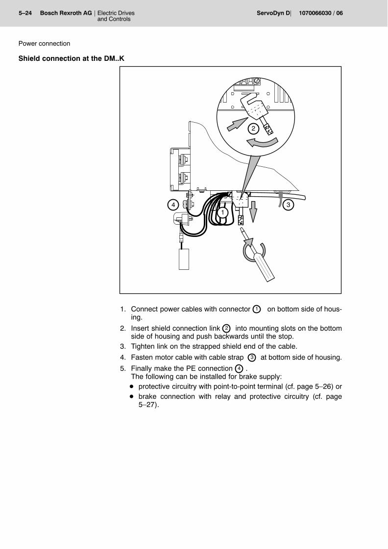
Shield connection at the DM..K
ÎÎÎÎ
ÂÂÂÂ
2
34
ÂÂÂÂ
1
1. Connect power cables with connector 1 on bottom side of hous-ing.
2. Insert shield connection link 2 into mounting slots on the bottomside of housing and push backwards until the stop.
3. Tighten link on the strapped shield end of the cable.
4. Fasten motor cable with cable strap 3 at bottom side of housing.
5. Finally make the PE connection 4 .The following can be installed for brake supply:D protective circuitry with point-to-point terminal (cf. page 5�26) orD brake connection with relay and protective circuitry (cf. page
5�27).
Electric Drivesand Controls
5�25Bosch Rexroth AGServoDyn D1070066030 / 06
Power connection
Shield connection at the DM..A,B,D,F
A shield connector has to be additionally fitted to the backplane modulein order to connect a shielded power cable.For part numbers of the conductor areas, cf. page 11�1.The cable must be fastened to the module using a metallic cable strap,e.g. metallic cable strap made by Rittal:
125 x 4.6 (No. SZ 2598.125) or200 x 4.6 (No. SZ 2598.200).
W
3Nm
0.6N
m
X68 X68
U V
Shield connectorfor power cable
Shield con-nector for brakecable
5�26 Electric Drivesand Controls
Bosch Rexroth AG ServoDyn D 1070066030 / 06
Power connection
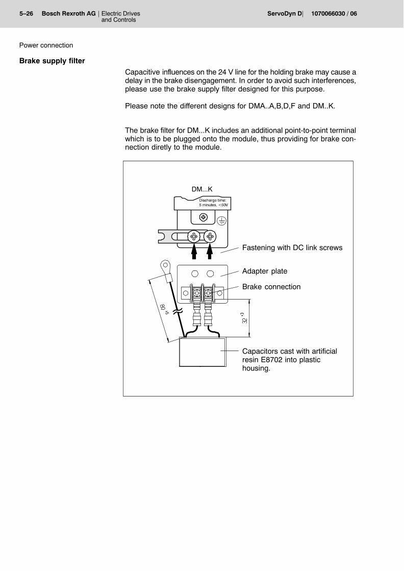
Brake supply filter
Capacitive influences on the 24 V line for the holding brake may cause adelay in the brake disengagement. In order to avoid such interferences,please use the brake supply filter designed for this purpose.
Please note the different designs for DMA..A,B,D,F and DM..K.
The brake filter for DM...K includes an additional point-to-point terminalwhich is to be plugged onto the module, thus providing for brake con-nection diretly to the module.
Adapter plate
Capacitors cast with artificialresin E8702 into plastichousing.
DM...K
Fastening with DC link screws
Brake connection
Electric Drivesand Controls
5�27Bosch Rexroth AGServoDyn D1070066030 / 06
Power connection
MBC brake connection with relay and protective circuitry
These accessories eliminate interference and facilitate brake control,because they contain an additional relay.
Active with +24 V.A1: Holding brake control signal from DM, X34.2 (Out3)A2: 0 V from VM, X332
. For UL-conformant drive installations:If A1, A2 are not controlled via the DM, the voltage supply mustcomply with UL Class II.
13, 14 Auxiliary contactFreely available auxiliary contact of the control relay.
+, � Holding brakeConnection of motor brake line.
5�28 Electric Drivesand Controls
Bosch Rexroth AG ServoDyn D 1070066030 / 06
Power connection
X40 24 V, 0 V Voltage supply
24 VDC voltage supply of the control relay.The 24 V are looped through to the next module via the 2nd pair of ter-minals.
STA LED, green
The LED is on if the holding brake of the motor has been vented, i.e.when control is active.
S Key
The brake can be vented using the S key if no external control signal ispresent.
Electric Drivesand Controls
5�29Bosch Rexroth AGServoDyn D1070066030 / 06
Power connection
5.7.2 DU asynchronous motor power connection
Motor endThe following electrical connections are made in the terminal box:D PowerD External fanD Holding brake option
Cable entry is through two heavy-gauge conduit threads.The terminal box is located on the top as standard and can be turned by4 x 90_. Circuit diagram on the terminal box lid.
Module endDMA..A,B,D:Power connection with plug connectors at the RM backplane moduleterminal block. Screw tightening torque 3.0 Nm
DM..K:Power connection using plugs at the bottom side of the housing.
W2 U2 V2
U1 V1 W1
Externalfan
2U1
2V1
2W1
U2 V2 W2
3 x 400...415 V�10 %,
50�60 Hz
DU asynchronousmotor
RM / DM...K
2U2�
2V2�
2W2
1 2
Holdingbrakeoption
PE
24 V DC�10 %
Star connection, to be used for motors size 90
D connection, to be used for motors size 100 ... 160
CAUTIONThe contacts of the motor contactor may weld together if openedunder excessive load!The motor contactor may only be opened when n = 0 and enablinghas been cancelled.
5�30 Electric Drivesand Controls
Bosch Rexroth AG ServoDyn D 1070066030 / 06
Power connection
Notes:
Electric Drivesand Controls
6�1Bosch Rexroth AGServoDyn D1070066030 / 06
VMA..KB, VMA..KE supply module control connections
6 Control connections on supply modules
6.1 VMA..KB, VMA..KE supply module control connections (with ballast switch)
X8
U1 V1 W1
..
...... 1
0X820
X810: Signal cross-connection
X820: 24 V cross-connection
X
..
..
..
..312
X........
331..
..X ..
..
..
..
332
..
..
F1
H1: 7-segment display for statusmessages and error messages
X312
NAF relay8 �7 �6 �5 �4 � MT3 � NO2 � NH1 � ZT
X30 2 � 0 VPWR
1 � 24 VPWR
Fuse F120A/32V(1 x 1070 917 667)
Earthing bolt M6Earth bar connection
d.c. link connection
H1
20A32V
1
12
X331: 1...12 � 24 Vout
X332: 1...12 � 0 Vout
BTB relay
Mains connection Ballast switch connection
R+ R
6�2 Electric Drivesand Controls
Bosch Rexroth AG ServoDyn D 1070066030 / 06
VMA..KB, VMA..KE supply module control connections
6.1.1 Terminal strips
Terminal strip X30
2
1X30
24 VPWR
0 VPWRVM
X30.1/2 24VPWR, 0VPWR 24 V module supply (power)
Power supply to the module is provided by an external 24 VDC loadpower supply unit according to section 5.6.
Terminal strip X312
VM
X312
3 NO
8
7
2
4 MT
1
+24 VNAFrelay
NH
BTB
6
5+24 V
BTBrelay
NAF
ZT
X312.1 ZT Dead-man�s key
Optocoupler input for dead-man�s key,active with +24VDC (16...30V).
Dead man�s key without 2-channel evaluation, i.e. RSU functionality notpossible.
X312.2 NH Emergency-Stop (drive halt)
Optocoupler input for the Emergency-Stop function,active with 0VDC.If this signal is LOW, the motor is halted as defined in parameterP-0-0004:D within the shortest time possible (S-0-0138)D drive-controlled via ramp S-0-0260
Electric Drivesand Controls
6�3Bosch Rexroth AGServoDyn D1070066030 / 06
VMA..KB, VMA..KE supply module control connections
D setpoint-controlled by masterD drive-controlled via ramp P-0-0260 (for SERCOS interface only).
When halted, the torque is removed from all motors.For connection, cf. page 6�5.
X312.3 NO Normal operating mode
Optocoupler input, active with +24VDC (16...30V).
X312.3 is to be permanently wired to 24V to specify normal mode asfixed mode. Maximum speed monitoring of the drives is thus always ac-tive.For connection, cf. page 6�5.No 2-channel special operating mode, i.e. RSU functionality not poss-ible.
X312.4 MT Measuring probe input
Optocoupler input for the measuring probe of the machine, active with+24V.Can be used as a setpoint interface in connection with SERCOS inter-face only.The signal is transmitted to the DMs through the X810 module cross-connection. The signal propagation delay between the measuring probeand the axis in question is < 5 ms.
X312.5/6 BTB Ready
Floating relay contact. Max. load 24 V/1000mA.The contact closes when:D 24V module supply activeD no error in VMD d.c. link is active
In the occurrence of the following malfunctions, the BTB contact is im-mediately opened, the VM output stage and the output stages of theaxes are inhibited:D d.c. link undervoltage (< 400 V)D d.c. link overvoltage (> 750 V)D ballast switch overloadD power supply unit faultD module overtemperatureD ambient overtemperature
The BTB contact is a group error message. It must be evaluated by thestart logic of the mains contactor in order to prevent that mains voltage isstill active in the event of an error although the VM is switched off(cf. page 6�5).
6�4 Electric Drivesand Controls
Bosch Rexroth AG ServoDyn D 1070066030 / 06
VMA..KB, VMA..KE supply module control connections
X312.7/8 NAF Mains failure
Floating relay contact. Max. load 30 VDC/1000 mA.The contact immediately opens in the event of:D mains failure
NAF can be evaluated as a warning, e.g. for further processing by a PLC.
Terminal strips X331, X332
VM..K
X331
10
9
8
3
12
54
7
6
1112
VM..K
X332
10
9
8
3
12
54
7
6
1112
24 VOut 0 VOut
X331 24 VOut Module supply
X332 0 VOut Module supply
X331, X332 are the reference potential of the X312 terminal block andserve for the supply of the interface inputs and outputs at the drive mod-ules.X331, X332 must be wired to:all three-phase modules X06.9: 24 VIn
X06.10: 0 VIn
. X331 can be loaded with 3 A max. If higher loads are applied, thecurrent limitation becomes active, and voltage breaks down.
X810 plug-in connection
Signal cross-connection of all drive modules.The ribbon cable of the adjoining module on the right is inserted into con-nector X810.
Electric Drivesand Controls
6�5Bosch Rexroth AGServoDyn D1070066030 / 06
VMA..KB, VMA..KE supply module control connections
X820 plug-in connection
24V cross-connection of all drive modules.For 24V supply of the drive modules, the cable of the adjoining moduleon the right is inserted into connector X820.
CAUTIONContact system destroyed!Connector X820 of the 24 V cross-link may only be inserted or re-moved while the unit is disconnected from power.
6.1.2 Start logically linked to EMERGENCY-STOP switchgear
DANGERThe VM should be isolated from the supplying mains in the eventof a fault!For this purpose, switch the BTB contact of the VM unit into thelatching function of the K1 mains contactor.
6�6 Electric Drivesand Controls
Bosch Rexroth AG ServoDyn D 1070066030 / 06
VMA..KB, VMA..KE supply module control connections
Start logically linked for inverters with analog interface, Motion Control, CAN bus,PROFIBUS-DP
24�VDC
Drive ONK1
Mains contactor K1
0 V
A1 (NV..�D)
A2 (NV..�D)
13 (NV..�D)
14 (NV..�D)
43 (NV..�D)
44 (NV..�D)
K1
DriveOFF
Emergency-Stop switchgear
Ready
STA relay(axis 1...n)
NH, X312.2 (VM)
Control/PLC
FG, X06.3
FG
(Drive enable)
V1
EMERGENCY-STOP
BTB
X312.5 (VM)
X312.6 (VM)
. In case of EMERGENCY-STOP, inverters enabled with FG/FGI sig-nal �VM switched off with active control (F98)�.This message can be acknowledged by setting FG again.
Electric Drivesand Controls
6�7Bosch Rexroth AGServoDyn D1070066030 / 06
VMA..KB, VMA..KE supply module control connections
Start logically linked for inverters with SERCOS interface
FG, X06.3 (DM, drive without torque if not enabled)
V1
BTB
X312.5 (VM)
X312.6 (VM)
Drive ON
Mains contactor K1
DriveOFF
Control/PLC
EMERGENCY-STOP
. In case of EMERGENCY-STOP, inverters enabled with FG/FGI sig-nal �VM switched off with active control (F98)�.This message can be acknowledged with �Reset diagnostics class1�.
6�8 Electric Drivesand Controls
Bosch Rexroth AG ServoDyn D 1070066030 / 06
VMA..KR, VMA..B,C,D and VMW..F control connections
6.2 VMA..KR, VMA..B,C,D and VMW..F control connections (with current regeneration)
Figure shows VMA 35B, interface is identical for all modules
F1
20A32V
.
X8
X0
X34
X99
H1
RS 232 interface
U2 V2 W2
....
..
....
..
..
..
X27
AE FGI
..
...... 1
0X820
Reset
X810: Signal cross-connection
X820: 24 V cross-connection
Personality module
..
.....
X32
X
..
..
..
..312
X........
331
..
..
X........
332
..
..
X81
X820
0
D C
S1
X27: Slot for memory card
H1:7-segment display for statusmessages and error messages
2 � NH13 �4 � only in the5 � case of RSU*6 �7 � MT8
X312
1...12 � 24 VOut
1...12 � 0 VOut
X30
1 � 24 VPWR2 � 0 VPWR
24 V modulesupply
Fuse F1 20A/32V(1 x 1070 917 667)
S1:Power-off delayof internal enable signal
d.c. link test sockets (not with VMA..KR)
* RSU = redundant safety control
6
Hex switch 1,2,3, ... FTime [sec] 1,2,3, ... 15
d.c.�link
Electric Drivesand Controls
6�9Bosch Rexroth AGServoDyn D1070066030 / 06
VMA..KR, VMA..B,C,D and VMW..F control connections
6.2.1 Terminal strips
For wiring, see section 6.2.2 .
Terminal strip X06
VM
X06
10
9
8
3
STA
0 VIn
Supplyinputs/outputs
NH
1
2
5
4 NH 0V
24 VIn
7 AE
6 NO
+24 VSTArelay
ZT RSU functionality(refer to RSU manual)
X06.1/2 STA Status message
Floating relay contact. Max. load 24 V / 1000 mA.
The contact closes, if:D 24 V module supply activeD no error occurs in the VM
(central enable FGZ is disabled by overvoltage, undervoltage or byaxes standstill after Emergency-Stop)
D Temperature switch-off limit not exceededD d.c. link control is active
If an error occurs the STA contact is immediately opened, the VM outputstage and axes output stages are disabled and the mains contactors areswitched off.The STA contact is a group error message. It does not concern safetyand need not be evaluated.
6�10 Electric Drivesand Controls
Bosch Rexroth AG ServoDyn D 1070066030 / 06
VMA..KR, VMA..B,C,D and VMW..F control connections
X06.3/4 NH / NH 0V Emergency-Stop, channel 2
Optocoupler input for Emergency-Stop function, active with LOW level.
If NH (X06.3) is LOW (contact is open), all axes are halted as defined inparameter P-0-0004:D within the shortest time possibleD drive-controlled via ramp S-0-0260D setpoint-controlled by master
When halted, the torque is removed from all motors.For connection, cf. page 6�17.
X06.6 NO Normal operating mode7-segment display:
Optocoupler input, active with +24 V DC (16...30 V).
X06.6 is to be permanently wired to 24 V to specify normal mode as fixedmode. Maximum speed monitoring of the drives is thus always active.Upon LOW level, all drives are switched off and cannot be switched onagain before RESET has been activated.For connection, cf. page 6�17.
Changing over to �Set-up� special mode is only possible with the RSUoption. Refer to �RSU, Redundant safety monitoring� manual.
X06.7 AE Drive on / RESETDisplay by means of the �AE� and �FGI� LEDs
Optocoupler input to switch the drive on and to clear errors on the VM.Active with +24 V DC (16...30 V), both LEDs illuminate when the drive ison.For connection refer to page 6�17.
AE must be operated for at least 0.1s.An active error message is cleared if the error has been corrected. If sev-eral errors have occurred the error with the higher next priority is thendisplayed.The VM will be automatically activated if no more errors exist and theEmergency-Stop channels have not been interrupted:D The mains contactors in the NAA module are switched onD The d.c. link voltage controller is activatedD VM initiates central enable FGZD STA contact is closed.
The On key is controlled against manipulation. The On key is onlyswitched on by a positive edge if the Emergency-Stop channels remainuninterrupted.
Electric Drivesand Controls
6�11Bosch Rexroth AGServoDyn D1070066030 / 06
VMA..KR, VMA..B,C,D and VMW..F control connections
X06.9/10 24VIn, 0VIn Supply of the outputs
Input and output supply voltage at X06 and X34, to be connected to oneof the supply voltage outputs at the VM (X331, X332).
Terminal strip X30
1
2X30
24 VPWR
0 VPWR
VM
X30.1/2 24VPWR, 0VPWR 24 V module supply (Power)
Power supply to the module is provided by an external 24 VDC loadpower supply unit according to section 5.6.
Terminal strip X32
The mains connection module control cable is plugged into the X32 ter-minal strip. The mains connection module is thus connected to the VM.
6�12 Electric Drivesand Controls
Bosch Rexroth AG ServoDyn D 1070066030 / 06
VMA..KR, VMA..B,C,D and VMW..F control connections
Terminal strip X34
1
X343
4
5
6
2
Out 4 Overload
Out 3 Mains failure
Out 2 Excess temperature
Relay contact Out 1,currently unused
VM
X34.1 Out 4 Overload7-segment display:
Digital output +24 V.The output signal changes from +24 V to LOW level if the supply modulereaches its current limit or interrupts the d.c. link controller during supplyand/or regeneration. This can occur if:D maximum power Pmax > 140 % (rms) orD rated power PN > 100 %
CAUTIONIf overload occurs the VM could switch off the drives without delaydue to overcurrent (supply) or overvoltage (regeneration). The VM load should be immediately reduced.
Out 4 can be evaluated as a warning, e.g. for further processing in thePLC.
X34.2 Out 3 Mains failure7-segment display:
Digital output +24 V.The output signal changes from +24 V to LOW level, if UMains rms is <70 % for >3 ms, i.e. at least 2 phases in the supply mains have brokendown.
The power unit in the supply module is immediately disabled if an erroroccurs.
Electric Drivesand Controls
6�13Bosch Rexroth AGServoDyn D1070066030 / 06
VMA..KR, VMA..B,C,D and VMW..F control connections
CAUTIONIf mains failure occurs the VM could switch off the drives withoutdelay due to overcurrent (supply) or overvoltage (regeneration).The d.c. link must be immediately boosted (supply operation) orunloaded (regeneration operation).
Out 3 can be evaluated as a warning, e.g. for further processing in thePLC.Irrespective of this, the VM sends a warning to the axis modules via themodule cross-connection so that measures can be taken immediately toprovide d.c. link support.When the mains supply returns and �Drive On� is active, the power unit isenabled, and the DC link voltage control is resumed.
. In the case of a 1-phase mains failure (U4 display) the VM continuesto function. Power is reduced however to 66 %. The VM bridges frequent 1-phase short-term failures in this way.Overload can result from a long-term failure.
X34.3 Out 2 Excess temperature7-segment display: or
Digital output +24 V.The output signal changes from +24 V to LOW level if the prewarninglimit forD the heat sink temperature (U2) orD the ambient temperature (U3)is exceeded.When the switch-off limit is reached, the STA status relay is opened.
Prewarning limit Cut-off limit
Heat sink temperature >�75°C >�80°C
Ambient temperature >�45°C >�55°C
6�14 Electric Drivesand Controls
Bosch Rexroth AG ServoDyn D 1070066030 / 06
VMA..KR, VMA..B,C,D and VMW..F control connections
Terminal strip X312
4
3
2
1
X312
VM ZT 0V (only with RSU)
NH1
SO (only with RSU)
SO 0V (only with RSU)
ST-S (only with RSU)
ST-R (only with RSU)
MT
8
7
6
5
. For a description of those terminals which are only needed for theRSU option, please refer to the �RSU, Redundant safety monitor-ing� manual.
X312.2 NH1 Emergency-stop 1, channel 1
Optocoupler input for the Emergency-Stop function,active with LOW level.
If LOW level is present at X312.2, all connected inverters are braked. For connection, cf. page 6�17.
X312.7 MT Measuring probe input
Optocoupler input, active with +24 V.
Input for the machine measuring probe. The signal is transmitted to the DMs via the X810 module cross-connec-tion. The measuring signal propagation delay to the appropriate axis is <5 ms.
Electric Drivesand Controls
6�15Bosch Rexroth AGServoDyn D1070066030 / 06
VMA..KR, VMA..B,C,D and VMW..F control connections
Terminal strips X331, X332
VM
X331
10
9
8
3
12
54
7
6
1112
VM
X332
10
9
8
3
12
54
7
6
1112
24 VOut 0 VOut
X331 24 VOut Module supply
X332 0 VOut Module supply
X331, X332 provide the reference potential for the X06, X34, X312 ter-minal strips and supply only the drive modules� interface inputs and out-puts. X331, X332 should be connected to:D X06 on the VM: X06.9: 24 VIn
X06.10: 0 VIn
D X06 on the DMs: X06.9: 24 VInX06.10: 0 VIn
. X331 can be loaded with 3 A max. If higher loads are applied, thecurrent limitation becomes active, and voltage breaks down.
X810 plug-in connection
Signal cross-connection of all drive modules.The ribbon cable from the adjoining module on the right is plugged intothe X810 connector. The VM�s ribbon cable must remain plugged.
D C
d.c. link
6�16 Electric Drivesand Controls
Bosch Rexroth AG ServoDyn D 1070066030 / 06
VMA..KR, VMA..B,C,D and VMW..F control connections
X820 plug-in connection
24 V cross-connection of all drive modules.The cable from the adjoining module on the right is plugged into the X820connection to provide the 24 V supply to the drive and backplane mod-ules.The VM�s ribbon cable must remain plugged.
WARNING!Contact system destroyed!Connector X820 of the 24 V cross-link may only be inserted or re-moved while the unit is disconnected from power.
d.c. link test sockets (not with VMA..KR)
The d.c. link continues to carry a hazardous voltage of up to 670 V afterthe power supply has been switched off.The d.c. link voltage must be tested at the d.c. link test sockets beforedismounting the modules.
DANGEROUS ELECTRICAL VOLTAGELethal voltage at the d.c. link connections of the backplane mod�ules!
Before dismounting the inverter modules, wait for a dischargetime of 5 minutes and check the d.c. link at the d.c. measuringsockets for zero voltage.
7-segment display for d.c. link voltage >50 V:
After the power supply has been disabled the one-digit 7-segment dis-play continues to flash as shown above until the d.c. link voltage hasfallen under 50 V. The modules may only be dismounted if the display no longer flashesand � 50 V has been measured at the d.c. test sockets.
Electric Drivesand Controls
6�17Bosch Rexroth AGServoDyn D1070066030 / 06
VMA..KR, VMA..B,C,D and VMW..F control connections
6.2.2 Wiring of VMA..KR, VMA..B,C,D and VMW..F with EMERGENCY-STOP switchgear
VM
X06
109
8
3
0 VIn
NH
1
2
54
NH0V
24 VIn
7AE
6NO
1
2X30
24 VPWR
0 VPWR
X33112
1
X33212
1
24 Vout
21
X312
8
NH1
0 Vout
On-button
+
�
24 V loadpower supplyunit
DM
X06
1
2
10
3
4FG 0V
FG
STA
Positively driven con-tact of the Emergency-Stop switchgear
CNCReady
to PLC
other enableconditions (FG)if necessary
STA
Off-button
6�18 Electric Drivesand Controls
Bosch Rexroth AG ServoDyn D 1070066030 / 06
VMA..KR, VMA..B,C,D and VMW..F control connections
Notes:
Electric Drivesand Controls
7�1Bosch Rexroth AGServoDyn D1070066030 / 06
DM control connections (analog/MC)
7 DM control connections
7.1 Connection of analog interface or positioning function (MC)
H1 7-segment display for status messages and error messages
FG Green LED for external enable
FGI Green LED if the module hasbeen internally enabledn
X12
....
....
X22
....
..
X11
....
X21
....
..
6
X81
5
1 � Out 42 � Out 33 � Out 24 �5 �6 �
Out1relay
Digital outputsX34
1 �2 �3 � FG4 � FG 0V5 � IN 16 � IN 27 � IN 38 � IN 49 � 24 VIn10� 0 VIn
STA relay
X06Digital inputs
Supplyinputs/outputs
1 � A_Out1+2 � A_Out1�3 � A_Out2+4 � A_Out2�
X11
1 � IN52 � IN63 � IN74 � IN85 � IN96 � IN10
Digital inputsX22
Encoder switch / Encoder simulation
1 � Out52 � Out63 � Out74 � Out85 � Out96 �7 �8 �
X12
Digital outputs
not used
not used
7�2 Electric Drivesand Controls
Bosch Rexroth AG ServoDyn D 1070066030 / 06
DM control connections (analog/MC)
7.1.1 Inputs
Terminal strip X06 Inverter with analog interface/Motion Control
X06
10
9
8
3
STA
0 VInSupplyinputs/outputs
FG
1
2
5
4 FG 0V
24 VIn
7 IN 3
6 IN 2
+24 VSTArelay
IN 1
IN 4
DM
X06.1/2 STA Status message
Floating relay contact. Max. load 24 V / 1000 mA.The contact closes if the following conditions have been fulfilled:D 24 V supply is availableD No errors in the DM (hardware)
In case of a malfunction, the STA contact is immediately opened and theoutput stage is blocked. The STA contact can be evaluated as a grouperror message.
X6.4/3 FG External enableDisplay via LED �FG�
Optocoupler input. Active with +24 V, 10 mA (15...30 V, 5...14 mA).
If a high level exists at X6.3 with regard to X6.4 the controller and axis areenabled via the internal enable FGI if:D Central enable available via VMD no errors are active in the DM (LED display �FGI�).
Electric Drivesand Controls
7�3Bosch Rexroth AGServoDyn D1070066030 / 06
DM control connections (analog/MC)
X06.5/6/7 IN 1, IN 2, IN 3 24 V inputs
Optocoupler inputs.Active with +24 V DC (15...30 V) with regard to X6.10. Input current typically 17 mA.
Assignment Functionalityg
Servo function Positioning function
Default setting:
X06.5(IN 1)
� Block select:Coded position number 20 (bit 1)
X06.6(IN 2)
Start signal for output of theabsolute encoder positionusing X81. Cf. page 8�9.
Block select:Coded position number21 (bit 2)
X06.7(IN 3)
� Block select:Coded position number22 (bit 3)
X06.8 IN 4 24 V input
Optocoupler input.Active with +24VDC (15...30V) with respect to X6.9.Input current typically 13 mA.
IN4 is a high-speed input that may be used:D as normal inputD for synchronizing the module to the external signal that can be ap-
plied to this input.
Assignment Functionalityg
Servo function Positioning function
Default setting:
X06.8(IN 4)
High-speed input Block select:Coded position number23 (bit 4)
X06.10/9 24 VIn, 0 VIn Supply of the outputs
Supply voltage of the outputs at X34. This must be connected to one ofthe 24 V-outputs of the VM (X331/X332).
7�4 Electric Drivesand Controls
Bosch Rexroth AG ServoDyn D 1070066030 / 06
DM control connections (analog/MC)
Terminal strip X21
6
X214
3
2
1
5
SW+
SW�
Faston connector 6.3 mm
X21.1/2 SW+/SW� Setpoint input
Input voltage range �10V, input resistance � 20 kW.
Assignment Functionalityg
Servo function Positioning function
X21.1, 2(SW+,�)
Analog setpoint:
D 12-bit resolution forDM.....33xx � D
D 16-bit resolution forDM.....4xxx � D
not used
(setpoints are stored in thepositioning table)
D Always connect both poles of the setpoint cable, differential input.D The direction of rotation is determined by the polarity.D If intermediate terminals or connectors are used for wiring, the shield
continuity must not be interrupted. Connect the shield conductor to at the point of separation.
Electric Drivesand Controls
7�5Bosch Rexroth AGServoDyn D1070066030 / 06
DM control connections (analog/MC)
Terminal strip X22
6
X224
3
2
1
5
IN 5
IN 6
IN 7
IN 8
IN 9
IN10
24 V inputs
X22.1�6 IN 5 � IN 10 24 V inputs
Optocoupler inputs.Active with +24 VDC (15...30V) with respect to X6.10.Input current typically 13 mA.
Assignment Functionalityg
Servo function Positioning function
Default setting:
X22.1(IN 5)
� Block select:Coded position number24 (bit 5)
X22.2(IN 6)
� Start and stop movement
X22.3(IN 7)
� Mode selection:20 (bit 1), cf. page 8�12
X22.4(IN 8)
� Mode selection:21 (bit 2), cf. page 8�12
X22.5(IN 9)
� Reference cam
X22.6(IN 10)
� Home position(cancels the traversingmovement, clears the dis-tance to go and sets theoutput signal X12.3, positionreached)
7�6 Electric Drivesand Controls
Bosch Rexroth AG ServoDyn D 1070066030 / 06
DM control connections (analog/MC)
7.1.2 Outputs
Terminal strip X12
8
X12
6
5
4
7 Out10, relay contact
3
2
1 Out 5
Out 6
Out 7
Out 8
Out 9
24 V outputs
X12.1�5 Out 5 � Out 9 24 V outputs
Driver outputs, max. load 24V/0.5 A.
Assignment Functionalityg
Servo function Positioning function
X12.1(Out 5)
Standstill monitoringn = 0
Axis has been referenced
X12.2(Out 6)
Speed monitoringn = nset
Axis active
X12.3(Out 7)
� In position
X12.4(Out 8)
� End of program/block
X12.5(Out 9)
� Home position reached(new inputs are now poss-ible)
X12.6/7/8 Out10 Programmable relay contact
Floating relay contact, can be connected as a normally-closed contact ora normally-open contact. Max. load 24 V/1000 mA.
Assignment Functionalityg
Servo function Positioning function
X12.6�8(Out 10)
� MC status message
. For more information on the MC functions, please refer to the Ap-plication instructions on page 8�12.
Electric Drivesand Controls
7�7Bosch Rexroth AGServoDyn D1070066030 / 06
DM control connections (SERCOS interface)
7.2 Connection with SERCOS interface
1 �2 �3 � FG4 � FG 0V5 � IN 16 � IN 27 � IN 389 � 24 VIn10� 0 VIn
1 � Out 42 � Out 33 � Out 24 �5 �6 �
Programmableinputs
Supplyinputs/outputs
RS 232 interface
Motor encoder Optional measuring system
X06
Out1 relay
STA relay
X34
RESET
X72 SERCOS interface cable output
Loop Red LED if error occurs inthe SERCOS interface ring
X71 SERCOS interface cable input
X810 Signal cross-connection
X820 24 V cross-connection
Personality module
Programmableoutputs
Slot for memory card
H1 7-segment display for status messages and error messages
FG Green LED for external enable
FGI Green LED if the module has been internally enabled
X8
X0
X34
X99
H1
Loop
X0
X55
....
..
....
..
..
..
In
Out
X71
X72
X27
FG FGI
..
....
..10
X820
5
6
7�8 Electric Drivesand Controls
Bosch Rexroth AG ServoDyn D 1070066030 / 06
DM control connections (SERCOS interface)
Terminal strip X06 (Inverter with SERCOS interface)
X06
10
9
8
3
STA
0 VIn
Supplyinputs/outputs
FG
1
2
5
4 FG 0V
24 VIn
7 IN 3
6 IN2
+24 VSTArelay
IN 124 V inputs, programmable
DM
X06.1/2 STA Status message
Floating relay contact. Max. load 24 VDC / 1000 mA.The contact signals its readiness for interface operation. It closes if thefollowing conditions have been fulfilled:D 24 V supply is availableD No errors in the DM
In case of a malfunction, the STA contact is immediately opened and theoutput stage is blocked. The STA contact can be evaluated as a grouperror message.
X6.4/3 FG External enable Display via LED �FG�
Optocoupler input. Active with +24 VDC (16...30 V).
If a high level exists at X6.3 with regard to X6.4 the controller and axis areenabled via the internal enable signal FGI (display via LED �FGI�). Thefollowing conditions must first of all be fulfilled:D Central enable available via VMD Software enable available via the SERCOS interface (�Drive enable�
and �Drive on�).
DANGERWhen the external enable signal FG is deactivated the motor al-ways comes to a stop without setpoint control! Activate plug braking or an integrated holding brake in this case.You should always use the software enable functions �Drive en-able� and �Drive on� (cf. Section 8.1) to switch the drives.
Electric Drivesand Controls
7�9Bosch Rexroth AGServoDyn D1070066030 / 06
DM control connections (SERCOS interface)
X06.5/6/7 IN 1, IN 2, IN 3 Programmable 24 V inputs
Optocoupler inputs.Active with +24 V DC (16...30 V) with regard to X6.10. Input current typically 17 mA.
Assignment:D X6.5: Reference point switchD X6.6: Limit switch, positive traverse directionD X6.7: Limit switch, negative traverse direction
X06.9/10 24 VIn, 0 VIn Supply of the outputs
Voltage supply to the outputs at X34. This must be connected to one ofthe 24 V-outputs on the VM (X331, X332).
SERCOS interface connection (X71/72)
The complete data exchange between the drives and the higher-levelcontrol takes place via the SERCOS interface.An optical fibre in accordance with the SERCOS interface specificationsmust also be connected.
X71
X72
In
Out
DMOpticalfibre
The connectors used comply with the F-SMA standard in accordancewith IEC 874-2.The optical fibre is made of plastic and has a step index profile. Opticalfibre cores and cables can be used.
DANGERDo not look directly into the LEDs in the optical fiber connection.Due to their high output, this may result in eye injuries.When the inverter is switched on, do not look into the LED or theopen end of a short connected lead.
7�10 Electric Drivesand Controls
Bosch Rexroth AG ServoDyn D 1070066030 / 06
DM control connections (CAN bus)
7.3 Connection with CAN bus
X8
X0
X34
X99
H1
RS 232 interface
Motor encoder
X0
....
..
....
..
..
..
FG FGI
..
....
.. 10
X820
RESET
X810 Signal cross-connection
X820 24 V cross-connection
H1 7-segment display for status messages and error messages
FG Green LED for external enable
FGI Green LED if the module has been internally enabled
6
5
1 � Out 42 � Out 33 � Out 24 �5 �6 �
Out1relay
Digital outputsX34
1 �2 �3 � FG4 � FG 0V5 � IN 16 � IN 27 � IN 38 � IN 49 � 24 VIn10� 0 VIn
Floating relay contact. Max. load 24 VDC / 1000 mA.The contact closes if the following conditions are met:D 24 V supply is availableD No errors in the DM
In case of a malfunction, the STA contact is immediately opened and theoutput stage is blocked. The STA contact can be evaluated as a grouperror message.
X6.4/3 FG External enable Display via LED �FG�
Optocoupler input. Active with +24 VDC, 10 mA (15...30 V, 5...14 mA).
If a high level exists at X6.3 with regard to X6.4 the controller and axis areenabled via the internal enable signal FGI if:D Central enable available via VMD no errors are active in the DM (LED display �FGI�).
7�12 Electric Drivesand Controls
Bosch Rexroth AG ServoDyn D 1070066030 / 06
DM control connections (CAN bus)
X06.5/6/7 IN 1, IN 2, IN 3 24 V inputs
Optocoupler inputs.Active with +24 VDC (15...30 V) with regard to X6.10. Input current typically 17 mA.
Assignment
Default setting:
X06.5(IN 1)
�
X06.6(IN 2)
�
X06.7(IN 3)
�
X06.8 IN 4 24 V input
Optocoupler input.Active with +24VDC (15...30V) with respect to X6.10. Input current typically 13 mA.
IN4 is a high-speed input that may be used:D as normal inputD for synchronizing the module to the external signal that can be ap-
plied to this input.
Assignment
Default setting:
X06.8(IN 4)
High-speed input
X06.10/9 24 VIn, 0 VIn Supply of the outputs
Supply voltage of the outputs at X34. This must be connected to one ofthe 24 V outputs of the VM (X331/X332).
Electric Drivesand Controls
7�13Bosch Rexroth AGServoDyn D1070066030 / 06
DM control connections (CAN bus)
CAN bus connection (X51)
1
2
3
4
8
6
7
2
3
6
7
InverterX51
Shield continuity throughmetal housing of D-Subconnector
5
9
CAN_L
CAN_GND
CAN_H
Connection to bemade via external Tadapter, cf. CAN cable
CAN cableBoth physical ends of the CAN cable must be equipped with a terminat-ing resistor with typ. 120 W. The ready-made CAN cables from Bosch aretherefore different on the drive side:�D Through-way plug, black
(T adapter between the cable ends) andD Terminating plug, green
(T adapter with terminating resistor)
The admissible length of the cable connecting the control unit and thedrives depends on the baudrate setting, part no. on request:
Baudrate Total cable length
1000 kbits/s 25 m
800 kbits/s 50 m
500 ... 10 kbits/s 100 m
T adapter black,through-way plug
T adapter green,terminating plug
D-Sub plug
Cable length300 mm �5 mm
Cable lengthdepends on baudrate
rho3
rho4or
CANopen
7�14 Electric Drivesand Controls
Bosch Rexroth AG ServoDyn D 1070066030 / 06
DM control connections (CAN bus)
For self-made CAN cables, the following connector assignment must beobserved. The 15-pin female connector of rho3 covers 2 bus systems:
CAN cable for rho3 control (1 bus system occupied)
15
8
6
15
8
6
rho3
5
CAN_Low
CAN_High
1
2
3
4
8
6
7
2
3
6
7
InverterX51
5
9
CAN_Low
CAN_GND
CAN_High
1
2
3
4
8
6
7
2
7
InverterX51
5
9
2
3
6
7
5
X51
14
7
13
12
CAN_Low
CAN_High
CA
N b
us1
CA
N b
us2
13
12
CAN cable for rho4 control or any other control unit with CANopen
Î1 5
6 9
X51, X52
rho4
2
3
6
rho4 orCANopen
1
2
3
4
8
6
7
2
3
6
7
InverterX51
5
9
CAN_Low
CAN_GND
CAN_High
1
2
3
4
8
6
7
2
7
5
9
2
3
6
77
X51, X52
1
2
3
4
8
6
7
5
9
CAN_GND
1
2
3
4
8
6
7
2
7
InverterX51
5
9
2
3
6
7
1
2
3
4
8
6
7
5
9
CAN_Low
CAN_High
1
2
3
4
8
6
7
5
9
CAN_GND3
6
Electric Drivesand Controls
7�15Bosch Rexroth AGServoDyn D1070066030 / 06
DM control connections (CAN bus)
Rexroth CAN connectors have been prepared for use with jumpers orterminating resistors, so that the cables can be connected as shownbelow.
Rotary switches S2...S5ServoDyn D with CAN bus can be operated with the CANrho protocol orthe CANopen protocol. All CAN-specific settings are adjusted with rotaryswitches S2...S5 on the front panel:
Axis address Hexadecimal switch position
0 1 2 3 4 5 6 7 8 9...F
S2 LOW axis address (random)
S3 HIGH axis address (random)
Baudrate [kbits/s]
S4 1000 800 500 250 125 100 50 20 10 1000
Mode
S5 CANopen CANrho not used F = test
CAN display
Green LED Meaning
off CAN bus is interrupted
flashing Only receiving the synchronization telegram
on CAN bus works
7�16 Electric Drivesand Controls
Bosch Rexroth AG ServoDyn D 1070066030 / 06
DM control connections (PROFIBUS-DP)
7.4 Connection with PROFIBUS-DP
Mode:
0 = Normal operationF =Test mode
X0
X34
X99
H1
Axis address(hexadecimal)
RS-232 interface
Motor encoder
X0
....
..
....
..
..
..
FG FGI
RESET
H1 7-segment display for status messages and error messages
FG Green LED for external enable
FGI Green LED if the module has been internally enabled
Green LED for PROFIBUS operation(off = interrupted)
X8
..
....
.. 10
X820
X810 Signal cross-connection
X820 24 V cross-connection
Electric Drivesand Controls
7�17Bosch Rexroth AGServoDyn D1070066030 / 06
DM control connections (PROFIBUS-DP)
Terminal strip X06 (Inverter with PROFIBUS-DP)
X06
10
9
8
3
STA
0 VInSupplyinputs/outputs
FG
1
2
5
4 FG 0V
24 VIn
7 IN 3
6 IN 2
+24 VSTArelay
IN 1
IN 4
DM
X06.1/2 STA Status message
Floating relay contact. Max. load 24 VDC / 1000 mA.The contact closes if the following conditions are met:D 24 V supply is availableD No errors in the DM
In case of a malfunction, the STA contact is immediately opened and theoutput stage is blocked. The STA contact can be evaluated as a grouperror message.
X6.4/3 FG External enable Display via LED �FG�
Optocoupler input. Active with +24 VDC, 10 mA (15...30 V, 5...14 mA).
If a high level exists at X6.3 with regard to X6.4 the controller and axis areenabled via the internal enable signal FGI if:D Central enable available via VMD no errors are active in the DM (LED display �FGI�).
7�18 Electric Drivesand Controls
Bosch Rexroth AG ServoDyn D 1070066030 / 06
DM control connections (PROFIBUS-DP)
X06.5/6/7 IN 1, IN 2, IN 3 24 V inputs
Optocoupler inputs.Active with +24 VDC (15...30 V) with regard to X6.10. Input current typically 17 mA.
Assignment
Default setting:
X06.5(IN 1)
�
X06.6(IN 2)
�
X06.7(IN 3)
�
X06.8 IN 4 24 V input
Optocoupler input.Active with +24VDC (15...30V) with respect to X6.10. Input current typically 13 mA.
IN4 is a high-speed input that may be used:D as normal inputD for synchronizing the module to the external signal that can be ap-
plied to this input.
Assignment
Default setting:
X06.8(IN 4)
High-speed input
X06.10/9 24 VIn, 0 VIn Supply of the outputs
Supply voltage of the outputs at X34. This must be connected to one ofthe 24 V outputs of the VM (X331/X332).
Electric Drivesand Controls
7�19Bosch Rexroth AGServoDyn D1070066030 / 06
DM control connections (PROFIBUS-DP)
PROFIBUS-DP connection (X51)
D-Sub connector, 9-pinType: RS-485; field bus connection to
EN 50170 Part 2 (DP)Cable length: depending on transmission rate used,
max. 100 m at 12 Mbits/sCable type: screened, min. core cross-section 0.14 mm2
. In order to change parameters after the inverter has been booted(7-segment display = �H�), press the boot key in the housing recessbelow the two LEDs with a pointed object.For this purpose, carefully press down the signal cross-link X810,which covers up the button.
The contact closes if the following conditions have been fulfilled:D 24 V supply is availableD No errors in the DM
In case of a malfunction, the STA contact is immediately opened and theoutput stage is blocked. The STA contact can be evaluated as a grouperror message.
X6.4/3 FG External enable
Optocoupler input. Active with +24 VDC, 10 mA (15...30 V, 5...14 mA).Display via LED.
If a high level exists at X6.3 with regard to X6.4 the controller and axis areenabled via the internal enable FGI if :D Central enable available via VMD no errors are active in the DM (LED display �FGI�).
The behavior of the internal enable signal FGI when FG has beenswitched off can be selected with P19, P20:D FGI is switched off immediately, the motor is halted without setpoint
control, orD FGI is switched off with a delay when f = 0 or n = 0 (with active stand-
still monitoring) has been reached.
7�22 Electric Drivesand Controls
Bosch Rexroth AG ServoDyn D 1070066030 / 06
DM...8001 (ASM) control connections
CAUTIONA contactor in the motor lead must not be opened before the inter-nal enable signal FGI has been switched off. Please use the FGIcontact for triggering this function (cf. page 7�27)
X6.5/6/7 PLA, PLB, PLC Select parameter list
Optocoupler input. Active with +24 VDC.
The parameter list selected with this function is active for motor oper-ation and can be programmed via the keyboard.
Terminal strip ActiveX6.5 (PLA) X6.6 (PLB) X6.7 (PLC) parameter list
� � � PL 1
1 � � PL 2
� 1 � PL 3
1 1 � PL4
� � 1 PL5
1 � 1 PL 6
� 1 1 PL 7
1 1 1 PL8
1 = HIGH level, � = LOW level
X06.8 DCB Direct current brake
Optocoupler input. Active with +24 VDC.
For as long as 24 V are active, the motor is braked with a direct current inaccordance with parameter P22 if:D Parameter P21 is set to �dc1� or �dc2�D External enable FG availableD Output frequency < start frequency P24
. For more features of direct current braking, please refer to manual �Frequency inverters DM/DS..8001 (ASM)�, part number on page1�7.
X06.10/9 24 VIn, 0 VIn Supply of the outputs
Supply voltage of the outputs at X34. This must be connected to one ofthe 24 V outputs of the VM (X331/X332).
The temperature warning refers to:D The heat sink temperature of the inverterD The motor temperature, if motor temperature sensors are connected,
or the bimetal function (P43) is active.
The contact closes when the warning temperature is exceeded.
X13.3 IGR Limit current, stability warning
Driver output, short-circuit-proof. Max. load 24 V /0.5 A
D Limit currentThe output changes to LOW level if the limit current Imax is exceeded.At the same time, the acceleration ramp is reduced, and there isdanger that the motor may become electrically instable.
D P33 active: Stability warningThe output changes to LOW level, if the warning limit specific of themotor is exceeded.Also refer to �Frequency inverters DM/DS..8001 (ASM)� manual, partnumber on page 1�7.
X13.4 IRED Current reduction
Optocoupler input. Active with +24 VDC.
The signal Ired reduces the maximum current of the module. The amount of limitation can be selected in parameter P18.
7�24 Electric Drivesand Controls
Bosch Rexroth AG ServoDyn D 1070066030 / 06
DM...8001 (ASM) control connections
Terminal strip X23
X23
10
9
8
3
Out 0V
I1
1
2
5
4 I3
Out2
7 I 20mA�
6 SW�
SW+
Out1
T1MOT
T2MOT
DM
X23.1/2 T1MOT, T2MOT Motor temperature sensors
Input without electrical isolation, referred to 24 V potential.D 5V supply voltageD operating resistance � 1.6 kWD resetting resistance � 1.0 kW
DANGEROUS ELECTRICAL VOLTAGEYou should use input X23.1/2 only if the motor temperature sen-sors meet the requirements on �Safety separation� to EN 50178.
PTC sensors or thermostatic switches may be used as temperature sen-sors.
1
2
PTC sensor Thermostaticswitch
not used
CAUTIONMalfunctions and destroyed inputs through unshielded connec-tion leads! Only use shielded cables and connect shield at both ends.
Electric Drivesand Controls
7�25Bosch Rexroth AGServoDyn D1070066030 / 06
DM...8001 (ASM) control connections
X23.3/4 I1, I3 Measuring outputs for actual current values
Short-circuit-proof analog outputs 0...+10 V, only for measuring pur-poses.Output resistance: approx. 1 kW.
I1: Actual current value, phase 110 V � peak current
I3: Actual current value, phase 310 V � peak current
X23.5/6/7 SW+, SW�, I 20mA� Setpoint input
Analog input, 10-bit resolution.
5
6
"10 V setpoints
7
5
6
7
0...20 mA setpoints
SW�
SW+
I 20 mA�
I 20 mA+
Input resistance � 20 kW Input resistance 205 W
. It is only possible to use either the voltage or the current setpointinput. If the voltage input is used, X23.7 must not be connected.
D Always connect both poles of the setpoint cable, differential input.D The voltage/current setpoints for maximum setpoints can be adjusted
(parameters P15, P16).Unipolar setpoints are equally possible.e.g. 0...+10 V with f = fmax adjustment to +10 V
f = 0 adjustment to +5 VD In the event of a bipolar setpoint, the motor�s direction of rotation is
determined by the polarity.A positive setpoint means clockwise rotation if motor cables areproperly connected and when looking at the drive side of the shaft.
D If intermediate terminals or connectors are used for wiring, the shieldcontinuity must not be interrupted. Connect the shield conductor to
at the point of separation.
7�26 Electric Drivesand Controls
Bosch Rexroth AG ServoDyn D 1070066030 / 06
DM...8001 (ASM) control connections
X23.8/9/10 Out1, Out2, Out 0VAnalog outputs, programmable
Assignment(reference potentialX23.10) via parameters Setting ex works
X23.8 (Out1) P40 AA1 (total current)
X23.9 (Out2) P39 AA0 (actual output fre-quency)
Both outputs can be assigned the data AA0 ... AA9 listed in the followingtable.Level 0... +10 V, current and power signals can be adjusted (P41, P42).
Assignment 10 V ¢ ...[ ] = Setting ex works
DM..4KDM..8K
DM..15K DM..30KDM..30A
DM..45KDM..45A
DM..85B DM..140D
Actual output frequency (AA0) [Hz] max. output frequency (P02)
Total current, rms (AA1) [A] Scaling with P41:( ) [ ]
Active current, rms (AA2) [A]
Reactive current, rms (AA3) [A]0.9...15
[9.5]1.5...25[15.9]
3.1...50[31.8]
4.7...75[47.7]
9.5...150[95.4]
12.7...200[127]
Motor voltage (AA4) [V]
d.c. link voltage (AA5) [V]1000 V
Total output (AA6) [kVA]Scaling with P42:
Total output (AA6) [kVA]
Shaft output (AA7) [kW] 0.4...7.5[7.5]
0.7...12.5[12.5]
1.5...25[25]
2.3...37.5[37.5]
4.6...75[75]
6.2...100[100]
Utilization rate (AA8) [%] 200 %
Heat sink temperature (AA9) [_C] 100 _C
. The following applies in general to the programming of the fre-quency inverter via the DSS-D:Press Boot key prior to any parameter change (refer to page 7�20).All values displayed at the drive in alpha-numerical format arestored as purely numerical values in the DSS-D. When makingentries, you should therefore omit the letters, e.g. enter �7� in theDSS instead of �AA7� for the shaft output.
Electric Drivesand Controls
7�27Bosch Rexroth AGServoDyn D1070066030 / 06
DM...8001 (ASM) control connections
Terminal strip X34(Frequency inverter)
6
X344
3
2
5 FGI, relay contact
1 fi � fx
fi = fs
n = 0
24 V outputs
X34.1 fi t fx Frequency warning (reference frequency)
Driver output, short-circuit-proof. Max. load 24 V/0.5 A.
The signal changes to LOW level if the actual output frequency fallsbelow a reference frequency set with P38. The STA contact remainsclosed.
X34.2 fi = fs Frequency warning (set frequency)
Driver output, short-circuit-proof. Max. load 24 V/0.5 A.
The signal changes to LOW level if the actual output frequency equalsthe set frequency.
X34.3 n = 0 Standstill monitoring
Driver output, short-circuit-proof. Max. load 24 V/0.5 A.
The signal changes to HIGH level if the motor has reached n = 0 min�1
and stands for approx. 1.5 sec. when external enable FG has been re-moved.
X34.4/5/6 FGI Internal enable
Floating relay contact, can be connected as n.c.c. or n.o.c.Max. load 24 VDC / 1000mA. Display via LED.
The contact operates (pin 5/6 open) for as long as internal enable is pres-ent (cf. page 7�21).
7�28 Electric Drivesand Controls
Bosch Rexroth AG ServoDyn D 1070066030 / 06
DM control connections
7.6 Standard connection of X34(analog interface, SERCOS interface, CAN bus, PROFIBUS-DP)
Terminal strip X34
6
X344
3
2
1
5
Out 4, Plug braking contactor control
Out 3, Holding brake control
Out 2, Temperature warning
Out1, relay contact(refer to page 7�31)
X34.1 Out 4 Plug braking contactor control
Driver output, short-circuit-proof. Max. load 24 V / 0.3 A.
This signal is used to control the plug braking contactor K03, 0 V connec-tion of the plug braking contactor at X332 of the VM.Plug braking serves to brake synchronous motors as fast as possible ifthe motors cannot be actively braked because of a power voltage or con-trol failure.Motor braking is effected by suitable plug braking modules which short-circuit the motor winding, cf. Servo motors SF, SR manual.The normally-closed contact of the KSB (plug braking) contactor mustbe designed as a make contact.
M3
U2 V2 W2
Plug brakingmodule (option)
Holding brake(option)
Motor
PE barK03
Inverter
Out 4
0�V (X332)
Direct control ofcontactors up to 0.3 A
. In the case of contactors with a power input > 0.3 A an amplifier, e.g.a relay, must be inserted to control the contactor.
Electric Drivesand Controls
7�29Bosch Rexroth AGServoDyn D1070066030 / 06
DM control connections
X34.2 Out 3 Holding brake control
Driver output, short-circuit-proof. Max. load 24 V / 0.3 A.
In the case of holding brakes, control of the FG enable signal, the set-point and the holding brake must be synchronized. The holding brakemay only be activated when the axes have come to a standstill. Exception: Emergency braking operations e.g. when the supply modulebreaks down.
The required chronological order has already been established bymeans of the holding brake control signal. The motor�s holding brake iscontrolled by means of a contactor which must be set up externally, brak-ing contactor 0 V connection at X332 on the VM supply module.
CAUTIONThe holding brake must not be operated unless the axis has cometo a stop!If the holding brake is not controlled via module output Out 3,proper timing as described in the Servo motors SF, SR manualmust be ensured.
7�30 Electric Drivesand Controls
Bosch Rexroth AG ServoDyn D 1070066030 / 06
DM control connections
M3
Motor
Motor connector SF(R)�L0, L1, A2, A3 SF(R)�A4...015/030SF(R)�B4.0091/0125...SF(R)�B5.0250...
. In the case of contactors with a power input > 0.3 A an amplifier, e.g.a relay, must be inserted to control the contactor.
Electric Drivesand Controls
7�31Bosch Rexroth AGServoDyn D1070066030 / 06
DM control connections
Connection with MBC (brake connection with relay and protective circuitry)
M3
0 V brake
Motor
DM..K
Holding brake option
MBCU2 V2 W2
X40
Out3
0 V(X332)
24 V brake(24 V �10%)
0 V
24 V 24 V
0 VX40
A1 A2 13 14 + �
X78
X34.3 Out 2 Temperature warning
The temperature warning refers to:D The heat sink temperature of the inverterD The motor temperature.
When the warning temperature is exceeded, the warning signal changesfrom 24 V to LOW level. The warning temperature can be set in the rangeof 70...95% of the admissible temperature range.
X34.4/5/6 Out 1 Relay contact
Floating relay contact, to be connected as n.c.c. or n.o.c.Max. load: 24V/1000mA.
Assignment InterfacegAnalog interface SERCOS
interfaceOther types
Default setting:
X34.4/5(n.o.c.)
Finished message follow-ing the output of the abso-lute encoder positionavailable in the drive viaX81. Cf. page 8�9.
Feedback FGI(no FGI = outputstage disabled)
not program-mable
7�32 Electric Drivesand Controls
Bosch Rexroth AG ServoDyn D 1070066030 / 06
DM control connections
7.7 Standard terminal strip X76 for water-cooled DMW modules
Ready contact (floating). Max. load 30 VDC/2000 mA.The X76.1/2 relay contact is closed when the internal safety relay acti-vates the output stage.
X76.5 N 0 VPWR
Same potential as X30.2 at the VM.To be bridged with pin 6 if Safe Shutdown of the output stage is not re-quired.
X76.6/7 FGN/FGP Activating the power output stage
Energy supply to the power output stage is activated or deactivated by a24 V signal. Use this input to isolate one energy supply channel. A motorcontactor is no longer needed in this case. The safety relay is monitoredby the positively driven contacts X76.1/2 and X76.3/4.If this function is not needed, pin 6 and pin 7 have to be bridged with pin 5and pin 8, respectively.
Electric Drivesand Controls
7�33Bosch Rexroth AGServoDyn D1070066030 / 06
DM control connections
X76.8 P 24 VPWR
Same potential as X30.1.To be bridged with pin 7 if Safe Shutdown of the output stage is not re-quired.
7.8 Module cross-connections
X810 plug-in connection
Signal cross-connection of all drive modules.The ribbon cable from the adjoining module on the right is plugged intothe X810 connector.
X820 plug-in connection
24 V cross-connection of all drive modules.The cable from the adjoining module on the right is plugged into the X820connection to provide the 24 V supply to the inverter and backplanemodules.
ACHTUNGContact system destroyed!Connector X820 of the 24 V cross-link may only be inserted or re-moved while the unit is disconnected from power.
7�34 Electric Drivesand Controls
Bosch Rexroth AG ServoDyn D 1070066030 / 06
DM control connections
7.9 RS 232 for commissioning and service system connection(DSS-D)
All VM modules with current regeneration and all DM modules areequipped with an RS232 serial interface.This interface serves for connecting the DSS-D commissioning and ser-vice system to the individual modules.
Front panel X99 Sub-D connector, 9-pin
Transmission rate: 9600 bits/sParameters: even parity, 8 data bits, 2 stop bitsHandshake: Software handshake (XON, XOFF)
1
2
3
4
8
6
7
2
3
5
Inverter
X99
Shield continuitythrough metal housingof the plug connection
5
9
RX
TX
GND
PC
COM1 or COM2
RX
TX
GND
max. length:15 m
RX Receive DataTX Transmit data, data transmission to DSSGND signal ground
. In order to avoid interference problems during commissioning, werecommend running the connection cable through an annularcore.Use the folding ferrite coil, part no. 1070 918 766.
Electric Drivesand Controls
7�35Bosch Rexroth AGServoDyn D1070066030 / 06
DM control connections
7.9.1 Motor encoder (X05)
Each inverter module (except for ASM) is equipped with one of the fol-lowing encoder interfaces:D for gear encoders or
single-turn encoders (STG) or multi-turn encoders (MTG)
D for resolvers (SR motors)
Every encoder interface comprises:D encoder signals for position control and fine interpolationD serial bidirectional interface to facilitate the transmission of motor
data and absolute position (no absolute position for resolvers)D encoder power supplyD additional connections for recording the motor winding temperature
The following gear encoders with an integrated electronic rating placeare permitted:D Type KWG2EP made by Messrs. VS-sensorikD Type WG05�B made by Messrs. Woelke
CAUTIONAll plug connectors to the encoder may only be plugged or un-plugged when the drive is off so as to avoid damage to the inverteror to the encoder!Switch the drive off beforehand!
Encoder cables
We recommend using prefabricated Bosch encoder cables for the SFand SR servo motors. Depending on the individual case, these cablesare available asD Standard cableD Highly flexible cableD UL-conformant cable
. UL encoder cables have to be used for UL/CSA-certified drive in-verters in order to ensure that the entire system meets the UL/CSArequirements.
CAUTIONDamage to cables due to inadmissible movements.Please note the technical data of the cables specified in the �Con-figuration� manual, part no. on page 1�7.
7�36 Electric Drivesand Controls
Bosch Rexroth AG ServoDyn D 1070066030 / 06
DM control connections
Prefabricated encoder cables, shielded Standard Highly flexible
No ofcores
Dimen-sions[kg/m]
For motortype
Encoder system Part no.(5 m length)*
Part no.(5 m length)*
Cable 17 cores 0.14 SF, DU ECN (single-turn)EQN (multi-turn)
1070 919 827 1070 920 850
SR,other types
Resolver,gear encoder
1070 917 094 1070 920 989
Extension withcoupling
17 cores 0.14 SF ECN (single-turn)EQN (multi-turn)
1070 920 506 1070 921 262
UL-conformantcable
17 cores 0.16 SF, DU ECN (single-turn)EQN (multi-turn)
1070 921 697 1070 921 701
SR,other types
Resolver,gear encoder
on request on request
* Part no. of cable lengths 7, 10, 12, 15, 20, 25, 35, 50, 100 m on request
Cable bushing (metal flange)
For cable bushings, e.g. leading into the switch cabinet, a metal flangemay be used in connection with a cable extension and a coupling. Theconnector housing is clamped and sealed to IP 65 when installed.Flange: Zinc diecasting, nickel-platedGasket: Viton, black
Gasket
Clamp
Flange
Housing/Cabinet
Sealing ring
5.5
∅40
Mounting hole
∅26.5
Electric Drivesand Controls
7�37Bosch Rexroth AGServoDyn D1070066030 / 06
DM control connections
Pin assignment for encoder cable STG/MTG
�
1
1
2
2
3
3
4
5UA+
6UA �
8
9
7
10
11
12
13
14
24
GND
16
17
180V
19
20
21
15
22
UB+23
UB �
25
26+5V
UA+
UA �
0V
UB+
UB �
+5V
DM Motor types SF and DUSocket X5, 26-pin
Data_N
Data
0V-sensor
5V-sensor
Timing
Timing_N
Shield continuity through metalhousing of the plug connection
Flange socket17-pin
Max. length 100 m
ECN 1313 (STG), EQN 1325 (MTG)RCN 1313
Outer shield
BN 0.14
GN 0.14
RD 0.14
BU 0.14
GY 0.14
PK 0.14
BNBU 0.5
GY 0.14
VT 0.14
YE 0.14
BNRD 0.5
Inner shields A, B, R tobe connected with in-sulation to outer shield.
Conductive connection betweeninner shield T and outer shield
Inner shield T
Inner shield R
GN 0.14
YE 0.14
BU 0.14
RD 0.14
GY 0.14
WH 0.14
Inner shield A
Inner shield B
5
6
3
15
16
4
14
17
10
1
8
9
12
13
7
11
2
or
blu
whi
gn/blk
yel/blk
whi
grey
pink
whi/gn
blu
vio
yel
blu/blk
red/blk
brn/gn
. The outlined pin assignment only applies to cables and motor en-coders supplied by Rexroth.
7�38 Electric Drivesand Controls
Bosch Rexroth AG ServoDyn D 1070066030 / 06
DM control connections
Pin assignment for encoder cable for gear encoder and resolver
�
1 5
1
2 6
2
3 3
3
4
5 15S1
6 16S3
22
8R1
9R3
10 4
11 14
12
17
13
14
7GND
16
17
18 100V
19 1
20 8
21 9
15
23 12S224 13
S4
25
26 7+5V
0V
+5V
DM Motor types SRSocket X5, 26-pin
0V-sensor
5V-sensor
Shield continuity through metalhousing of the plug connection
Flange socket 17-pin
Max. length 100 m
11
2
A+
A�
B+
B�
R+
R�
X2X1
Inner shield R
Outer shield
BN 0.14
GN 0.14
RD 0.14
GN 0.14
YE 0.14
BU 0.14
GY 0.14
PK 0.14
BNBU 0.5
GY 0.14
VT 0.14
YE 0.14
BU 0.14
RD 0.14
BNRD 0.5
GY 0.14
WH 0.14
Inner shield A
Inner shield B
Inner shields A, B, R tobe connected with in-sulation to outer shield.
Inner shield T
Conductive connection betweeninner shield T and outer shield
S1
S3
S2
S4
R1
R3
Res
olv
er
Gea
r en
cod
er
or
blu
whi
Ele
ctro
nic
ratin
g pl
ate
. The outlined pin assignment only applies to cables and motor en-coders supplied by Rexroth
Electric Drivesand Controls
7�39Bosch Rexroth AGServoDyn D1070066030 / 06
DM control connections
7.10 Encoder switch / encoder simulation (X81)
The X81 D-Sub connector provides the encoder signals of the motor:D for inverters with an analog interfaceD for inverters with positioning function (MC)
Encoder switchIf motors with integrated incremental encoders or gear encoders areused, X81 represents an encoder switch.
Encoder simulationIf SR motors with integrated resolvers are connected, X81 provides theresolver position data as standard incremental signals.
Output signals UA1, UA2, UA0.UA1, UA2, UA0.UAS
Signal level Driver to RS 422UHigh � 2.5 V where �IHigh = 20 mAULow � 0.5 V where ILow = 20 mA
Maximum load �IHigh � 20 mAILow � 20 mA
Operating times Rise time t+ � 100 nsFall time t� � 100 ns
Voltage supply 5 V � 5%
Power input � 50 mA without load
Min. edge interval a � 100 ns(programmable with DSS-D, depends on outputfrequency)
Output frequency � 1 MHz(programmable with DSS-D, depends on linenumber and max. motor speed)
Line number � 16 383(programmable with DSS-D, depends on max.motor speed)
90_ el.
360_ el.
UA1
UA2
UA0
a
7�40 Electric Drivesand Controls
Bosch Rexroth AG ServoDyn D 1070066030 / 06
DM control connections
Pin assignment for encoder switch/encoder simulation
�
1
2
3
4
8
6
7
11
1
2
3
4
6
7
8
DM ControlSocket X81
Shield continuity throughmetal housing of the plugconnection
max. 50 m
5 5
9 9
10 10
UA1
UA1
UA2
UA2
+5V-sensor
UA0
UA0
UAS
+5V
0V-sensor
UA1
UA1
UA2
UA2
+5V-sensor
UA0
UA0
UAS
+5V
0V-sensor
12 120V0V
13
14
15
Cable, 14-wire
Prefabricated cables are available for connection; for part numbers,refer to page 11�1.
Electric Drivesand Controls
7�41Bosch Rexroth AGServoDyn D1070066030 / 06
DM control connections
7.11 Direct measuring system connection (X55)
Differing direct position measuring systems can be connected via vari-ous option modules type OM to inverters with SERCOS interface:D OM 01�D Incremental measuring systems with sinusoidal current
signalsD OM 02�D Digital incremental measuring systemsD OM 03�D Incremental measuring systems with sinusoidal voltage
signals, orabsolute measuring systems with EnDat or I2C interface
CAUTIONDamages at the inverter or measuring system by inserting or re-moving plug-in connections on live systems!Switch the drive off beforehand!
. Exchanging the signal leads to facilitate direction change is notpermissible due to the assignment of the reference pulse.A counting direction change is achieved by setting the appropriateparameters.
7�42 Electric Drivesand Controls
Bosch Rexroth AG ServoDyn D 1070066030 / 06
DM control connections
OM 01 Incremental measuring systems with sinusoidal current signals
This option module contains an integrated EXE module with five-timesinterpolation.
Technical data
D Input for measuring system with +5 V power supply and sinusoidal cur-rent signals 7...16 mApp
D Signal input: Difference amplifier
D Power supply: +5 V +1%/�5%
D max. permissible power inputof the measuring system: � 300 mA
D EXE separation factor: 5-times interpolation
D Pulse multiplication: programmable x1, x2, x4
D max. input frequency: � 50 kHz
D Measuring system monitoring: Response to input signals in channels Ie1or Ie2� 4.3 mA
D max. cable length: � 20 m or shorter, cf. manufacturer�sdata
D Pin assignment: see manual �Interface Conditions�
Signal diagram
Ie1
Ie2
Ie0
360°el.
90°el.
Heidenhain measuring systems which fulfill the following conditions cangenerally be used (For further information, refer to manual �Configur-ation ServoDyn D�):D Measuring system for 5 V power supply from option moduleD Sinusoidal current signals 7...16 mApp
D Power input � 300 mAD Max. output frequency 50 kHz
Electric Drivesand Controls
7�43Bosch Rexroth AGServoDyn D1070066030 / 06
DM control connections
The cable shield must have a continuous connection from the front panelof the option module to the measuring system.
Pin assignment OM 01 for measuring systems with sinusoidal current signals
�
�1
2
3
4
9
6
7
12
910
1
2
5
6
7
8
3
4
1
2
3
4
6
7
9
10
120V
+5V
Ie0+Ie0�−
Ie1+
Ie1�−Ie2+Ie2�−
0�V
+�5V
Inverter MeasuringsystemSocket X55,
15-pinCoupling,9-pin
Cable, 8-wire(3 x (2 x 0.14 mm2)
+ 2 x 1.0 mm2)
Shield
grey 0.14
green 0.14
yellow 0.14
blue 0.14red 0.14
pink 0.14
brown 1.0
white 1.0
Shield continuitythrough metal housingof the plug connection
max. 20 m
. Metal connector covers must be used for the 9-pin coupling (Hei-denhain-ID-No. 228 562 01 or 237 525 04) on the measuring systemside and the 15-pin sub-D connector on the option module! Cableshielding must have large-surface contact with the strain-reliefclamp! For prefabricated cables, refer to page 11�1.
7�44 Electric Drivesand Controls
Bosch Rexroth AG ServoDyn D 1070066030 / 06
DM control connections
OM 02 Digital incremental measuring systems
Technical data
D Input for measuring system with +5 V power supply and square-wavesignal output with line driver to RS422
D Signal input: Difference amplifier, Ri � 120 W
D Power supply: +5 V � 3 %, regulated via sensor leads
D max. permissible power inputof the measuring system: � 300 mA
D Pulse multiplication: programmable x1, x2, x4
D max. input frequency: � 1 MHz
D min. edge interval a betweenactive counting pulses: � 150 ns
D min. edge interval b in case ofsense of rotation reversal: � 0 ns
D min. safety clearance c forreference signal: � 100 ns
D Measuring system monitoring: a) for cophasal state of channelsUA1, UA2 or UA0 � 1.2 ms
b) Evaluation of UAS
D max. cable length � 50 m or shorter if required by manu-facturer
D Pin assignment see manual �Interface Conditions�
Signal diagram
a a a a a a a ab b
c c
R/Ua0
R/Ua0
B/Ua2
B/Ua2
A/Ua1
A/Ua1
Measuring direction: positive negative positive
Both circuit states are permissible
Electric Drivesand Controls
7�45Bosch Rexroth AGServoDyn D1070066030 / 06
DM control connections
Heidenhain measuring systems which fulfill the following conditions cangenerally be connected to the option module OM 02 (for recommendedtypes, refer to �Configuration� manual):D Measuring system for 5 V power supply from the option moduleD Square-wave signal outputD Line drivers acc. to RS 422D Power input � 300 mAD Min. edge interval between active counting pulses � 150 ns
The cable shield must have a continuous connection from the front panelof the option module to the measuring system.
A measuring system error is signalled to the OM 02-D option module bymeans of an input signal Uas, or when the connected measuring sys-tems/EXEs switch their output stages to the tri-state status (high-resis-tance).Open Uas inputs are set to HIGH potential by internal pull-up resistors (=no measuring system error present).
Pin assignment OM 02 for measuring systems with square-wave signals
�
1
2
3
4
8
6
7
12
1
2
3
4
6
7
8
12
1
2
3
4
6
7
8
12
Inverter MeasuringsystemSocket X55,
15-pinCoupling,15-pin
Cable, 14-wire(10 x 0.14 mm2 + 4 x 0.5 mm2)
white 0.14
white/yellow 0.14
green 0.14
grey 0.14pink 0.14
white/grey 0.14
violet 0.14
blue 0.5
max. 50 m
5 55 brown 0.5
9 99 red 0.5
10 1010 black 0.5
+5V-sensor
+5V
0V-sensor
0V
+5V-sensor
+5V
0V-sensor
0V
UA1
UA1
UA2
UA2
UA0
UA0
UAS
UA1
UA1
UA2
UA2
UA0
UA0
UAS
Shield continuitythrough metal housingof the plug connection
7�46 Electric Drivesand Controls
Bosch Rexroth AG ServoDyn D 1070066030 / 06
DM control connections
Permissible pulse-shape electronics (EXE)
Heidenhain EXEs can also be connected subject to the following condi-tions (For further information, refer to manual �Configuration ServoDynD�):D EXEs for 5 V power supply from the option module
or for external 230 V AC voltage supplyD Square-wave signal outputD Line drivers acc. to RS 422D Max. power input for measuring system and EXE with 5 V supply:
� 300 mAD Min. edge interval between active counting pulses � 150 ns
Please follow the manufacturer�s recommendations when combiningmeasuring systems and EXEs. Measuring systems and EXEs with inter-nal monitoring are preferably used.
The connection between the measuring system and the EXE is effectedvia a cable supplied by Heidenhain. The cable shield must have a continuous connection from the front panelof the option module to the measuring system. The correct wiring of the Uas signal must be checked.
Pin assignment OM 02 for pulse-shape electronics (EXE)
ÍÍÍÍÍÍÍÍÍÍÍÍÍÍÍÍÍÍÍÍÍÍÍÍÍÍÍÍÍÍÍÍÍÍÍÍ
ÍÍÍÍÍÍÍÍÍÍÍÍÍÍÍÍÍÍÍÍÍÍÍÍ
0V-sensor
�
�1
2
3
4
9
6
7
12
1010
1
2
3
4
6
7
9
12
1
2
3
4
6
7
9
10
12
0�V
+�5V
max. 50 m
+5V-sensor
+5V
0V-sensor
0V 0�V
+�5V
Ie0+Ie0�−
Ie1+
Ie1�−Ie2+Ie2�−
5 55+5V-sensor
+5V
0V
8 88
EXE
ÍÍÍÍÍÍÍÍÍ
UA1
UA1
UA2
UA2
UA0
UA0
UAS
UA1
UA1
UA2
UA2
UA0
UA0
UAS
Inverter MeasuringsystemSocket X55,
15-pin
Cable, 14-wire(10 x 0.14 mm2 + 4 x 0.5 mm2)
white 0.14
white/yellow 0.14
green 0.14
grey 0.14
pink 0.14
white/grey 0.14
violet 0.14
blue 0.5
brown 0.5
red 0.5
black 0.5
Not required for EXEs withan external 230 V supply
Shield continuitythrough metal housingof the plug connection
Shield
Electric Drivesand Controls
7�47Bosch Rexroth AGServoDyn D1070066030 / 06
DM control connections
OM 03 Incremental measuring systems with sinusoidal voltage signals,absolute measuring systems with EnDat or I2C interface
The OM 03 supports measuring systems without a serial interface, withEnDat or I2C interface. It is available in 2 different versions with different input frequencies:D OM 03: ≤ 500 kHzD OM 03 (125 kHz): ≤ 125 kHz
The following direct measuring systems may be connected:D High-resolution rotary encodersD Linear scalesD Gear encoders
All measuring systems must meet the following interface requirements:(For further information, refer to manual �Configuration ServoDyn D�):D Measuring system for 5 V power supply from option moduleD Incremental signals 1 Vpp
D Power input ≤ 300 mAD Signal frequency ≤ 125 kHz / 500 kHzD Cable length ≤ 100 m
Signal diagram
UA
UB
UR
360°el.
90°el.
The external cable shield must have a continuous connection from thefront panel of the option module to the measuring system. The inner cable shields A, B and R must be connected with insulation tothe outer shield.
7�48 Electric Drivesand Controls
Bosch Rexroth AG ServoDyn D 1070066030 / 06
DM control connections
Pin assignment OM 03 for measuring systems with EnDat interface
�
UA+
UA�−
0V
UB+
UB�−
+5V
OM 03Socket X5526-pin
Data
Data
0V-sensor
5V-sensor
Timing
Timing
Plug connection17-pin
Max. length 100 m
Measuring system 1 Vppwith EnDat interface
typ. 1 m
1
2
3
4
5UA+
6UA �
8
9
7
10
11
12
13
14
24
GND
16
17
180V
19
20
21
15
22
UB+23
UB �
25
26+5V
Shield continuity through metalhousing of the plug connection
Outer shield
BN 0.14
GN 0.14
RD 0.14
BU 0.14
GY 0.14
PK 0.14
BNBU 0.5
GY 0.14
VT 0.14
YE 0.14
BNRD 0.5
Inner shields A, B, R tobe connected with in-sulation to outer shield.
Conductive connection betweeninner shield T and outer shield
Inner shield T
Inner shield R
GN 0.14
YE 0.14
BU 0.14
RD 0.14
GY 0.14
WH 0.14
Inner shield A
Inner shield B
5
6
3
15
16
4
14
17
10
1
8
9
12
13
7
11
2
Rexroth encoder cable,17-wire
gn/blk
yel/blk
whi
grey
pink
whi/gn
blu
vio
yel
blu/blk
red/blk
brn/gn
Electric Drivesand Controls
7�49Bosch Rexroth AGServoDyn D1070066030 / 06
DM control connections
Pin assignment OM 03 for measuring systems without interface or with I2C interface
Measuring system 1 Vppwithout interface or withI2C interface
UA+
UA�−
UB+
UB�−
UR+
UR�−
Data
Timing
Timing
I2C
e.g. gear encoder
1 5
2 6
3 3
4
5 15S1
6 16S3
22
8R1
9R3
10 4
11 14
12
17
13
14
7GND
16
17
18 100V
19 1
20 8
21 9
15
23 12S224 13
S4
25
26 7+5V
Shield continuity through metalhousing of the plug connection
11
2
Inner shield R
Outer shield
BN 0.14
GN 0.14
RD 0.14
GN 0.14
YE 0.14
BU 0.14
GY 0.14
PK 0.14
BNBU 0.5
GY 0.14
VT 0.14
YE 0.14
BU 0.14
RD 0.14
BNRD 0.5
GY 0.14
WH 0.14
Inner shield A
Inner shield B
Inner shields A, B, R tobe connected with in-sulation to outer shield.
Inner shield T
Conductive connection betweeninner shield T and outer shield
optionally forI2C interface
Ele
ctro
nic
ratin
g pl
ate
7�50 Electric Drivesand Controls
Bosch Rexroth AG ServoDyn D 1070066030 / 06
DM control connections
7.12 High-speed analog outputs OM 04
The OM 04 option module can be used for:D all axis inverters except frequency inverter DM..8001 (ASM)D Supply module with current regeneration.
Terminal strip X13
X13
1 Out1
3
2 Out2
4 Out4
Out3 Digitaltesting outputs
5
6 GND
GND
OM 04
X13.1�4 D_Out1 to D_Out4 Programmable 5 V testing outputs
Output resistance 120 W, short-circuit-proof.The test signals at X13 are designed for service personnel.
Terminal strip X14
X14
1 A_Out1
3
2 GND
4 GND
A_Out2
Analog outputs,programmable
Faston connector 6.3 mm
5 A_Out3
7
6 GND
8 GND
A_Out4
OM 04
Electric Drivesand Controls
7�51Bosch Rexroth AGServoDyn D1070066030 / 06
DM control connections
X14.1�4 A_Out1 to A_Out4 Programmable HS-analog oputputs
Output voltage range �10 V, output resistance 100 W, short-circuit-proof.The programmable high-speed analog signals serve as measured valueoutput.D 12-bit resolutionD Accuracy� 0.3% of the final valueD max. connectable cable length 10 m
When the module is switched on, the outputs are not defined until in-itialization. During initialization, they are reset to zero.
Default setting
Analog interface, SERCOS interfaceCAN busPROFIBUS-DP
Positioningfunction (MC)
VMA..KR,VMA..B,C,DVMW..F
X14.1/2(A_Out1)
Speed setpointS-0-0036
� �
X14.3/4(A_Out2)
Actual speedS-0-0040
� Mains current set-point q (standard-ized to VM-depend-ent maximum value)
X14.5/6(A_Out3)
Torque setpointS-0-0080
� Actual DC link volt-age (standardized to1000 V)
X12.7/8(A_Out4)
Torque actual valueS-0-0084
� Heat sink tempera-ture (standardized to100 _C)
7�52 Electric Drivesand Controls
Bosch Rexroth AG ServoDyn D 1070066030 / 06
DM control connections
Notes:
Electric Drivesand Controls
8�1Bosch Rexroth AGServoDyn D1070066030 / 06
Application instructions
8 Application instructions
8.1 Drive with SERCOS interface
8.1.1 Cycle power to the drive
24 V hardware signals:
D Drive On AE (X06.7 on the VM...B,C,D,F supply module only)switches on the drive assembly power on the supply module.
D Enable external FG (X06.3 on the DM)Hardware enable for each axis:D Without the FG signal the motor torque is zero and the motor
comes to a stop without setpoint control.D Braking is effected by means of a plug braking module or
by using a holding brake integrated into the motor.
. The holding brake can only be operated at standstill, in order toavoid dangerous wear and tear. Refer to the motor manual.
D Drive enable (Drive inhibit)Software enable for each axis:D The software signals �Drive on� and �Drive hold� function only with
Drive enable.D Without �Drive enable� the motor torque is zero and the motor
comes to a stop without setpoint control.D Braking possible via a plug braking module
D Drive on (Drive off)switches the internal Enable signal:D switches on the torque when �Drive enable� has been givenD With Drive on, the setpoints become active after the �Waiting time
Drive on� has elapsed. This is necessary for controlling a holdingbrake (cf. motor manual)
D Deceleration of drive in accordance with P-0-0004 with �Waitingtime Drive off� for brake control. Followed by torque switch off.
D Drive hold (Feed inhibit)Shut-down drive with setpoint control, if �Drive on� is activated:D taking into consideration P-0-0004D drive remains under control
8�2 Electric Drivesand Controls
Bosch Rexroth AG ServoDyn D 1070066030 / 06
Application instructions
Sequence diagram with SERCOS interface: Cycle on / off
FG (DM,X06.3)
nset
n = 0
Speed
0 V
24 V
Drive on(software enable)
0
1
KSB (DM,X34.1) 0
1
Holding brake(DM, X34.2) 0 V
24 V
FGI24 V
Torque
n = 00 V
24 V
0 V (inhibited)
S-0-0206P-0-0505
S-0-0207
no
yes
S-0-0138orS-0-0260orP-0-0260
D FG off: drive comes to a stop without setpoint controlD �Drive on� off: drive is braked according to preselection in
P-0-0004D �Drive enable� off: drive comes to a stop without setpoint control
Electric Drivesand Controls
8�3Bosch Rexroth AGServoDyn D1070066030 / 06
Application instructions
Sequence diagram with SERCOS interface: Cycle off / on upon entering a protective zone
DANGERDo not use for suspended axes!
Holding brakeresponse time
NH / NH1
nset
n =0
Speed
0 V
24 V
Mains voltage
0 V
400 V
Enable signal FG
0 V
24 V
FGI/Torque
no
Holding brake24 V
0 V (inhibited)
Braking time Relay oper-ating time
P-0-0505
S-0-0206DelayDrive On
yes
Cycle offThe FG enable signal must remain active during the braking time via atime relay before the mains voltage and FG are switched off, otherwise,the holding brake will engage immediately.
Cycle on:The mains voltage and FG are connected simultaneously. In order toavoid a VM error which may occur because the DC link is no longer fullycharged, there must be a delay before activating the internal enable sig-nal. This is done with the help of parameter P-0-0505 (KSB (plug brak-ing) enable delay).The internal enable signal (FGI) applies a torque to the motor and re-leases the holding brake. The response time of the holding brake is typi-cally 80 ms with the relay connected in series. No traversing commandmay be carried out during this time. For this purpose, parameterS-0-0206 (Waiting time drive on) is set (typically 100 ms).
8�4 Electric Drivesand Controls
Bosch Rexroth AG ServoDyn D 1070066030 / 06
Application instructions
8.1.2 EMERGENCY-STOP
Emergency-Stop tripping delay
To initiate EMERGENCY-STOP, the Emergency-Stop inputs of the sup-ply modules must be interrupted:D For NH and NH1 with a VM with current regeneration, refer to
page 6�17D For NH with a VM with ballast switch, refer to page 6�5
By activating EMERGENCY-STOP, the system automatically changesover from position control of the master (CNC) to speed control in thedrive and the function �Drive halt� is initiated, which can be defined indi-vidually for each axis in P-0-0004:D Braking within shortest possible time (S-0-0138)D Braking drive-controlled via ramp (S-0-0260)D Braking drive-controlled via separate halting ramp (P-0-0260)D Braking setpoint-controlled by the master
The supply module does not interrupt the power supply unless all axeshave been halted, but not later than the tripping delay time. This time canbe selected by switch S1 on the front panel of the VM unit and has to bematched to the braking behavior of the largest axis/spindle.
Scale 1 2 3 4 5 6 7 8 9 A B C D E F
Time[sec]
1 2 3 4 5 6 7 8 9 10 11 12 13 14 15
(0 = not permissible) = Default Setting
S1 changes become effective:D after pressing reset, orD after disconnecting and restoring the 24 V supply.
. The control remains active during the tripping delay. The supplymodule then cuts the power off and the drives come to a stop with-out setpoint control. The chosen time setting must be as short as possible.
DANGERIn the event of a supply module failure, the motors have no torqueand come to a stop without setpoint control!Activate plug braking or an integrated holding brake in this case.
Electric Drivesand Controls
8�5Bosch Rexroth AGServoDyn D1070066030 / 06
Application instructions
Sequence diagram with SERCOS interface: EMERGENCY-STOP
The following signals (PLC commands) have to be given:D External enable FG (24 V to X06.3, DM module)D Drive enable (Drive inhibit) (drive control word, bit 14 = 1)D Drive on (Drive off) (drive control word, bit 15 = 1)D Drive hold (Feed inhibit) (drive control word, bit 13 = 1)
DANGERDrive braking cannot be controlled without enable FG and �Driveenable�.The 24 V supply to the module must be maintained.
NH / NH1
nset
n = 0
Speed
0 V
24 V
Status word,bit 14 0
1
Status word,bit 15 0
1
FGI/Torque
Holding brake24 V
Plug brakingmodule
0V
24 V
VM supplymodule power
All drives to n = 0,max. time is that set by S1
0 V (inhibited)
S-0-0138orS-0-0260orP-0-0260
no
yes
off
on
8�6 Electric Drivesand Controls
Bosch Rexroth AG ServoDyn D 1070066030 / 06
Application instructions
8.2 Drive with analog interface, MC, CAN bus, PROFIBUS-DP
24 V hardware signals:
D Drive On AE (X06.7 on the VM...B,C,D supply module only)switches on the drive assembly power on the supply module.
D Enable external FG (X06.3 on the DM)Hardware/software enable for each axis:When FG is switched off, the motor is braked as specified inP-0-0125.
. The holding brake may only be operated at standstill, in order toavoid dangerous wear and tear. Refer to the motor manual.
Sequence diagram
FG (DM, X06.3)
nset
n = 0
Speed
0 V
24 V
KSB (DM, X34.1)(plug braking) 0
1
Holding brake(DM, X34.2) 0 V
24 V
FGI/Torque
n = 00 V
24 V
S-0-0206(Holding brakeresponse time)
P-0-0505
S-0-0207
no
yes
P-0-0004
� �
� �
� �
�
�
�
�
(Holding brakeresponse
time)
P-0-0590
Halting the drive in accordance with parameter P-0-0125:� : Motor comes to a stop without setpoint control� : Halting as specified in P-0-0004
(shortest possible time S-0-0138 or ramp S-0-0260 or P-0-0260)
Maximum time until the output stage is switched off: P-0-0590, if acti-vated.
Electric Drivesand Controls
8�7Bosch Rexroth AGServoDyn D1070066030 / 06
Application instructions
8.3 Mains voltage failure
Complete failure
DANGERIn the event of a power failure on a supply module with current re-generation, the motors have no torque and come to a stop withoutsetpoint control!Dangers can be avoided by taking one of the following measures:
In the event of a power failure or �Main switch off�, the supply module de-tects undervoltage, output Out3 on the X34.2 terminal strip changes to0 V.
L You may perform �Drive halt�:
D by evaluating Out3 through an auxiliary relay in the EMERGENCY-STOP circuit, or
D by evaluating Out3 through a PLC input which initiates �Drive Halt�.If axes are moving when the power fails, the energy generated whenbraking the motors must be released. As this can no longer by done bycurrent regeneration, the motors are shut down by the mechanical hold-ing brake. The holding brakes are immediately engaged if the 24 V voltage fails tooupon a failure of the mains voltage. Braking the drives with setpoint con-trol is not possible with this option.
L Halt drives with setpoint control is possible by taking additionalmeasures:
D The 24 V voltage supply must be backed by a UPS for the drives, abuffer time of 2 sec is sufficient.
D The EBX ballast switching module must be used in order to releasethe braking energy.
Refer to Figure on the next page.
8�8 Electric Drivesand Controls
Bosch Rexroth AG ServoDyn D 1070066030 / 06
Application instructions
Sequence diagram with SERCOS interface: Voltage failure with UPS and EBX
Mains voltage
nset
n = 0
Speed
0 V
400 V
24 Vpower supply0 V
24 V
NH / NH1
0
1
Enable signal FG0 V
24 V
Holding brake24 V
FGI/Torque
nein
ja
Waiting time Drive OffS-0-0207
0 V (inhibited)
Responsetime of VM(10 ms)
Braking time
UPS buffer time
Short-time failure
In the event of a 1-phase mains failure, the VM continues to operate,however, at a reduced power of 66%. Frequent 1-phase short-time fail-ures can thus be bridged by the VM.
A long 1-phase failure my result in a VM overload. If �Drive halt� is to beperformed in this case, output Out4 on terminal strip X34.1 must belooped into the EMERGENCY-STOP circuit or evaluated by the PLC.Once the �Drive halt� function has been initiated, it will be completedeven though the mains voltage should return in the meantime.
When the mains power returns and �Drive on� is active, the DC link con-trol will be resumed.
Electric Drivesand Controls
8�9Bosch Rexroth AGServoDyn D1070066030 / 06
Application instructions
8.4 Transmission of the absolute encoder position with X81
The transmission of the absolute encoder position is used for ServoDynD with analog interface.
Function chart
DM
STA (X06.1/2)
Out1(X34.4/5)
Encodersimula-tion(X81)
24 V
24 V
DM
STA (X06.1/2)
Out1(X34.4/5)
Encodersimula-tion(X81)
IN 2 (X06.6) IN 2 (X06.6)
Control
Encoderinterface
Start
Com-plete
Ready
Motorencoder(X05)
Motorencoder(X05)
MTG MTG
MTG = multiturn absolute value encoder
L Sequence of transmission of the absolute encoder position:
D The drive signals ready status through the STA status relay.D No enable signal is output for the drives and the control.D The control outputs a 24V start signal for IN 2 (only 1st pulse takes
effect).IN2 may only be output if:D STA of the axis has been output andD Out 1 = 0, i.e. no Complete message.
D With the start signal at IN2, the drive starts transmitting the impulsesof the absolute position to the control (connection between encoder simulation � encoder interface).
D When transmission is complete, the drive sets the relay contact Out1,thus generating a 24V signal as Complete message for the control(finished). The relay contact Out1 must be used as normally-opencontact. It can only be reset by RESET or by toggling the 24 V supplyto the drive off/on.
D When the control has received the Complete message, it can enablethe drive.
8�10 Electric Drivesand Controls
Bosch Rexroth AG ServoDyn D 1070066030 / 06
Application instructions
t
CompleteOut1
24 V
0 V
t
24 V
0 V
STA
Status
t
IN 2
Start 24 V
0 V
t
Externalenable
FG
24 V
0 V
Counter start-up toabsolute position
Operation withsetpoint
�
�
� If the status relay is switched off due to an error when the counterhas started up, transmission of the absolute value is no longer af-fected. Out1 remains high, transmission does not have to be re-started.
� Start impulse will be sufficient as of software version 0.005.
Electric Drivesand Controls
8�11Bosch Rexroth AGServoDyn D1070066030 / 06
Application instructions
Sequence on the control side
Set position counterto �zero�
STA contactclosed ?
Starting edge IN2
Transmissioncompleted?
Activate positioncontroller
Activate software limitswitches
Set drive enable FG
No
Yes
Out 1 = 0 ?No
Yes
Yes
No
8�12 Electric Drivesand Controls
Bosch Rexroth AG ServoDyn D 1070066030 / 06
Application instructions
8.5 Drives with positioning function
ServoDyn D drives with positioning functions can be operated from theMC user interface (DSS-MC) of the DSS-D commissioning and servicesystem. Refer to �Commissioning manual with motion control�, part no.on page 1�7.This user interface offers password-protected change-over betweenoperation by the hardware inputs and operation by the DSS-MC.
. During operation by the MC user interface, all hardware inputs andoutputs are inhibited, except IN 9 (reference cam input).
The following modes may be selected via the user interface or hardwareinputs IN 7 and IN 8:
Mode Bit pattern of hardware inputs
IN 8 IN 7
Automatic 0 0
Referencing 0 1
Jogging Jog � 1 0gg g
Jog + 1 1
8.5.1 Jogging mode
In jogging mode, the drive can be traversed manually without referenc-ing and without processing certain blocks.
Hardware inputs Jog+/Jog�
If 24 V are present at input IN 6 (start motion) and Jog+ or Jog� are acti-vated (cf. above), the drive traverses in the direction thus specified untilIN 6 is reset to 0 V.The jogging speed is set with S-0-0259/S-0-0260 and can be influencedwith S-0-0108 (feedrate override). The override value 0 � 100% can be set using the MC user interface.
MC user interface
When the user interface is enabled, command buttons �+�, ��� start anaxis movement in the corresponding direction. The override value canbe set in the range 0 � 100%.The MC user interface displays the positions traversed to.
Electric Drivesand Controls
8�13Bosch Rexroth AGServoDyn D1070066030 / 06
Application instructions
8.5.2 Referencing
For automatic operation, the axis must have been referenced.The output signal �Axis has been referenced� is cleared when referenc-ing is started, and set when referencing has been properly completed.
D Referencing direction according to S-0-0147, bit 0D Referencing speed according to S-0-0041D Referencing acceleration according to S-0-0042
Referencing movementin referencing direction
referencing direction
reference cam
defined internal zero pulse
opposite referencingdirection
reference cam
Referencing movementwhen axis has reached the cam
. Motors with absolute encoders do not have to be referenced.
Signal behavior
Axis has beenreferenced (Out 5)
0�V
24�V
Start/Stop (IN 6) 0�V
24�V
Referencingmode
(IN 7)
(IN 8)
on
on
off
off
8�14 Electric Drivesand Controls
Bosch Rexroth AG ServoDyn D 1070066030 / 06
Application instructions
8.5.3 Automatic mode
In automatic mode, the user program is processed in the form of a posi-tion table. The position table can be created with the help of the MC userinterface. It is automatically stored in the drive (example):
Blockno.
Position absolute / incremental [mm]
Speed
[mm/sec]
Acceler-ation[mm/sec2]
Deceler-ation[mm/sec2]
0 145a 1000 2000 2000
1 �20i 500 20 2000
.... etc., max. 32 blocks (= positions)
With absolute position data, the target position is indicated, with incre-mental position data, the axis performs a relative movement by thespecified value.
Examples of the syntax of position �100�:absolute: 100
100a100abs
incremental: 100i100� ... �i100incremental
Signal behavior
In automatic mode, the Start/Stop command initiates processing of thetable set selected at inputs IN 1 � IN 5. Each block is released again, sothat any block order can be selected.
Electric Drivesand Controls
8�15Bosch Rexroth AGServoDyn D1070066030 / 06
Application instructions
Axis has beenreferenced (Out 5)
nset
n = 0
Speed
0�V
24�V
Start/Stop (IN 6) 0�V
24�V
In position(Out 7) 0�V
24�V
End of pro-gram/block(Out 8) 0V
24�V
Axis active(Out 6)
0V
24�V
Processblock 1 Block
end/transition
Block 2 with blockinterruption by
IN 6 (STOP)
Mode =Automatic
(IN 7)
(IN 8)
on
on
off
off
8�16 Electric Drivesand Controls
Bosch Rexroth AG ServoDyn D 1070066030 / 06
Application instructions
Notes:
Electric Drivesand Controls
9�1Bosch Rexroth AGServoDyn D1070066030 / 06
Personality module
9 Personality module
The personality module is used in:D supply modules VM with current regenerationD three-phase modules DM with SERCOS interface.
CAUTIONDamages possible by improper handling!The Personality Module must not be inserted or removed unlessthe drive is switched off.
FEPROM
This plug-in board for the computer motherboard contains the FEPROMmemory for the operating software and parameters and the dip switchesfor the basic setting for the SERCOS interface.The personality module determines the drive inverter�s behavior andcan take control of the drive characteristics following a module exchangewhen simply plugged into the new module.
M L T B 7 6 5 4 3 2 1 0
on
offDIP switch on PM..A
on
off
D
No function in VM
Address
9�2 Electric Drivesand Controls
Bosch Rexroth AG ServoDyn D 1070066030 / 06
Personality module
DIP switches, Personality Module for DM
These switches must be set and tested before commissioning:
DIP switch Function
on
off
M Select master function:
SERCOS interface is master (default)
DSS-D is master
on
off
L
Length of the optical fibre at the SERCOS interface trans-mitter:
Cable up to a length of 10 m, limited transmission performance (default)
Cable exceeding the length of 10 m, high transmission per-formance
on
off
T Test SERCOS interface:
Test mode
Normal operation (default)
on
off
B Data transmission rate::
2 Mbaud (default)
4 Mbaud
on
off
D Combination with RSU modules:
Operation together with RSU modules (cf. RSU manual)
Operation together with standard modules (default)
SERCOS interface module address:
on
off
7 0
01
Not allowed are:D �On� setting for all DIP switches
D �Off� setting for all DIP switches
6 5 4 3 2 1
27 26 25 24 23 22 21 20 Significance
Example address:
0 10 0 0 0 0 0 1
0 00 0 0 0 0 1 2
0 10 0 0 0 0 1 3
0 00 0 0 0 1 0 4
Electric Drivesand Controls
9�3Bosch Rexroth AGServoDyn D1070066030 / 06
Personality module
DIP switches, Personality Module for VM
These switches must be set and tested before commissioning:
DIP switch Function
on
off
M
Not used.
on
off
L
Not used.
on
off
T 7-segment display:
Display VM software release
Display VM operating status (default)
on
off
B EMERGENCY-STOP delay time:
10 ms (default)
200 ms
on
off
D
Not used.
9�4 Electric Drivesand Controls
Bosch Rexroth AG ServoDyn D 1070066030 / 06
Personality module
Notes:
Electric Drivesand Controls
10�1Bosch Rexroth AGServoDyn D1070066030 / 06
Dimensioned drawings
10 Dimensioned drawings
10.1 VMA..KB/E and DM..K with line wiring module NV
99 49
50
49
5050
50 50 50
430
445
Depth approx. 270 mm
All dimensions in mm:
115
50
50 75
10.5
R 3.25
R 2
R 7.5
NV VMA..KB(E) 2 x DM..K
(max
. mod
ule
heig
ht a
t fro
nt s
ide
452.
5)
75
25
2550
25
74
50
DM 45K
. The distance between the line wiring module NV and the supplymodule must be 25 mm when installing the units.Otherwise, the mains filter in the line wiring module will heat up toomuch if the supply module is continuously operated at nominalload, resulting in reduced performance data.
10�2 Electric Drivesand Controls
Bosch Rexroth AG ServoDyn D 1070066030 / 06
Dimensioned drawings
10.1.1 VMA 21KR with mains connection module NAA 21 and NE 21/B
10050
115 99 49
50
49
50
50 50 50
430
445
Depth approx. 290 mm
All dimensions in mm:
115
50
50 50
10.5
R 3.25
R 2
R 7.5
NAA 21 VMA 21KR 2 x DM..K
(max
. mod
ule
heig
ht a
t fro
nt s
ide
453.
5)
50 100
NE 21/B
50 50
25
2550
25
74
50
. The distance between line reactor NE 21/B and the mains connec-tion module NAA must be 25 mm when installing the units.Otherwise, the mains filter in the mains connection module willheat up too much if the line reactor is continuously operated atnominal load, resulting in reduced performance data.
Electric Drivesand Controls
10�3Bosch Rexroth AGServoDyn D1070066030 / 06
Dimensioned drawings
10.2 Backplane modules with mains connection module NAA35...90
Line reactorConnection for VMA 90D, 5�13Connection for VMA..KR and VMA..B,C, 5�11Connection for VMW 180F, 5�15Dimensions NE 180/A, 10�9Dimensions NE 21/B, 10�6Dimensions NE 21/C, 10�7Dimensions NE 35/A...NE 100/A, 10�8Function, 2�1
Connections overview CAN bus, 7�10Connections overview DM..8001 (ASM), 7�20Connections overview for analog interface, 7�1Connections overview for positioning function