+ All Categories
Home > Documents > RF Characterization of Solid Materials App En

RF Characterization of Solid Materials App En

Date post: 07-Apr-2018
Category:
Upload: ognianov
View: 222 times
Download: 0 times
Share this document with a friend
2
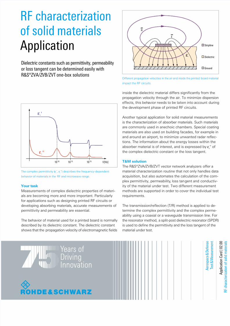
    A    e    r    o    s    p    a    c    e     &     D    e     f    e    n    s    e     T    e    s    t     &     M    e    a    s    u    r    e    m    e    n    t     A    p    p     l     i    c    a    t     i    o    n     C    a    r     d     |     0     2  .     0     0     R     F    c     h    a    r    a    c    t    e    r     i    z    a    t     i    o    n    o     f    s    o     l     i     d    m    a    t    e    r     i    a     l    s Dielectric constants such as permittivity, permeability or loss tangent can be determined easily with R&S®ZVA/Z VB/ZVT one-box solutions RF characterization of solid materials Application  Your task Measurements of complex dielectric properties of materi- als are becoming more and more important. Particularly for applications such as designing printed RF circuits or developing absorbing materials, accurate measurements of permittivity and permeability are essential. The behavior of material used for a printed board is normally described by its dielectric constant. The dielectric constant shows that the propagation velocity of electromagnetic fields Another typical application for solid material measurements is the characterization of absorber materials. Such materials are commonly used in anechoic chambers. Special coating materials are also used on building facades, for example in and around an airport, to minimize unwanted radar reflec- tions. The information about the energy losses within the absorber material is of interest, and is expressed by ε r '' of the complex dielectric constant or the loss tangent. T&M solution The R&S®ZV A/ZVB/ZVT vector network analyzers offer a material characterization routine that not only handles data acquisition, but also automates the calculation of the com- plex permittivity, permeability , loss tan gent and conductiv- ity of the material under test. Two different measurement methods are supported in order to cover the individual test requirements. The transmission/reflection (T/R) method is applied to de- termine the complex permittivity and the complex perme- ability using a coaxial or a waveguide transmission line. For the resonator method, a split-post dielectric resonator (SPDR) is used to define the permittivity and the loss tangent of the material under test. Different propagation velocities in the air and inside the printed board material impact the RF circuits. The complex permittivity ( ε r ', ε r '') describes the frequency-dependent behavior of materials in the RF and microwave range. inside the dielectric material differs significantly from the propagation velocity through the air. To minimize dispersion effects, this behavior needs to be taken into account during the development phase of printed RF circuits. H E ε r Stripline Dielectric Ground f/[Hz] 10 10 10 13 10 15 ε r ' ε r ''
Transcript

8/3/2019 RF Characterization of Solid Materials App En

http://slidepdf.com/reader/full/rf-characterization-of-solid-materials-app-en 1/2

A e r o s p a c e

& D e f e n s e

T e s t & M e a s u r e m e n t

Dielectric constants such as permittivity, permeabilityor loss tangent can be determined easily withR&S®ZVA/ZVB/ZVT one-box solutions

RF characterizationof solid materialsApplication

Your taskMeasurements of complex dielectric properties of materi-als are becoming more and more important. Particularlyfor applications such as designing printed RF circuits ordeveloping absorbing materials, accurate measurements ofpermittivity and permeability are essential.

The behavior of material used for a printed board is normallydescribed by its dielectric constant. The dielectric constantshows that the propagation velocity of electromagnetic fields

Another typical application for solid material measurementsis the characterization of absorber materials. Such materialsare commonly used in anechoic chambers. Special coatingmaterials are also used on building facades, for example inand around an airport, to minimize unwanted radar reflec-tions. The information about the energy losses within theabsorber material is of interest, and is expressed by ε

r'' ofthe complex dielectric constant or the loss tangent.

T&M solutionThe R&S®ZVA/ZVB/ZVT vector network analyzers offer a

material characterization routine that not only handles dataacquisition, but also automates the calculation of the com-plex permittivity, permeability, loss tangent and conductiv-ity of the material under test. Two different measurementmethods are supported in order to cover the individual testrequirements.

The transmission/reflection (T/R) method is applied to de-termine the complex permittivity and the complex perme-ability using a coaxial or a waveguide transmission line. Forthe resonator method, a split-post dielectric resonator (SPDR)is used to define the permittivity and the loss tangent of thematerial under test.

Different propagation velocities in the air and inside the printed board material

impact the RF circuits.

The complex permittivity ( ε r', ε r'') describes the frequency-dependentbehavior of materials in the RF and microwave range.

inside the dielectric material differs significantly from thepropagation velocity through the air. To minimize dispersioneffects, this behavior needs to be taken into account duringthe development phase of printed RF circuits.

H

E

εr

Stripline

Dielectric

Ground

f/[Hz]10 10 10 13 10 15

ε r '

εr ''

8/3/2019 RF Characterization of Solid Materials App En

http://slidepdf.com/reader/full/rf-characterization-of-solid-materials-app-en 2/2

R&S® is a registered trademark of Rohde & Schwarz GmbH & Co. KGTrade names are trademarks of the ownersRF characterization of solid materials | PD 5214.3175.92 | Version 02.00October 2009 | Data without tolerance limits is not binding | Subject to changePrinted in Germany (sv)

Rohde & Schwarz GmbH & Co.KG

Europe, Africa, Middle East +49 89 4129 137 [email protected] America 1 888 TEST RSA (1 888 837 8772)[email protected] America +1 410 910 7988 | [email protected]/Paci c +65 65 13 04 88 | [email protected] www.rohde-schwarz.com

Setups for material measurement tests using the R&S®ZVA/ZVB/ZVT

The clear layout of the user interface of the R&S®ZVA/ZVB/ZVT vector network analyzers facilitates the determination of important material constants ofsolid materials based on the T/R method (top) or the resonator method using an SPDR (bottom).

T/R methodThe T/R method is based on the Nicholson-Ross-Weiralgorithm. The complex permittivity and the complex per-meability are calculated from the S 21- and S 11-parameters,which are obtained by performing transmission and reflec-tion measurements with the R&S®ZVA/ZVB/ZVT.

The material to be tested must be placed either in a coaxialair line or in a section of a waveguide depending on the fre-quency required. Measurements in the range from 300 kHzto 67 GHz are performed with an R&S®ZVA/ZVB/ZVT. Byusing additional R&S®ZVA-Zx converters, the frequencyrange can be extended up to 325 GHz. The measurementresults are graphically displayed in traces as well as record-ed in a table. This data can be read out to an external PC.

The advantage of using a coaxial air line is that measure-ments over a wide frequency range from several kHz up tothe microwave range are possible. The advantage of wave-guides is the simple preparation of the test samples.

Resonator methodThe resonator method is used to measure the permittivityand dielectric loss tangent of laminar dielectrics at a fixedfrequency. Different resonators between 1 GHz and 20 GHzare available. The complex permittivity is calculated on thebasis of the measured resonance of the resonator, with andwithout the sample, and the sample thickness.

The resonator is connected to the R&S®ZVA/ZVB/ZVTthrough the coupling loops. For the measurement, the flatsample is inserted through one of the open sides of theSPDR. The bandpass search function of the network analyzersupports automatic measurement of both the resonancefrequency and the Q-factor – in just one step.

Besides being easy to use, the advantage of the resonatormethod is its high measurement accuracy. The uncertaintypredominantly arises from determining the actual thicknessof the test sample. In addition, the SPDR is suited for verythin and low-loss test samples.

ConclusionThe described test setups from Rohde & Schwarz offer aconvenient and flexible solution that allows you to deter-mine the material constants of your solid materials withhigh precision and in line with your needs.

Schematic of the SPDR.

Metal enclosureDielectric resonator

Coupling loopSample


Recommended