26
RF measurements in CTF3: Phase Calibration and Jitter Alexey Dubrovskiy inputs from Franck Tecker, Luca Timeo and Stephane Ray CLIC/CTF3 experimental verification meeting 08.07.2014
| Date post: | 24-Dec-2015 |
| Category: |
Documents |
| Upload: | bertha-amber-hill |
| View: | 223 times |
| Download: | 0 times |
RF measurements in CTF3:Phase Calibration and Jitter
Alexey Dubrovskiyinputs from Franck Tecker, Luca Timeo and Stephane
Ray
CLIC/CTF3 experimental verification meeting08.07.2014

2
Motivation• Improve the current measurement of RF
phases;• Assess the capability of RF measurement
systems to detect RF jitter.
08.07.2014
Outline• Part 1: Calibration of mixer phase detectors;• Part 2: Measurement of RF Jitter;• Part 3: Correlation between mixer and diode
signals.

3
Part 1: Calibration of mixer phase detectors
08.07.2014
4
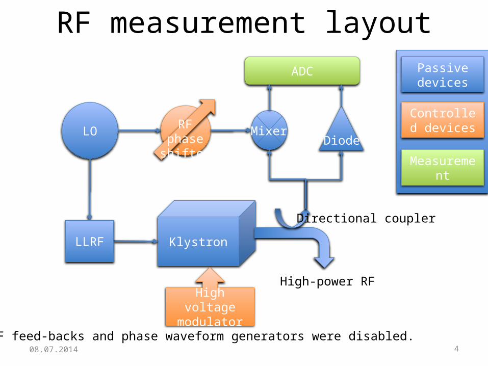
RF measurement layout
Klystron
LO
High-power RF
Directional couplerRF phase
shifter
DiodeMixer
ADC
RF phase shifter
LLRF
High voltage modulator
Passive devices
Controlled devices
Measurement
08.07.2014All RF feed-backs and phase waveform generators were disabled.
5
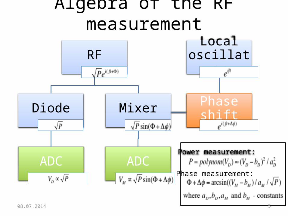
Algebra of the RF measurement
RF
Diode
ADC
Mixer
ADC
Local oscillator
Phase shift
Power measurement:
Phase measurement:
08.07.2014
6
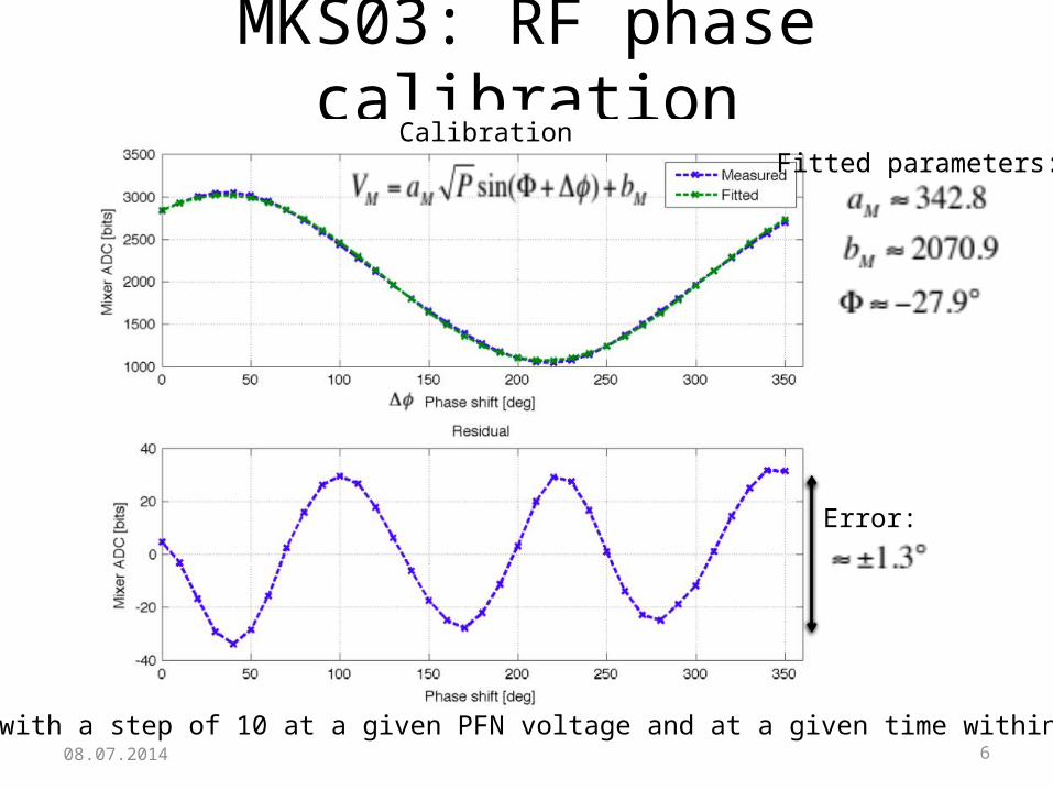
MKS03: RF phase calibrationCalibration
Fitted parameters:
Error:
Phase scan with a step of 10 at a given PFN voltage and at a given time within the pulse08.07.2014

7
MKS03: calibration at different power levels
08.07.2014
RF phases
8
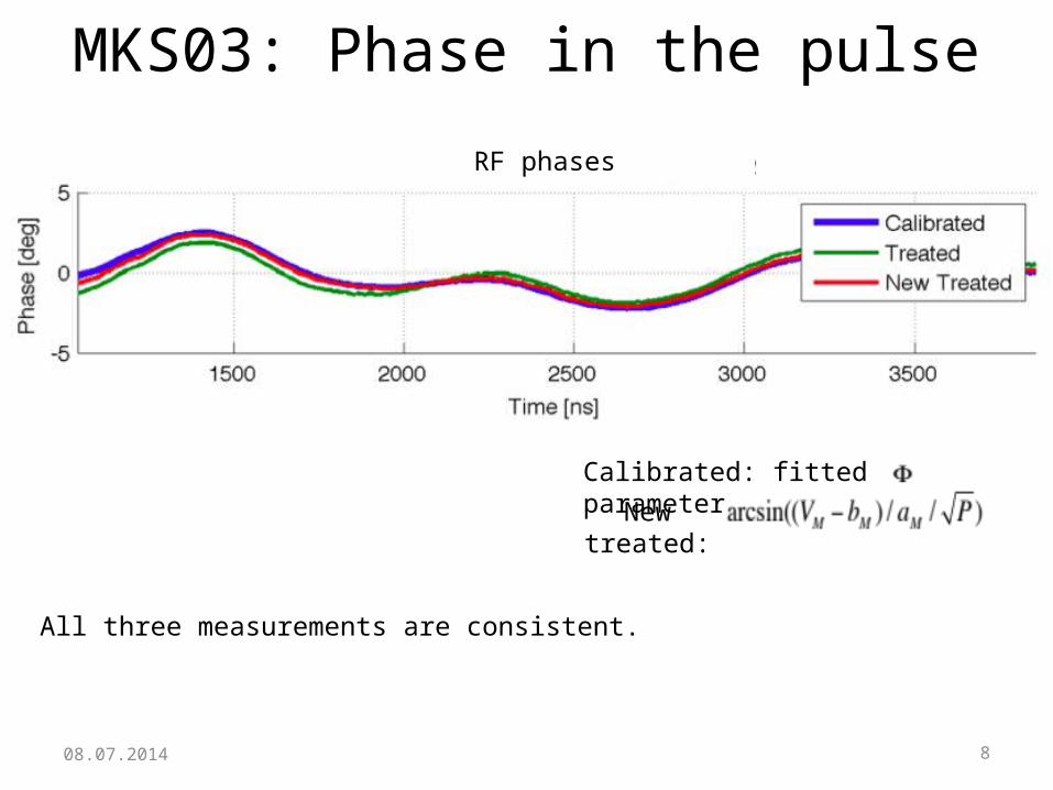
MKS03: Phase in the pulse
08.07.2014
RF phases
New treated:Calibrated: fitted parameter
All three measurements are consistent.
9
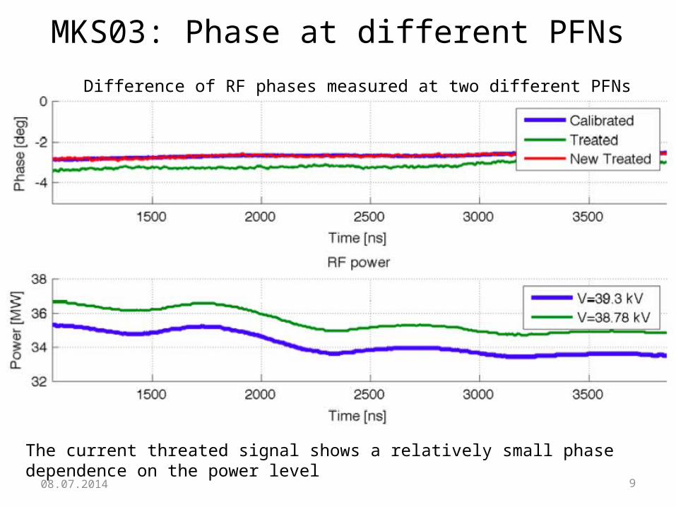
MKS03: Phase at different PFNs
08.07.2014
Difference of RF phases measured at two different PFNs
The current threated signal shows a relatively small phase dependence on the power level

10
Summary of calibration parameters
08.07.2014
Klystron (PKI)
MKS02 162.6 2063.3
MKS03 172.7 2047.6
MKS05 234.5 2110.9
MKS06 211.4 2064.9
MKS07* 269.1 2118.8
RF phase resolution is much smaller for MKS02 and MKS03
(*) Calibration issue on the next slide

11
Calibration issue: MKS07
08.07.2014
RF Power should not change at all when the comp. phase changes!
12
Other issues: MKS02 and MKS05
08.07.2014
The current scaling factors of the treaded phase signals PKI02P and PKI05P are off by a factor of about 2 and 4.
13
Part 2: Measurement of RF Jitter
08.07.2014
14
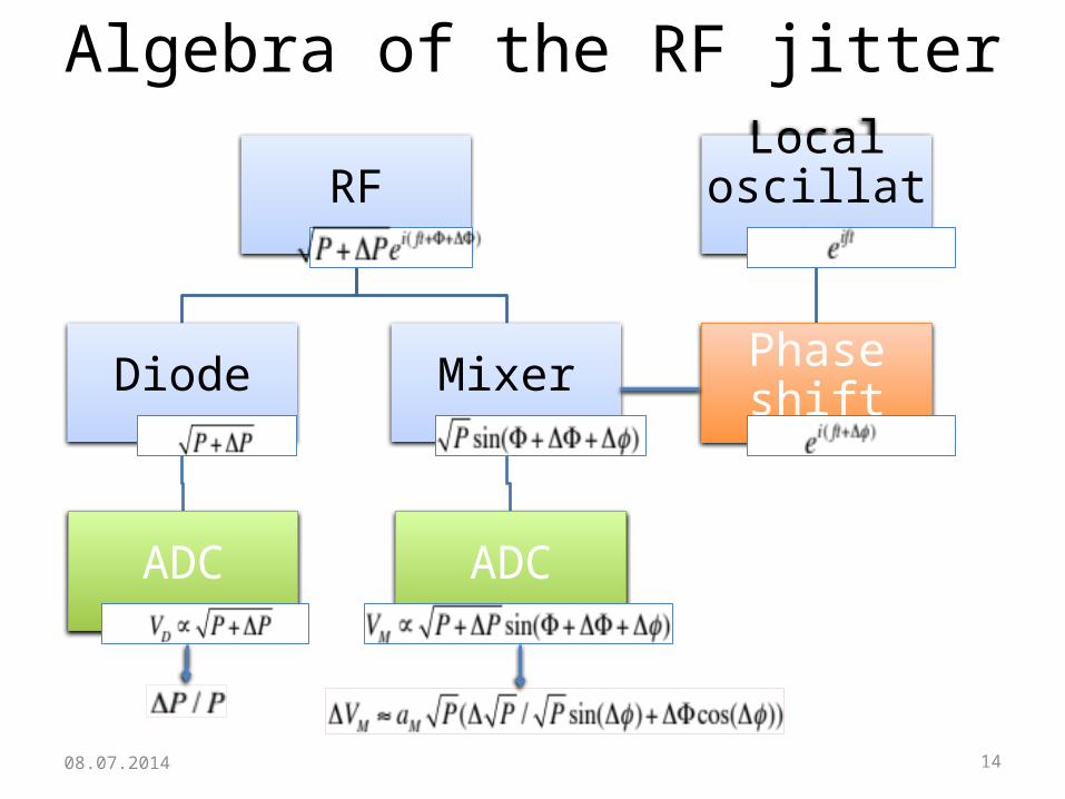
Algebra of the RF jitter
RF
Diode
ADC
Mixer
ADC
Local oscillator
Phase shift
08.07.2014

15
Mixer and diode signals jitters
08.07.2014
Similar power jitters were measured using the mixer and diode signals for MKS03 and MKS05
MKS03
16
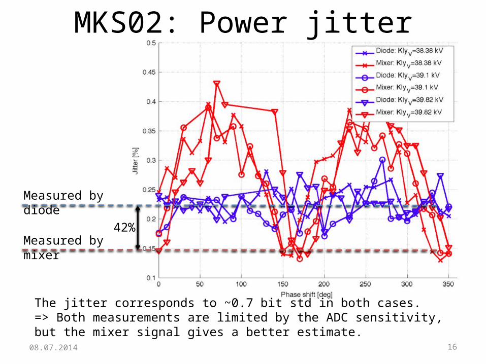
MKS02: Power jitter
08.07.2014
Measured by diode
Measured by mixer42%
The jitter corresponds to ~0.7 bit std in both cases.=> Both measurements are limited by the ADC sensitivity, but the mixer signal gives a better estimate.
17
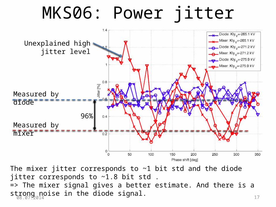
MKS06: Power jitter
08.07.2014
Measured by diode
Measured by mixer96%
The mixer jitter corresponds to ~1 bit std and the diode jitter corresponds to ~1.8 bit std .=> The mixer signal gives a better estimate. And there is a strong noise in the diode signal.
Unexplained high jitter level

18
Part 3: Correlation between mixer and diode signals
08.07.2014

19
Correlation between mixer and diode signals
08.07.2014
Case 1: The RF power deviation linearly depends on the phase deviation, for example, like in the case of a pure high voltage jitter:
Then the correlation is given by: Then the correlation is given by:
Case 2: There is only RF power deviations, which induces jitter on both signals:
Case 3: case 1+ case 2
Then the correlation depends on the phase shift and ratio k1 to k2.
Case 4: case 1+ case 2 + measurement noise
Then the correlation depends on the phase shift, k1, k2 and noise levels.

20
Correlation between mixer and diode signals
08.07.2014
Cases 1, 2 and 3 Case 4 with measurement noise
Case 1(k2=0)
Case 2(k1=0)

21
MKS05: Correlation between mixer and diode signals
08.07.2014
Model parameters:
Modulator voltage jitter
Power jitter
Diode noise
Mixer noise
=> Measured RF jitter is induced by the klystron modulator

22
MKS03: Correlation between mixer and diode signals
08.07.2014
Model parameters:
Modulator voltage jitter
Power jitter
Diode noise
Mixer noise
=> Measured RF jitter is substantially given by the measurement noises

23
MKS06: Correlation between mixer and diode signals
08.07.2014
Model parameters:
Modulator voltage jitter
Power jitter
Diode noise
Mixer noise
=> Measured RF jitter is primary given by the diode measurement noise
24
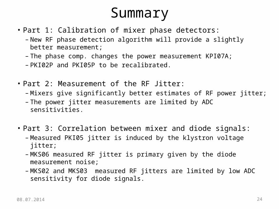
Summary
08.07.2014
• Part 1: Calibration of mixer phase detectors:– New RF phase detection algorithm will provide a slightly better
measurement;– The phase comp. changes the power measurement KPI07A;– PKI02P and PKI05P to be recalibrated.
• Part 2: Measurement of the RF Jitter:– Mixers give significantly better estimates of RF power jitter;– The power jitter measurements are limited by ADC sensitivities.
• Part 3: Correlation between mixer and diode signals:– Measured PKI05 jitter is induced by the klystron voltage jitter;– MKS06 measured RF jitter is primary given by the diode measurement
noise;– MKS02 and MKS03 measured RF jitters are limited by low ADC sensitivity
for diode signals.

2508.07.2014

26
MKS05: Power jitter
08.07.2014


