128
P1026148-002 Rev. A Radio Frequency Identification (RFID) Programming Guide 2 Zebra ® for the ZE500R, R110Xi4, RZ400, RZ600, and RP4T printers/print engines

P1026148-002 Rev. A
Zebra®
Radio Frequency Identification (RFID)
Programming Guide 2
for the ZE500R, R110Xi4, RZ400, RZ600, and RP4T printers/print engines

© 2014 ZIH Corp. The copyrights in this manual and the software and/or firmware in the printer described therein are owned by ZIH Corp. and Zebra’s licensors. Unauthorized reproduction of this manual or the software and/or firmware in the printer may result in imprisonment of up to one year and fines of up to $10,000 (17 U.S.C.506). Copyright violators may be subject to civil liability.
This product may contain ZPL®, ZPL II®, and ZebraLink™ programs; Element Energy Equalizer® Circuit; E3®; and Monotype Imaging fonts. Software © ZIH Corp. All rights reserved worldwide.
ZebraLink and all product names and numbers are trademarks, and Zebra, the Zebra logo, ZPL, ZPL II, Element Energy Equalizer Circuit, and E3 Circuit are registered trademarks of ZIH Corp. All rights reserved worldwide.
All other brand names, product names, or trademarks belong to their respective holders. For additional trademark information, please see “Trademarks” on the product CD.
This RFID product is manufactured under one or more licenses, which contain certain exclusions. This product may not be sold, used, leased, offered for sale, or otherwise transferred, exported, and imported in the Transportation Market. The Transportation Market means (i) Electronic Toll and Traffic Management (ETTM), (ii) Public Sector Vehicle Registration, Inspection and Licensing Programs, (iii) Railroad Locomotive and Wagon tracking, (iv) airport-based ground transportation management systems (GTMS) and taxi dispatch, (v) revenue-based parking, and (vi) vehicle-initiated mobile payment applications, where the RFID tag is initially attached to the vehicle but not incorporated at the point of vehicle manufacture.
Proprietary Statement This manual contains proprietary information of Zebra Technologies Corporation and its subsidiaries (“Zebra Technologies”). It is intended solely for the information and use of parties operating and maintaining the equipment described herein. Such proprietary information may not be used, reproduced, or disclosed to any other parties for any other purpose without the express, written permission of Zebra Technologies Corporation.
Product Improvements Continuous improvement of products is a policy of Zebra Technologies Corporation. All specifications and designs are subject to change without notice.
Liability Disclaimer Zebra Technologies Corporation takes steps to ensure that its published Engineering specifications and manuals are correct; however, errors do occur. Zebra Technologies Corporation reserves the right to correct any such errors and disclaims liability resulting therefrom.
Limitation of Liability In no event shall Zebra Technologies Corporation or anyone else involved in the creation, production, or delivery of the accompanying product (including hardware and software) be liable for any damages whatsoever (including, without limitation, consequential damages including loss of business profits, business interruption, or loss of business information) arising out of the use of, the results of use of, or inability to use such product, even if Zebra Technologies Corporation has been advised of the possibility of such damages. Some jurisdictions do not allow the exclusion or limitation of incidental or consequential damages, so the above limitation or exclusion may not apply to you.
Part Number: P1026148-002

Contents
About This Document . . . . . . . . . . . . . . . . . . . . . . . . . . . . . . . . . . . . . . . . . . . . . . . 7
Who Should Use This Document . . . . . . . . . . . . . . . . . . . . . . . . . . . . . . . . . . . . . . . . . . . . 8
How This Document Is Organized . . . . . . . . . . . . . . . . . . . . . . . . . . . . . . . . . . . . . . . . . . . 8
Contacts . . . . . . . . . . . . . . . . . . . . . . . . . . . . . . . . . . . . . . . . . . . . . . . . . . . . . . . . . . . . . . 10
Document Conventions. . . . . . . . . . . . . . . . . . . . . . . . . . . . . . . . . . . . . . . . . . . . . . . . . . . 12
1 • Introduction to RFID . . . . . . . . . . . . . . . . . . . . . . . . . . . . . . . . . . . . . . . . . . . . 13
RFID Overview . . . . . . . . . . . . . . . . . . . . . . . . . . . . . . . . . . . . . . . . . . . . . . . . . . . . . . . . . 14
Electronic Product Code (EPC) . . . . . . . . . . . . . . . . . . . . . . . . . . . . . . . . . . . . . . . . . 14
EPC Class 1, Generation 2 (Gen 2) . . . . . . . . . . . . . . . . . . . . . . . . . . . . . . . . . . . . . . 15
ZPL Commands for RFID Applications . . . . . . . . . . . . . . . . . . . . . . . . . . . . . . . . . . . . . . . 16
SGD Commands for RFID Applications . . . . . . . . . . . . . . . . . . . . . . . . . . . . . . . . . . . . . . 16
2 • RFID Label Selection and Printer Configuration . . . . . . . . . . . . . . . . . . . . . 17
RFID Label Selection . . . . . . . . . . . . . . . . . . . . . . . . . . . . . . . . . . . . . . . . . . . . . . . . . . . . 18
Considering RFID Transponders . . . . . . . . . . . . . . . . . . . . . . . . . . . . . . . . . . . . . . . . 18
Accounting for Transponder Inlay Position . . . . . . . . . . . . . . . . . . . . . . . . . . . . . . . . . 18
Testing RFID Labels . . . . . . . . . . . . . . . . . . . . . . . . . . . . . . . . . . . . . . . . . . . . . . . . . . 18
Maximizing RFID Potential . . . . . . . . . . . . . . . . . . . . . . . . . . . . . . . . . . . . . . . . . . . . . . . . 20
Avoiding Radio Frequency Interference . . . . . . . . . . . . . . . . . . . . . . . . . . . . . . . . . . . 20
Storing or Handling RFID Labels Correctly. . . . . . . . . . . . . . . . . . . . . . . . . . . . . . . . . 20
Using the Correct Read/Write Power Levels . . . . . . . . . . . . . . . . . . . . . . . . . . . . . . . 20
Using the Correct Programming Position . . . . . . . . . . . . . . . . . . . . . . . . . . . . . . . . . . 21
Firmware Updates. . . . . . . . . . . . . . . . . . . . . . . . . . . . . . . . . . . . . . . . . . . . . . . . . . . . . . . 25
3 • RFID Control Panel Parameters . . . . . . . . . . . . . . . . . . . . . . . . . . . . . . . . . . . 27
4 • Creating Basic RFID Label Formats . . . . . . . . . . . . . . . . . . . . . . . . . . . . . . . . 33
Create and Send an RFID Label Format . . . . . . . . . . . . . . . . . . . . . . . . . . . . . . . . . . . . . 34
3/25/14 RFID Programming Guide 2 P1026148-002 Rev. A
Contents4
Sample RFID Label Formats . . . . . . . . . . . . . . . . . . . . . . . . . . . . . . . . . . . . . . . . . . . . . . 35
RFID Label Format 1—Encode a Gen 2 Tag in Hexadecimal . . . . . . . . . . . . . . . . . . 35
RFID Label Format 2—Encode a Gen 2 Tag in ASCII . . . . . . . . . . . . . . . . . . . . . . . . 36
RFID Label Format 3—Read Data from Tag and Print Data on Label . . . . . . . . . . . . 36
RFID Label Format 4—Encode Tag, Read Tag, and Print Data on Label . . . . . . . . . 37
RFID Label Format 5—Encode Tag, Read Tag, and Return Results to Host . . . . . . . 39
5 • RFID Antenna Location . . . . . . . . . . . . . . . . . . . . . . . . . . . . . . . . . . . . . . . . . . 43
R110Xi4 . . . . . . . . . . . . . . . . . . . . . . . . . . . . . . . . . . . . . . . . . . . . . . . . . . . . . . . . . . . . . . 44
RZ400 and RZ600 . . . . . . . . . . . . . . . . . . . . . . . . . . . . . . . . . . . . . . . . . . . . . . . . . . . . . . 44
RP4T. . . . . . . . . . . . . . . . . . . . . . . . . . . . . . . . . . . . . . . . . . . . . . . . . . . . . . . . . . . . . . . . . 45
6 • Troubleshooting . . . . . . . . . . . . . . . . . . . . . . . . . . . . . . . . . . . . . . . . . . . . . . . . 47
RFID Problems . . . . . . . . . . . . . . . . . . . . . . . . . . . . . . . . . . . . . . . . . . . . . . . . . . . . . . . . . 48
RFID Error Codes and Messages. . . . . . . . . . . . . . . . . . . . . . . . . . . . . . . . . . . . . . . . . . . 51
Error and Status Messages . . . . . . . . . . . . . . . . . . . . . . . . . . . . . . . . . . . . . . . . . . . . 51
Error Codes . . . . . . . . . . . . . . . . . . . . . . . . . . . . . . . . . . . . . . . . . . . . . . . . . . . . . . . . 56
7 • ZPL II Commands for RFID . . . . . . . . . . . . . . . . . . . . . . . . . . . . . . . . . . . . . . . 61
ZPL Overview . . . . . . . . . . . . . . . . . . . . . . . . . . . . . . . . . . . . . . . . . . . . . . . . . . . . . . . . . . 62^HL or ~HL Return RFID Data Log to Host . . . . . . . . . . . . . . . . . . . . . . . . . . . . . . . . . . . 63^HR Calibrate RFID Transponder Position . . . . . . . . . . . . . . . . . . . . . . . . . . . . . . . . . . . 64^HV Host Verification . . . . . . . . . . . . . . . . . . . . . . . . . . . . . . . . . . . . . . . . . . . . . . . . . . . . 70^MM Print Mode . . . . . . . . . . . . . . . . . . . . . . . . . . . . . . . . . . . . . . . . . . . . . . . . . . . . . . . . 71^RB Define EPC Data Structure . . . . . . . . . . . . . . . . . . . . . . . . . . . . . . . . . . . . . . . . . . . . 73^RF Read or Write RFID Format . . . . . . . . . . . . . . . . . . . . . . . . . . . . . . . . . . . . . . . . . . . 75^RI Get RFID Tag ID . . . . . . . . . . . . . . . . . . . . . . . . . . . . . . . . . . . . . . . . . . . . . . . . . . . . 77^RL Lock/Unlock RFID Tag Memory . . . . . . . . . . . . . . . . . . . . . . . . . . . . . . . . . . . . . . . . 79
^RLM – Lock/Unlock the Specified Memory Bank . . . . . . . . . . . . . . . . . . . . . . . . . . . 79
^RLB – Permanently Lock Specified Memory Sections . . . . . . . . . . . . . . . . . . . . . . . 80^RM Enable RFID Motion . . . . . . . . . . . . . . . . . . . . . . . . . . . . . . . . . . . . . . . . . . . . . . . . 82~RO Reset Advanced Counters . . . . . . . . . . . . . . . . . . . . . . . . . . . . . . . . . . . . . . . . . . . 83^RQ Quick Write EPC Data and Passwords . . . . . . . . . . . . . . . . . . . . . . . . . . . . . . . . . . 85^RR Specify RFID Retries for a Block . . . . . . . . . . . . . . . . . . . . . . . . . . . . . . . . . . . . . . . 87^RS Set Up RFID Parameters . . . . . . . . . . . . . . . . . . . . . . . . . . . . . . . . . . . . . . . . . . . . . 89^RU Read Unique RFID Chip Serialization . . . . . . . . . . . . . . . . . . . . . . . . . . . . . . . . . . . 95~RV Report RFID Encoding Results . . . . . . . . . . . . . . . . . . . . . . . . . . . . . . . . . . . . . . . . 98^RW Set RF Power Levels for Read and Write . . . . . . . . . . . . . . . . . . . . . . . . . . . . . . . . 99^RZ Set RFID Tag Password and Lock Tag . . . . . . . . . . . . . . . . . . . . . . . . . . . . . . . . . . 101
8 • SGD Commands for RFID . . . . . . . . . . . . . . . . . . . . . . . . . . . . . . . . . . . . . . . 103
odometer.rfid.valid_resettable . . . . . . . . . . . . . . . . . . . . . . . . . . . . . . . . . . . . . . 105odometer.rfid.void_resettable . . . . . . . . . . . . . . . . . . . . . . . . . . . . . . . . . . . . . . . 106rfid.error.response . . . . . . . . . . . . . . . . . . . . . . . . . . . . . . . . . . . . . . . . . . . . . . . . . 107rfid.position.program . . . . . . . . . . . . . . . . . . . . . . . . . . . . . . . . . . . . . . . . . . . . . . . 108
P1026148-002 Rev. A RFID Programming Guide 2 3/25/14
5Contents
rfid.reader_1.antenna_port . . . . . . . . . . . . . . . . . . . . . . . . . . . . . . . . . . . . . . . . . . 109rfid.reader_1.power.read . . . . . . . . . . . . . . . . . . . . . . . . . . . . . . . . . . . . . . . . . . . . .110rfid.reader_1.power.write . . . . . . . . . . . . . . . . . . . . . . . . . . . . . . . . . . . . . . . . . . . .111rfid.tag.calibrate . . . . . . . . . . . . . . . . . . . . . . . . . . . . . . . . . . . . . . . . . . . . . . . . . . .112rfid.tag.data . . . . . . . . . . . . . . . . . . . . . . . . . . . . . . . . . . . . . . . . . . . . . . . . . . . . . . . .113rfid.tag.test . . . . . . . . . . . . . . . . . . . . . . . . . . . . . . . . . . . . . . . . . . . . . . . . . . . . . . . .114
9 • RFID Applicator Signals . . . . . . . . . . . . . . . . . . . . . . . . . . . . . . . . . . . . . . . . 117
Timing Diagrams for RFID . . . . . . . . . . . . . . . . . . . . . . . . . . . . . . . . . . . . . . . . . . . . . . . .118
Single Signal Mode. . . . . . . . . . . . . . . . . . . . . . . . . . . . . . . . . . . . . . . . . . . . . . . . . . .118
Double Signal Mode . . . . . . . . . . . . . . . . . . . . . . . . . . . . . . . . . . . . . . . . . . . . . . . . . 120
Applicator Interface Connector Pin Configuration. . . . . . . . . . . . . . . . . . . . . . . . . . . . . . 121
Jumper Configurations and Pinouts for +5 V I/O Operation . . . . . . . . . . . . . . . . . . . 124
Pinouts for +24-28 V I/O Operation . . . . . . . . . . . . . . . . . . . . . . . . . . . . . . . . . . . . . 125
Index . . . . . . . . . . . . . . . . . . . . . . . . . . . . . . . . . . . . . . . . . . . . . . . . . . . . . . . . . . . 127
3/25/14 RFID Programming Guide 2 P1026148-002 Rev. A

Contents6
Notes • ____________________________________________________________________
__________________________________________________________________________
__________________________________________________________________________
__________________________________________________________________________
__________________________________________________________________________
__________________________________________________________________________
__________________________________________________________________________
__________________________________________________________________________
__________________________________________________________________________
__________________________________________________________________________
P1026148-002 Rev. A RFID Programming Guide 2 3/25/14

About This Document
This section provides you with contact information, document structure and organization, and additional reference documents.
3/25/14 RFID Programming Guide 2 P1026148-002 Rev. A
ContentsWho Should Use This Document . . . . . . . . . . . . . . . . . . . . . . . . . . . . . . . . . . . . . . . . . . . . 8How This Document Is Organized . . . . . . . . . . . . . . . . . . . . . . . . . . . . . . . . . . . . . . . . . . . 8Contacts . . . . . . . . . . . . . . . . . . . . . . . . . . . . . . . . . . . . . . . . . . . . . . . . . . . . . . . . . . . . . . 10Document Conventions . . . . . . . . . . . . . . . . . . . . . . . . . . . . . . . . . . . . . . . . . . . . . . . . . . 12

About This DocumentWho Should Use This Document
8
Who Should Use This Document
This Programming Guide 2 is intended for use by the label format developer or printer integrator to create label formats that will encode RFID tags. The following printers are supported by this Programming Guide 2:
• ZE500R
• R110Xi4
• RZ400 and RZ600
• RP4T
The RFID features described in this manual require the supported printers to have the firmware version listed in Table 2, RFID Printer Firmware Versions on page 25. For other printers, refer to the original RFID Programming Guide, part number 58978L-XXX, or to RFID Programming Guide 3, part number P1062165-XXX. You can download the most recent version of any of these manuals from http://www.zebra.com/manuals.
How This Document Is Organized
The RFID Programming Guide 2 is set up as follows:
Section Description
About This Document on page 7 This section provides you with contact information, document structure and organization, and additional reference documents.
Introduction to RFID on page 11 This section describes the basic concepts of Radio Frequency Identification (RFID) and how RFID works with your printer.
RFID Label Selection and Printer Configuration on page 17
This section guides you through some tasks that you may need to perform. When you have completed this section, you will be ready to program your RFID label formats.
RFID Control Panel Parameters on page 27
This section shows the control panel parameters that appear on most Zebra RFID printers that have a graphic display.
Creating Basic RFID Label Formats on page 33
After you have selected a transponder type and set your printer appropriately, use the ZPL samples in this section as a base for programming your own RFID label formats.
RFID Antenna Location on page 41 Operations to test the RFID functions and display RFID tag data require you to place an RFID label over the RFID antenna area. This section shows the location of the RFID antenna in the various Zebra RFID printers.
Troubleshooting on page 45 This section provides information about RFID operational errors that you might need to troubleshoot. For other types of problems, consult the User Guide for your printer.
ZPL II Commands for RFID on page 59
This section contains the ZPL II commands for RFID-specific applications.
P1026148-002 Rev. A RFID Programming Guide 2 3/25/14
9About This DocumentHow This Document Is Organized
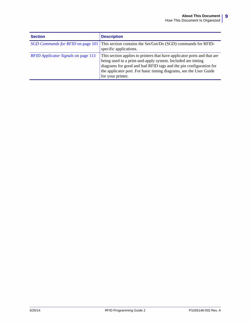
SGD Commands for RFID on page 101 This section contains the Set/Get/Do (SGD) commands for RFID-specific applications.
RFID Applicator Signals on page 113 This section applies to printers that have applicator ports and that are being used in a print-and-apply system. Included are timing diagrams for good and bad RFID tags and the pin configuration for the applicator port. For basic timing diagrams, see the User Guide for your printer.
Section Description
3/25/14 RFID Programming Guide 2 P1026148-002 Rev. A

About This DocumentHow This Document Is Organized
10
Notes • ____________________________________________________________________
__________________________________________________________________________
__________________________________________________________________________
__________________________________________________________________________
__________________________________________________________________________
__________________________________________________________________________
__________________________________________________________________________
__________________________________________________________________________
__________________________________________________________________________
__________________________________________________________________________
P1026148-002 Rev. A RFID Programming Guide 2 3/25/14
1Introduction to RFID
This section describes the basic concepts of Radio Frequency Identification (RFID) and how RFID works with your printer.
3/25/14 RFID Programming Guide 2 P1026148-002 Rev. A
ContentsRFID Overview. . . . . . . . . . . . . . . . . . . . . . . . . . . . . . . . . . . . . . . . . . . . . . . . . . . . . . . . . 12
Electronic Product Code (EPC) . . . . . . . . . . . . . . . . . . . . . . . . . . . . . . . . . . . . . . . . . . 12EPC Class 1, Generation 2 (Gen 2). . . . . . . . . . . . . . . . . . . . . . . . . . . . . . . . . . . . . . . 13
ZPL Commands for RFID Applications . . . . . . . . . . . . . . . . . . . . . . . . . . . . . . . . . . . . . . 14SGD Commands for RFID Applications . . . . . . . . . . . . . . . . . . . . . . . . . . . . . . . . . . . . . . 15
Introduction to RFIDRFID Overview
12
RFID Overview
An RFID printer encodes (writes) information on ultra-thin HF or UHF RFID transponders that are embedded in “smart” labels, tickets, and tags. The printer encodes the information; verifies proper encoding; and prints bar codes, graphics, and/or text on the label’s surface.
The RFID transponder is sometimes called the RFID tag or an inlay. The transponder is usually made of an antenna that is bonded to an integrated circuit (IC) chip. The IC chip contains the RF circuit, coders, decoders, and memory. If you hold an RFID label up to the light, you can see the transponder’s antenna, and you can feel a bump in the label where the IC chip is located.
Encoding and printing of an RFID label usually are completed on the first try, but some failures may occur. If you experience consistent failures, it may signal a problem with the RFID tags, with your label formats, or with the transponder placement.
Electronic Product Code (EPC)
EPC is a product-numbering standard that can be used to identify a variety of items by using RFID technology. The 96-bit EPC code links to an online database, providing a secure way of sharing product-specific information along the supply chain.
EPC Fields
As with bar codes, EPC is divided into numbers that identify the manufacturer and product type. However, EPC contains the following additional information:
• Header—identifies the length, type, structure, version, and generation of EPC
• Manager Number—identifies the company or company entity
• Object Class—similar to a stock keeping unit (SKU)
• Serial Number—the specific instance of the Object Class being tagged
Additional fields may be used as part of the EPC code to encode and decode information from different numbering systems into human-readable form. For more information about EPC specifications, refer to the EPC Global web site.
Note • The information in this section is provided for your convenience only and is subject to change. Go to http://www.epcglobalinc.org for the latest EPC information.
P1026148-002 Rev. A RFID Programming Guide 2 3/25/14

13Introduction to RFIDRFID Overview
EPC Structure in RFID Labels
In the printer, you can subdivide transponder data into unique fields. You can customize these fields to create “smart” labels that meet your needs or that meet the standards necessary in EPC programming.
The ^RB ZPL command is used to define EPC structure. EPC field data can be delimited with any of the following characters:
, ~ ! @ # $ % ^ & * | . < > / \ : ;
See ^RB on page 71 for more information about and examples for defining EPC structure.
EPC Class 1, Generation 2 (Gen 2)
Gen 2 tags typically have a 96-bit EPC identifier and can support large data structures. The size of user memory available (if any) varies by the model and manufacturer of the tag.
Data and Tag Security
Tag Passwords You can set optional 32-bit passwords that allow you to access tag data, to lock tag data, or to permanently disable (kill) a tag. If desired, use the ZPL command ^RZ on page 98 to set the passwords and ^RF on page 73 to read the passwords.
Data Locking Options Tag memory can be safeguarded with flexible locking options using ^RL on page 77 or ^RZ on page 98 (do not alternate between the two commands). For example, you can lock a tag’s blank memory to prevent it from being encoded accidentally and later unlock it for writing. A permanent locking feature prevents rewriting of tag data.
3/25/14 RFID Programming Guide 2 P1026148-002 Rev. A
Introduction to RFIDZPL Commands for RFID Applications
14
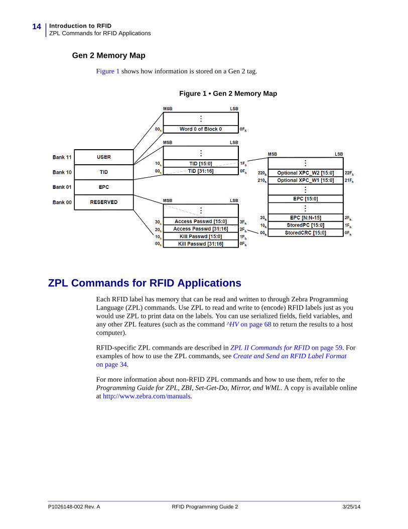
Gen 2 Memory Map
Figure 1 shows how information is stored on a Gen 2 tag.
Figure 1 • Gen 2 Memory Map
ZPL Commands for RFID Applications
Each RFID label has memory that can be read and written to through Zebra Programming Language (ZPL) commands. Use ZPL to read and write to (encode) RFID labels just as you would use ZPL to print data on the labels. You can use serialized fields, field variables, and any other ZPL features (such as the command ^HV on page 68 to return the results to a host computer).
RFID-specific ZPL commands are described in ZPL II Commands for RFID on page 59. For examples of how to use the ZPL commands, see Create and Send an RFID Label Format on page 34.
For more information about non-RFID ZPL commands and how to use them, refer to the Programming Guide for ZPL, ZBI, Set-Get-Do, Mirror, and WML. A copy is available online at http://www.zebra.com/manuals.
P1026148-002 Rev. A RFID Programming Guide 2 3/25/14

15Introduction to RFIDSGD Commands for RFID Applications
SGD Commands for RFID Applications
Your RFID printer is able to use Set/Get/Do (SGD) commands just as it does ZPL commands. Many ZPL commands have equivalent SGD commands. Usually, you will need to run one SGD command for each parameter in the corresponding ZPL command. RFID-specific SGD commands are described in SGD Commands for RFID on page 101.
For more information about non-RFID SGD commands and how to use them, refer to the Programming Guide for ZPL, ZBI, Set-Get-Do, Mirror, and WML. A copy is available online at http://www.zebra.com/manuals.
3/25/14 RFID Programming Guide 2 P1026148-002 Rev. A

Introduction to RFIDSGD Commands for RFID Applications
16
Notes • ____________________________________________________________________
__________________________________________________________________________
__________________________________________________________________________
__________________________________________________________________________
__________________________________________________________________________
__________________________________________________________________________
__________________________________________________________________________
__________________________________________________________________________
__________________________________________________________________________
__________________________________________________________________________
P1026148-002 Rev. A RFID Programming Guide 2 3/25/14
2RFID Label Selection and
Printer Configuration
This section guides you through some tasks that you may need to perform. When you have completed this section, you will be ready to program your RFID label formats.
3/25/14 RFID Programming Guide 2 P1026148-002 Rev. A
ContentsRFID Label Selection . . . . . . . . . . . . . . . . . . . . . . . . . . . . . . . . . . . . . . . . . . . . . . . . . . . . 18
Considering RFID Transponders . . . . . . . . . . . . . . . . . . . . . . . . . . . . . . . . . . . . . . . . . 18Accounting for Transponder Inlay Position . . . . . . . . . . . . . . . . . . . . . . . . . . . . . . . . . 18Testing RFID Labels. . . . . . . . . . . . . . . . . . . . . . . . . . . . . . . . . . . . . . . . . . . . . . . . . . . 18
Maximizing RFID Potential. . . . . . . . . . . . . . . . . . . . . . . . . . . . . . . . . . . . . . . . . . . . . . . . 20Avoiding Radio Frequency Interference. . . . . . . . . . . . . . . . . . . . . . . . . . . . . . . . . . . . 20Storing or Handling RFID Labels Correctly . . . . . . . . . . . . . . . . . . . . . . . . . . . . . . . . . 20Using the Correct Read/Write Power Levels . . . . . . . . . . . . . . . . . . . . . . . . . . . . . . . . 21Using the Correct Programming Position. . . . . . . . . . . . . . . . . . . . . . . . . . . . . . . . . . . 21
Firmware Updates . . . . . . . . . . . . . . . . . . . . . . . . . . . . . . . . . . . . . . . . . . . . . . . . . . . . . . 25
RFID Label Selection and Printer ConfigurationRFID Label Selection
18
RFID Label Selection
To select RFID labels for your printer, consider the RFID transponder and where the transponder is placed in the label. Run tests to determine if the RFID labels that you selected work as you expected before you purchase a large quantity of them.
Considering RFID Transponders
Before you purchase Gen 2 RFID labels, determine which RFID transponder to use. Many RFID transponders look similar, but they behave differently. For different transponders, the following characteristics vary:
• the amount of programmable memory (which corresponds to the amount of data that can be encoded in it)
• the way that data is segmented
• custom commands that can be used (such as block lock)
Select the transponder that best suits your needs.
Accounting for Transponder Inlay Position
Communication between the RFID label and the printer is established when the RFID label’s transponder lines up with the printer’s RFID antenna or active antenna element. The optimal transponder programming position varies with the transponder size, its configuration, and the type of chip used.
Figure 2 on page 19 shows the physical specifications that are taken into account for each transponder when creating placement guidelines. For best results, select a label that meets Zebra RFID Inlay Placement Guidelines. For placement guidelines for Zebra RFID printers, go to http://www.zebra.com/transponders.
Testing RFID Labels
Before you purchase a large quantity of Gen 2 RFID labels, test a small batch to make sure that they function as you need them to. You may need to adjust the transponder location or change transponders if the RFID labels do not work in your application.
To order labels with transponders that are approved for your specific RFID printer, contact your authorized Zebra reseller, or go to http://www.zebra.com/transponders for more information.
Important • Print quality may be affected by printing directly over the transponder. In particular, there is an area on each label immediately around the location of the IC chip where the printer may print with low quality. Design your printed label around the location of the chip in the type of approved RFID label that you select.
P1026148-002 Rev. A RFID Programming Guide 2 3/25/14

19RFID Label Selection and Printer ConfigurationRFID Label Selection
Figure 2 • Transponder Placement Criteria
feed
direc
tion
a Inlay Center
Left inner edge to transponder (inlay) center. Viewed from face stock side, feed direction down.
RF coupling with the transponder can change horizontally across the width of the label. This dimension is relative to the center of the transponder antenna, which is not always the same as the chip location.
This measurement is typically defined with a ±3 mm tolerance.x Inlay
PositionLabel Start to transponder antenna leading edge.
The Inlay Position ensures proper RF encoding with the transponder in the current label. This dimension is relative to the leading edge of the transponder antenna and is the optimal distance from the print line to the antenna during encoding.
This measurement is typically defined with a ±3 mm tolerance.y Inlay
PitchDistance from the leading edge of one transponder antenna to the next.
If transponders are spaced too closely together, coupling to multiple transponders can sometimes occur. This dimension ensures coupling only with the transponder in the current label.
This measurement defines the minimum pitch required to avoid multiple coupling.
3/25/14 RFID Programming Guide 2 P1026148-002 Rev. A
RFID Label Selection and Printer ConfigurationMaximizing RFID Potential
20
Maximizing RFID Potential
After an RFID label is encoded, how well it functions depends where the label is placed on an item, the contents of the item (such as metals or liquids), the location of the RFID readers, and how the label is stored.
Avoiding Radio Frequency Interference
Radio Frequency (RF) interference can be caused by many sources. This interference can affect RFID performance by limiting the range of the RFID tags or preventing reading/writing to the tags.
• Foil and metal-based media should not be used for RFID applications. Metal reflects radio frequency signals and is a leading source of RF interference.
• Water and other liquids can absorb RF signals. Some media adhesives and label materials can be unexpected sources of liquids that cause performance problems.
• Other RF equipment can cause interference if the equipment is positioned too close together. Allow sufficient physical space between the RFID printer and other RF products that share the same bandwidth (such as antennas, readers, wireless LANs, or other RFID printer/encoders).
Perform label placement tests with your readers to identify where labels should be placed on an item to ensure high read rates. Contact the supplier of your RFID transponders for assistance with these types of issues.
Storing or Handling RFID Labels Correctly
Store RFID labels at temperatures ranging from 60 to 203 °F (15.5 to 95 °C) in environmentally stable conditions. Limit RFID label exposure to electrostatic discharge (ESD). Low-humidity environments may require the use of antistatic mats, straps, or clothing to help counter ESD.
P1026148-002 Rev. A RFID Programming Guide 2 3/25/14
21RFID Label Selection and Printer ConfigurationMaximizing RFID Potential
Using the Correct Read/Write Power Levels
Each RFID transponder has specific radio frequency (RF) power setting requirements for read and write operations, which define how much power is necessary to “energize” the transponder in its targeted encoding field. For the recommended power settings for Zebra RFID printers using specific transponders, go to http://www.zebra.com/transponders.
If necessary, you can change your printer’s power settings in three ways:
• through the control panel (see View or Change RFID Read Power on page 30 or View or Change RFID Write Power on page 30)
• with a ZPL command (see ^RW on page 96)
• with SGD commands
• rfid.reader_1.power.read on page 107
• rfid.reader_1.power.write on page 108
Using the Correct Programming Position
If the RFID labels that you are using meet the placement specifications for your printer, you will not need to change the programming position from the default. However, with small label lengths (less than 1 in./25 mm), a program position other than the default may be necessary. See http://www.zebra.com/transponders for more information.
If you do need to change the programming position, you can set a specific position manually or run transponder calibration to allow the printer to select a programming position for you.
Restoring the Printer’s Default Programming Position
By default, the printer will encode RFID labels with the leading edge of the label at the print line. To restore the printer’s default programming position at any time, use one of the following:
• the RESTORE option in the RFID TAG CALIB control panel parameter (see Calibrate RFID Transponder Position on page 29)
• the "RESTORE" option in the rfid.tag.calibrate SGD command (see rfid.tag.calibrate on page 109)
Note • The R110Xi4 printer automatically selects the best antenna element and read/write power levels for the media during RFID transponder calibration.
Note • In printers with firmware versions prior to V53.17.20Z, any time that a new label length is measured, the programming position returns to the default value. This can happen in any of the following situations:
• any calibration methods that measure length• ^SS parameter for Label Pitch Length• failed RFID tag calibrationWith firmware version V53.17.20Z and later, the program position is persistent.
3/25/14 RFID Programming Guide 2 P1026148-002 Rev. A

RFID Label Selection and Printer ConfigurationMaximizing RFID Potential
22
Setting the Programming Position Manually
You can manually set a programming position in two ways:
• using the ^RS ZPL command (see ^RS on page 87)
• using the rfid.position.program SGD command (see rfid.position.program on page 105)
Where the program position is displayed (control panel, configuration label, or web page), the program position shows the value based on the method in which it was set:
• xxxx dots (absolute mode)
• Fxxx millimeters (relative mode)
• Byy millimeters (relative mode)
Absolute Mode (dots from top of label method) Absolute mode sets the read/write position of the transponder in vertical (Y axis) dot rows from the top of the label. Set to 0 (no movement) if the transponder is already in the effective area without moving the media.
Relative Mode (leading edge method) Relative mode sets the read/write position relative to the leading edge of the label. Specified in millimeters and allowing for distances before and after the label’s leading edge. Values are represented in millimeters relative to the leading edge of the label.
Setting the Programming Position Using Transponder Calibration
You can perform two types of calibration on an RFID printer. Media calibration sets the printer for the media criteria, such as label length and interlabel gap. RFID transponder calibration sets the printers for RFID criteria, such as the optimal programming position. Before running transponder calibration, make sure that your printer is calibrated for the media being used and that the printhead is closed. For more information on media calibration, refer to the User Guide for your printer.
Transponder calibration can be performed in several ways:
• using the RFID TAG CALIB control panel parameter (see Calibrate RFID Transponder Position on page 29)
• using the ^HR ZPL command (see ^HR on page 62). This command also returns a results table to the host computer.
• using the "RUN" option in the rfid.tag.calibrate SGD command (see rfid.tag.calibrate on page 109).
Table 1 shows the results of transponder calibration on the RFID printers supported by this manual.
P1026148-002 Rev. A RFID Programming Guide 2 3/25/14
23RFID Label Selection and Printer ConfigurationMaximizing RFID Potential
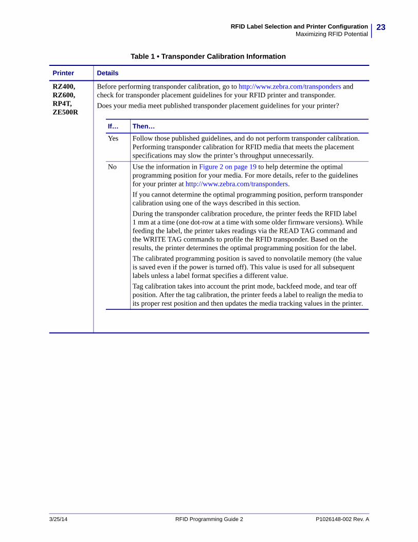
Table 1 • Transponder Calibration Information
Printer Details
RZ400, RZ600, RP4T, ZE500R
Before performing transponder calibration, go to http://www.zebra.com/transponders and check for transponder placement guidelines for your RFID printer and transponder.
Does your media meet published transponder placement guidelines for your printer?
If… Then…
Yes Follow those published guidelines, and do not perform transponder calibration. Performing transponder calibration for RFID media that meets the placement specifications may slow the printer’s throughput unnecessarily.
No Use the information in Figure 2 on page 19 to help determine the optimal programming position for your media. For more details, refer to the guidelines for your printer at http://www.zebra.com/transponders.
If you cannot determine the optimal programming position, perform transponder calibration using one of the ways described in this section.
During the transponder calibration procedure, the printer feeds the RFID label 1 mm at a time (one dot-row at a time with some older firmware versions). While feeding the label, the printer takes readings via the READ TAG command and the WRITE TAG commands to profile the RFID transponder. Based on the results, the printer determines the optimal programming position for the label.
The calibrated programming position is saved to nonvolatile memory (the value is saved even if the power is turned off). This value is used for all subsequent labels unless a label format specifies a different value.
Tag calibration takes into account the print mode, backfeed mode, and tear off position. After the tag calibration, the printer feeds a label to realign the media to its proper rest position and then updates the media tracking values in the printer.
3/25/14 RFID Programming Guide 2 P1026148-002 Rev. A
RFID Label Selection and Printer ConfigurationMaximizing RFID Potential
24
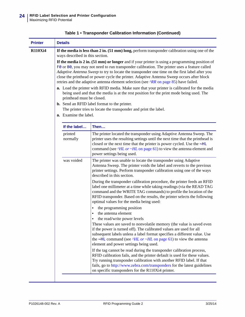
R110Xi4 If the media is less than 2 in. (51 mm) long, perform transponder calibration using one of the ways described in this section.
If the media is 2 in. (51 mm) or longer and if your printer is using a programming position of F0 or B0, you may not need to run transponder calibration. The printer uses a feature called Adaptive Antenna Sweep to try to locate the transponder one time on the first label after you close the printhead or power cycle the printer. Adaptive Antenna Sweep occurs after block retries and the adaptive antenna element selection (see ^RR on page 85) have failed.
a. Load the printer with RFID media. Make sure that your printer is calibrated for the media being used and that the media is at the rest position for the print mode being used. The printhead must be closed.
b. Send an RFID label format to the printer.The printer tries to locate the transponder and print the label.
a. Examine the label.
Table 1 • Transponder Calibration Information (Continued)
Printer Details
If the label… Then…
printed normally
The printer located the transponder using Adaptive Antenna Sweep. The printer uses the resulting settings until the next time that the printhead is closed or the next time that the printer is power cycled. Use the ~HL command (see ̂ HL or ~HL on page 61) to view the antenna element and power settings being used.
was voided The printer was unable to locate the transponder using Adaptive Antenna Sweep. The printer voids the label and reverts to the previous printer settings. Perform transponder calibration using one of the ways described in this section.
During the transponder calibration procedure, the printer feeds an RFID label one millimeter at a time while taking readings (via the READ TAG command and the WRITE TAG commands) to profile the location of the RFID transponder. Based on the results, the printer selects the following optimal values for the media being used:
• the programming position• the antenna element• the read/write power levelsThese values are saved to nonvolatile memory (the value is saved even if the power is turned off). The calibrated values are used for all subsequent labels unless a label format specifies a different value. Use the ~HL command (see ^HL or ~HL on page 61) to view the antenna element and power settings being used.
If the tag cannot be read during the transponder calibration process, RFID calibration fails, and the printer default is used for these values. Try running transponder calibration with another RFID label. If that fails, go to http://www.zebra.com/transponders for the latest guidelines on specific transponders for the R110Xi4 printer.
P1026148-002 Rev. A RFID Programming Guide 2 3/25/14

25RFID Label Selection and Printer ConfigurationFirmware Updates
Firmware Updates
Zebra may update printer and reader firmware periodically to add new functionality or to fix any known issues with older firmware. At any time, you may download the most recent firmware for your RFID printer. For the firmware files and the downloading instructions, go to http://www.zebra.com/firmware.
The RFID printers supported by this manual must have the firmware version listed in Table 2. For other printers, refer to the original RFID Programming Guide, part number 58978L-XXX, or to RFID Programming Guide 3, part number P1062165-XXX. You can download the most recent version of any of these manuals from http://www.zebra.com/manuals.
Important • Download only the firmware designed for your printer and for your region or country. Downloading inappropriate firmware may disable your printer or some or all of the RFID functionality.
Before downloading new firmware, print a printer configuration label and verify that the new printer firmware version is appropriate for your printer. The underlined part of the firmware version shown in Table 2 must match exactly with what was originally installed on your printer.
Table 2 • RFID Printer Firmware Versions
Printer Firmware Version
R110Xi4 V53.17.7 or later*
RZ400/RZ600 R53.X.X or V53.17.7*
ZE500R V53.17.20 or later
RP4T SHSTR11t22
* Requires V53.17.20 or later for the latest features.
3/25/14 RFID Programming Guide 2 P1026148-002 Rev. A

RFID Label Selection and Printer ConfigurationFirmware Updates
26
Notes • ____________________________________________________________________
__________________________________________________________________________
__________________________________________________________________________
__________________________________________________________________________
__________________________________________________________________________
__________________________________________________________________________
__________________________________________________________________________
__________________________________________________________________________
__________________________________________________________________________
__________________________________________________________________________
P1026148-002 Rev. A RFID Programming Guide 2 3/25/14
3RFID Control Panel
Parameters
This section shows the control panel parameters that appear on most Zebra RFID printers that have a graphic display.
The parameters shown in Table 3 on page 28 display only if you have an RFID reader and antenna installed. Depending on which type of printer you have and which version of firmware that you are using, not all parameters or options for the parameters may display.
Note • The RP4T can display these parameters with the appropriate menu setup. Refer to the User Guide for your printer for more information.
Note • When you enter Setup mode, press PREVIOUS or MINUS (-) (depending on the printer) to access the RFID parameters without scrolling through all of the other printer parameters. Refer to the User Guide for your printer for specific instructions on how to use the control panel.
3/25/14 RFID Programming Guide 2 P1026148-002 Rev. A
RFID Control Panel Parameters28
Table 3 • RFID Parameters (Page 1 of 5)
Parameter Action/Explanation
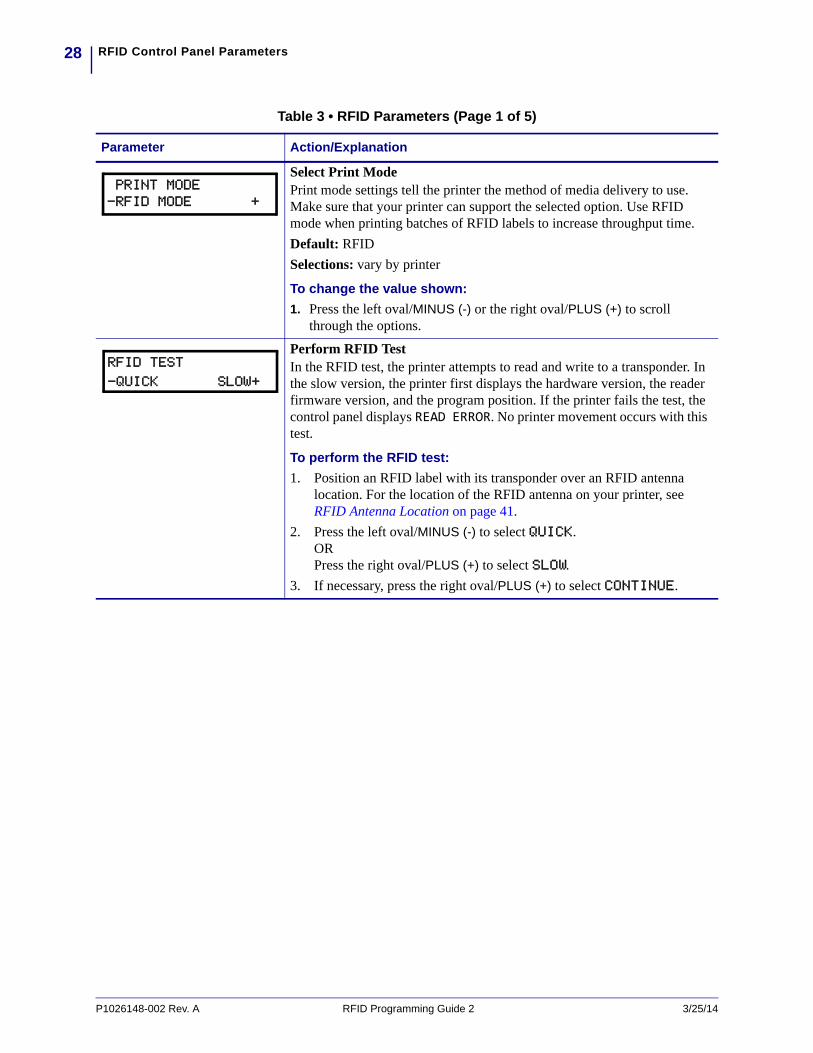
Select Print ModePrint mode settings tell the printer the method of media delivery to use. Make sure that your printer can support the selected option. Use RFID mode when printing batches of RFID labels to increase throughput time.
Default: RFID
Selections: vary by printer
To change the value shown:
1. Press the left oval/MINUS (-) or the right oval/PLUS (+) to scroll through the options.
Perform RFID TestIn the RFID test, the printer attempts to read and write to a transponder. In the slow version, the printer first displays the hardware version, the reader firmware version, and the program position. If the printer fails the test, the control panel displays READ ERROR. No printer movement occurs with this test.
To perform the RFID test:
1. Position an RFID label with its transponder over an RFID antenna location. For the location of the RFID antenna on your printer, see RFID Antenna Location on page 41.
2. Press the left oval/MINUS (-) to select QUICK.ORPress the right oval/PLUS (+) to select SLOW.
3. If necessary, press the right oval/PLUS (+) to select CONTINUE.
PRINT MODE-RFID MODE +
RFID TEST
-QUICK SLOW+
P1026148-002 Rev. A RFID Programming Guide 2 3/25/14

29RFID Control Panel Parameters
Calibrate RFID Transponder PositionThis parameter runs a transponder calibration, which sets the programming position and selects the appropriate antenna in some printers, or it restores the programming position back to the printer default.
RESTORE Selecting this option resets the RFID programming position to the printer default. No label movement occurs.
To restore the programming position to the default:
1. Press the left oval/MINUS (-) to select RESTORE.
RUN Selecting this option begins the transpoonder calibration procedure. The printer moves the media, calibrates the RFID transponder position, and determines the optimal programming position for the RFID media being used. This is the same as running the command ^HR on page 62, but this option does not return the transponder calibration results to the host computer. For the R110Xi4 printer, this option also selects the best antenna element and read/write power levels for the media.
Important • Before using this option, see Using the Correct Programming Position on page 21. Running this parameter may not be the best option for your printer.
To calibrate an RFID tag:
1. Load the printer with RFID media. Make sure that your printer is calibrated for the media being used.
2. For the R110Xi4 printer, remove all transponders from the first 1.25 in. (32 mm) of media. Allow this portion of the media to extend out the front of the printer to allow for backfeed during the transponder calibration procedure.
3. Close the printhead.4. Press the right oval/PLUS (+) to select RUN.
View Valid RFID Label CounterThis parameter displays the total number of valid RFID labels that have been printed/encoded. You can use this parameter or odometer.rfid.valid_resettable on page 102 to reset the counter to zero.
To reset the counter to zero:
1. Press the right oval/PLUS (+) to select RESET.
View Void RFID Label CounterThis parameter displays the total number of RFID labels that have been voided. You can use this parameter or odometer.rfid.void_resettable on page 103 to reset the counter to zero.
To reset the counter to zero:
1. Press the right oval/PLUS (+) to select RESET.
Table 3 • RFID Parameters (Page 2 of 5)
Parameter Action/Explanation
RFID TAG CALIB-RESTORE RUN+
RFID VALID CTR
956 <RESET>+
RFID VOID CTR
23 <RESET>+
3/25/14 RFID Programming Guide 2 P1026148-002 Rev. A
RFID Control Panel Parameters30
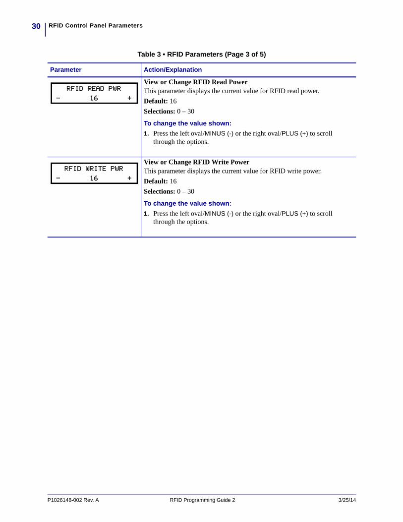
View or Change RFID Read PowerThis parameter displays the current value for RFID read power.
Default: 16
Selections: 0 – 30
To change the value shown:
1. Press the left oval/MINUS (-) or the right oval/PLUS (+) to scroll through the options.
View or Change RFID Write PowerThis parameter displays the current value for RFID write power.
Default: 16
Selections: 0 – 30
To change the value shown:
1. Press the left oval/MINUS (-) or the right oval/PLUS (+) to scroll through the options.
Table 3 • RFID Parameters (Page 3 of 5)
Parameter Action/Explanation
RFID READ PWR
- 16 +
RFID WRITE PWR
- 16 +
P1026148-002 Rev. A RFID Programming Guide 2 3/25/14
31RFID Control Panel Parameters
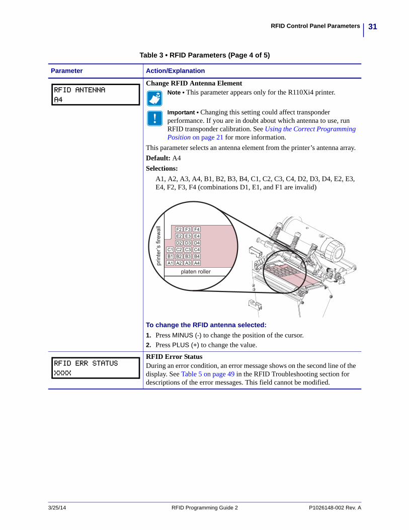
Change RFID Antenna ElementNote • This parameter appears only for the R110Xi4 printer.
Important • Changing this setting could affect transponder performance. If you are in doubt about which antenna to use, run RFID transponder calibration. See Using the Correct Programming Position on page 21 for more information.
This parameter selects an antenna element from the printer’s antenna array.
Default: A4
Selections:
A1, A2, A3, A4, B1, B2, B3, B4, C1, C2, C3, C4, D2, D3, D4, E2, E3, E4, F2, F3, F4 (combinations D1, E1, and F1 are invalid)
To change the RFID antenna selected:
1. Press MINUS (-) to change the position of the cursor.2. Press PLUS (+) to change the value.
RFID Error StatusDuring an error condition, an error message shows on the second line of the display. See Table 5 on page 49 in the RFID Troubleshooting section for descriptions of the error messages. This field cannot be modified.
Table 3 • RFID Parameters (Page 4 of 5)
Parameter Action/Explanation
RFID ANTENNA
A4
RFID ERR STATUS
XXXX
3/25/14 RFID Programming Guide 2 P1026148-002 Rev. A
RFID Control Panel Parameters32
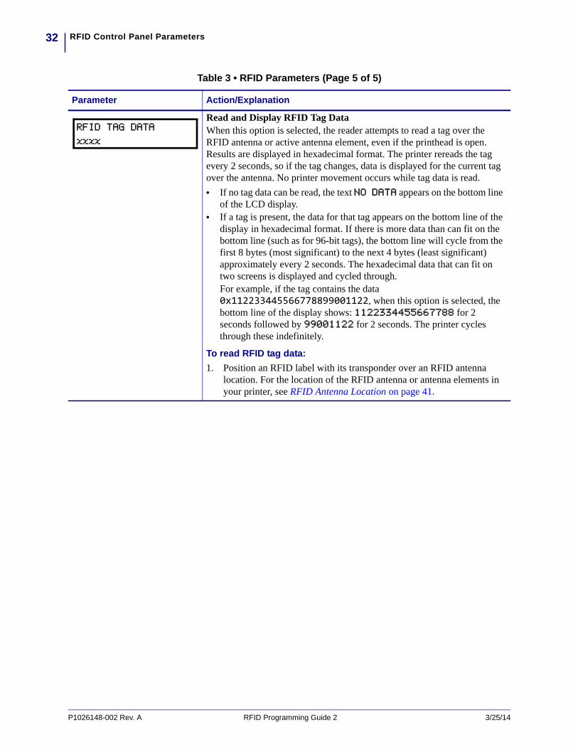
Read and Display RFID Tag DataWhen this option is selected, the reader attempts to read a tag over the RFID antenna or active antenna element, even if the printhead is open. Results are displayed in hexadecimal format. The printer rereads the tag every 2 seconds, so if the tag changes, data is displayed for the current tag over the antenna. No printer movement occurs while tag data is read.
• If no tag data can be read, the text NO DATA appears on the bottom line of the LCD display.
• If a tag is present, the data for that tag appears on the bottom line of the display in hexadecimal format. If there is more data than can fit on the bottom line (such as for 96-bit tags), the bottom line will cycle from the first 8 bytes (most significant) to the next 4 bytes (least significant) approximately every 2 seconds. The hexadecimal data that can fit on two screens is displayed and cycled through.For example, if the tag contains the data 0x112233445566778899001122, when this option is selected, the bottom line of the display shows: 1122334455667788 for 2 seconds followed by 99001122 for 2 seconds. The printer cycles through these indefinitely.
To read RFID tag data:
1. Position an RFID label with its transponder over an RFID antenna location. For the location of the RFID antenna or antenna elements in your printer, see RFID Antenna Location on page 41.
Table 3 • RFID Parameters (Page 5 of 5)
Parameter Action/Explanation
RFID TAG DATA
xxxx
P1026148-002 Rev. A RFID Programming Guide 2 3/25/14

4Creating Basic RFID
Label Formats
After you have selected a transponder type and set your printer appropriately, use the ZPL samples in this section as a base for programming your own RFID label formats.
For specific information about individual ZPL commands, see ZPL II Commands for RFID on page 59.
3/25/14 RFID Programming Guide 2 P1026148-002 Rev. A
ContentsCreate and Send an RFID Label Format . . . . . . . . . . . . . . . . . . . . . . . . . . . . . . . . . . . . . 34Sample RFID Label Formats . . . . . . . . . . . . . . . . . . . . . . . . . . . . . . . . . . . . . . . . . . . . . . 35
RFID Label Format 1—Encode a Gen 2 Tag in Hexadecimal . . . . . . . . . . . . . . . . . . . 35RFID Label Format 2—Encode a Gen 2 Tag in ASCII. . . . . . . . . . . . . . . . . . . . . . . . . 36RFID Label Format 3—Read Data from Tag and Print Data on Label . . . . . . . . . . . . . 36RFID Label Format 4—Encode Tag, Read Tag, and Print Data on Label . . . . . . . . . . 37RFID Label Format 5—Encode Tag, Read Tag, and Return Results to Host . . . . . . . 39
Creating Basic RFID Label FormatsCreate and Send an RFID Label Format
34
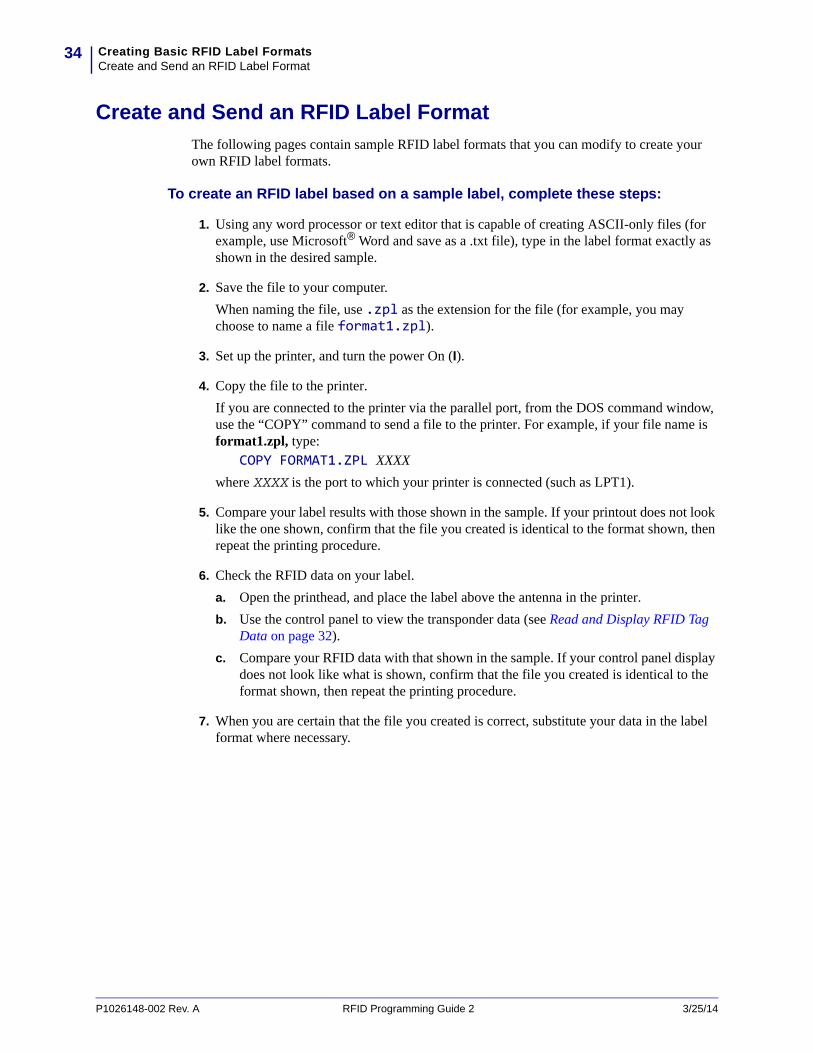
Create and Send an RFID Label Format
The following pages contain sample RFID label formats that you can modify to create your own RFID label formats.
To create an RFID label based on a sample label, complete these steps:
1. Using any word processor or text editor that is capable of creating ASCII-only files (for example, use Microsoft® Word and save as a .txt file), type in the label format exactly as shown in the desired sample.
2. Save the file to your computer.
When naming the file, use .zpl as the extension for the file (for example, you may choose to name a file format1.zpl).
3. Set up the printer, and turn the power On (I).
4. Copy the file to the printer.
If you are connected to the printer via the parallel port, from the DOS command window, use the “COPY” command to send a file to the printer. For example, if your file name is format1.zpl, type:
COPY FORMAT1.ZPL XXXX
where XXXX is the port to which your printer is connected (such as LPT1).
5. Compare your label results with those shown in the sample. If your printout does not look like the one shown, confirm that the file you created is identical to the format shown, then repeat the printing procedure.
6. Check the RFID data on your label.
a. Open the printhead, and place the label above the antenna in the printer.
b. Use the control panel to view the transponder data (see Read and Display RFID Tag Data on page 32).
c. Compare your RFID data with that shown in the sample. If your control panel display does not look like what is shown, confirm that the file you created is identical to the format shown, then repeat the printing procedure.
7. When you are certain that the file you created is correct, substitute your data in the label format where necessary.
P1026148-002 Rev. A RFID Programming Guide 2 3/25/14
35Creating Basic RFID Label FormatsSample RFID Label Formats
Sample RFID Label Formats
Use the formats in this section to assist you in creating your own RFID label formats.
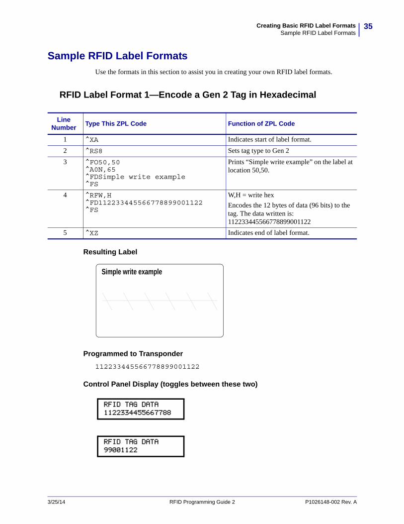
RFID Label Format 1—Encode a Gen 2 Tag in Hexadecimal
Resulting Label
Programmed to Transponder
112233445566778899001122
Control Panel Display (toggles between these two)
Line Number
Type This ZPL Code Function of ZPL Code
1 ^XA Indicates start of label format.
2 ^RS8 Sets tag type to Gen 2
3 ^FO50,50^A0N,65^FDSimple write example^FS
Prints “Simple write example” on the label at location 50,50.
4 ^RFW,H^FD112233445566778899001122^FS
W,H = write hex
Encodes the 12 bytes of data (96 bits) to the tag. The data written is: 112233445566778899001122
5 ^XZ Indicates end of label format.
Simple write example
RFID TAG DATA 1122334455667788
RFID TAG DATA 99001122
3/25/14 RFID Programming Guide 2 P1026148-002 Rev. A
Creating Basic RFID Label FormatsSample RFID Label Formats
36
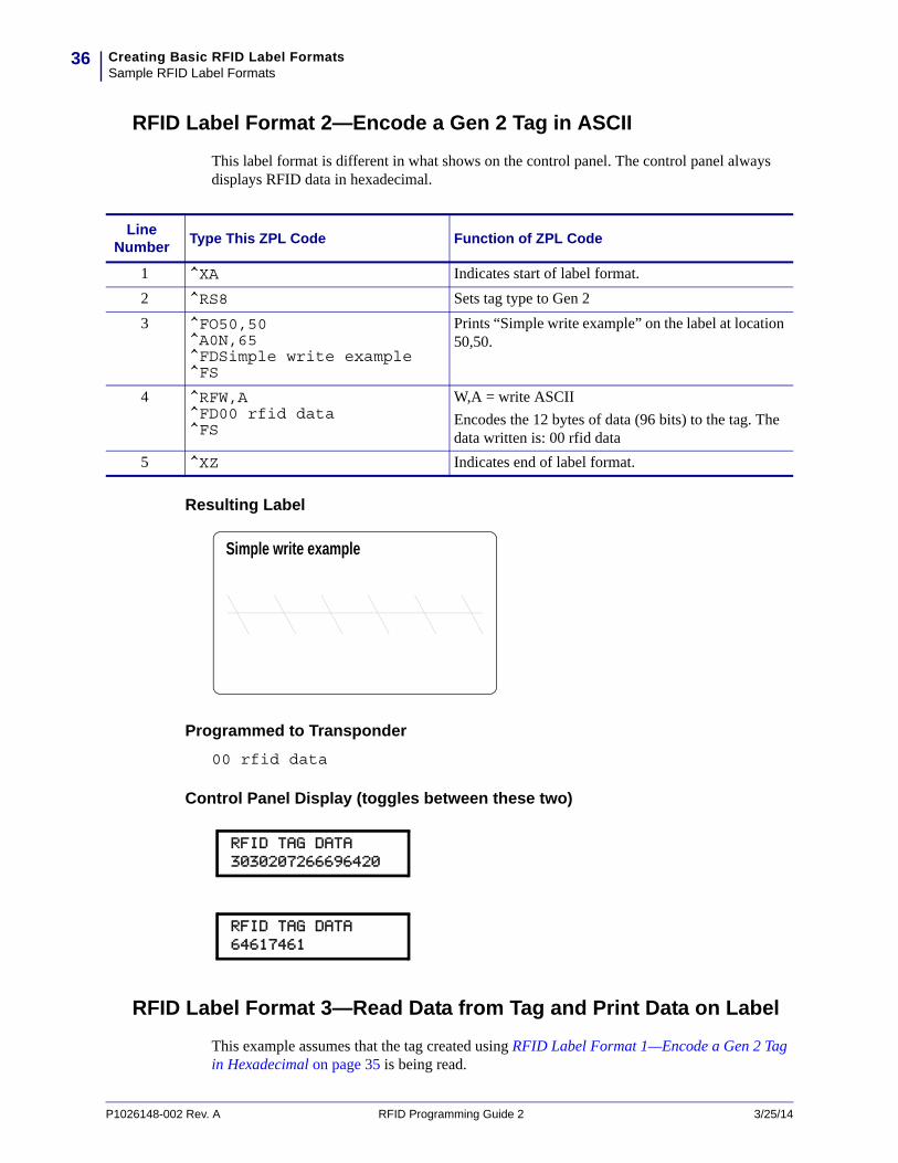
RFID Label Format 2—Encode a Gen 2 Tag in ASCII
This label format is different in what shows on the control panel. The control panel always displays RFID data in hexadecimal.
Resulting Label
Programmed to Transponder
00 rfid data
Control Panel Display (toggles between these two)
RFID Label Format 3—Read Data from Tag and Print Data on Label
This example assumes that the tag created using RFID Label Format 1—Encode a Gen 2 Tag in Hexadecimal on page 35 is being read.
Line Number
Type This ZPL Code Function of ZPL Code
1 ^XA Indicates start of label format.
2 ^RS8 Sets tag type to Gen 2
3 ^FO50,50^A0N,65^FDSimple write example^FS
Prints “Simple write example” on the label at location 50,50.
4 ^RFW,A^FD00 rfid data^FS
W,A = write ASCII
Encodes the 12 bytes of data (96 bits) to the tag. The data written is: 00 rfid data
5 ^XZ Indicates end of label format.
Simple write example
RFID TAG DATA 3030207266696420
RFID TAG DATA 64617461
P1026148-002 Rev. A RFID Programming Guide 2 3/25/14
37Creating Basic RFID Label FormatsSample RFID Label Formats
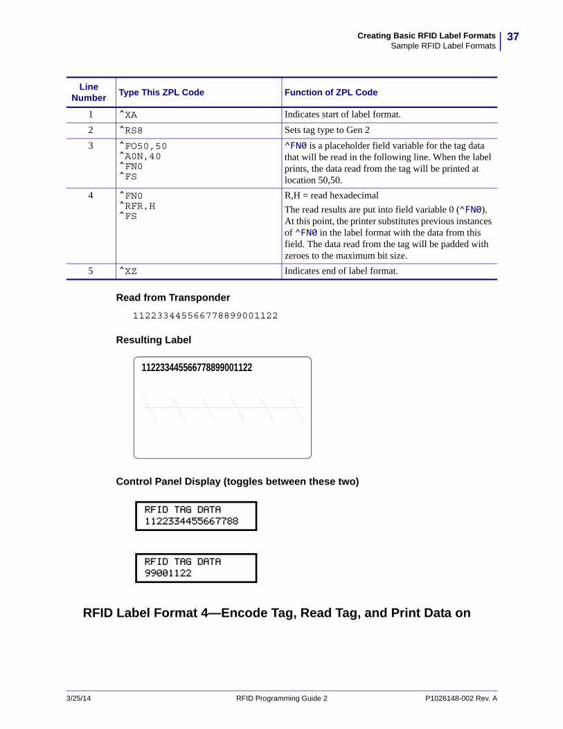
Read from Transponder
112233445566778899001122
Resulting Label
Control Panel Display (toggles between these two)
RFID Label Format 4—Encode Tag, Read Tag, and Print Data on
Line Number
Type This ZPL Code Function of ZPL Code
1 ^XA Indicates start of label format.
2 ^RS8 Sets tag type to Gen 2
3 ^FO50,50^A0N,40^FN0^FS
^FN0 is a placeholder field variable for the tag data that will be read in the following line. When the label prints, the data read from the tag will be printed at location 50,50.
4 ^FN0^RFR,H^FS
R,H = read hexadecimal
The read results are put into field variable 0 (^FN0). At this point, the printer substitutes previous instances of ^FN0 in the label format with the data from this field. The data read from the tag will be padded with zeroes to the maximum bit size.
5 ^XZ Indicates end of label format.
112233445566778899001122
RFID TAG DATA 1122334455667788
RFID TAG DATA 99001122
3/25/14 RFID Programming Guide 2 P1026148-002 Rev. A

Creating Basic RFID Label FormatsSample RFID Label Formats
38
Label
Programmed to Transponder
306461746100000000000000
Read from Transponder
306461746100000000000000
Resulting Label
Line Number
Type This ZPL Code Function of ZPL Code
1 ^XA Indicates start of label format.
2 ^RS8 Sets tag type to Gen 2
3 ^FO60,60^A0N,40^FN7^FS
When the label prints, the data read from the tag at field variable 7 (^FN7) will be printed at location 60,60.
4 ^RFW,A^FD0data^FS
W,A = write ASCII
Encodes “0data” into the block padded with 8 bytes of zeroes to make the data 12 bytes. The data written is: 306461746100000000000000 (“0data” in ASCII)
5 ^FN7^RFR,A^FS
R,A = read ASCII
Reads the tag data into field variable 7 (^FN7). After this occurs, any fields in this label format that have ^FN7 will be replaced with this read data.
6 ^XZ Indicates end of label format.
0data
P1026148-002 Rev. A RFID Programming Guide 2 3/25/14
39Creating Basic RFID Label FormatsSample RFID Label Formats
Control Panel Display (toggles between these two)
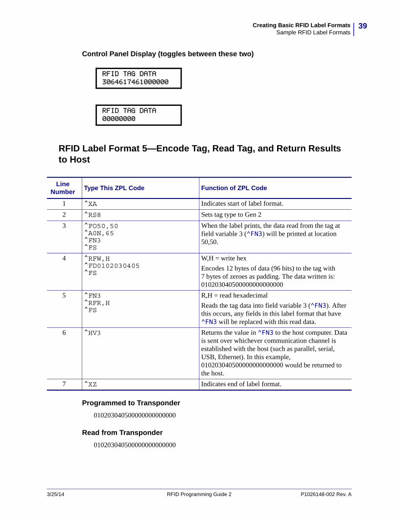
RFID Label Format 5—Encode Tag, Read Tag, and Return Results to Host
Programmed to Transponder
010203040500000000000000
Read from Transponder
010203040500000000000000
RFID TAG DATA 3064617461000000
RFID TAG DATA 00000000
Line Number
Type This ZPL Code Function of ZPL Code
1 ^XA Indicates start of label format.
2 ^RS8 Sets tag type to Gen 2
3 ^FO50,50^A0N,65^FN3^FS
When the label prints, the data read from the tag at field variable 3 (^FN3) will be printed at location 50,50.
4 ^RFW,H^FD0102030405^FS
W,H = write hex
Encodes 12 bytes of data (96 bits) to the tag with 7 bytes of zeroes as padding. The data written is: 010203040500000000000000
5 ^FN3^RFR,H^FS
R,H = read hexadecimal
Reads the tag data into field variable 3 (^FN3). After this occurs, any fields in this label format that have ^FN3 will be replaced with this read data.
6 ^HV3 Returns the value in ^FN3 to the host computer. Data is sent over whichever communication channel is established with the host (such as parallel, serial, USB, Ethernet). In this example, 010203040500000000000000 would be returned to the host.
7 ^XZ Indicates end of label format.
3/25/14 RFID Programming Guide 2 P1026148-002 Rev. A

Creating Basic RFID Label FormatsSample RFID Label Formats
40
Resulting Label
Control Panel Display (toggles between these two)
Sent to Host Computer
010203040500000000000000
010203040500000000000000
RFID TAG DATA0102030405000000
RFID TAG DATA 00000000
P1026148-002 Rev. A RFID Programming Guide 2 3/25/14
5RFID Antenna Location
Operations to test the RFID functions and display RFID tag data require you to place an RFID label over the RFID antenna area. This section shows the location of the RFID antenna in the various Zebra RFID printers.
3/25/14 RFID Programming Guide 2 P1026148-002 Rev. A
ContentsR110Xi4 . . . . . . . . . . . . . . . . . . . . . . . . . . . . . . . . . . . . . . . . . . . . . . . . . . . . . . . . . . . . . . 42ZE500R . . . . . . . . . . . . . . . . . . . . . . . . . . . . . . . . . . . . . . . . . . . . . . . . . . . . . . . . . . . . . . 42RZ400 and RZ600 . . . . . . . . . . . . . . . . . . . . . . . . . . . . . . . . . . . . . . . . . . . . . . . . . . . . . . 43RP4T . . . . . . . . . . . . . . . . . . . . . . . . . . . . . . . . . . . . . . . . . . . . . . . . . . . . . . . . . . . . . . . . 43
RFID Antenna LocationR110Xi4
42
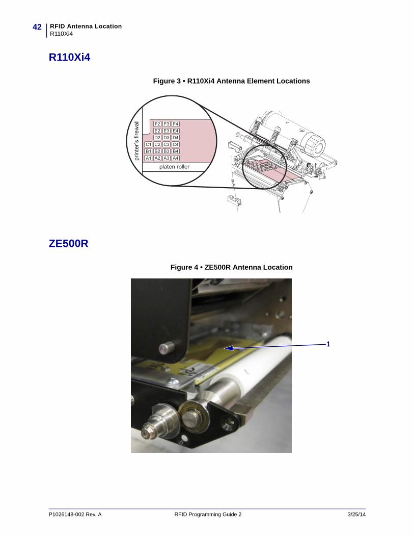
R110Xi4
Figure 3 • R110Xi4 Antenna Element Locations
ZE500R
Figure 4 • ZE500R Antenna Location
1
P1026148-002 Rev. A RFID Programming Guide 2 3/25/14

43RFID Antenna LocationRZ400 and RZ600
RZ400 and RZ600
Figure 5 • RZ400 and RZ600 Antenna Location
RP4T
Figure 6 • RP4T Antenna Location
1
1
3/25/14 RFID Programming Guide 2 P1026148-002 Rev. A

RFID Antenna LocationRP4T
44
Notes • ____________________________________________________________________
__________________________________________________________________________
__________________________________________________________________________
__________________________________________________________________________
__________________________________________________________________________
__________________________________________________________________________
__________________________________________________________________________
__________________________________________________________________________
__________________________________________________________________________
__________________________________________________________________________
P1026148-002 Rev. A RFID Programming Guide 2 3/25/14
6Troubleshooting
This section provides information about RFID operational errors that you might need to troubleshoot. For other types of problems, consult the User Guide for your printer.
3/25/14 RFID Programming Guide 2 P1026148-002 Rev. A
ContentsRFID Problems. . . . . . . . . . . . . . . . . . . . . . . . . . . . . . . . . . . . . . . . . . . . . . . . . . . . . . . . . 46RFID Error Codes and Messages . . . . . . . . . . . . . . . . . . . . . . . . . . . . . . . . . . . . . . . . . . 49
Error and Status Messages . . . . . . . . . . . . . . . . . . . . . . . . . . . . . . . . . . . . . . . . . . . . . 49Error Codes . . . . . . . . . . . . . . . . . . . . . . . . . . . . . . . . . . . . . . . . . . . . . . . . . . . . . . . . . 54
TroubleshootingRFID Problems
46
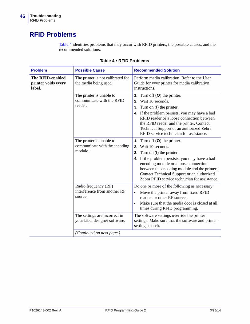
RFID Problems
Table 4 identifies problems that may occur with RFID printers, the possible causes, and the recommended solutions.
Table 4 • RFID Problems
Problem Possible Cause Recommended Solution
The RFID-enabled printer voids every label.
The printer is not calibrated for the media being used.
Perform media calibration. Refer to the User Guide for your printer for media calibration instructions.
The printer is unable to communicate with the RFID reader.
1. Turn off (O) the printer.2. Wait 10 seconds.3. Turn on (I) the printer.4. If the problem persists, you may have a bad
RFID reader or a loose connection between the RFID reader and the printer. Contact Technical Support or an authorized Zebra RFID service technician for assistance.
The printer is unable to communicate with the encoding module.
1. Turn off (O) the printer.2. Wait 10 seconds.3. Turn on (I) the printer.4. If the problem persists, you may have a bad
encoding module or a loose connection between the encoding module and the printer. Contact Technical Support or an authorized Zebra RFID service technician for assistance.
Radio frequency (RF) interference from another RF source.
Do one or more of the following as necessary:
• Move the printer away from fixed RFID readers or other RF sources.
• Make sure that the media door is closed at all times during RFID programming.
The settings are incorrect in your label designer software.
The software settings override the printer settings. Make sure that the software and printer settings match.
(Continued on next page.)
P1026148-002 Rev. A RFID Programming Guide 2 3/25/14

47TroubleshootingRFID Problems
The RFID-enabled printer voids every label.
(Continued from previous page.)
You are using an incorrect programming position, particularly if the tags being used are within printer specifications.
Do one or more of the following as necessary:
• Check the RFID programming position (see Using the Correct Programming Position on page 21), or the program position setting in your label designer software. If the position is incorrect, change the setting.
• Restore the RFID programming position back to the default value. See Restoring the Printer’s Default Programming Position on page 21.
You are sending RFID ZPL or SGD commands that are incorrect.
Check your label formats. See ZPL II Commands for RFID on page 59 or SGD Commands for RFID on page 101.
Low yields. Too many RFID tags per roll are voided.
The RFID labels are not within specifications for the printer, which means that the transponder is not in an area that can be programmed consistently.
Make sure that the labels meet transponder placement specifications for your printer. See http://www.zebra.com/transponders for transponder placement information.
Contact an authorized Zebra RFID reseller for more information.
Some RFID tags are more sensitive than others and may require special printer settings.
1. Verify that the printer is set for the correct write power.See http://www.zebra.com/transponders for the recommended power setting for each tag type.
2. If necessary, run the ^HR command to manually calibrate the transponder position.
3. If the problem persists, consider using a different tag type.
Contact an authorized Zebra RFID reseller for more information.
Incorrect read and write power levels for the RFID tag type.
Change the RFID read and write power levels (see View or Change RFID Read Power on page 30 or View or Change RFID Write Power on page 30).
Radio frequency (RF) interference from another RF source.
Do one or more of the following as necessary:
• Move the printer away from fixed RFID readers.
• Make sure that the media door is closed at all times during RFID programming.
The printer is using outdated printer firmware and reader firmware versions.
Go to http://www.zebra.com/firmware for updated firmware.
Table 4 • RFID Problems (Continued)
Problem Possible Cause Recommended Solution
3/25/14 RFID Programming Guide 2 P1026148-002 Rev. A
TroubleshootingRFID Problems
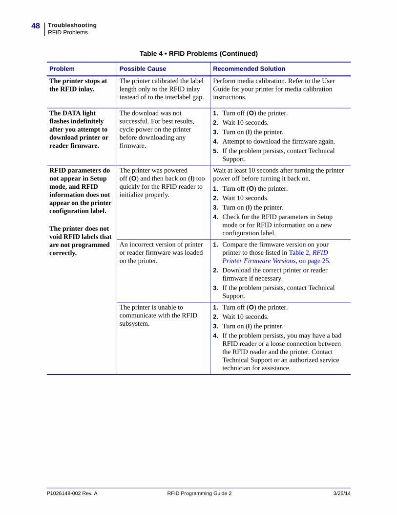
48
The printer stops at the RFID inlay.
The printer calibrated the label length only to the RFID inlay instead of to the interlabel gap.
Perform media calibration. Refer to the User Guide for your printer for media calibration instructions.
The DATA light flashes indefinitely after you attempt to download printer or reader firmware.
The download was not successful. For best results, cycle power on the printer before downloading any firmware.
1. Turn off (O) the printer.2. Wait 10 seconds.3. Turn on (I) the printer.4. Attempt to download the firmware again.5. If the problem persists, contact Technical
Support.
RFID parameters do not appear in Setup mode, and RFID information does not appear on the printer configuration label.
The printer does not void RFID labels that are not programmed correctly.
The printer was powered off (O) and then back on (I) too quickly for the RFID reader to initialize properly.
Wait at least 10 seconds after turning the printer power off before turning it back on.
1. Turn off (O) the printer.2. Wait 10 seconds.3. Turn on (I) the printer.4. Check for the RFID parameters in Setup
mode or for RFID information on a new configuration label.
An incorrect version of printer or reader firmware was loaded on the printer.
1. Compare the firmware version on your printer to those listed in Table 2, RFID Printer Firmware Versions, on page 25.
2. Download the correct printer or reader firmware if necessary.
3. If the problem persists, contact Technical Support.
The printer is unable to communicate with the RFID subsystem.
1. Turn off (O) the printer.2. Wait 10 seconds.3. Turn on (I) the printer.4. If the problem persists, you may have a bad
RFID reader or a loose connection between the RFID reader and the printer. Contact Technical Support or an authorized service technician for assistance.
Table 4 • RFID Problems (Continued)
Problem Possible Cause Recommended Solution
P1026148-002 Rev. A RFID Programming Guide 2 3/25/14

49TroubleshootingRFID Error Codes and Messages
RFID Error Codes and Messages
In the event of an RFID error, the printer does the following:
• displays an RFID error or status message on the second line of the RFID ERR STATUS control panel parameter
• returns RFID error codes to the RFID data log (see ^HL or ~HL on page 61 for more information about the RFID data log)
Table 5 provides the possible problems sorted by the error message, while Table 6 on page 54 provides these problems sorted by the error code.
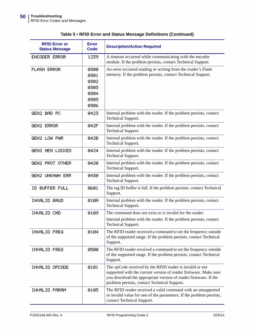
Error and Status Messages
Table 5 shows the possible error and status messages, the corresponding error codes, and the action required (if any).
Table 5 • RFID Error and Status Message Definitions
RFID Error or Status Message
Error Code
Description/Action Required
AFE NOT ON 0405 Internal problem with the reader. The Analog Front End is turned off. Contact Technical Support.
ANT. BAD/GONE 0503 The antenna is not connected, or the printer attempted to transmit on an antenna that did not pass the antenna detection.
BAD APP END ADD 0201 The RFID reader received a command to erase some part of the flash memory. This typically would happen during a reader firmware upgrade. Make sure that you download the appropriate version of reader firmware. If the problem persists, contact Technical Support.
BAD IMAGE CRC 0200 The RFID reader received a command to erase some part of the flash memory. This typically would happen during a reader firmware upgrade. Make sure that you download the appropriate version of reader firmware. If the problem persists, contact Technical Support.
COM ERROR 1235 The command echo was not found properly.
DATA AMOUNT ERR 0100 Two situations can result in this error:
• The data length in a message to the RFID reader from the printer is less than the number of arguments in the message.
• The data length is greater than the number of arguments. The reader will wait indefinitely until it receives all of the data specified in the data length field.
If the problem persists, contact Technical Support.
DATA AMOUNT ERR 1011 The packet length is larger than the maximum packet size.
DATA TOO LARGE 040B Internal problem with the reader. If the problem persists, contact Technical Support.
3/25/14 RFID Programming Guide 2 P1026148-002 Rev. A
TroubleshootingRFID Error Codes and Messages
50
ENCODER ERROR 1239 A timeout occurred while communicating with the encoder module. If the problem persists, contact Technical Support.
FLASH ERROR 0300
0301
0302
0303
0304
0305
0306
An error occurred reading or writing from the reader’s Flash memory. If the problem persists, contact Technical Support.
GEN2 BAD PC 0423 Internal problem with the reader. If the problem persists, contact Technical Support.
GEN2 ERROR 042F Internal problem with the reader. If the problem persists, contact Technical Support.
GEN2 LOW PWR 042B Internal problem with the reader. If the problem persists, contact Technical Support.
GEN2 MEM LOCKED 0424 Internal problem with the reader. If the problem persists, contact Technical Support.
GEN2 PROT OTHER 0420 Internal problem with the reader. If the problem persists, contact Technical Support.
GEN2 UNKNWN ERR 0430 Internal problem with the reader. If the problem persists, contact Technical Support.
ID BUFFER FULL 0601 The tag ID buffer is full. If the problem persists, contact Technical Support.
INVALID BAUD 010A Internal problem with the reader. If the problem persists, contact Technical Support.
INVALID CMD 0109 The command does not exist or is invalid for the reader.
Internal problem with the reader. If the problem persists, contact Technical Support.
INVALID FREQ 0104 The RFID reader received a command to set the frequency outside of the supported range. If the problem persists, contact Technical Support.
INVALID FREQ 0500 The RFID reader received a command to set the frequency outside of the supported range. If the problem persists, contact Technical Support.
INVALID OPCODE 0101 The opCode received by the RFID reader is invalid or not supported with the current version of reader firmware. Make sure you download the appropriate version of reader firmware. If the problem persists, contact Technical Support.
INVALID PARAM 0105 The RFID reader received a valid command with an unsupported or invalid value for one of the parameters. If the problem persists, contact Technical Support.
Table 5 • RFID Error and Status Message Definitions (Continued)
RFID Error or Status Message
Error Code
Description/Action Required
P1026148-002 Rev. A RFID Programming Guide 2 3/25/14

51TroubleshootingRFID Error Codes and Messages
INVALID PROTOC 0402 The RFID reader received a command for a protocol value that is not supported with the current version of reader firmware. Make sure you have the right tag type selected and that you are using a tag that is supported by your printer.
INVALID WR DATA 0408 If the first two bits are 0b00, then the tag ID must be 96 bits. Otherwise, the tag ID is 64 bits.
Make sure that the first two bits have the correct values, depending on the tag ID length.
LOCK ERROR 0403 The lock process failed during a write tag data. The write tag command passed, but the lock did not. This could indicate a bad tag.
Repeat the process with another RFID tag. Make sure that the tag is placed within the RF field.
MULTIPLE TAGS 1237 More than one RFID tag was detected in the RF field.
Make sure only one label is in the RF field and that another tag is not elsewhere in the field. Make sure that the labels meet transponder placement specifications.
NO DATA READ 0404 The RFID tag used failed or does not have the correct CRC.
Try to read a few other tags. If the problem persists, contact Technical Support.
NO PROTOCOL 0401 The RFID reader received a command to perform a protocol command, but no protocol was initially set. The reader powers up with no protocols set.
Make sure that you are using a transponder that is supported by your printer.
NO TAG
NO TAG FOUND
0400 Note • This error message varies by reader type.
No RFID tag was detected in the RF field. Several things can cause this error:
• No acceptable RFID tag is in the RF field. This can happen if an RFID label is present but the transponder is not placed correctly within the label or if the wrong tag type is used.
• The read/write power being used is too low.• The RFID tag is weak or dead.Retry with another RFID tag. Make sure that you are using a transponder that is supported by your printer. If the problem persists, contact Technical Support.
Table 5 • RFID Error and Status Message Definitions (Continued)
RFID Error or Status Message
Error Code
Description/Action Required
3/25/14 RFID Programming Guide 2 P1026148-002 Rev. A
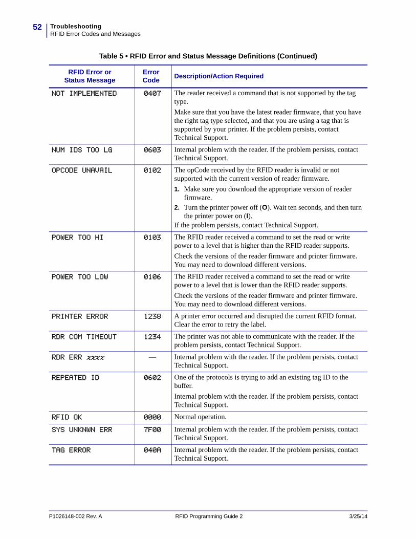
TroubleshootingRFID Error Codes and Messages
52
NOT IMPLEMENTED 0407 The reader received a command that is not supported by the tag type.
Make sure that you have the latest reader firmware, that you have the right tag type selected, and that you are using a tag that is supported by your printer. If the problem persists, contact Technical Support.
NUM IDS TOO LG 0603 Internal problem with the reader. If the problem persists, contact Technical Support.
OPCODE UNAVAIL 0102 The opCode received by the RFID reader is invalid or not supported with the current version of reader firmware.
1. Make sure you download the appropriate version of reader firmware.
2. Turn the printer power off (O). Wait ten seconds, and then turn the printer power on (I).
If the problem persists, contact Technical Support.
POWER TOO HI 0103 The RFID reader received a command to set the read or write power to a level that is higher than the RFID reader supports.
Check the versions of the reader firmware and printer firmware. You may need to download different versions.
POWER TOO LOW 0106 The RFID reader received a command to set the read or write power to a level that is lower than the RFID reader supports.
Check the versions of the reader firmware and printer firmware. You may need to download different versions.
PRINTER ERROR 1238 A printer error occurred and disrupted the current RFID format. Clear the error to retry the label.
RDR COM TIMEOUT 1234 The printer was not able to communicate with the reader. If the problem persists, contact Technical Support.
RDR ERR xxxx — Internal problem with the reader. If the problem persists, contact Technical Support.
REPEATED ID 0602 One of the protocols is trying to add an existing tag ID to the buffer.
Internal problem with the reader. If the problem persists, contact Technical Support.
RFID OK 0000 Normal operation.
SYS UNKNWN ERR 7F00 Internal problem with the reader. If the problem persists, contact Technical Support.
TAG ERROR 040A Internal problem with the reader. If the problem persists, contact Technical Support.
Table 5 • RFID Error and Status Message Definitions (Continued)
RFID Error or Status Message
Error Code
Description/Action Required
P1026148-002 Rev. A RFID Programming Guide 2 3/25/14
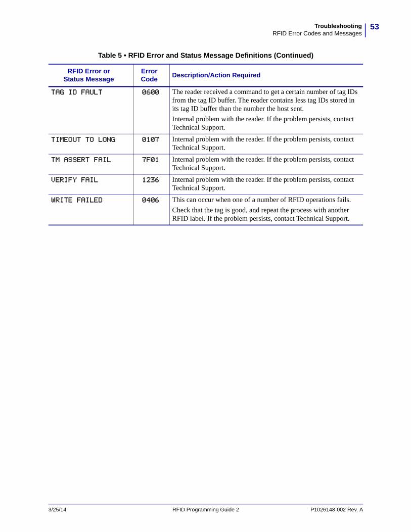
53TroubleshootingRFID Error Codes and Messages
TAG ID FAULT 0600 The reader received a command to get a certain number of tag IDs from the tag ID buffer. The reader contains less tag IDs stored in its tag ID buffer than the number the host sent.
Internal problem with the reader. If the problem persists, contact Technical Support.
TIMEOUT TO LONG 0107 Internal problem with the reader. If the problem persists, contact Technical Support.
TM ASSERT FAIL 7F01 Internal problem with the reader. If the problem persists, contact Technical Support.
VERIFY FAIL 1236 Internal problem with the reader. If the problem persists, contact Technical Support.
WRITE FAILED 0406 This can occur when one of a number of RFID operations fails.
Check that the tag is good, and repeat the process with another RFID label. If the problem persists, contact Technical Support.
Table 5 • RFID Error and Status Message Definitions (Continued)
RFID Error or Status Message
Error Code
Description/Action Required
3/25/14 RFID Programming Guide 2 P1026148-002 Rev. A

TroubleshootingRFID Error Codes and Messages
54
Error Codes
Table 6 shows the possible error codes, the corresponding error or status message, and the action required (if any). Numbers that appear in the format “RDR ERR xxxx” are not listed individually. See the first line of Table 6 for an explanation.
Table 6 • RFID Error Code Definitions
Error Code
RFID Error or Status Message
Description/Action Required
0000 RFID OK Normal operation.
0100 DATA AMOUNT ERR Two situations can result in this error:
• The data length in a message to the RFID reader from the printer is less than the number of arguments in the message.
• The data length is greater than the number of arguments. The reader will wait indefinitely until it receives all of the data specified in the data length field.
If the problem persists, contact Technical Support.
0101 INVALID OPCODE The opCode received by the RFID reader is invalid or not supported with the current version of reader firmware. Make sure you download the appropriate version of reader firmware. If the problem persists, contact Technical Support.
0102 OPCODE UNAVAIL The opCode received by the RFID reader is invalid or not supported with the current version of reader firmware.
1. Make sure you download the appropriate version of reader firmware.
2. Turn the printer power off (O). Wait ten seconds, and then turn the printer power on (I).
If the problem persists, contact Technical Support.
0103 POWER TOO HI The RFID reader received a command to set the read or write power to a level that is higher than the RFID reader supports.
Check the versions of the reader firmware and printer firmware. You may need to download different versions.
0104 INVALID FREQ The RFID reader received a command to set the frequency outside of the supported range. If the problem persists, contact Technical Support.
0105 INVALID PARAM The RFID reader received a valid command with an unsupported or invalid value for one of the parameters. If the problem persists, contact Technical Support.
0106 POWER TOO LOW The RFID reader received a command to set the read or write power to a level that is lower than the RFID reader supports.
Check the versions of the reader firmware and printer firmware. You may need to download different versions.
0107 TIMEOUT TO LONG Internal problem with the reader. If the problem persists, contact Technical Support.
P1026148-002 Rev. A RFID Programming Guide 2 3/25/14
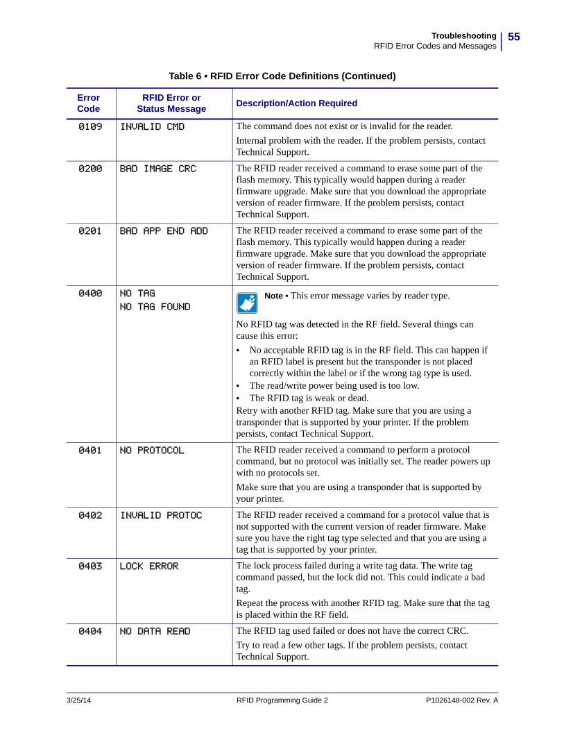
55TroubleshootingRFID Error Codes and Messages
0109 INVALID CMD The command does not exist or is invalid for the reader.
Internal problem with the reader. If the problem persists, contact Technical Support.
0200 BAD IMAGE CRC The RFID reader received a command to erase some part of the flash memory. This typically would happen during a reader firmware upgrade. Make sure that you download the appropriate version of reader firmware. If the problem persists, contact Technical Support.
0201 BAD APP END ADD The RFID reader received a command to erase some part of the flash memory. This typically would happen during a reader firmware upgrade. Make sure that you download the appropriate version of reader firmware. If the problem persists, contact Technical Support.
0400 NO TAG
NO TAG FOUNDNote • This error message varies by reader type.
No RFID tag was detected in the RF field. Several things can cause this error:
• No acceptable RFID tag is in the RF field. This can happen if an RFID label is present but the transponder is not placed correctly within the label or if the wrong tag type is used.
• The read/write power being used is too low.• The RFID tag is weak or dead.Retry with another RFID tag. Make sure that you are using a transponder that is supported by your printer. If the problem persists, contact Technical Support.
0401 NO PROTOCOL The RFID reader received a command to perform a protocol command, but no protocol was initially set. The reader powers up with no protocols set.
Make sure that you are using a transponder that is supported by your printer.
0402 INVALID PROTOC The RFID reader received a command for a protocol value that is not supported with the current version of reader firmware. Make sure you have the right tag type selected and that you are using a tag that is supported by your printer.
0403 LOCK ERROR The lock process failed during a write tag data. The write tag command passed, but the lock did not. This could indicate a bad tag.
Repeat the process with another RFID tag. Make sure that the tag is placed within the RF field.
0404 NO DATA READ The RFID tag used failed or does not have the correct CRC.
Try to read a few other tags. If the problem persists, contact Technical Support.
Table 6 • RFID Error Code Definitions (Continued)
Error Code
RFID Error or Status Message
Description/Action Required
3/25/14 RFID Programming Guide 2 P1026148-002 Rev. A
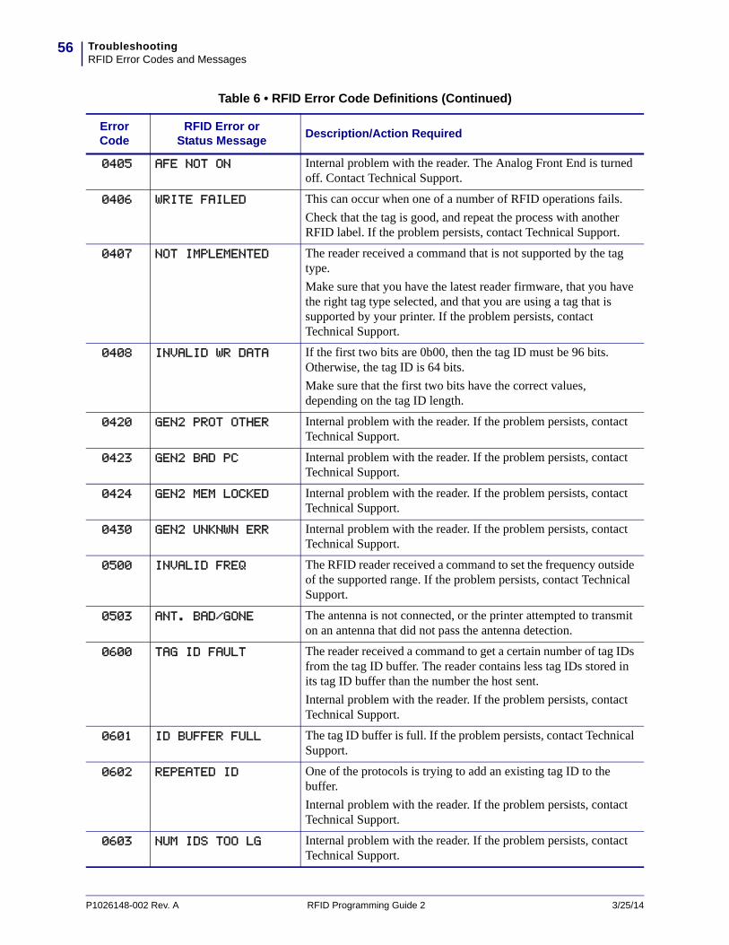
TroubleshootingRFID Error Codes and Messages
56
0405 AFE NOT ON Internal problem with the reader. The Analog Front End is turned off. Contact Technical Support.
0406 WRITE FAILED This can occur when one of a number of RFID operations fails.
Check that the tag is good, and repeat the process with another RFID label. If the problem persists, contact Technical Support.
0407 NOT IMPLEMENTED The reader received a command that is not supported by the tag type.
Make sure that you have the latest reader firmware, that you have the right tag type selected, and that you are using a tag that is supported by your printer. If the problem persists, contact Technical Support.
0408 INVALID WR DATA If the first two bits are 0b00, then the tag ID must be 96 bits. Otherwise, the tag ID is 64 bits.
Make sure that the first two bits have the correct values, depending on the tag ID length.
0420 GEN2 PROT OTHER Internal problem with the reader. If the problem persists, contact Technical Support.
0423 GEN2 BAD PC Internal problem with the reader. If the problem persists, contact Technical Support.
0424 GEN2 MEM LOCKED Internal problem with the reader. If the problem persists, contact Technical Support.
0430 GEN2 UNKNWN ERR Internal problem with the reader. If the problem persists, contact Technical Support.
0500 INVALID FREQ The RFID reader received a command to set the frequency outside of the supported range. If the problem persists, contact Technical Support.
0503 ANT. BAD/GONE The antenna is not connected, or the printer attempted to transmit on an antenna that did not pass the antenna detection.
0600 TAG ID FAULT The reader received a command to get a certain number of tag IDs from the tag ID buffer. The reader contains less tag IDs stored in its tag ID buffer than the number the host sent.
Internal problem with the reader. If the problem persists, contact Technical Support.
0601 ID BUFFER FULL The tag ID buffer is full. If the problem persists, contact Technical Support.
0602 REPEATED ID One of the protocols is trying to add an existing tag ID to the buffer.
Internal problem with the reader. If the problem persists, contact Technical Support.
0603 NUM IDS TOO LG Internal problem with the reader. If the problem persists, contact Technical Support.
Table 6 • RFID Error Code Definitions (Continued)
Error Code
RFID Error or Status Message
Description/Action Required
P1026148-002 Rev. A RFID Programming Guide 2 3/25/14
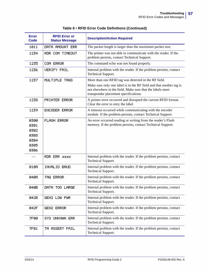
57TroubleshootingRFID Error Codes and Messages
1011 DATA AMOUNT ERR The packet length is larger than the maximum packet size.
1234 RDR COM TIMEOUT The printer was not able to communicate with the reader. If the problem persists, contact Technical Support.
1235 COM ERROR The command echo was not found properly.
1236 VERIFY FAIL Internal problem with the reader. If the problem persists, contact Technical Support.
1237 MULTIPLE TAGS More than one RFID tag was detected in the RF field.
Make sure only one label is in the RF field and that another tag is not elsewhere in the field. Make sure that the labels meet transponder placement specifications.
1238 PRINTER ERROR A printer error occurred and disrupted the current RFID format. Clear the error to retry the label.
1239 ENCODER ERROR A timeout occurred while communicating with the encoder module. If the problem persists, contact Technical Support.
0300
0301
0302
0303
0304
0305
0306
FLASH ERROR An error occurred reading or writing from the reader’s Flash memory. If the problem persists, contact Technical Support.
— RDR ERR xxxx Internal problem with the reader. If the problem persists, contact Technical Support.
010A INVALID BAUD Internal problem with the reader. If the problem persists, contact Technical Support.
040A TAG ERROR Internal problem with the reader. If the problem persists, contact Technical Support.
040B DATA TOO LARGE Internal problem with the reader. If the problem persists, contact Technical Support.
042B GEN2 LOW PWR Internal problem with the reader. If the problem persists, contact Technical Support.
042F GEN2 ERROR Internal problem with the reader. If the problem persists, contact Technical Support.
7F00 SYS UNKNWN ERR Internal problem with the reader. If the problem persists, contact Technical Support.
7F01 TM ASSERT FAIL Internal problem with the reader. If the problem persists, contact Technical Support.
Table 6 • RFID Error Code Definitions (Continued)
Error Code
RFID Error or Status Message
Description/Action Required
3/25/14 RFID Programming Guide 2 P1026148-002 Rev. A

TroubleshootingRFID Error Codes and Messages
58
Notes • ____________________________________________________________________
__________________________________________________________________________
__________________________________________________________________________
__________________________________________________________________________
__________________________________________________________________________
__________________________________________________________________________
__________________________________________________________________________
__________________________________________________________________________
__________________________________________________________________________
__________________________________________________________________________
P1026148-002 Rev. A RFID Programming Guide 2 3/25/14

7ZPL II Commands for RFID
This section contains the ZPL II commands for RFID-specific applications.
For non-RFID ZPL commands, refer to the Programming Guide for ZPL, ZBI, Set-Get-Do, Mirror, and WML. A copy of the manual is located on the User CD that came with your printer, or you can download a copy from http://www.zebra.com/manuals.
3/25/14 RFID Programming Guide 2 P1026148-002 Rev. A
ContentsZPL Overview. . . . . . . . . . . . . . . . . . . . . . . . . . . . . . . . . . . . . . . . . . . . . . . . . . . . . . . . . . 60
^HL or ~HL Return RFID Data Log to Host . . . . . . . . . . . . . . . . . . . . . . . . . . . . . . . 61
^HR Calibrate RFID Transponder Position . . . . . . . . . . . . . . . . . . . . . . . . . . . . . . . . . . 62
^HV Host Verification . . . . . . . . . . . . . . . . . . . . . . . . . . . . . . . . . . . . . . . . . . . . . . . . . . . 68
^MM Print Mode . . . . . . . . . . . . . . . . . . . . . . . . . . . . . . . . . . . . . . . . . . . . . . . . . . . . . . . 69
^RB Define EPC Data Structure . . . . . . . . . . . . . . . . . . . . . . . . . . . . . . . . . . . . . . . . . . 71
^RF Read or Write RFID Format . . . . . . . . . . . . . . . . . . . . . . . . . . . . . . . . . . . . . . . . . . 73
^RI Get RFID Tag ID. . . . . . . . . . . . . . . . . . . . . . . . . . . . . . . . . . . . . . . . . . . . . . . . . . . 76
^RM Enable RFID Motion. . . . . . . . . . . . . . . . . . . . . . . . . . . . . . . . . . . . . . . . . . . . . . . . 80
~RO Reset Advanced Counters . . . . . . . . . . . . . . . . . . . . . . . . . . . . . . . . . . . . . . . . . . . 81
^RQ Quick Write EPC Data and Passwords . . . . . . . . . . . . . . . . . . . . . . . . . . . . . . . . . 83
^RR Specify RFID Retries for a Block . . . . . . . . . . . . . . . . . . . . . . . . . . . . . . . . . . . . . . 85
^RS Set Up RFID Parameters . . . . . . . . . . . . . . . . . . . . . . . . . . . . . . . . . . . . . . . . . . . . 87
~RV Report RFID Encoding Results . . . . . . . . . . . . . . . . . . . . . . . . . . . . . . . . . . . . . . . 95
^RW Set RF Power Levels for Read and Write . . . . . . . . . . . . . . . . . . . . . . . . . . . . . . . 96
^RZ Set RFID Tag Password and Lock Tag . . . . . . . . . . . . . . . . . . . . . . . . . . . . . . . . . 98

ZPL II Commands for RFIDZPL Overview
60
P1026148-002 Rev. A RFID Programming Guide 2 3/25/14
ZPL Overview
In addition to reading or encoding RFID tags, the RFID ZPL commands also provide for RFID exception handling, such as setting the number of read/write retries before declaring a transponder defective (set with ^RR) or setting the number of labels that will be attempted if an error occurs (set with ^RS).
For example, if an RFID label fails to program correctly or if the transponder cannot be detected, the printer ejects the label and prints VOID across it. The printer will try to print another label with the same data and format for the number of RFID labels specified by the ^RS command. If the problem persists, the printer follows the error handling instructions specified by the ^RS command: the printer may remove the problematic format from the print queue and proceed with the next format (if one exists in the buffer), or it may place the printer in Pause or Error mode.
61ZPL II Commands for RFID^HL or ~HL
3/25/14 RFID Programming Guide 2 P1026148-002 Rev. A
^HL or ~HL – Return RFID Data Log to HostDescription The printer continually logs RFID data and stores it in the printer’s RAM. This command requests that the RFID data log be returned to the host computer, to clear the current data log, and to restart data recording.
In the log, RFID data displays in this format:
C,EEEE,DDDDDDDDDDDDDDDDDDDDDDDD
where C = the RFID operation (R = read, W = write, L = lock, S = RFID settings,
E = log file reset)
EEEE = the RFID error code (see RFID Error Codes and Messages on page 49) or the RFID setting (RPWR = read power, WPWR = write power, ANT = antenna, PPOS = program position, FFFF = indicates that the log file was reset)
DDDDDDDDDDDDDDDDDDDDDDDD = data read or written
Format ^HL or ~HL
Comments
• Data is shown in the format specified by the ^RFW command (ASCII, Hex, or EPC).
• If the log exceeds 64K (approximately 2000 operations), the data log is cleared automatically, and data recording restarts. When this happens, the following appears in the log:
E,FFFF,Logfile automatically reset
• If the printer loses power, the log is lost. If the log results are important to you, retrieve the information frequently.
ZPL II Commands for RFID^HR
62
^HR – Calibrate RFID Transponder Position
Description Use this command to initiate transponder calibration for RFID media that does not meet the transponder placement specifications for the printer. During the process, the printer moves the media, calibrates the RFID transponder position, and determines the optimal programming position for the RFID media being used. For the R110Xi4 printer, this command also selects the best antenna element and read/write power level for the media.
Results of the transponder calibration are returned to the host computer. The RUN option in the RFID TAG CALIB control panel parameter and the "RUN" option in the rfid.tag.calibrate SGD command perform the same calibration but do not create a results table.
To return to the printer’s default programming position at any time, use one of the following:
• the RESTORE option in the RFID TAG CALIB control panel parameter (see Calibrate RFID Transponder Position on page 29)
• the "RESTORE" option in the rfid.tag.calibrate SGD command (see rfid.tag.calibrate on page 109)
Format ^HRa,b,c,d,e
Important • Before using this command, see Using the Correct Programming Position on page 21. Running this command may not be the best option for your printer.
Parameters Details
a = start string This parameter specifies the user text to appear before the results table.
Accepted values: any string less than 65 characters
Default value: start
b = end string This parameter specifies the user text to appear after the results table.
Accepted values: any string less than 65 characters
Default value: end
P1026148-002 Rev. A RFID Programming Guide 2 3/25/14
63ZPL II Commands for RFID^HR
c = start position This parameter specifies the start position of the calibration range. All numeric values are in millimeters. Forward or backward designations assume that the label's initial position is with the leading edge at the print line.
Accepted Values: Forward: F0 to Fxxx (where xxx is the label length in millimeters or 999,
whichever is less)The printer feeds the label forward for the specified distance and then begins transponder calibration.
Backward: B0 to B30 (Not valid on the RP4T printer.)The printer backfeeds the label for the specified distance and then begins transponder calibration. Allow at least 1.25 in. (32 mm) of empty media liner to extend out of the front of the printer.
Default value:
For the R110Xi4: B20 The printer backfeeds 20 mm before starting transponder calibration.
For all other supported printers: F0 The printer moves the media to the start position relative to the leading edge of the label and then performs the RFID tag calibration.
d = end position This parameter specifies the end position of the calibration range (last program position to check). All numeric values are in millimeters. Forward or backward designations assume that the label's initial position is with the leading edge at the print line.
Accepted Values: Forward: F0 to Fxxx (where xxx is the label length in millimeters or 999,
whichever is less)The printer performs transponder calibration until it reaches the specified end position and then ends the process.
Backward: B0 to B30 (Not valid on the RP4T printer.)The printer performs transponder calibration until it reaches the specified end position and then ends the process. Valid only with a backward start position that is greater than the end position.
A = Automatic (valid only on the R110Xi4 printer)The printer automatically ends the transponder calibration process after successfully reading and encoding a consecutive range of 5 mm on the label.
Default value:
For the R110Xi4: A For all other supported printers: Label length as shown on the printer
configuration label
Parameters Details
3/25/14 RFID Programming Guide 2 P1026148-002 Rev. A

ZPL II Commands for RFID^HR
64
e = antenna and read/write power level detection
Note • This parameter is valid only on the R110Xi4 printer.
This parameter selects the option to select the antenna and read/write power level automatically.
Accepted Values: A = Automatic. The printer automatically scans through the antennas and
read/write power during calibration.
M = Manual. The printer uses the current antenna and read/write power level settings.
Default value: A
Parameters Details
P1026148-002 Rev. A RFID Programming Guide 2 3/25/14
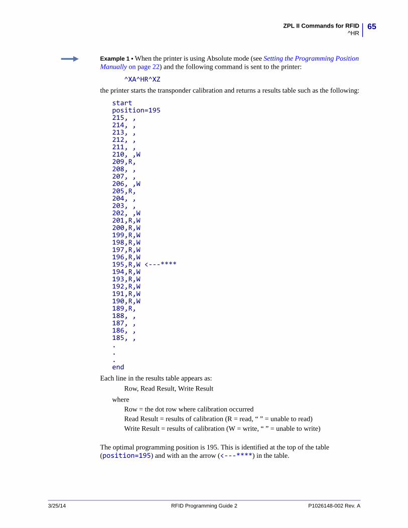
65ZPL II Commands for RFID^HR
Example 1 • When the printer is using Absolute mode (see Setting the Programming Position Manually on page 22) and the following command is sent to the printer:
^XA^HR^XZthe printer starts the transponder calibration and returns a results table such as the following:
startposition=195215, , 214, , 213, , 212, , 211, , 210, ,W209,R, 208, , 207, , 206, ,W205,R, 204, , 203, , 202, ,W201,R,W200,R,W199,R,W198,R,W197,R,W196,R,W195,R,W <---****194,R,W193,R,W192,R,W191,R,W190,R,W189,R, 188, , 187, , 186, , 185, , ...end
Each line in the results table appears as:
Row, Read Result, Write Result
where Row = the dot row where calibration occurred Read Result = results of calibration (R = read, “ ” = unable to read)Write Result = results of calibration (W = write, “ ” = unable to write)
The optimal programming position is 195. This is identified at the top of the table (position=195) and with an the arrow (<---****) in the table.
3/25/14 RFID Programming Guide 2 P1026148-002 Rev. A

ZPL II Commands for RFID^HR
66
Example 2 • When the printer is using Relative mode (see Setting the Programming Position Manually on page 22) and the following command is sent to the printer:
^HRstart,end,B20,F42,Mthe printer starts the transponder calibration and returns a results table such as the following:
startposition=F0 MMleading edgeB20, , B19, , B18, , B17, , …B8, , B7, , B6, , B5, , B4,R,WB3,R,WB2,R,WB1,R,WF0,R,W<---**** F0 MMF1,R,WF2,R,WF3,R,WF4, , F5, , F6, , F7, , F8, , F9, , F10, , …F38, , F39, , F40, , F41, , F42, , trailing edgeend
Each line in the results table appears as:
Row, Read Result, Write Result
where Row = the position from the leading edge of the label where calibration occurred Read Result = results of calibration (R = read, “ ” = unable to read)Write Result = results of calibration (W = write, “ ” = unable to write)
The optimal programming position is F0 (program with the leading edge of the label at the print line). This is identified at the top of the table (position=F0 MM) and with an the arrow (<---****) in the table.
P1026148-002 Rev. A RFID Programming Guide 2 3/25/14
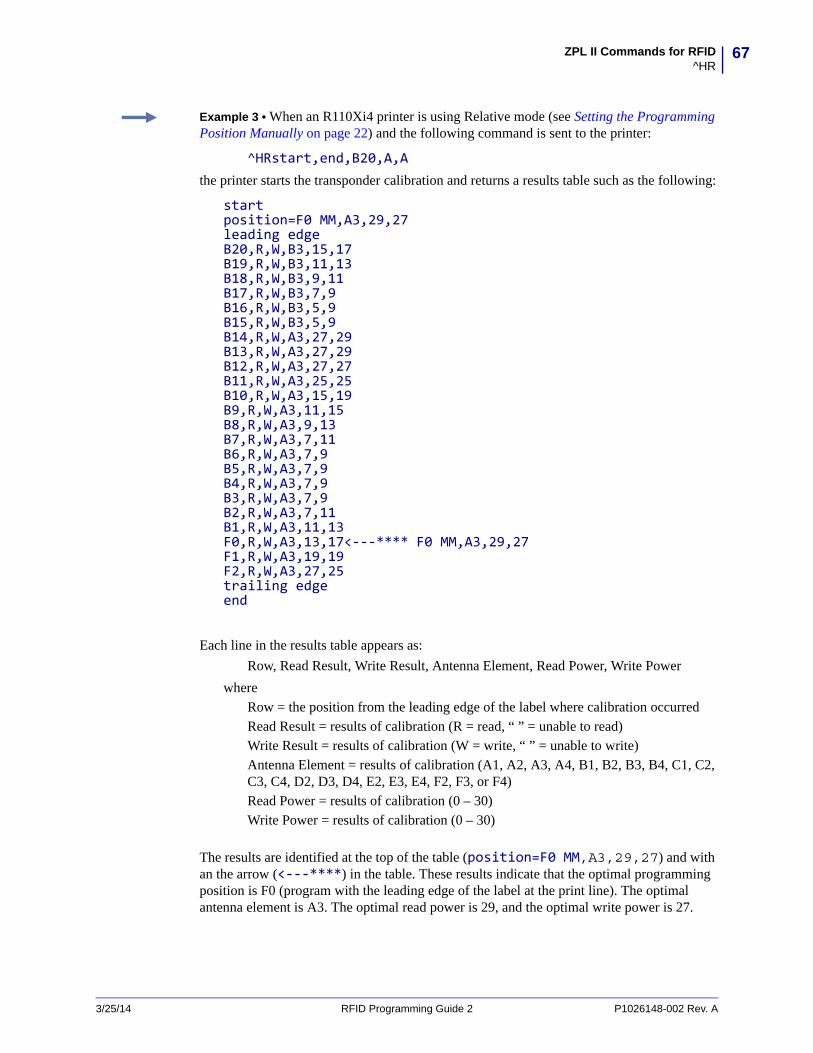
67ZPL II Commands for RFID^HR
Example 3 • When an R110Xi4 printer is using Relative mode (see Setting the Programming Position Manually on page 22) and the following command is sent to the printer:
^HRstart,end,B20,A,Athe printer starts the transponder calibration and returns a results table such as the following:
startposition=F0 MM,A3,29,27leading edgeB20,R,W,B3,15,17B19,R,W,B3,11,13B18,R,W,B3,9,11B17,R,W,B3,7,9B16,R,W,B3,5,9B15,R,W,B3,5,9B14,R,W,A3,27,29B13,R,W,A3,27,29B12,R,W,A3,27,27B11,R,W,A3,25,25B10,R,W,A3,15,19B9,R,W,A3,11,15B8,R,W,A3,9,13B7,R,W,A3,7,11B6,R,W,A3,7,9B5,R,W,A3,7,9B4,R,W,A3,7,9B3,R,W,A3,7,9B2,R,W,A3,7,11B1,R,W,A3,11,13F0,R,W,A3,13,17<---**** F0 MM,A3,29,27F1,R,W,A3,19,19F2,R,W,A3,27,25trailing edgeend
Each line in the results table appears as:
Row, Read Result, Write Result, Antenna Element, Read Power, Write Power
where Row = the position from the leading edge of the label where calibration occurred Read Result = results of calibration (R = read, “ ” = unable to read)Write Result = results of calibration (W = write, “ ” = unable to write)Antenna Element = results of calibration (A1, A2, A3, A4, B1, B2, B3, B4, C1, C2, C3, C4, D2, D3, D4, E2, E3, E4, F2, F3, or F4)Read Power = results of calibration (0 – 30)Write Power = results of calibration (0 – 30)
The results are identified at the top of the table (position=F0 MM,A3,29,27) and with an the arrow (<---****) in the table. These results indicate that the optimal programming position is F0 (program with the leading edge of the label at the print line). The optimal antenna element is A3. The optimal read power is 29, and the optimal write power is 27.
3/25/14 RFID Programming Guide 2 P1026148-002 Rev. A

ZPL II Commands for RFID^HV
68
P1026148-002 Rev. A RFID Programming Guide 2 3/25/14
^HV – Host VerificationDescription Use this command to return data from specified fields, along with an optional ASCII header, to the host computer. You can use this command with any field that has been assigned a number with the ^RT command or with the ^FN and ^RF commands.
Format ^HV#,n,h,t,a
This table identifies the parameters for this format:
Parameters Details
# = field number specified with another command
The value assigned to this parameter should be the same as the one used in another command.
Accepted Values: 0 to 9999Default Value: 0
n = number of bytes to be returned
Accepted Values: 1 to 256Default Value: 64
h = header to be returned with the data
Delimiter characters terminate the string. This field is Field Hex (^FH) capable.
Accepted Values: 0 to 3072 bytesDefault Value: no header
t = termination This field is Field Hex (^FH) capable.
Accepted Values: 0 to 3072 characters
a = command applies to When ^PQ is greater than 1, send one response for a label format or one for every label printed.
Accepted Values: F = Format
L = Label
Default Value: F
Example • The following code:
^XA...^FH_^HV0,8,EPC[,]_0D_0A,L^FS^PQ2^XZ
Would return data such as this:
EPC[12345678]EPC[55554444]
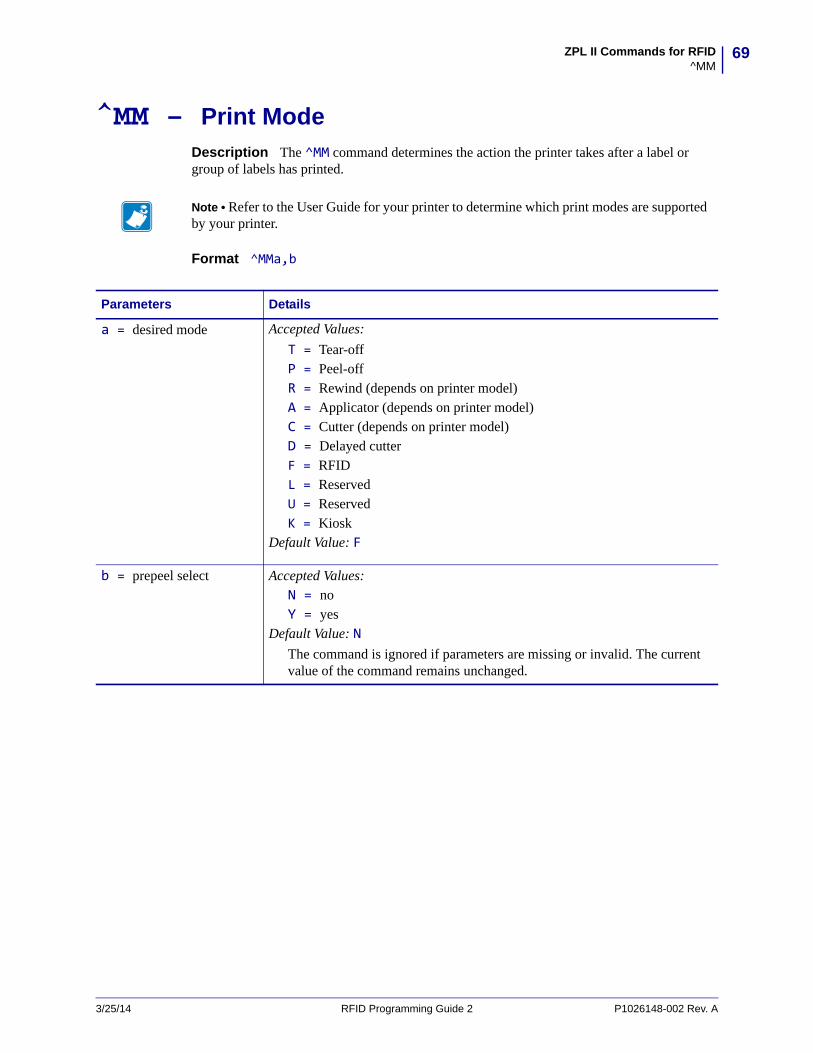
69ZPL II Commands for RFID^MM
^MM – Print ModeDescription The ^MM command determines the action the printer takes after a label or group of labels has printed.
Format ^MMa,b
Note • Refer to the User Guide for your printer to determine which print modes are supported by your printer.
Parameters Details
a = desired mode Accepted Values:
T = Tear-offP = Peel-offR = Rewind (depends on printer model)A = Applicator (depends on printer model) C = Cutter (depends on printer model)D = Delayed cutter F = RFIDL = Reserved U = Reserved K = Kiosk
Default Value: F
b = prepeel select Accepted Values: N = no Y = yes
Default Value: NThe command is ignored if parameters are missing or invalid. The current value of the command remains unchanged.
3/25/14 RFID Programming Guide 2 P1026148-002 Rev. A

ZPL II Commands for RFID^MM
70
This list identifies the different modes of operation:
• Tear-off — after printing, the label advances so the web is over the tear bar. The label, with liner attached, can be torn off manually.
• Peel-off — after printing, the label moves forward and activates a Label Available Sensor. Printing stops until the label is manually removed from the printer.
Power Peel – liner automatically rewinds using an optional internal rewind spindle.
Value Peel – liner feeds down the front of the printer and is manually removed.
Prepeel – after each label is manually removed, the printer feeds the next label forward to prepeel a small portion of the label away from the liner material. The printer then backfeeds and prints the label. The prepeel feature assists in the proper peel operation of some media types.
• Rewind — the label and liner are rewound on an (optional) external rewind device. The next label is positioned under the printhead (no backfeed motion).
• Applicator — when used with an application device, the label move far enough forward to be removed by the applicator and applied to an item. This applies only to printers that have applicator ports and that are being used in a print-and-apply system.
• Cutter — after printing, the media feeds forward and is automatically cut into predetermined lengths.
• Delayed cutter — When the printer is in the Delayed Cut PRINT MODE, it will cut the label when it receives the ~JK (Delayed Cut) command. To activate the ~JK command, the printer's PRINT MODE must be set to Delayed Cut and there must be a label waiting to be cut. When the printer is not in the Delayed Cut PRINT MODE, the printer will not cut the label when it receives the ~JK command.
The Delayed Cut feature can be activated:
• through PRINT MODE on the printer’s control panel
• with a ^MMD command
• RFID — increases throughput time when printing batches of RFID labels by eliminating backfeed between labels.
Comments Be sure to select the appropriate value for the print mode being used to avoid unexpected results.
Note • Send ~JK in a separate file - it cannot be sent at the end of a set of commands.
P1026148-002 Rev. A RFID Programming Guide 2 3/25/14
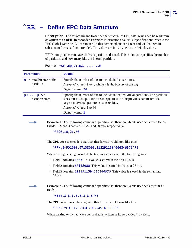
71ZPL II Commands for RFID^RB
^RB – Define EPC Data StructureDescription Use this command to define the structure of EPC data, which can be read from or written to an RFID transponder. For more information about EPC specifications, refer to the EPC Global web site. All parameters in this command are persistent and will be used in subsequent formats if not provided. The values are initially set to the default values.
RFID transponders can have different partitions defined. This command specifies the number of partitions and how many bits are in each partition.
Format ^RBn,p0,p1,p2, ..., p15
Parameters Details
n = total bit size of the partitions
Specify the number of bits to include in the partitions.
Accepted values: 1 to n, where n is the bit size of the tag.
Default value: 96p0 ... p15 =
partition sizesSpecify the number of bits to include in the individual partitions. The partition sizes must add up to the bit size specified for the previous parameter. The largest individual partition size is 64 bits.
Accepted values: 1 to 64
Default value: 1
Example 1 • The following command specifies that there are 96 bits used with three fields. Fields 1, 2, and 3 contain 10, 26, and 60 bits, respectively.
^RB96,10,26,60
The ZPL code to encode a tag with this format would look like this:
^RFW,E^FD1000.67108000.1122921504606846976^FS
When the tag is being encoded, the tag stores the data in the following way:
• Field 1 contains 1000. This value is stored in the first 10 bits
• Field 2 contains 67108000. This value is stored in the next 26 bits.
• Field 3 contains 1122921504606846976. This value is stored in the remaining 60 bits.
Example 2 • The following command specifies that there are 64 bits used with eight 8-bit fields.
^RB64,8,8,8,8,8,8,8,8^FS
The ZPL code to encode a tag with this format would look like this:
^RFW,E^FD1.123.160.200.249.6.1.0^FS
When writing to the tag, each set of data is written in its respective 8-bit field.
3/25/14 RFID Programming Guide 2 P1026148-002 Rev. A
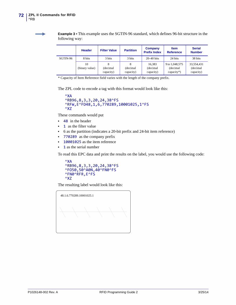
ZPL II Commands for RFID^RB
72
Example 3 • This example uses the SGTIN-96 standard, which defines 96-bit structure in the following way:
The ZPL code to encode a tag with this format would look like this:
^XA^RB96,8,3,3,20,24,38^FS^RFW,E^FD48,1,6,770289,10001025,1^FS^XZ
These commands would put
• 48 in the header• 1 as the filter value• 6 as the partition (indicates a 20-bit prefix and 24-bit item reference)• 770289 as the company prefix• 10001025 as the item reference • 1 as the serial number
To read this EPC data and print the results on the label, you would use the following code:
^XA^RB96,8,3,3,20,24,38^FS^FO50,50^A0N,40^FN0^FS^FN0^RFR,E^FS^XZ
The resulting label would look like this:
Header Filter Value PartitionCompany
Prefix IndexItem
ReferenceSerial
Number
SGTIN-96 8 bits 3 bits 3 bits 20–40 bits 24 bits 38 bits
10 (binary value)
8 (decimal capacity)
8 (decimal capacity)
16,383(decimal capacity)
9 to 1,048,575 (decimal
capacity*)
33,554,431 (decimal capacity)
* Capacity of Item Reference field varies with the length of the company prefix.
48.1.6.770289.10001025.1
P1026148-002 Rev. A RFID Programming Guide 2 3/25/14

73ZPL II Commands for RFID^RF
^RF – Read or Write RFID FormatDescription Use this command to read or write to (encode) an RFID tag. When using this command to read a tag, you may use a field variable to print the tag data on the label or to return the data to the host. See Create and Send an RFID Label Format on page 34 for examples that use a field variable. See Gen 2 Memory Map on page 14 to see how information is stored on a Gen 2 tag.
Format ^RFo,f,b,n,m
Parameters Details
o = operation Specifies the action to be performed.
Accepted Values:
W = write to (encode) the tag
R = read the tag
P = read password (Not supported on all printers.)
S = specify the access password*
* Requires V53.17.20 or later.
Default Value: W
f = format Accepted Values:
A = ASCII
H = Hexadecimal
E = EPC (ensure proper setup with the ^RB command)
Default Value: H
3/25/14 RFID Programming Guide 2 P1026148-002 Rev. A

ZPL II Commands for RFID^RF
74
b = password
OR
b = starting block number
What you specify for this parameter depends on what you enter for other parameters.
n = number of bytes to read or write
Specifies the number of bytes to read or write.
When E is specified for the memory bank parameter, this value is not required.
Accepted Values: 1 to n, where n is the maximum number of bytes for the tag.
Default Value: 1
Parameters Details
If the Operation parameter value is...
Then...
W Note • When the memory bank parameter is set to E (EPC 96-bit), this value is always set to 2.
Accepted Values: • P, which indicates that an access password, a kill
password, or both follow in a ^FD command. Each password must be 8 hex characters. If the password is omitted, it is not written. An access password is used in subsequent lock commands in the format.
• 0 to n, which specifies the 16-bit starting block number, where n is the maximum number of blocks for the bank specified in the memory bank parameter.
Default Value: 0
R Note • When the memory bank parameter is set to E (EPC 96-bit), this value is always set to 2.
Accepted Values: • 0 to n, which specifies the 16-bit starting block number,
where n is the maximum number of blocks for the bank specified in the memory bank parameter.
Default Value: 0
S This parameter must be P and must be followed by the access password in a ^FD command.
P This parameter specifies which password to read.
Accepted Values: • K=kill password• A=access passwordDefault Value: K
P1026148-002 Rev. A RFID Programming Guide 2 3/25/14
75ZPL II Commands for RFID^RF
m = memory bank Specifies the Gen 2 memory bank. See Gen 2 Memory Map on page 14 for more information about Gen 2 memory.
Accepted Values:
E = EPC 96-bit (When writing data, this parameter performs the operation on Gen 2 bit address 20h and accesses 12 bytes of the EPC memory bank. When reading data, this parameter reads the amount of data specified in the PC bits on the tag.)
0 = Reserved
1 = EPC
2 = TID (Tag ID)
3 = User
Default Value: E
Parameters Details
Example 1 • This example encodes 96-bit data in ASCII format.
^XA^RS8^RFw,a^FD00 my data^FS^XZ
Example 2 • This example encodes 96-bit EPC data, as specified by the ^RB command.
^XA^RB96,8,3,3,20,24,38^RFw,e^FD16,3,5,78742,146165,1234567891^FS^XZ
Example 3 • This example encodes 4 bytes of hexadecimal formatted data, starting in block 3 of Gen 2 EPC bank 1.
^XA^RS8^RFW,H,3,4,1^FD11112222^FS^XZ
Example 4 • This example reads the extended Gen 2 tag ID (TID), which is not read by the ^RI command, and returns the results to the host computer. The results are labeled with the header “8-byte Tag ID Data.”
^XA^RS8^RFR,H,0,8,2^FN1^FS^HV1,,8-byte Tag ID Data:^FS^XZ
3/25/14 RFID Programming Guide 2 P1026148-002 Rev. A
ZPL II Commands for RFID^RI
76
P1026148-002 Rev. A RFID Programming Guide 2 3/25/14
^RI – Get RFID Tag IDDescription This command returns the 32-bit tag ID (TID) for the tag. If your Gen 2 tag supports TID data beyond 32 bits, see ^RF on page 73 to access the TID memory bank. The data can be sent back to the host via the ^HV command.
Format ^RIa,b,c,d
Parameters Details
a = number to be assigned to the field
Accepted values: 0 to 9999
Default value: 0
b = specify data order Not used.
c = number of retries Accepted values: 0 to 10
Default value: 0
d = motion Accepted values:
0 = Feed label after writing
1 = No feed after writing (other ZPL commands may cause a feed)
Default value: 0
Example • This example reads a tag ID, prints it on a label, and sends string Tag ID:xxxxxxxx to the host. The data read will go into the ^FN0 location of the format. The printer will retry the command five times, if necessary.
^XA^FO20,120^A0N,60^FN0^FS^RI0,,5^FS^HV0,,Tag ID:^FS^XZ
77ZPL II Commands for RFID^RL
^RL – Lock/Unlock RFID Tag MemoryThe ^RL command has two distinct formats and functions:
• ^RLM – Lock/Unlock the Specified Memory BankLocks a password or an entire memory bank in a writeable or unwriteable state. These locks/unlocks can be permanent or reversible.
• ^RLB – Permanently Lock Specified Memory SectionsLocks blocks of user memory in an unwriteable state.
^RLM – Lock/Unlock the Specified Memory Bank
Description The ^RLM command locks/unlocks the specified password or memory bank on an RFID tag. You can use this command to do the following:
• lock individual passwords, thereby preventing or allowing subsequent reads or writes of that password
• lock individual memory banks, thereby preventing or allowing subsequent writes to those banks
• Permanently lock (permalock) the lock status for a password or memory bank
Format ^RLM,k,a,e,u
Important • Please note the following:
• This command is invalid on the RP4T printer. • Supported printers must use firmware version V53.17.20 or later, and the reader firmware
must be version 20120123 or later.• ^RL must not be used in conjunction with ^RZ on page 98. Be consistent with use of one
locking method or the other.
Parameters Details
k = kill password function
Accepted Values: U = unlock the kill password*
L = lock the kill password*
O = permanently unlock (Open) the kill password
P = permanently lock (Protected) the kill password
a = access password function
Accepted Values: U = unlock the access password*
L = lock the access password*
O = permanently unlock (Open) the access password
P = permanently lock (Protected) the access password
* The access password must be set to something other than the default of 00000000 to use this value. See Example 4 on page 79 for an example.
3/25/14 RFID Programming Guide 2 P1026148-002 Rev. A

ZPL II Commands for RFID^RL
78
^RLB – Permanently Lock Specified Memory Sections
Description The ^RLB command permanently locks (permalocks) one or more sections (individual sub-portions) in a tag’s user memory. The section sizes for each tag is defined by the tag manufacturer.
Format ^RLB,s,n
e = EPC memory bank function
Accepted Values: U = unlock the EPC memory bank*
L = lock the EPC memory bank*
O = permanently unlock (Open) the EPC memory bank
P = permanently lock (Protected) the EPC memory bank
u = USER memory bank function
Accepted Values: U = unlock the USER memory bank*
L = lock the USER password bank*
O = permanently unlock (Open) the USER memory bank
P = permanently lock (Protected) the USER memory bank
Parameters Details
* The access password must be set to something other than the default of 00000000 to use this value. See Example 4 on page 79 for an example.
Parameters Details
s = starting section Specify the starting section of memory to lock.
n = number of sections Specify the number of sections to lock.
Example 1 • The following command locks all memory banks using a previously specified access password.
^RLM,L,L,L,L^FS
Example 2 • The following command locks the user memory banks using a previously specified access password.
^RLM,,,,L^FS
Example 3 • The following command permalocks sections 0 to 4 of user memory using a previously specified access password.
^RLB,0,4^FS
P1026148-002 Rev. A RFID Programming Guide 2 3/25/14

79ZPL II Commands for RFID^RL
Example 4 • This code does the following:
• writes 12 bytes to user memory• writes “12345678” to the access password and “11223344” to the kill password• permalocks 6 sections of user memory using “12345678” as the access password• locks the kill and access passwords and permanently unlocks the EPC memory, using
“12345678” as the access password
^XA^RFW,H,0,12,3^FD112233445566778899001122^FS ^RFW,H,P^FD12345678,11223344^FS ^RLB,0,6^FS ^RLM,L,L,O^FS^XZ
Example 5 • This code does the following:
• writes 12 bytes to user memory• permalocks 6 sections of user memory using “00000000” as the access password• permalocks the kill password and access password using “00000000” as the access
password
^XA^RFW,H,0,12,3^FD112233445566778899001122^FS^RLB,0,6^FS^RLM,P,P^FS^XZ
3/25/14 RFID Programming Guide 2 P1026148-002 Rev. A
ZPL II Commands for RFID^RM
80
P1026148-002 Rev. A RFID Programming Guide 2 3/25/14
^RM – Enable RFID MotionDescription Use this command to enable or disable RFID motion. By default, labels automatically print at the end of the format. This command allows you to inhibit the label from actually moving when it reaches the program position, which is useful for debugging, setup, and custom applications. This parameter is not persistent (carried over from label to label).
Format ^RMe
Parameters Details
e = enable Accepted values:
Y = Yes, move the labelN = No, do not move the label
Default value: Y
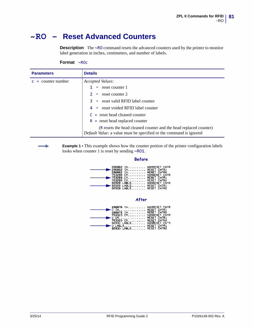
81ZPL II Commands for RFID~RO
~RO – Reset Advanced CountersDescription The ~RO command resets the advanced counters used by the printer to monitor label generation in inches, centimeters, and number of labels.
Format ~ROc
Parameters Details
c = counter number Accepted Values: 1 = reset counter 1
2 = reset counter 2
3 = reset valid RFID label counter
4 = reset voided RFID label counter
C = reset head cleaned counterR = reset head replaced counter
(R resets the head cleaned counter and the head replaced counter)Default Value: a value must be specified or the command is ignored
Example 1 • This example shows how the counter portion of the printer configuration labels looks when counter 1 is reset by sending ~RO1.
Before
After
3/25/14 RFID Programming Guide 2 P1026148-002 Rev. A
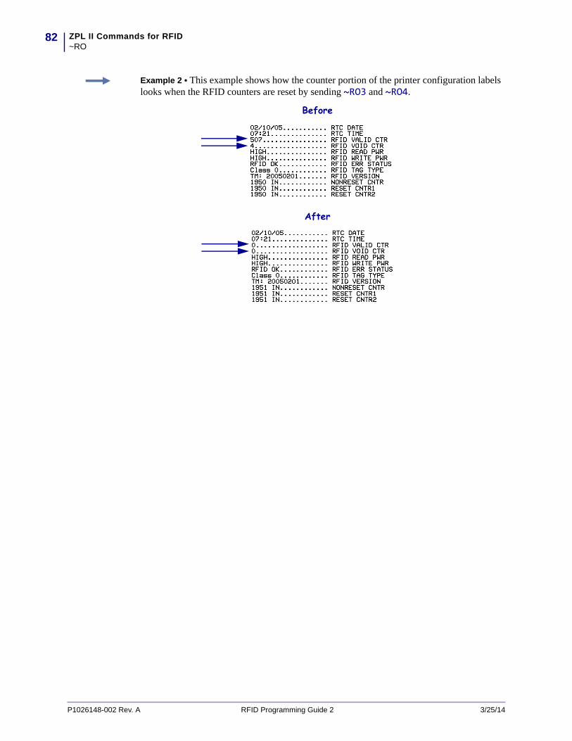
ZPL II Commands for RFID~RO
82
Example 2 • This example shows how the counter portion of the printer configuration labels looks when the RFID counters are reset by sending ~RO3 and ~RO4.
Before
After
P1026148-002 Rev. A RFID Programming Guide 2 3/25/14
83ZPL II Commands for RFID^RQ
^RQ – Quick Write EPC Data and PasswordsDescription Use this command with an Alien Higgs RFID tag and appropriate firmware to write the EPC data, access password, and kill password with one command. Doing so reduces the encoding time.
Format ^RQf,c,o[data]
Note • The access password on the tag to be written to must be 00000000 prior to sending this command.
Parameters Details
f = format Accepted Values: A = ASCII
H = Hexadecimal
E = EPC
Default Value: H
c = chip type Accepted Values: 0 (Higgs IC tag)Default Value: 0
o = option Accepted Values: 0 (write 96-bit EPC)Default Value: 0
data = the EPC data, access password, and kill password
Use the ^FD command to specify the passwords in the following format:
^FD[EPC],[access],[kill]where:
EPC = the EPC data in the format specified by the f parameter. The data should match what would be programmed with the ^RF command.
access = an optional access password in hexadecimal format. If this field is left blank, 0x00000000 is written as the access password.
kill = an optional kill password in hexadecimal format. If this field is left blank, 0x00000000 is written as the kill password.
Example 1 • This example writes the EPC data to the tag in hexadecimal format. The unspecified access and kill passwords are written as zeroes (0x00000000).
^XA^RQ^FD112233445566778899001122^XZ
Example 2 • This example writes the EPC data to the tag in hexadecimal format. The access password is written as 0xAAAAAAAA, and the kill password is written as 0xBBBBBBBB.
^XA^RQ^FD112233445566778899001122,AAAAAAAA,BBBBBBBB^XZ
Example 3 • This example writes the EPC data to the tag in EPC format. The unspecified access and kill passwords are written as zeroes (0x00000000).
^XA^RB96,30,30,30,6^RQE^FD1234.5678.9012.12^XZ
3/25/14 RFID Programming Guide 2 P1026148-002 Rev. A

ZPL II Commands for RFID^RQ
84
Example 4 • This example writes the EPC data to the tag in hexadecimal format. The access password is written as 0xAAAAAAAA, and the unspecified kill password is written as zeroes (0x00000000).
^XA^RB96,30,30,30,6^RQE^FD1234.5678.9012.12,AAAAAAAA^XZ
P1026148-002 Rev. A RFID Programming Guide 2 3/25/14

85ZPL II Commands for RFID^RR
^RR – Specify RFID Retries for a BlockDescription Use this command to change the number of times that the printer attempts to read or write to a particular block of a single RFID tag. This command is persistent and will be used in subsequent formats if not provided.
Format ^RRn,a
Note • This command’s function is different than the “number of labels” parameter in the ̂ RS command.
Parameters Details
n = number of retries Accepted Values: 0 to 10Default Value: 6
a = adaptive antenna element selection
Note • This parameter is valid only on the R110Xi4 printer with a label that is 2 in. (51 mm) or longer.
After the printer has exhausted the number of retries specified by parameter n, the printer may try other antenna elements. This parameter enables this ability. If the printer is unsuccessful communicating with the RFID tag after trying the neighboring antenna elements, the printer voids the label.
Note • Activating this parameter may slow throughput on damaged or weak RFID tags.
Accepted Values: 0 or 10 = None. The printer uses only the current antenna element selection.
1 = Neighbors. The printer attempts to read the tag using the antenna elements to the left/right and above/below the current antenna element. The antenna element that is successful is used for all subsequent RFID commands until the next unsuccessful attempt, until the printhead is opened, or until the printer is power cycled.
Default Value: 0
Example 1 • This example sets the read block retries to 5.
^XA^FN1^RR5^RFR,H^FS^HV1^FS^XZ
Example 2 • This example sets the write block retries to 2.
^XA^RR2^RFW,H^FD1234^FS^XZ
3/25/14 RFID Programming Guide 2 P1026148-002 Rev. A

ZPL II Commands for RFID^RR
86
Example 3 • On an R110Xi4 printer, this example sets the write retries to 2 and allows the printer to try neighboring antennas in the event that the current antenna cannot write to the RFID tag.
^XA^RR2,1^RFW,H^FD1234^FS^XZ
P1026148-002 Rev. A RFID Programming Guide 2 3/25/14

87ZPL II Commands for RFID^RS
^RS – Set Up RFID ParametersUse this command to set up RFID parameters including tag type, read/write position of the transponder, and error handling.
Format ^RSt,p,v,n,e,a,c,s
Use care when using this command in combination with ^RF for reading tag data. Problems can occur if the data read from the tag is going to be printed on the label. Any data read from the transponder must be positioned to be printed above the read/write position. Failure to do this will prevent read data from being printed on the label.
Parameters Details
t = tag type Gen 2 is the only tag type valid for this printer. This value cannot be changed.
p = read/write position of the transponder (programming position)
This parameter sets the read/write position of the transponder in one of two ways: absolute mode or relative mode. For more information about these modes, see Setting the Programming Position Manually on page 22.
Important • If a label format specifies a value for the programming position, this value will be used for the programming position for all labels until a new position is specified or until the transponder calibration procedure is run.
Accepted Values: Absolute Mode: xxxx = 0 to label length (in dot rows). Move the media to the specified
position xxxx on the label, measured in dot rows from the label top, before encoding. Set to 0 (no movement) if the transponder is already in the effective area without moving the media.
Relative Mode Forward: Fxxx = F0 to Fxxx (where xxx is the label length in millimeters or 999,
whichever is less). Move media forward, printing bitmap, for xxx millimeters before reading or encoding.
Relative Mode Backward: Byy = B0 to B30 (in millimeters, 30 mm maximum). Move media backward
for yy millimeters before reading or encoding. (Does not apply to the RP4T printer.)
Note • When using a backward program position, allow enough media or liner to ensure that the printer can back up the media without the leading edge disappearing under the printhead mechanism.
Default value:
F0 (which moves the leading edge of the label to the print line)
v = length of void printout
Sets the length of the void printout in vertical (Y axis) dot rows.
Accepted values: 0 to label length
Default value: label length
3/25/14 RFID Programming Guide 2 P1026148-002 Rev. A

ZPL II Commands for RFID^RS
88
n = number of labels The number of labels that will be attempted in case of read/encode failure.
Accepted values: 1 to 10
Default value: 3
e = error handling If an error persists after the specified number of labels are tried, perform this error handling action.
Accepted values:
N = No action (printer drops the label format causing the error and moves to the next queued label)
P = Place printer in Pause mode (label format stays in the queue until the user cancels)
E = Place printer in Error mode (label format stays in the queue until the user cancels)
Default value: N
Note • You can set the printer to send an error message to the host for each failure. To enable or disable this unsolicited error message, refer to the ^SX and ^SQ ZPL commands. Use V for the condition type for an RFID error.
a = signals on applicator This parameter applies only to printers that have an applicator board. For more information on applicator signals, see Timing Diagrams for RFID on page 114.
Single Signal ModeIn this mode, one start print signal starts printing. Then, at the program position (parameter p), the printer automatically stops and encodes the tag. Printing continues, and a single end print signal signifies the completion of the label.
Double Signal ModeWith RFID, when there is a non-zero program position, the label is logically split into two parts. The first part is printed, the tag encodes, and then the second part prints. If this parameter is set to “D,” then the label is split into two and requires both portions of the label to be controlled by the applicator. This means that a start print signal triggers the first portion of the label, and then when the printer reaches the RFID program position (and the motor stops), an end print signal is provided. In this mode, a second start print signal is required to print the rest of the label. When the label is complete, a final end print signal is provided.
Note • If parameter p is zero, then single signal mode is used (parameter ignored). If p is F0 (or B0) with backfeed-after, then single signal mode is used (parameter ignored).
Accepted values:
S = single signal
D = double signal
Default value: Sc = reserved Not applicable.
s = void print speed If a label is voided, the speed at which “VOID” will be printed across the label.
Accepted values: any valid print speed
Default value: the printer’s maximum print speed
Parameters Details
P1026148-002 Rev. A RFID Programming Guide 2 3/25/14

89ZPL II Commands for RFID^RS
Example 1 • The following are examples of Absolute Mode and Relative Mode for the transponder position parameter (parameter p).
Absolute Mode
1. ^RS,520 sets the encode position at 520 dots from the top edge of the label.2. ^RS,0 programs the tag without moving the media.Relative Mode
1. ^RS,F1 sets the encode position 1 mm forward from the leading edge of the label.2. ^RS,B10 sets the encode position 10 mm backwards from the leading edge of the label.3. ^RS,F0 sets the encode position at the leading edge of the label.4. ^RS,B0 sets the encode position at the leading edge of the label.
Example 2 • The following shows the difference between absolute and relative programming positions for the transponder position parameter (parameter p) with a 6-inch (152-mm, 1216-dot) label length. The end results are that the tag is programmed with the label in the same position.
print direction
encoding area
print linetear bar
1
2
1 ^RS,496, Absolute Mode, 496 dots from the top of the label
2 ^RS,F90, Relative Mode, 90 mm from the leading edge of the label
3/25/14 RFID Programming Guide 2 P1026148-002 Rev. A
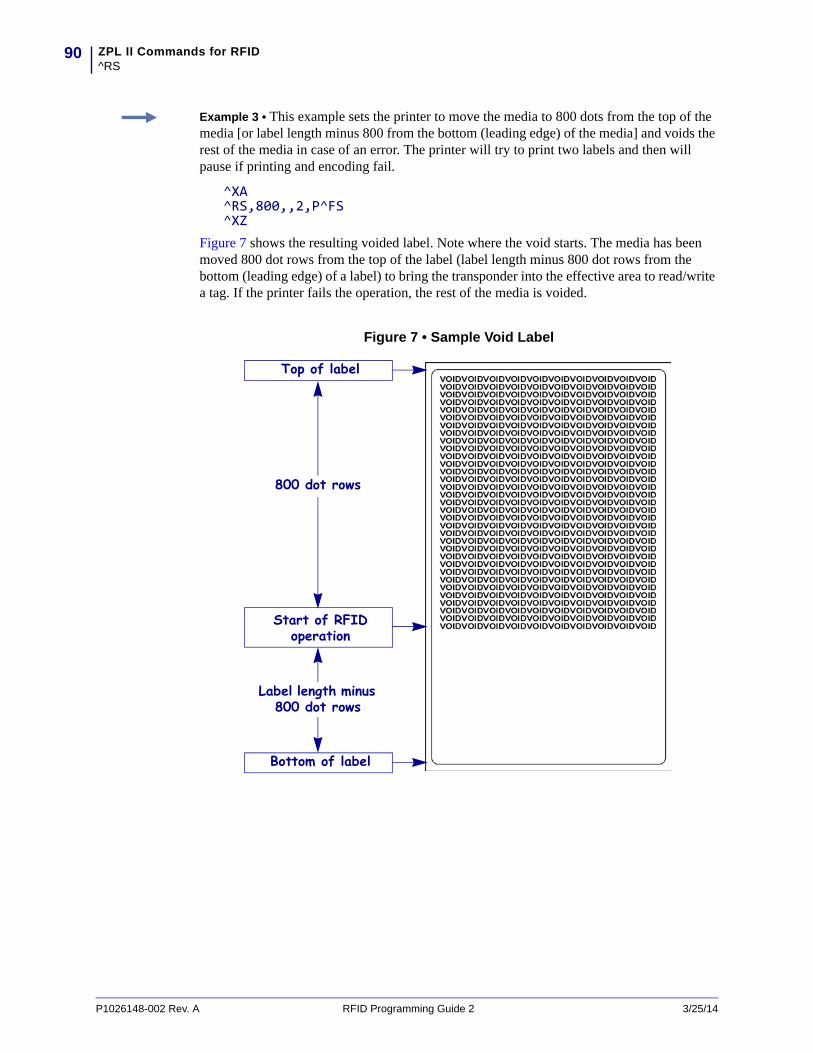
ZPL II Commands for RFID^RS
90
Example 3 • This example sets the printer to move the media to 800 dots from the top of the media [or label length minus 800 from the bottom (leading edge) of the media] and voids the rest of the media in case of an error. The printer will try to print two labels and then will pause if printing and encoding fail.
^XA^RS,800,,2,P^FS^XZ
Figure 7 shows the resulting voided label. Note where the void starts. The media has been moved 800 dot rows from the top of the label (label length minus 800 dot rows from the bottom (leading edge) of a label) to bring the transponder into the effective area to read/write a tag. If the printer fails the operation, the rest of the media is voided.
Figure 7 • Sample Void Label
Top of label
Start of RFID operation
800 dot rows
Bottom of label
Label length minus 800 dot rows
P1026148-002 Rev. A RFID Programming Guide 2 3/25/14

91ZPL II Commands for RFID^RS
Example 4 • This example sets the printer to move the media to 800 dots from the top of the media [or label length - 500 from the bottom (leading edge) of the media] and prints “VOID” 500 dots in vertical length (Y axis) in case of an error.
^XA^RS,800,500,2,P^FS^XZ
Figure 8 shows the resulting voided label. Note where the void starts. The media has been moved 800 dot rows from the top of the label [label length minus 800 dot rows from the bottom (leading edge) of a label] to bring the transponder into the effective area to read/write a tag. If the printer fails the operation, an area that is 500 dot rows of the media is voided instead of the entire rest of the media.
Figure 8 • Sample Void Label, 500 Dot Row Area Voided
Top of label
Start of RFID operation
800 dot rows
Bottom of label
Label length minus 800 dot rows
500 dot rows
3/25/14 RFID Programming Guide 2 P1026148-002 Rev. A
ZPL II Commands for RFID^RU
92
^RU – Read Unique RFID Chip SerializationDescription Use this command to read the TID (Tag ID) data from the current chip and format a unique 38-bit serial number, which will be placed in the lower (least significant) 38 bits of the EPC code.
Format ^RUa,b
Important • Please note the following:
• This command is invalid on the RP4T printer. • Supported printers must use firmware version V53.17.20 or later, and the reader firmware
must be version 20120123 or later.
Parameters Details
a = prefix Specifies the prefix in ASCII Binary
Accepted Values: Only ASCII characters 1 and 0 are accepted. Maximum of 38 characters.The number of bits in the value specifies the length of the prefix. The prefix is placed as the left-most (most significant) bits in the unique serial number.
If nothing is specified, the default value will be used.
Default Value: The MCS prefix is determined by the MDID in the TID of the chip read:• 100 = EM Micro• Impinj = 101• Alien = 110• NXP = 111
b = special character Special character for serial number inclusion.
Accepted Values: Any ASCII character other than the current Command character, Control character, Delimiter character, or any of the Real-Time Clock (RTC) characters.Default Value: #
P1026148-002 Rev. A RFID Programming Guide 2 3/25/14
93ZPL II Commands for RFID^RU
Note • Serial number inclusion:
One of several data elements can be included into any ^FD data string in the same way that Real Time Clock data is included. Use any of the commands below to include a data pattern based on the serial number. These are defined using the default value for the Special Character.
#S = include 38-bit serial number derived from TID in decimal form.
#H = include 38-bit serial number derived from TID in hexadecimal form.
#E = include the entire 96-bit EPC code, including the 38-bit serial number derived from TID in decimal form.
#F = include the entire 96-bit EPC code, including the 38-bit serial number derived from TID in hexadecimal form.
#P = include the entire 96-bit EPC code, but use the tag’s preprogrammed, 38-bit SGTIN serial number in decimal form.*
#Q = include the entire 96-bit EPC code, but use the tag’s preprogrammed, 38-bit SGTIN serial number in hexadecimal form.*
* If the EPC has been preprogrammed (typically by the manufacturer) with the chip-based RFID serialization scheme, then the serialized data does not have to be written back to the EPC memory, which saves time. #P and #Q simply format the data that is read from the EPC memory bank.
Example 1 • Read the TID from the tag, create a serial number based on the tag type, write 12<serial number (5 bytes)>000000000000 to the 96-bit EPC field, and print the serial number (in hex format) on the label.
^XA^RU^FO10,10^A0N,50,50^FDSerial Number: #H^FS^RFW,H^FD12#H^FS^XZ
Example 2 • Read the TID from the tag, create a serial number based on the tag type, write the serial number to the EPC field (lower 38 bits) while maintaining the contents of the rest of the EPC memory, print Serial Number: <serial number in hex format> on the label, and return Serial Number: <serial number in hex format> to the host. Perform this operation on three label formats.
^XA^RU^FO10,10^A0N,50,50^FN1^FS^FN1^FDSerial Number: #H^FS^FH^HV1,24, ,_0D_0A,L^FS^RFW,H^FD#F^FS^PQ3^XZ
3/25/14 RFID Programming Guide 2 P1026148-002 Rev. A

ZPL II Commands for RFID^RU
94
Example 3 • Read the full EPC (already serialized) from the tag, print Serial Number: <full EPC in decimal format> on the label, and return Serial Number: <full EPC in decimal format> to the host.
^XA^RU^FO10,10^A0N,50,50^FN1^FS^FN1^FDSerial Number: #P^FS^FH^HV1,44, ,_0D_0A,L^FS^XZ
P1026148-002 Rev. A RFID Programming Guide 2 3/25/14
95ZPL II Commands for RFID~RV
3/25/14 RFID Programming Guide 2 P1026148-002 Rev. A
~RV – Report RFID Encoding ResultsDescription Use this command to tell the printer to send RFID encoding success or failure results to the host computer after each label format completes.
Format ~RVa
Parameters Details
a = enable/disable Enables or disables the results reporting feature.
Accepted Values: E = EnableD = Disable
Default Value: D
Example 1 • Assume that the following code is sent and that there is no RFID tag in the field.
~RVE^XA^RS8,0,,3^RMY^RFR,H^XZ
The printer attempts to program a tag three times and then returns the following to the host:
_-,3_The minus sign indicates that the programming attempt failed entirely and voided three labels.
Example 2 • Assume that the same code is sent and that the first two attempts at programming a tag are unsuccessful. The third attempt succeeds.
~RVE^XA^RS8,0,,3^RMY^RFR,H^XZ
The printer attempts to program a tag three times and then returns the following to the host:
_+,2_The plus sign indicates that the programming attempt was successful and voided two labels.
ZPL II Commands for RFID^RW
96
^RW – Set RF Power Levels for Read and WriteDescription Use this command to set the RFID read and write power levels. This function is useful when using different tag types or transponders that require different power levels to obtain the best read and write abilities. If not enough power is applied, the transponder may not have sufficient power for programming, and tag data will fail to encode. If too much power is applied, the extra power may cause data communication errors.
Format ^RWr,w,a
Note • The R110Xi4 printer automatically selects the best antenna element and read/write power levels for the media during RFID transponder calibration. It may also set the levels during an adaptive antenna sweep. Use the ~HL command (see ^HL or ~HL on page 61) to view the antenna element and power settings being used.
Parameters Details
r = read power This parameter sets the power level to match the desired output as calibrated in the factory.
Values: 0 to 30Default Value: 16
w = write power This parameter sets the power level to match the desired output as calibrated in the factory.
Values: 0 to 30Default Value: 16
P1026148-002 Rev. A RFID Programming Guide 2 3/25/14
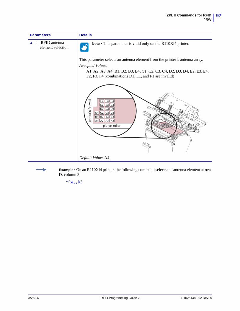
97ZPL II Commands for RFID^RW
a = RFID antenna element selection
Note • This parameter is valid only on the R110Xi4 printer.
This parameter selects an antenna element from the printer’s antenna array.
Accepted Values: A1, A2, A3, A4, B1, B2, B3, B4, C1, C2, C3, C4, D2, D3, D4, E2, E3, E4, F2, F3, F4 (combinations D1, E1, and F1 are invalid)
Default Value: A4
Parameters Details
Example • On an R110Xi4 printer, the following command selects the antenna element at row D, column 3:
^RW,,D3
3/25/14 RFID Programming Guide 2 P1026148-002 Rev. A
ZPL II Commands for RFID^RZ
98
^RZ – Set RFID Tag Password and Lock Tag
Description Use this command to define a password for a tag during writing.
With Gen 2 tags, you can lock a tag’s memory bank with an access password or define a kill password that can be used to permanently disable the tag. If you do not set access or kill passwords for a tag, the tag ignores any read or write commands that try to use these functions.
Format ^RZp,m,l
Important • ^RZ must not be used in conjunction with ^RL on page 77. Be consistent with use of one locking method or the other.
Note • The printer can set a kill password, but the printer cannot kill a tag.
Parameters Details
p = password This parameter sets a password for the RFID tag.
Gen 2 tags use a 32-bit password and specify the memory bank and lock style. The password must be 8 hexadecimal characters long. Use ^RF on page 73 to read the passwords.
Accepted Values: 00000000 to FFFFFFFF (hexadecimal)Default Value: none
m = memory bank This parameter specifies the type of RFID tag password.
Accepted Values: K = kill password
A = access password
E = EPC
T = tag identifier (TID)
U = user
Default Value: none
l = lock style This parameter specifies the RFID tag password status.
Accepted Values:
U = unlocked
L = locked
O = permanently unlocked (open)
P = permanently locked (protected)
W = write value (used only for the kill password memory bank)
Default Value: none
P1026148-002 Rev. A RFID Programming Guide 2 3/25/14
99ZPL II Commands for RFID^RZ
Example 1 • This example encodes EPC data 112233445566778899001122 to the tag in Hex format, write protects the tag’s EPC data with password 1234ABCD, and leaves the tag’s access password unlocked.
^XA^RFW,H^FD112233445566778899001122^FS^RZ1234ABCD,E,L^FS^XZ
Example 2 • This example encodes EPC data 112233445566778899001122 to the tag in Hex format, write protects the tag’s EPC data with password 1234ABCD, and makes the tag’s access password unreadable.
^XA^RFW,H^FD112233445566778899001122^FS^RZ1234ABCD,E,L^FS^RZ1234ABCD,A,L^FS^XZ
The following code unprotects EPC data 112233445566778899001122 using the password 1234ABCD, encodes EPC data newdata to the tag in ASCII format, and then write protects the tag’s new EPC data. The access password and its lock state are not changed, so the access password remains unreadable.
^XA^RZ1234ABCD,E,U^FS^RFW,A^FDnewdata^FS^RZ1234ABCD,E,L^FS^xz
Example 3 • This example unlocks the locked access password from the previous example.
^XA^RZ1234ABCD,A,U^FS^XZ
3/25/14 RFID Programming Guide 2 P1026148-002 Rev. A

ZPL II Commands for RFID^RZ
100
Notes • ____________________________________________________________________
__________________________________________________________________________
__________________________________________________________________________
__________________________________________________________________________
__________________________________________________________________________
__________________________________________________________________________
__________________________________________________________________________
__________________________________________________________________________
__________________________________________________________________________
__________________________________________________________________________
P1026148-002 Rev. A RFID Programming Guide 2 3/25/14
8SGD Commands for RFID
This section contains the Set/Get/Do (SGD) commands for RFID-specific applications.
For non-RFID SGD commands, refer to the Programming Guide for ZPL, ZBI, Set-Get-Do, Mirror, and WML. A copy of the manual is located on the User CD that came with your printer, or you can download a copy from http://www.zebra.com/manuals.
3/25/14 RFID Programming Guide 2 P1026148-002 Rev. A
Contentsodometer.rfid.valid_resettable . . . . . . . . . . . . . . . . . . . . . . . . . . . . . . . . . . . . . . . . . . . . 102odometer.rfid.void_resettable. . . . . . . . . . . . . . . . . . . . . . . . . . . . . . . . . . . . . . . . . . . . . 103rfid.error.response . . . . . . . . . . . . . . . . . . . . . . . . . . . . . . . . . . . . . . . . . . . . . . . . . . . . . 104rfid.position.program . . . . . . . . . . . . . . . . . . . . . . . . . . . . . . . . . . . . . . . . . . . . . . . . . . . 105rfid.reader_1.antenna_port. . . . . . . . . . . . . . . . . . . . . . . . . . . . . . . . . . . . . . . . . . . . . . . 106rfid.reader_1.power.read . . . . . . . . . . . . . . . . . . . . . . . . . . . . . . . . . . . . . . . . . . . . . . . . 107rfid.reader_1.power.write . . . . . . . . . . . . . . . . . . . . . . . . . . . . . . . . . . . . . . . . . . . . . . . . 108rfid.tag.calibrate . . . . . . . . . . . . . . . . . . . . . . . . . . . . . . . . . . . . . . . . . . . . . . . . . . . . . . . 109rfid.tag.data . . . . . . . . . . . . . . . . . . . . . . . . . . . . . . . . . . . . . . . . . . . . . . . . . . . . . . . . . . 110rfid.tag.test . . . . . . . . . . . . . . . . . . . . . . . . . . . . . . . . . . . . . . . . . . . . . . . . . . . . . . . . . . . .111
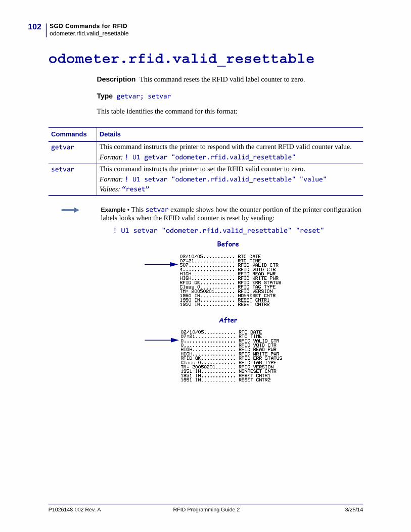
SGD Commands for RFIDodometer.rfid.valid_resettable
102
P1026148-002 Rev. A RFID Programming Guide 2 3/25/14
odometer.rfid.valid_resettableDescription This command resets the RFID valid label counter to zero.
Type getvar; setvar
This table identifies the command for this format:
Commands Details
getvar This command instructs the printer to respond with the current RFID valid counter value.
Format: ! U1 getvar "odometer.rfid.valid_resettable"
setvar This command instructs the printer to set the RFID valid counter to zero.
Format: ! U1 setvar "odometer.rfid.valid_resettable" "value" Values: “reset”
Example • This setvar example shows how the counter portion of the printer configuration labels looks when the RFID valid counter is reset by sending:
! U1 setvar "odometer.rfid.valid_resettable" "reset"
Before
After
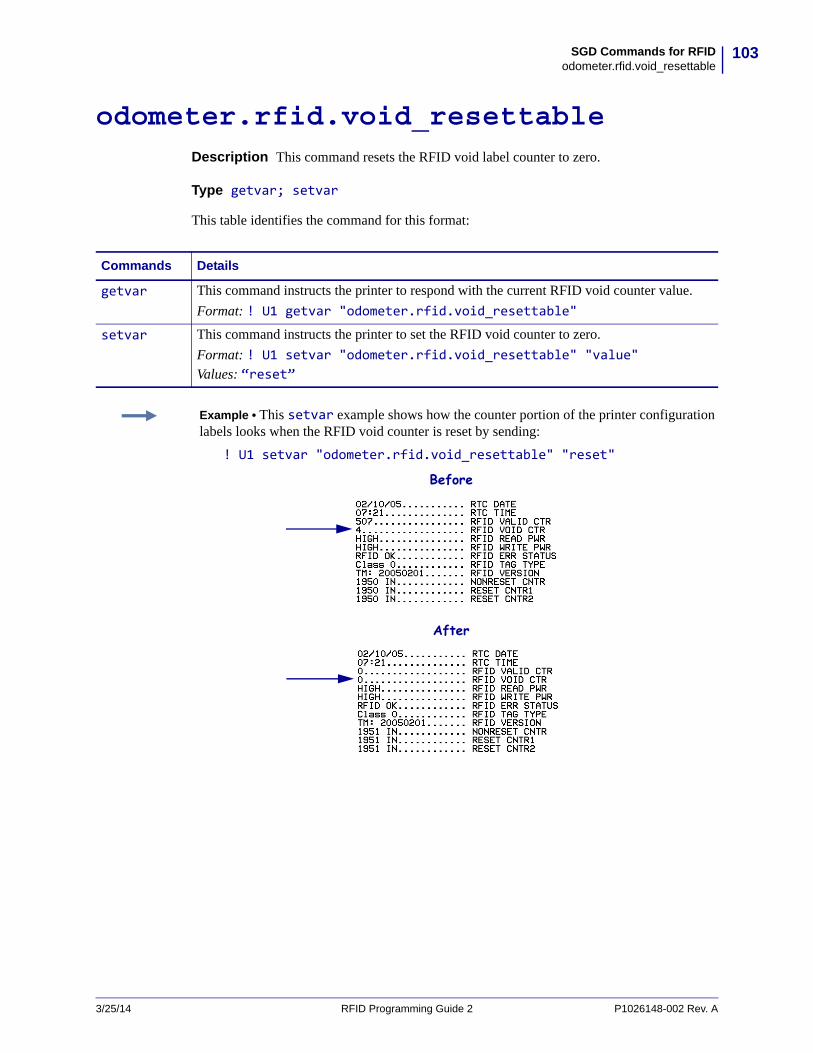
103SGD Commands for RFIDodometer.rfid.void_resettable
3/25/14 RFID Programming Guide 2 P1026148-002 Rev. A
odometer.rfid.void_resettableDescription This command resets the RFID void label counter to zero.
Type getvar; setvar
This table identifies the command for this format:
Commands Details
getvar This command instructs the printer to respond with the current RFID void counter value.
Format: ! U1 getvar "odometer.rfid.void_resettable"
setvar This command instructs the printer to set the RFID void counter to zero.
Format: ! U1 setvar "odometer.rfid.void_resettable" "value" Values: “reset”
Example • This setvar example shows how the counter portion of the printer configuration labels looks when the RFID void counter is reset by sending:
! U1 setvar "odometer.rfid.void_resettable" "reset"
Before
After
SGD Commands for RFIDrfid.error.response
104
P1026148-002 Rev. A RFID Programming Guide 2 3/25/14
rfid.error.responseDescription During an error condition, an error message shows on the second line of the display. This command can be used to retrieve that error message. See Table 5 on page 49 in the RFID Troubleshooting section for descriptions of the error messages.
Type getvar
\This table identifies the command for this format:
Commands Details
getvar This command instructs the printer to respond with any active RFID error messages.
Format: ! U1 getvar "rfid.error.response"
Example • This getvar example shows responses that you may get in different situations:
! U1 getvar "rfid.error.response"
If no RFID tag is present, you get the following response:
NO TAG FOUND
If an RFID tag is present and there are no errors, you get the following response:
RFID OK

105SGD Commands for RFIDrfid.position.program
3/25/14 RFID Programming Guide 2 P1026148-002 Rev. A
rfid.position.programDescription This command sets the read/write position of the transponder (programming position) in one of two ways: absolute mode or relative mode. For more information about these modes, see Using the Correct Programming Position on page 21.
Type getvar; setvar
This table identifies the command for this format:
Important • If this command is used to specify a value for the programming position, this value will be used for the programming position for all labels until a new position is specified or until the transponder calibration procedure is run.
Commands Details
getvar This command instructs the printer to respond with the current programming position.
Format: ! U1 getvar "rfid.position.program"
setvar This command instructs the printer to set the programming position.
Format: ! U1 setvar "rfid.position.program" "value" Values:
Absolute Mode: "xxxx" = 0 to label length (in dot rows). Move the media to the specified position xxxx
on the label, measured in dot rows from the label top, before encoding. Set to 0 (no movement) if the transponder is already in the effective area without moving the media.
Relative Mode Forward: "Fxxx" = F0 to Fxxx (where xxx is the label length in millimeters or 999, whichever is
less). Move media forward, printing bitmap, for xxx millimeters before reading or encoding.
Relative Mode Backward: "Byy" = B0 to B30 (in millimeters, 30 mm maximum). Move media backward for yy
millimeters before reading or encoding. (Does not apply to the RP4T printer.)
Note • When using a backward program position, allow enough media or liner to ensure that the printer can back up the media without the leading edge disappearing under the printhead mechanism.
Accepted Values: Default value:
F0 (which moves the leading edge of the label to the print line)
Example • This setvar example shows the programming position being set at 15 mm from the leading edge of the label.
! U1 setvar "rfid.position.program" "F15"
When the setvar value is set to "15", the getvar result is "F15".
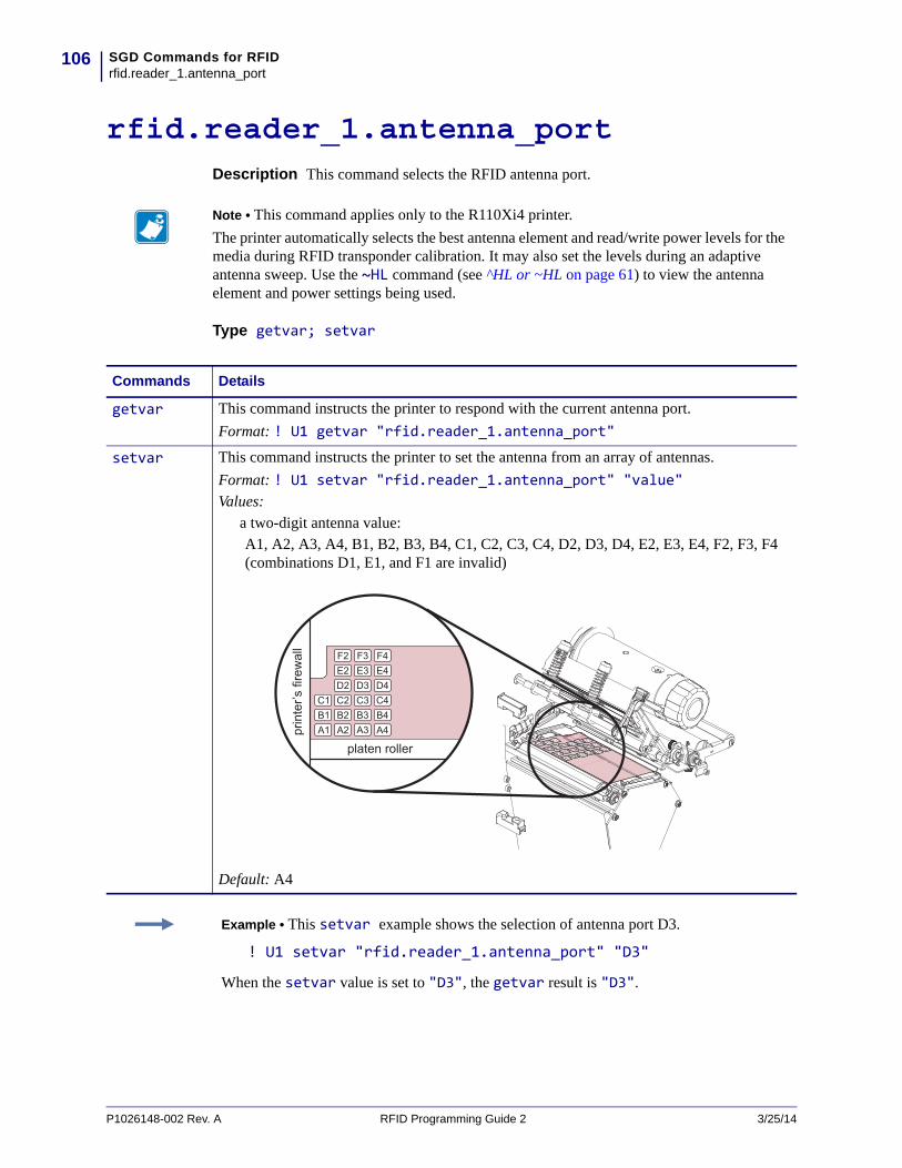
SGD Commands for RFIDrfid.reader_1.antenna_port
106
P1026148-002 Rev. A RFID Programming Guide 2 3/25/14
rfid.reader_1.antenna_portDescription This command selects the RFID antenna port.
Type getvar; setvar
Note • This command applies only to the R110Xi4 printer.
The printer automatically selects the best antenna element and read/write power levels for the media during RFID transponder calibration. It may also set the levels during an adaptive antenna sweep. Use the ~HL command (see ^HL or ~HL on page 61) to view the antenna element and power settings being used.
Commands Details
getvar This command instructs the printer to respond with the current antenna port.
Format: ! U1 getvar "rfid.reader_1.antenna_port"
setvar This command instructs the printer to set the antenna from an array of antennas.
Format: ! U1 setvar "rfid.reader_1.antenna_port" "value" Values:
a two-digit antenna value:A1, A2, A3, A4, B1, B2, B3, B4, C1, C2, C3, C4, D2, D3, D4, E2, E3, E4, F2, F3, F4 (combinations D1, E1, and F1 are invalid)
Default: A4
Example • This setvar example shows the selection of antenna port D3.
! U1 setvar "rfid.reader_1.antenna_port" "D3"
When the setvar value is set to "D3", the getvar result is "D3".
107SGD Commands for RFIDrfid.reader_1.power.read
3/25/14 RFID Programming Guide 2 P1026148-002 Rev. A
rfid.reader_1.power.readDescription This command sets the RFID reader power level for reading RFID tags.
Type getvar; setvar
Note • The R110Xi4 printer automatically selects the best antenna element and read/write power levels for the media during RFID transponder calibration. It may also set the levels during an adaptive antenna sweep. Use the ~HL command (see ^HL or ~HL on page 61) to view the antenna element and power settings being used.
Commands Details
getvar This command instructs the printer to respond with the antenna’s current read power level.
Format: ! U1 getvar "rfid.reader_1.power.read"
setvar This command instructs the printer to set the antenna’s read power level.
Format: ! U1 setvar "rfid.reader_1.power.read" "value" R53.16.3Z:Values: 0 to 30Default Value: 16RP4T (all firmware versions), R53.16.4Z, V53.17.7, and later:Values: 0 to 30, up, down (up and down change the current value by 1)Default Value: 16
Example • This setvar example sets the antenna to high power for reading RFID tags.
! U1 setvar "rfid.reader_1.power.read" "16"
When the setvar value is set to "16", the getvar result is "16".

SGD Commands for RFIDrfid.reader_1.power.write
108
P1026148-002 Rev. A RFID Programming Guide 2 3/25/14
rfid.reader_1.power.writeDescription This command sets the RFID reader power level for writing to RFID tags.
Type getvar; setvar
This table identifies the command for this format:
Note • The R110Xi4 printer automatically selects the best antenna element and read/write power levels for the media during RFID transponder calibration. It may also set the levels during an adaptive antenna sweep. Use the ~HL command (see ^HL or ~HL on page 61) to view the antenna element and power settings being used.
Commands Details
getvar This command instructs the printer to respond with the antenna’s current write power level.
Format: ! U1 getvar "rfid.reader_1.power.write"
setvar This command instructs the printer to set the write power level on the RFID reader.
Format: ! U1 setvar "rfid.reader_1.power.write" "value" R53.16.3Z:Values: 0 to 30Default Value: 16RP4T (all firmware versions), R53.16.4Z, V53.17.7, and later:Values: 0 to 30, up, down (up and down change the current value by 1)Default Value: 16
Example • This setvar example sets the antenna to high power for writing to RFID tags.
! U1 setvar "rfid.reader_1.power.write" "16"
When the setvar value is set to "16", the getvar result is "16".
109SGD Commands for RFIDrfid.tag.calibrate
3/25/14 RFID Programming Guide 2 P1026148-002 Rev. A
rfid.tag.calibrateDescription This command sets the RFID programming position through a tag calibration, or it restores the programming position back to the printer default. For the R110Xi4 printer, this option also selects the best antenna element and read/write power levels for the media.
Type setvar
This table identifies the command for this format:
Important • Before using this command, see Using the Correct Programming Position on page 21. Running this command may not be the best option for your printer.
Commands Details
setvar This command instructs the printer to set the programming position.
Format: ! U1 setvar "rfid.tag.calibrate" "value" Values:
restore run
Example 1 • This setvar example restores the programming position back to the printer’s default value.
! U1 setvar "rfid.tag.calibrate" "restore"
Example 2 • This setvar example performs RFID tag calibration.
To use this command, load the printer with RFID media, and close the printhead. For the R110Xi4 printer, remove all transponders from the first 1.25 in. (32 mm) of media. Allow this portion of the media to extend out the front of the printer to allow for backfeed during the transponder calibration procedure.
! U1 setvar "rfid.tag.calibrate" "run"

SGD Commands for RFIDrfid.tag.data
110
P1026148-002 Rev. A RFID Programming Guide 2 3/25/14
rfid.tag.dataDescription This command tells the RFID reader to attempt to read a tag over the RFID antenna, even if the printhead is open. Results are returned to the host.
Before running this command, position an RFID label over the printer’s RFID antenna. To locate the RFID antenna on your printer, see RFID Antenna Location on page 41.
Type getvar
This table identifies the command for this format:
Commands Details
getvar This command instructs the printer to respond with the current tag’s data.
Format: ! U1 getvar "rfid.tag.data"
Example 1 • This getvar example gets the current tag’s data, assuming that an RFID label with data “0123456789ABCDEF12345678” is in place over the antenna.
! U1 setvar "rfid.tag.data"The printer responds with 0123456789ABCDEF12345678.
Example 2 • This getvar example gets the current tag’s data, assuming that no tag data can be read or that no tag is present.
! U1 setvar "rfid.tag.data"The printer responds with NO DATA.
111SGD Commands for RFIDrfid.tag.test
rfid.tag.testDescription This command performs an RFID test. In the RFID test, the printer attempts to read and write to a transponder that you place over the RFID antenna. Results are displayed on the printer’s control panel display. To locate the RFID antenna on your printer, see RFID Antenna Location on page 41.
In the slow version of the RFID test, the printer first displays the hardware version, the reader firmware version, and the program position.
Type setvar
This table identifies the command for this format:
Note • This command is valid only on RP4T printers.
Commands Details
setvar This command instructs the printer to set the programming position.
Format: ! U1 setvar "rfid.tag.test" "value" Values:
quick slow
Example 1 • This setvar example performs a quick RFID test, which shows a pass or fail message.
! U1 setvar "rfid.tag.test" "quick"
Example 2 • This setvar example performs a slow RFID test, which shows the success or failure of each read or write tag operation.
! U1 setvar "rfid.tag.test" "slow"
3/25/14 RFID Programming Guide 2 P1026148-002 Rev. A
SGD Commands for RFIDrfid.tag.test
112
Notes • ____________________________________________________________________
__________________________________________________________________________
__________________________________________________________________________
__________________________________________________________________________
__________________________________________________________________________
__________________________________________________________________________
__________________________________________________________________________
__________________________________________________________________________
__________________________________________________________________________
__________________________________________________________________________
P1026148-002 Rev. A RFID Programming Guide 2 3/25/14
9RFID Applicator Signals
This section applies to printers that have applicator ports and that are being used in a print-and-apply system. Included are timing diagrams for good and bad RFID tags and the pin configuration for the applicator port. For basic timing diagrams, see the User Guide for your printer.
3/25/14 RFID Programming Guide 2 P1026148-002 Rev. A
ContentsTiming Diagrams for RFID . . . . . . . . . . . . . . . . . . . . . . . . . . . . . . . . . . . . . . . . . . . . . . . 114
Single Signal Mode . . . . . . . . . . . . . . . . . . . . . . . . . . . . . . . . . . . . . . . . . . . . . . . . . . 114Double Signal Mode. . . . . . . . . . . . . . . . . . . . . . . . . . . . . . . . . . . . . . . . . . . . . . . . . . 116
Applicator Interface Connector Pin Configuration . . . . . . . . . . . . . . . . . . . . . . . . . . . . . 117Jumper Configurations and Pinouts for +5 V I/O Operation. . . . . . . . . . . . . . . . . . . . 120Pinouts for +24-28 V I/O Operation . . . . . . . . . . . . . . . . . . . . . . . . . . . . . . . . . . . . . . 121
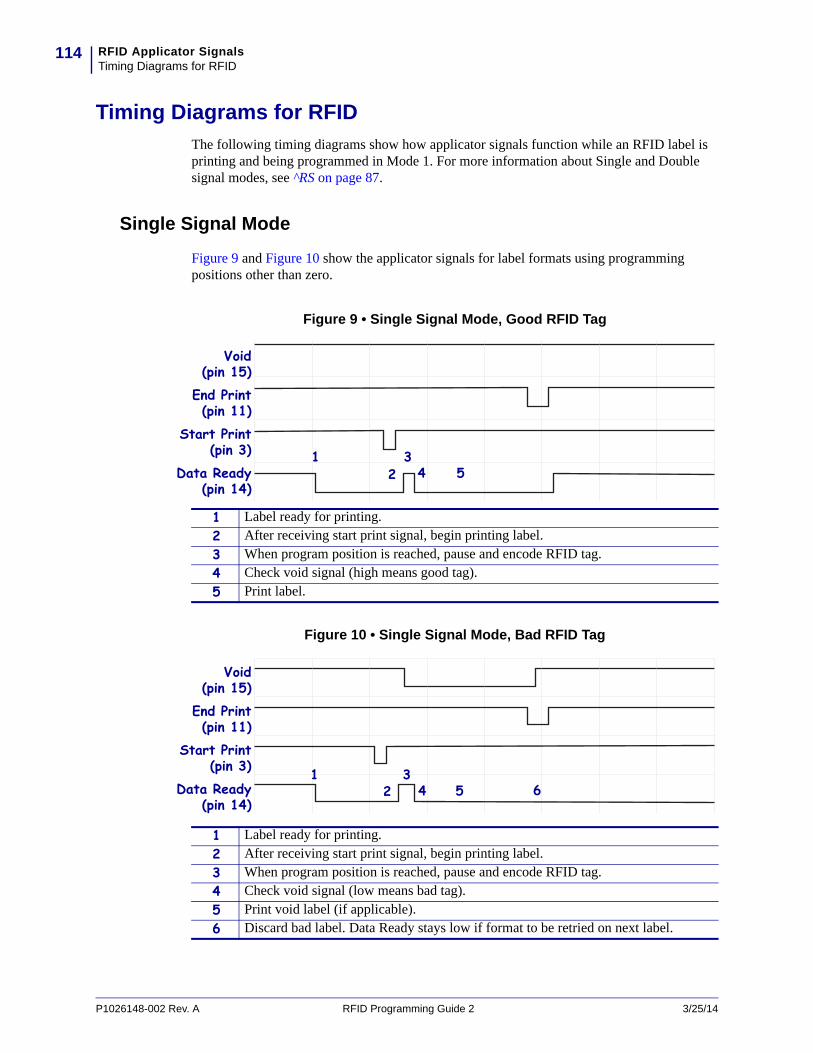
RFID Applicator SignalsTiming Diagrams for RFID
114
Timing Diagrams for RFID
The following timing diagrams show how applicator signals function while an RFID label is printing and being programmed in Mode 1. For more information about Single and Double signal modes, see ^RS on page 87.
Single Signal Mode
Figure 9 and Figure 10 show the applicator signals for label formats using programming positions other than zero.
Figure 9 • Single Signal Mode, Good RFID Tag
Figure 10 • Single Signal Mode, Bad RFID Tag
Start Print(pin 3)
Data Ready(pin 14)
End Print(pin 11)
Void(pin 15)
1 34 52
1 Label ready for printing.
2 After receiving start print signal, begin printing label.
3 When program position is reached, pause and encode RFID tag.
4 Check void signal (high means good tag).
5 Print label.
Start Print(pin 3)
Data Ready(pin 14)
End Print(pin 11)
Void(pin 15)
1 34 5 62
1 Label ready for printing.
2 After receiving start print signal, begin printing label.
3 When program position is reached, pause and encode RFID tag.
4 Check void signal (low means bad tag).
5 Print void label (if applicable).
6 Discard bad label. Data Ready stays low if format to be retried on next label.
P1026148-002 Rev. A RFID Programming Guide 2 3/25/14

115RFID Applicator SignalsTiming Diagrams for RFID
Figure 11 and Figure 12 show the applicator signals for label formats using zero for their programming position.
Figure 11 • Single Signal Mode, Good RFID Tag
Figure 12 • Single Signal Mode, Bad RFID Tag
Start Print(pin 3)
Data Ready(pin 14)
End Print(pin 11)
Void(pin 15)
213
1 Encode RFID tag.
2 Check void signal (high means good tag). Label ready for printing.
3 After receiving start print signal, print label.
Start Print(pin 3)
Data Ready(pin 14)
End Print(pin 11)
Void(pin 15)
421
3
1 Encode RFID tag.
2 Check void signal (low means bad tag).
3 After receiving start print signal, print void label (if applicable).
4 Discard bad label. Data Ready stays low if format to be retried on next label.
3/25/14 RFID Programming Guide 2 P1026148-002 Rev. A

RFID Applicator SignalsTiming Diagrams for RFID
116
Double Signal Mode
Figure 13 and Figure 14 show the applicator signals for good and bad tags using double signal mode.
Figure 13 • Double Signal Mode, Good RFID Tag
Figure 14 • Double Signal Mode, Bad RFID Tag
Start Print(pin 3)
Data Ready(pin 14)
End Print(pin 11)
Void(pin 15)
12
34 5 6
1 Label ready for printing.
2 After receiving start print signal, print first part of label.
3 When program position is reached, stop and encode RFID tag.
4 Check void signal (high means good tag).
5 Wait for second start signal.
6 Print second part of label.
Start Print(pin 3)
Data Ready(pin 14)
End Print(pin 11)
Void(pin 15)
12
34 5 7
6
1 Label ready for printing.
2 After receiving start print signal, print first part of label.
3 When program position is reached, stop and encode RFID tag.
4 Check void signal (low means bad tag).
5 Wait for second start signal.
6 Void remainder of label (if applicable).
7 Discard bad label. Data Ready stays low if format to be retried on next label.
P1026148-002 Rev. A RFID Programming Guide 2 3/25/14
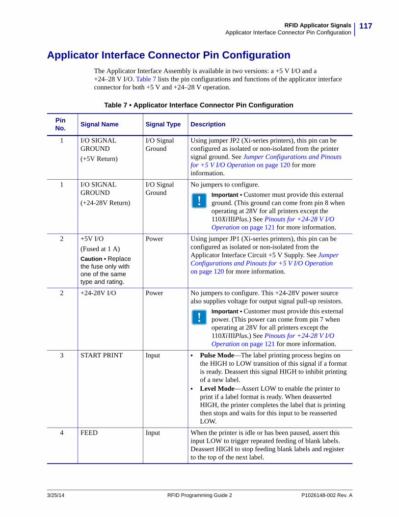
117RFID Applicator SignalsApplicator Interface Connector Pin Configuration
Applicator Interface Connector Pin Configuration
The Applicator Interface Assembly is available in two versions: a +5 V I/O and a +24–28 V I/O. Table 7 lists the pin configurations and functions of the applicator interface connector for both +5 V and +24–28 V operation.
Table 7 • Applicator Interface Connector Pin Configuration
Pin No.
Signal Name Signal Type Description
1 I/O SIGNAL GROUND
(+5V Return)
I/O Signal Ground
Using jumper JP2 (Xi-series printers), this pin can be configured as isolated or non-isolated from the printer signal ground. See Jumper Configurations and Pinouts for +5 V I/O Operation on page 120 for more information.
1 I/O SIGNAL GROUND
(+24-28V Return)
I/O Signal Ground
No jumpers to configure.
Important • Customer must provide this external ground. (This ground can come from pin 8 when operating at 28V for all printers except the 110XiIIIPlus.) See Pinouts for +24-28 V I/O Operation on page 121 for more information.
2 +5V I/O
(Fused at 1 A)
Caution • Replace the fuse only with one of the same type and rating.
Power Using jumper JP1 (Xi-series printers), this pin can be configured as isolated or non-isolated from the Applicator Interface Circuit +5 V Supply. See Jumper Configurations and Pinouts for +5 V I/O Operation on page 120 for more information.
2 +24-28V I/O Power No jumpers to configure. This +24-28V power source also supplies voltage for output signal pull-up resistors.
Important • Customer must provide this external power. (This power can come from pin 7 when operating at 28V for all printers except the 110XiIIIPlus.) See Pinouts for +24-28 V I/O Operation on page 121 for more information.
3 START PRINT Input • Pulse Mode—The label printing process begins on the HIGH to LOW transition of this signal if a format is ready. Deassert this signal HIGH to inhibit printing of a new label.
• Level Mode—Assert LOW to enable the printer to print if a label format is ready. When deasserted HIGH, the printer completes the label that is printing then stops and waits for this input to be reasserted LOW.
4 FEED Input When the printer is idle or has been paused, assert this input LOW to trigger repeated feeding of blank labels. Deassert HIGH to stop feeding blank labels and register to the top of the next label.
3/25/14 RFID Programming Guide 2 P1026148-002 Rev. A
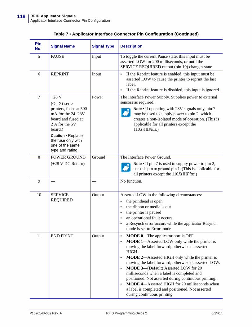
RFID Applicator SignalsApplicator Interface Connector Pin Configuration
118
5 PAUSE Input To toggle the current Pause state, this input must be asserted LOW for 200 milliseconds, or until the SERVICE REQUIRED output (pin 10) changes state.
6 REPRINT Input • If the Reprint feature is enabled, this input must be asserted LOW to cause the printer to reprint the last label.
• If the Reprint feature is disabled, this input is ignored.
7 +28 V
(On Xi-series printers, fused at 500 mA for the 24–28V board and fused at 2 A for the 5V board.)
Caution • Replace the fuse only with one of the same type and rating.
Power The Interface Power Supply. Supplies power to external sensors as required.
Note • If operating with 28V signals only, pin 7 may be used to supply power to pin 2, which creates a non-isolated mode of operation. (This is applicable for all printers except the 110XiIIIPlus.)
8 POWER GROUND
(+28 V DC Return)
Ground The Interface Power Ground.
Note • If pin 7 is used to supply power to pin 2, use this pin to ground pin 1. (This is applicable for all printers except the 110XiIIIPlus.)
9 — — No function.
10 SERVICE REQUIRED
Output Asserted LOW in the following circumstances:
• the printhead is open• the ribbon or media is out• the printer is paused • an operational fault occurs• a Resynch error occurs while the applicator Resynch
mode is set to Error mode
11 END PRINT Output • MODE 0—The applicator port is OFF.• MODE 1—Asserted LOW only while the printer is
moving the label forward; otherwise deasserted HIGH.
• MODE 2—Asserted HIGH only while the printer is moving the label forward; otherwise deasserted LOW.
• MODE 3—(Default) Asserted LOW for 20 milliseconds when a label is completed and positioned. Not asserted during continuous printing.
• MODE 4—Asserted HIGH for 20 milliseconds when a label is completed and positioned. Not asserted during continuous printing.
Table 7 • Applicator Interface Connector Pin Configuration (Continued)
Pin No.
Signal Name Signal Type Description
P1026148-002 Rev. A RFID Programming Guide 2 3/25/14

119RFID Applicator SignalsApplicator Interface Connector Pin Configuration
12 MEDIA OUT Output Asserted LOW while there is no media in the printer.
13 RIBBON OUT Output Asserted LOW while there is no ribbon in the printer.
14 DATA READY Output • Asserted LOW when sufficient data has been received to begin printing the next label.
• Deasserted HIGH whenever printing stops after the current label, due to either a pause condition or the absence of a label format.
15 VOID Output See Timing Diagrams for RFID on page 114 for more information about this signal.
• Asserted LOW when the RFID transponder over the antenna is “voided.”
• Deasserted HIGH when the end print signal is asserted.
Table 7 • Applicator Interface Connector Pin Configuration (Continued)
Pin No.
Signal Name Signal Type Description
3/25/14 RFID Programming Guide 2 P1026148-002 Rev. A
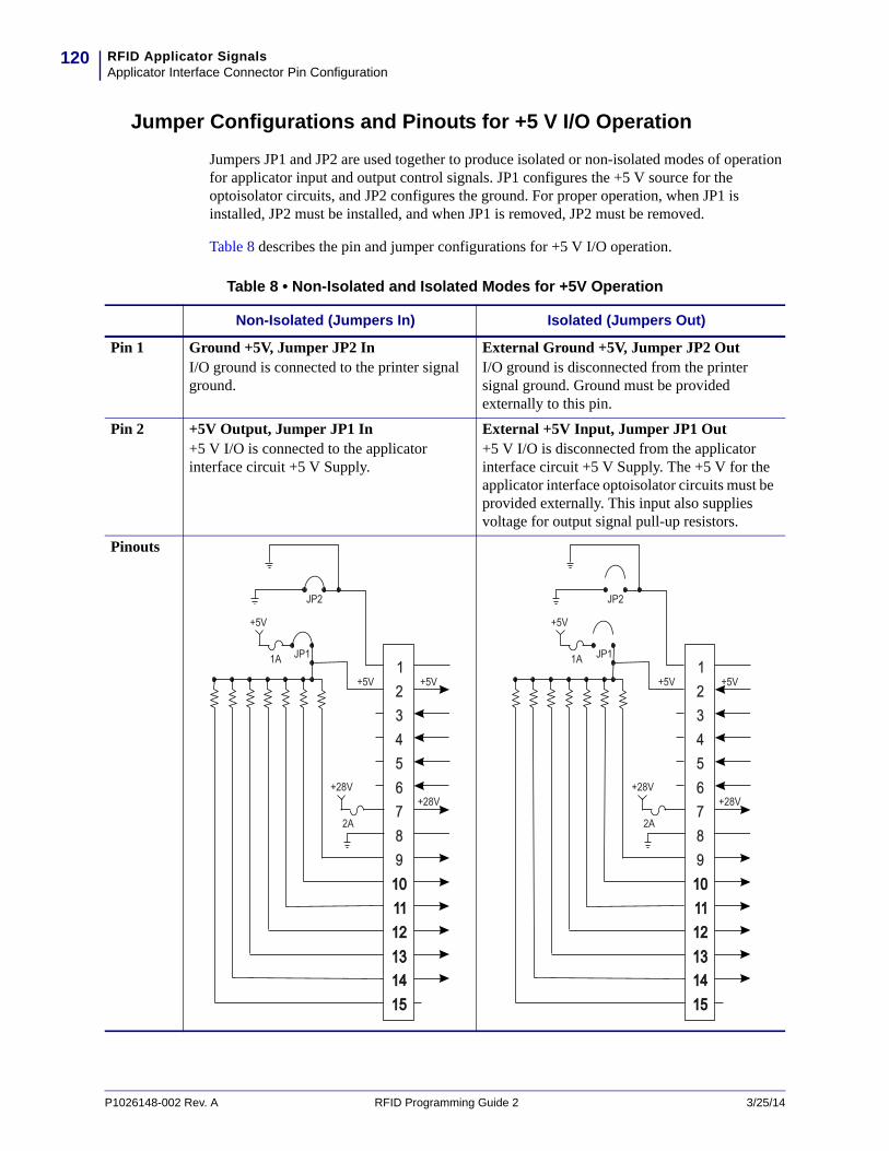
RFID Applicator SignalsApplicator Interface Connector Pin Configuration
120
Jumper Configurations and Pinouts for +5 V I/O Operation
Jumpers JP1 and JP2 are used together to produce isolated or non-isolated modes of operation for applicator input and output control signals. JP1 configures the +5 V source for the optoisolator circuits, and JP2 configures the ground. For proper operation, when JP1 is installed, JP2 must be installed, and when JP1 is removed, JP2 must be removed.
Table 8 describes the pin and jumper configurations for +5 V I/O operation.
Table 8 • Non-Isolated and Isolated Modes for +5V Operation
Non-Isolated (Jumpers In) Isolated (Jumpers Out)
Pin 1 Ground +5V, Jumper JP2 InI/O ground is connected to the printer signal ground.
External Ground +5V, Jumper JP2 OutI/O ground is disconnected from the printer signal ground. Ground must be provided externally to this pin.
Pin 2 +5V Output, Jumper JP1 In+5 V I/O is connected to the applicator interface circuit +5 V Supply.
External +5V Input, Jumper JP1 Out+5 V I/O is disconnected from the applicator interface circuit +5 V Supply. The +5 V for the applicator interface optoisolator circuits must be provided externally. This input also supplies voltage for output signal pull-up resistors.
Pinouts
23456789
1
101011111212131314141515
+5V
JP1
JP2
1A
+5V +5V
+28V+28V
2A
23456789
1
101011111212131314141515
JP1
JP2
+5V
1A
+5V
+28V+28V
+5V
2A
P1026148-002 Rev. A RFID Programming Guide 2 3/25/14
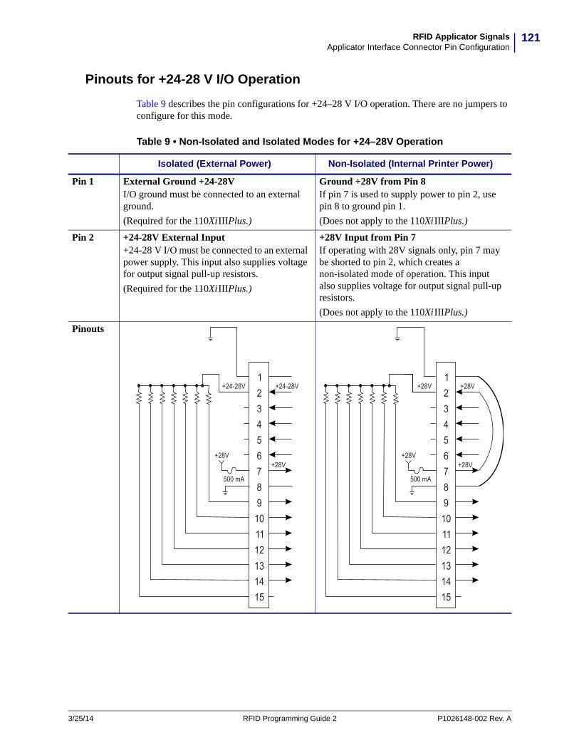
121RFID Applicator SignalsApplicator Interface Connector Pin Configuration
Pinouts for +24-28 V I/O Operation
Table 9 describes the pin configurations for +24–28 V I/O operation. There are no jumpers to configure for this mode.
Table 9 • Non-Isolated and Isolated Modes for +24–28V Operation
Isolated (External Power) Non-Isolated (Internal Printer Power)
Pin 1 External Ground +24-28VI/O ground must be connected to an external ground.
(Required for the 110XiIIIPlus.)
Ground +28V from Pin 8If pin 7 is used to supply power to pin 2, use pin 8 to ground pin 1.
(Does not apply to the 110XiIIIPlus.)
Pin 2 +24-28V External Input+24-28 V I/O must be connected to an external power supply. This input also supplies voltage for output signal pull-up resistors.
(Required for the 110XiIIIPlus.)
+28V Input from Pin 7If operating with 28V signals only, pin 7 may be shorted to pin 2, which creates a non-isolated mode of operation. This input also supplies voltage for output signal pull-up resistors.
(Does not apply to the 110XiIIIPlus.)
Pinouts
23456789
1
101112131415
+24-28V
+28V+28V
500 mA
+24-28V23456789
1
101112131415
+28V +28V
+28V+28V
500 mA
3/25/14 RFID Programming Guide 2 P1026148-002 Rev. A
RFID Applicator SignalsApplicator Interface Connector Pin Configuration
122
Notes • ____________________________________________________________________
__________________________________________________________________________
__________________________________________________________________________
__________________________________________________________________________
__________________________________________________________________________
__________________________________________________________________________
__________________________________________________________________________
__________________________________________________________________________
__________________________________________________________________________
__________________________________________________________________________
P1026148-002 Rev. A RFID Programming Guide 2 3/25/14

Index
Aabsolute mode, 89access password
set via ^RQ, 85set via ^RZ, 101
adaptive antenna element selection, 87Adaptive Antenna Sweep, 24advanced counter reset, 83antenna location, 43antenna port
select using control panel, 31select using ZPL, 100
applicator+24-28V isolated and non-isolated modes, 125+5V isolated and non-isolated modes, 124interface pin configuration, 121timing diagrams for RFID, 118
Ccalibration
from control panel, 29using SGD, 112using ZPL (^HR), 64when to perform, 21
chip serialization, 95contacts, 10creating basic label formats, 34customer service, 10
Ddata log for RFID, 63defaulting the programming position, 21define EPC data structure (^RB), 73display RFID tag data
LCD, 32SGD, 113
double signal modesetting, 90timing diagrams, 120
download firmware, 25
EElectronic Product Code (EPC)
define EPC data structure (^RB), 73EPC structure in RFID labels, 14Gen 2 overview, 15overview, 14write EPC data via ^RQ, 85write EPC data via ^RZ, 101
electrostatic discharge (ESD), 20enable RFID motion (^RM), 82encoding results, 98environmental conditions for RFID labels, 20error codes, 56error handling, 90error messages, 51
Ffirmware upgrades, 25
3/25/14 RFID Programming Guide 2 P1026148-002 Rev. A

Index124
GGen 2
memory map, 15overview, 15setting password or locking tag, 101write EPC data to tag via ^RQ, 85write EPC data to tag via ^RZ, 101
Hhost verification command (^HV), 70
Iinlays, 18isolated mode for applicator control signals
+24-28V operation, 125+5V operation, 124
Jjumper configurations for +24-28V operation, 125jumper configurations for +5V operation, 124
Kkill password
set via ^RQ, 85set via ^RZ, 101
Llabel formats for RFID, 34label placement, 20labels (purchasing RFID labels), 18liability, 2lock RFID tag
Gen 2, 101not Gen 2, 75
lock tag memory or passwords, 79log file for RFID, 63
Mmedia
ordering, 10media (purchasing RFID labels), 18memory bank locking, 79memory map for Gen 2 tags, 15motion in RFID label, 82
Nnon-isolated mode for applicator control signals
+28V operation, 125+5V operation, 124
non-standard label programming, 29number of retries for block (^RR), 87
Oordering ribbon and media, 10
Ppassword for RFID tag, 101password locking, 79permalock tag memory or passwords, 79permanently lock Gen 2 tag data, 101pin configuration for applicator interface, 121placement
labels on items after encoding, 20specifications for transponders, 18
print mode, 71selection via control panel, 28selection via ZPL, 71
programming positionhow to set, 21set through control panel or reset to default, 29set using ZPL, 89setting from control panel, 29setting using SGD, 112setting using ZPL (^HR), 64
Rread power
change through control panel, 30change using ZPL, 99
read RFID tagread or write RFID format (^RF), 75
read unique RFID chip serialization, 95read/write position
set through calibration or reset to default, 29set using ZPL, 89
reader firmware upgrades, 25relative mode, 89report RFID encoding results, 98reset advanced counter, 83reset programming position, 29return data to host computer (^HV), 70return RFID data log to host, 63
P1026148-002 Rev. A RFID Programming Guide 2 3/25/14
125Index
RFIDantenna location, 43change read power through control panel, 30change read power using ZPL, 99change write power through control panel, 30change write power using ZPL, 99create label formats, 34display tag data
LCD, 32SGD, 113
enable motion (^RM), 82error codes and messages, 51error status, 31number of retries for block (^RR), 87power settings, 20RFID setup command (^RS), 89RFID test
control panel, 28SGD command, 114
timing diagrams, 118troubleshooting, 48
RFID countersreset valid label counter by SGD, 105reset void counter by SGD, 106resetting by ZPL, 83
RFID labelslabel formats, 34placement after encoding, 20purchasing, 18storage requirements, 20
RFID modeselection via control panel, 28selection via ZPL, 71
RFID tag ID command (^RI), 77ribbon
ordering, 10
Ssales, 10sample RFID label formats, 35serialization, 95set RFID tag or kill password (^RZ), 101set up RFID information (^RS), 89SGTIN-64 standard programming example, 74SGTIN-96 standard
chip serialization, 96single signal mode
setting, 90timing diagrams, 118
specify number of retries for block (^RR), 87status messages, 51
Ttag type
specify using ZPL, 89technical support, 10temperature requirements for RFID labels, 20timing diagrams
basic, 117RFID, 118
transponder calibrationfrom control panel, 29using SGD, 112using ZPL (^HR), 64when to perform, 21
transponderscharacteristics, 18description, 14placement in labels, 18
troubleshootingRFID error codes and messages, 51RFID problems, 48RFID test
control panel, 28SGD command, 114
3/25/14 RFID Programming Guide 2 P1026148-002 Rev. A

Index126
Uunique RFID chip serialization, 95
Vvalid RFID label counter
reset by SGD, 105reset by ZPL, 83
void handling, 89void RFID label counter
reset by SGD, 106reset by ZPL, 83
Wwrite data to tag
via ^RQ, 85via ^RZ, 101
write powerchange through control panel, 30change using ZPL, 99
write RFID format (^RF), 75
ZZebra Programming Language (ZPL II)
^HL or ~HL, Return RFID Data Log to Host (^HL or ~HL), 63
^HR, Calibrate RFID Transponder, 64overview, 62^RB, Define EPC Data Structure, 73^RF, Read or Write RFID Format, 75RFID label formats, 34^RI, Get RFID Tag ID, 77^RL, Lock/Unlock RFID Tag Memory, 79^RM, Enable RFID Motion, 82^RQ, Quick Write EPC Data and Passwords, 85^RR, Specify RFID Retries for a Block, 87^RS, RFID Setup, 89^RU, read unique RFID chip serialization, 95~RV, Report RFID Encoding Results, 98^RW, Set RFID Read and Write Power, 99^RZ, Set RFID Tag Password and Lock Tag, 101
P1026148-002 Rev. A RFID Programming Guide 2 3/25/14


Zebra Technologies Corporation Zebra Technologies Corporation475 Half Day Road, Suite 500Lincolnshire, IL 60069 USAT: +1 847 634 6700Toll-free +1 866 230 9494F: +1 847 913 8766
Zebra Technologies Europe Limited Dukes MeadowMillboard RoadBourne EndBuckinghamshire, SL8 5XF, UK
T: +44 (0)1628 556000F: +44 (0)1628 556001
Zebra Technologies Asia Pacific, LLC 120 Robinson Road#06-01 Parakou BuildingSingapore 068913T: +65 6858 0722F: +65 6885 0838
http://www.zebra.com
© 2014 ZIH Corp.
P1026148-002


