Page 1
Hydraulic Mining Excavator
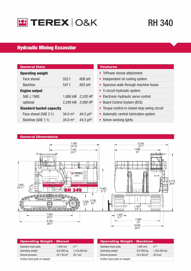
RH 340
General Data
Operating weightFace shovel 552 t 608 sht
Backhoe 547 t 603 sht
Engine outputSAE J 1995 1,880 kW 2,520 HP
optional 2,240 kW 3,000 HP
Standard bucket capacityFace shovel (SAE 2:1) 34.0 m³ 44.5 yd³
Backhoe (SAE 1:1) 34.0 m³ 44.5 yd³
Features
TriPower shovel attachment
Independent oil cooling system
Spacious walk-through machine house
5-circuit-hydraulic system
Electronic-hydraulic servo control
Board Control System (BCS)
Torque control in closed-loop swing circuit
Automatic central lubrication system
Xenon working lights
General Dimensions
Operating Weight - Shovel
Standard track pads 1,400 mm 4’7’’
Operating weight 552,000 kg 1,216,940 lbs
Ground pressure 24.7 N/cm² 30.7 psi
Further track pads on request
Operating Weight - Backhoe
Standard track pads 1,400 mm 4’7’’
Operating weight 547,000 kg 1,205,920 lbs
Ground pressure 24.5 N/cm² 30.9 psi
Further track pads on request
8,77028’9’’
1,1203’8’’
7,58024’10’’7,35024’1’’
7,00023’
8,25027’1’’
7,60024’11’’
9,23030’3“
7,09023’3“
2,5008’2’’
6,46521’3’’
2,7909’2’’
8,03026’4’’
7,00023’
1,4004’7’’
Page 2
2
Diesel Engines (standard)
Make and model 2 x Cummins K 1500-E
Total rated net power ISO 3046/1 1,880 kW (2,520 HP) 1800 min-1
Total rated net power SAE J1349 1,880 kW (2,520 HP) 1800 min-1
Total rated gross power SAE J1995 1,880 kW (2,520 HP) 1800 min-1
Total max. gross power SAE J1995 2,240 kW (3,000 HP) 2100 min-1
No. of cylinders (each engine) 12
Bore 159 mm (6.25 in)
Stroke 159 mm (6.25 in)
Displacement 37.8 l (2,300 in³)
Aspiration Turbocharged and aftercooled
Max. altitude without deration 2,438 m (8,000 ft) a.s.l.
Emission certifi cation US EPA Tier 1
Fuel tank capacity 10,700 l (2,820 US gal)
Hydraulically driven radiator fan with electronically controlled fan speed
Microprocessed engine control
Automatic rev. reduction
Heavy duty air-fi lters, STRATA 1 with automatic dust evacuation
Two-stage fuel fi lter incl. water separator
Additional high capacity water separator
Pre-lube starting system
Eliminator with centrifuge for engine oil fi ltration
Diesel Engines (optional)
Make and model 2 x Cummins QSK 45
Total rated net power ISO 3046/1 2,240 kW (3,000 HP) 1800 min-1
Total rated net power SAE J1349 2,240 kW (3,000 HP) 1800 min-1
Total rated gross power SAE J1995 2,240 kW (3,000 HP) 1800 min-1
Total max. gross power SAE J1995 2,986 kW (4,000 HP) 1900 min-1
No. of cylinders (each engine) 12
Bore 159 mm (6.25 in)
Stroke 190 mm (7.48 in)
Displacement 45 l (2,746 in³)
Aspiration Turbocharged and aftercooled
Max. altitude without deration 4,267 m (14,000 ft) a.s.l.
Emission certifi cation US EPA Tier 1
Electric Motor (optional)
Type Squirrel cage induction motor
Output 1,800 kW
Voltage 4.0 - 7.2 kV ± 10 %
Rated current IN 185 A (at 6.6 kV)
Frequency 50 Hz (60 Hz optional)
Revolutions 1,500 min-1 (1,800 min-1 optional)
Starting current 450% of IN
Custom-made electric motor with increased gap between rotor and stator to withstand severe mining conditions
Power limit control by Pump Management System
Electrical System (diesel drive)
System voltage 24 V
Batteries 6 x 170 Ah - 12 V each
in series/paralell installation 510 Ah - 24 V in total
Alternators 2 x 175 A each
Working spot lights 8 x high brightness Xenon lights
Battery disconnect relais
Emergency stop switches accessible from ground level and in engine module
Hydraulic System with PMS
Main pumps 4 x variable fl ow axial piston pumps
Max. oil fl ow 4 x 925 l/min (4 x 244 US gal/min)
Max. pressure, attachment 32 MPa = 320 bar (4,640 psi)
Max. pressure, travel 36 MPa = 360 bar (5,220 psi)
Swing pumps 4 x reversible swash plate pumps
Max. oil fl ow 4 x 353 l/min (4 x 93 US gal/min)
Max. pressure, swing circuit 35 MPa = 350 bar (5,080 psi)
Total volume of hydraulic oil approx. 8,400 l (2,220 US gal)
Hydraulic tank capacity approx. 6,100 l (1,610 US gal)
Pump Managing System (PMS) contains:
Electronic load limit control
Flow on demand from main pumps depending on joystick position
Automatic regulation of main pumps to zero fl ow without demand
Automatic rpm reduction of engine speed during working breaks
Reduced oil fl ow of main pumps when hydraulic temperature is below / above set values or engine temperature is too high
Pressure cut-off for main pumps
Automatic double-fl ow for all cylinders
Filters:Full-fl ow high-pressure fi lters (100 µm) for the main pumps, installed directly behind each pump
High pressure fi lters (200 µm) for the closed swing circuit
Full-fl ow fi lters (10 µm) for the complete return circuit
Pressure fi lters (40 µm and 6 µm) for servo circuit
Pressure fi lters (40 µm) for the feed pumps of the closed swing circuit
Transmission oil fi lters (40 µm)
Hydraulic Oil Cooling
Oil fl ow of cooling pumps 4 x 500 l/min (4 x 132 US gal/min)
Diameter of fans 4 x 1,170 mm (4 x 46’’)
Cooling system is fully independent of all main circuits, i.e. full cooling capacity is available whenever engine is running
Gear type cooling pumps supplying high volume low pressure oil to fans and aluminium coolers
Fan speed and fl ow of oil to the coolers are thermostatically controlled
Extremely high cooling effi ciency to ensure optimum oil temperature
Swing System
Swing drives 4 compact planetary transmissions with axial piston motors
Parking brakes Wet multiple disc brake, spring loaded / hydraulically released
Max. swing speed 3.9 rpm
Swing ring Triple race roller bearing with sealed internal gearing
Closed-loop swing circuit with torque control
Hydraulic braking of the swing motion by counteracting control
All race ways of swing ring as well as grease bath for internal gearing supplied by automatic central lubrication system
Automatic Lubrication System
Capacity of grease container 1,000 l (264 US gal)
Dual-circuit system with hydraulically driven heavy-duty pump and electronic time relay control to adjust the pause/lube times
Connected to the lubrication system are the swing roller bearing with internal gearing and all pivot points of attachment, bucket and cylinders
System failures displayed by Board Control System
Grease fi lters (200 µm) between service station and container as well as directly behind grease pump
Page 3
3
Operator’s Cab
Operator’s eye level 7.6 m (24’11’’) approx.
Internal dimensions of cab
Length 2,200 mm (7’3’’)
Width 1,600 mm (5’3’’)
Height 2,150 mm (7’1’’)
Pneumatically cushioned and multi-adjustable comfort seat with lumbar support, safety belt, head and arm rests
Safety switch in seat cushion to neutralize automatically the hydraulic controls when operator leaves the seat
Joystick controls integrated in independently adjustable seat consoles
Fold-away auxilliary seat
FOPS (rock guard; approved acc. to DIN ISO 3449) integrated into cab structure
All-round tinted safety glass, armoured windshield and sliding side window
Windshield with parallel intermittent wiper/washer
Roller blind at windshield
Robust instrument panel incl. large and colored BCS screen with transfl ective technology
TEREX O&K Board Control System (BCS) electronic monitoring and data logging system for vital signs and service data of the engines, hydraulic system, pumps, motors and drive system
Undercarriage
Travel speeds (2 stages): Max. 2.0 km/h (1.24 mph)
Max. 1.5 km/h (0.93 mph)
Max. tractive force: 2830 kN (288 t = 635990 lbs)
Gradability: Approximately 54 %
Track pads (each side) 42
Bottom rollers (each side) 7
Support rollers (each side) 2 plus a sliding bar in the centre
Travel drives (each side) 1 planetary transmission with 2 two-stage axial piston motors
Parking brakes Wet multiple disc brake, spring applied / hydraulically released
Cast double-grouser combined pad-links with bushings connected by hardened full fl oating pins
All running surfaces of sprockets, idlers, rollers and pad links as well as teeth contact areas of sprocket and pad links are hardened
Fully hydraulic self-adjusting track tensioning system with membrane accumulator
Automatic hydraulic retarder valve to prevent overspeed on downhill travel
Acoustic travel alarm
Retractable Service Station
Retractable service station installed underneath the engine module and easily accessible from ground. Equipped with:
Quick couplings for:
Diesel fuel
Engine coolant - left/right
Pump transmission gear oil - left/right
Engine oil (oil pan) - left/right
Engine oil (additional tank - optional) - left/right
Hydraulic oil tank
Grease container
CAT jump start socket
Fuel gauge
Attachments
Booms and sticks are torsion resistant, welded box design of high tensile steel with massive steel castings at pivot areas
Welding procedures allow for internal counter-welding (double prep weld) wherever possible
Booms and sticks are stress relieved after welding
Inspection holes in booms (FS & BH) and stick (FS only)
"Pressure-free lowering" of boom (FS and BH) and stick (FS) by means of a fl oat valve
Shovel attachment with TEREX O&K’s patented TriPower kinematics ensuring the following main features:
Horizontal automatic constant-angle bucket guidance
Vertical automatic constant-angle bucket guidance
Automatic roll-back limiter to prevent material spillage
Kinematic assistance to hydraulic forces
Constant boom momentum throughout the whole lift arc
Crowd force assistance
All buckets (FS and BH) are equipped with a universal wear package suitable for all standard applications, which consists of:
Special liner material covering main wear areas inside and outside of bucket
Lip shrouds between teeth
Wing shrouds on side walls
Bottom edge protection
Special wear packages for highly abrasive materials on request
Optional Equipment
General
Export crating
Finishing other than TEREX O&K std. colours (TEREX O&K colour quality)
Customizing of logos as per customer’s specifi cation
Superstructure
Hydraulic service crane on superstructure with auxilliary engine
Mesabi radiators instead of standard radiators
Automatic fi re suppression system
Oil change interval extension for engine oil up to 1000 hrs
Retractable boarding ladder
Grease barrel 200 l (instead of grease container)
Various cold weather packages
Cab
Various heating and airconditioning systems
Roller blinds at all windows
Rear windscreeen wiper
BCS data-transfer-system
Additional instrumentation
Undercarriage
Track pad width 1,600 mm or 1,800 mm
Automatic lubrication of rollers by central lube system
Attachment
Catwalks with rails at boom
Guards for shovel cylinders of FS-attachment
Xenon lighting on boom
Special wear packages
Further optional equipment on request
Page 4
4
m16
15
14
13
12
11
10
9
8
7
6
5
4
3
2
1
0
1
2
3
ft50
45
40
35
30
25
20
15
10
5
0
5
10
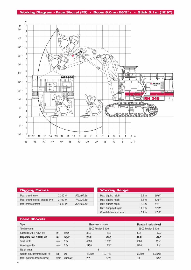
Working Diagram - Face Shovel (FS) - Boom 8.0 m (26’2’’) - Stick 5.1 m (16’9’’)
Digging Forces
Max. crowd force 2,240 kN 503,400 lbs
Max. crowd force at ground level 2,100 kN 471,930 lbs
Max. breakout force 1,640 kN 368,560 lbs
Working Range
Max. digging height 15.4 m 50’6’’
Max. digging reach 16.3 m 53’6’’
Max. digging depth 2.6 m 8’6’’
Max. dumping height 11.5 m 37’9’’
Crowd distance on level 5.4 m 17’9’’
Face Shovels
Type Heavy rock shovel Standard rock shovel
Tooth system ESCO Posilok S 130 ESCO Posilok S 130
Capacity SAE / PCSA 1:1 m3 cuyd 33.0 43.2 39.5 51.7
Capacity SAE / CECE 2:1 m3 cuyd 28.0 36.6 34.0 44.5Total width mm ft:in 4800 15’9’’ 5600 18’4’’
Opening width mm ft:in 2150 7’1’’ 2150 7’1’’
No. of teeth 6 6
Weight incl. universal wear kit kg Ibs 48,600 107,140 52,600 115,960
Max. material density (loose) t/m3 Ibs/cuyd 2.2 3710 1.8 3030
18 17 16 15 14 13 12 11 10 9 8 7 6 5 4 3 2 1 0 m
60 55 50 45 40 35 30 25 20 15 10 5 0 ft
Page 5
5
22 21 20 19 18 17 16 15 14 13 12 11 10 9 8 7 6 5 4 3 2 1 0 m
70 65 60 55 50 45 40 35 30 25 20 15 10 5 0 ft
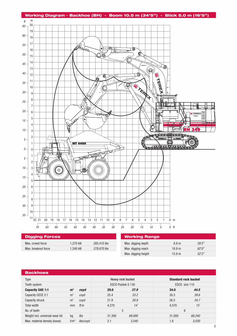
Working Diagram - Backhoe (BH) - Boom 10.5 m (34’5’’) - Stick 5.0 m (16’5’’)m20
19
18
17
16
15
14
13
12
11
10
9
8
7
6
5
4
3
2
1
0
1
2
3
4
5
6
7
8
9
10
11
ft65
60
55
50
45
40
35
30
25
20
15
10
5
0
5
10
15
20
25
30
35
Digging Forces
Max. crowd force 1,270 kN 285,410 lbs
Max. breakout force 1,240 kN 278,670 lbs
Working Range
Max. digging depth 8.9 m 29’2’’
Max. digging reach 18.9 m 62’0’’
Max. digging height 15.9 m 52’2’’
Backhoes
Type Heavy rock bucket Standard rock bucket
Tooth system ESCO Posilok S 130 ESCO size 110
Capacity SAE 1:1 m3 cuyd 29.0 37.9 34.0 44.5Capacity CECE 2:1 m3 cuyd 25.4 33.2 30.3 39.6
Capacity struck m3 cuyd 21.9 28.9 26.5 34.7
Total width mm ft:in 4,270 14’ 4,570 15’
No. of teeth 5 6
Weight incl. universal wear kit kg Ibs 31,300 69,000 31,000 68,340
Max. material density (loose) t/m3 Ibs/cuyd 2.1 3,540 1.8 3,030
Page 6
6
Crates
Content Length Width Height Gross weightmm (ft:in) mm (ft:in) mm (ft:in) kg (lbs)
Radiators with fan; 2 crates each: 2,700 (8’10’’) 2,100 6’11’’) 710 (2’4’’) 1,230 (2,710)
Four swing gears 1,350 (4’5’’) 1,350 (4’5’’) 1,900 (6’3’’) 5,340 (11,770)
Swing ring cover 2,200 (7’3’’) 1,300 (4’3’’) 1,030 (3’5’’) 390 (860)
Swing ring bolts, access ladder, etc. 3,300 (10’10’’) 1,600 (5’3’’) 1,260 (4’2’’) 3,700 (8,160)
Catwalks and other parts 4,950 (16’3’’) 1,900 (6’3’’) 1,740 (5’9’’) 3,500 (7,720)
Grease container with pump 1,700 (5’7’’) 1,300 (4’3’’) 2,050 (6’9’’) 1,470 (3,240)
Barrels (hydraulic oil; grease) 3,700 (12’2’’) 1,350 (4’5’’) 1,350 (4’5’’) 3,150 (6,940)
Barrels (engine oil; antifreeze) 2,000 (6’7’’) 1,350 (4’5’’) 1,400 (4’7’’) 1,380 (3040)
All details provided are for general information only. Exact dimensions subject to selected machine confi guration and fi nal packing list.
General Packing List (approx. values; details may vary depending on scope of supply and destination)
Crawler side frame (2 units)
Width 2,100 mm (6’0’’) Gross weight 48,300 kg (106,480 lbs)
Undercarriage centre frame with swing roller bearing
Width 3,800 mm (12’6’’) Gross weight 42,300 kg (93,250 lbs)
Superstructure centre frame
Width 3,600 mm (11’10’’) Gross weight 60,000 kg (132,280 lbs)
Engine module with diesel engines
Width 7,000 mm (23’) Gross weight K1500E 42,640 kg (94,000 lbs) QSK 45 44,500 kg (98,100 lbs)
Cab pedestal module
Width 2,500 mm (8’2’’) Gross weight 6,500 kg (14,330 lbs)
Oil cooler module
Width 2,120 mm (6’11’’) Gross weight 8,250 kg (18,190 lbs)
Crate with cabin and FOPS
Width 2,600 mm (8’7’’) Gross weight 3,500 kg (7,720 lbs)
Length
Heig
ht
8,800 mm (28’10’’)
2,10
0 m
m(6
’11’
’)
6 tracks consisting of 14 pad links; each:
Width 1,400 mm (4’7’’) Gross weight (each) 11,500 kg (25,350 lbs)
10,200 mm (33’6’’)
3,30
0 m
m (1
0’10
’’)
330 mm (1’1’’)6,900 mm (22’8“)
3,720 mm (12’2’’)
3,70
0 m
m(1
2’2“
)
3,500 mm (11’6’’)
3,07
0 m
m(1
0’1’
’)
Counterweights
Width Gross weightLower part 7,000 mm (23’) 36,900 kg (81,350 lbs)Upper part 7,000 mm (23’) 29,000 kg (63,930 lbs)
1,580 mm(5’2’’)
2,36
0 m
m(7
’9’’)
1,550 mm(5’1’’)
1,75
0 m
m(5
’9’’)
4,110 mm (13’6’’)3,
700
mm
(12’
2’’)
4,000 mm (14’5’’)
3,82
0 m
m(1
2’6’
’)
2,25
0 m
m(7
’5’’)
6,750 mm (22’2’’)
Page 7
7
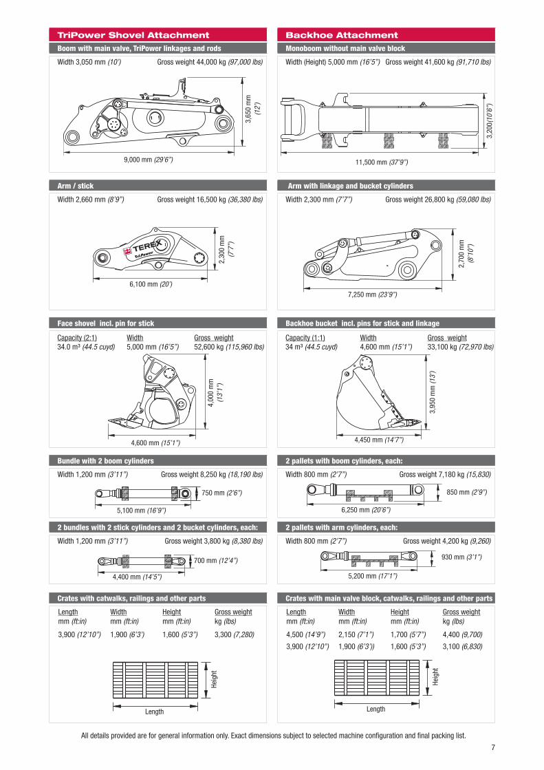
All details provided are for general information only. Exact dimensions subject to selected machine confi guration and fi nal packing list.
Boom with main valve, TriPower linkages and rods
Width 3,050 mm (10’) Gross weight 44,000 kg (97,000 lbs)
TriPower Shovel Attachment Backhoe Attachment
Monoboom without main valve block
Width (Height) 5,000 mm (16’5’’) Gross weight 41,600 kg (91,710 lbs)
Arm / stick
Width 2,660 mm (8’9’’) Gross weight 16,500 kg (36,380 lbs)
Arm with linkage and bucket cylinders
Width 2,300 mm (7’7’’) Gross weight 26,800 kg (59,080 lbs)
Backhoe bucket incl. pins for stick and linkage
Capacity (1:1) Width Gross weight34 m³ (44.5 cuyd) 4,600 mm (15’1’’) 33,100 kg (72,970 lbs)
Bundle with 2 boom cylinders
Width 1,200 mm (3’11’’) Gross weight 8,250 kg (18,190 lbs)
2 bundles with 2 stick cylinders and 2 bucket cylinders, each:
Width 1,200 mm (3’11’’) Gross weight 3,800 kg (8,380 lbs)
2 pallets with boom cylinders, each:
Width 800 mm (2’7’’) Gross weight 7,180 kg (15,830)
Crates with catwalks, railings and other parts
Length Width Height Gross weightmm (ft:in) mm (ft:in) mm (ft:in) kg (lbs)
3,900 (12’10’’) 1,900 (6’3’) 1,600 (5’3’’) 3,300 (7,280)
Face shovel incl. pin for stick
Capacity (2:1) Width Gross weight34.0 m³ (44.5 cuyd) 5,000 mm (16’5’’) 52,600 kg (115,960 lbs)
Length
Heig
ht
Crates with main valve block, catwalks, railings and other parts
Length Width Height Gross weightmm (ft:in) mm (ft:in) mm (ft:in) kg (lbs)
4,500 (14’9’’) 2,150 (7’1’’) 1,700 (5’7’’) 4,400 (9,700)
3,900 (12’10’’) 1,900 (6’3’)) 1,600 (5’3’’) 3,100 (6,830)
9,000 mm (29’6’’)
3,65
0 m
m(1
2’)
6,100 mm (20’)
2,30
0 m
m(7
’7’’)
4,600 mm (15’1’’)
4,00
0 m
m(1
3’1’
’)
5,100 mm (16’9’’)
750 mm (2’6’’)
4,400 mm (14’5’’)
700 mm (12’4’’)
11,500 mm (37’9’’)
3,20
0(10
’6’’)
7,250 mm (23’9’’)
2,70
0 m
m(8
’10’
’)
3,95
0 m
m (1
3’)
4,450 mm (14’7’’)
2 pallets with arm cylinders, each:
Width 800 mm (2’7’’) Gross weight 4,200 kg (9,260)
6,250 mm (20’6’’)
850 mm (2’9’’)
5,200 mm (17’1’’)
930 mm (3’1’’)
Length
Heig
ht
Page 8
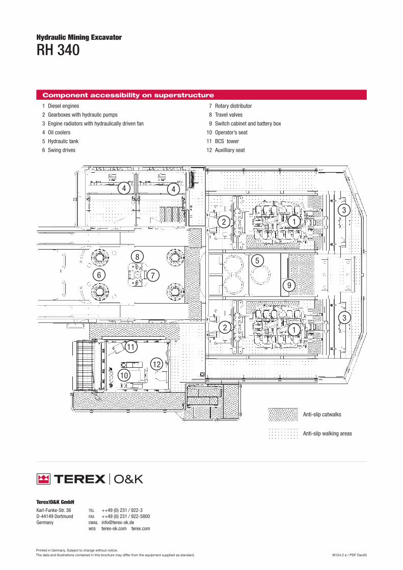
RH 340Hydraulic Mining Excavator
1 Diesel engines
2 Gearboxes with hydraulic pumps
3 Engine radiators with hydraulically driven fan
4 Oil coolers
5 Hydraulic tank
6 Swing drives
Anti-slip catwalks
Anti-slip walking areas
8
79
3
5
6
12
4
1012
11
4
3
12
Printed in Germany. Subject to change without notice.The data and illustrations contained in this brochure may differ from the equipment supplied as standard. M124.2 e / PDF Dec05
Component accessibility on superstructure
7 Rotary distributor
8 Travel valves
9 Switch cabinet and battery box
10 Operator’s seat
11 BCS tower
12 Auxilliary seat
Terex|O&K GmbHKarl-Funke-Str. 36 TEL ++49 (0) 231 / 922-3D-44149 Dortmund FAX ++49 (0) 231 / 922-5800Germany EMAIL [email protected] WEB terex-ok.com terex.com