This document is stored and maintained electronically by Service. All printed copies not bearing this statement in RED are deemed “uncontrolled”. Rheem Australia Pty Ltd ABN 21 098 823 511 S E R V I C E I N S T R U C T I O N S Direct Solar Loline (Electric boosted) TM007 Revision: AD Issued Feb 15 Rheem Solahart Edwards 511270 270SLV 511340 340SLV GTD340 511430 430SLV GTD430 511271 270MDV 511325 320MDV GTD320 511410 410MDV First Issued: 08/01
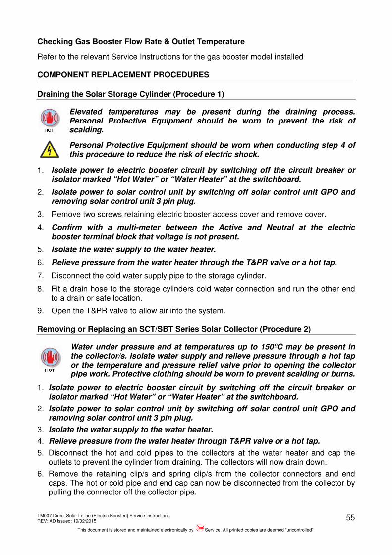
Transcript
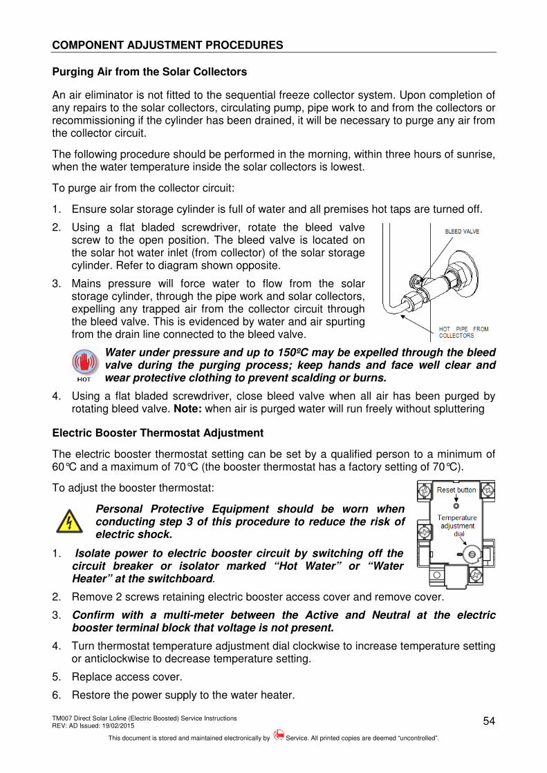
This document is stored and maintained electronically by Service. All printed copies not bearing this statement in RED are deemed “uncontrolled”.
Rheem Australia Pty Ltd ABN 21 098 823 511
SERVICE INSTRUCTIONS Direct Solar Loline (Electric boosted)
DOCUMENT REVISION HISTORY ................................................................................... 68
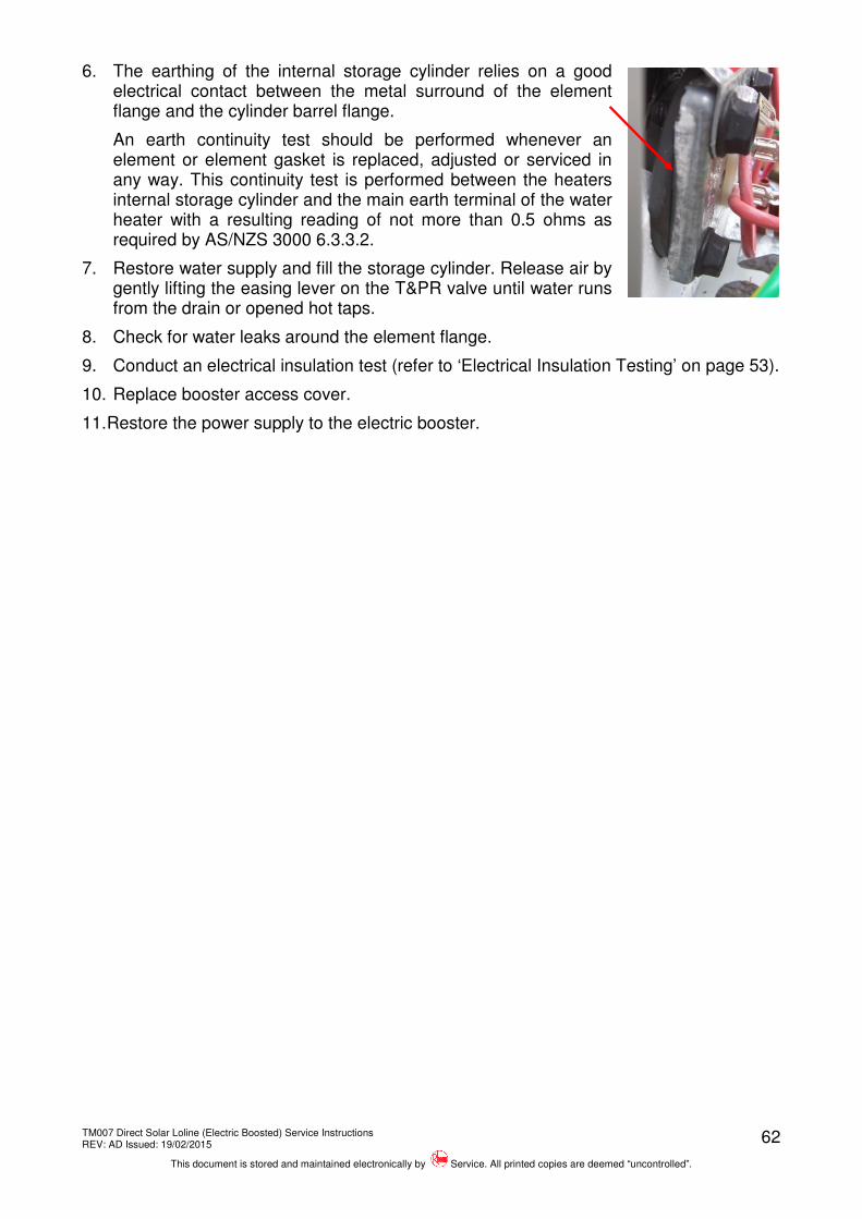
TM007 Direct Solar Loline (Electric Boosted) Service Instructions REV: AD Issued: 19/02/2015
This document is stored and maintained electronically by Service. All printed copies are deemed “uncontrolled”.
3
INTRODUCTION
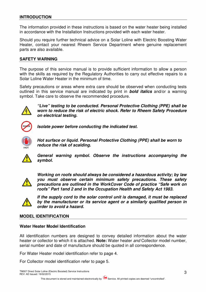
The information provided in these instructions is based on the water heater being installed in accordance with the Installation Instructions provided with each water heater.
Should you require further technical advice on a Solar Loline with Electric Boosting Water Heater, contact your nearest Rheem Service Department where genuine replacement parts are also available. SAFETY WARNING
The purpose of this service manual is to provide sufficient information to allow a person with the skills as required by the Regulatory Authorities to carry out effective repairs to a Solar Loline Water Heater in the minimum of time.
Safety precautions or areas where extra care should be observed when conducting tests outlined in this service manual are indicated by print in bold italics and/or a warning symbol. Take care to observe the recommended procedure.
“Live” testing to be conducted. Personal Protective Clothing (PPE) shall be worn to reduce the risk of electric shock. Refer to Rheem Safety Procedure on electrical testing.
Isolate power before conducting the indicated test.
Hot surface or liquid. Personal Protective Clothing (PPE) shall be worn to reduce the risk of scalding.
General warning symbol. Observe the instructions accompanying the symbol.
Working on roofs should always be considered a hazardous activity; by law you must observe certain minimum safety precautions. These safety precautions are outlined in the WorkCover Code of practice “Safe work on roofs” Part 1and 2 and in the Occupation Health and Safety Act 1983.
If the supply cord to the solar control unit is damaged, it must be replaced by the manufacturer or its service agent or a similarly qualified person in order to avoid a hazard.
MODEL IDENTIFICATION
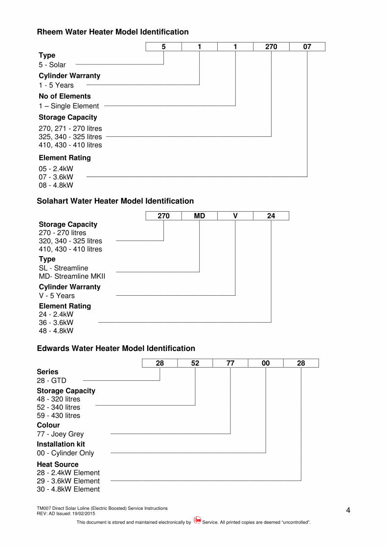
Water Heater Model Identification All identification numbers are designed to convey detailed information about the water heater or collector to which it is attached. Note: Water heater and Collector model number, serial number and date of manufacture should be quoted in all correspondence.
For Water Heater model identification refer to page 4.
For Collector model identification refer to page 5.
TM007 Direct Solar Loline (Electric Boosted) Service Instructions REV: AD Issued: 19/02/2015
This document is stored and maintained electronically by Service. All printed copies are deemed “uncontrolled”.
Heat Source 28 - 2.4kW Element 29 - 3.6kW Element 30 - 4.8kW Element
TM007 Direct Solar Loline (Electric Boosted) Service Instructions REV: AD Issued: 19/02/2015
This document is stored and maintained electronically by Service. All printed copies are deemed “uncontrolled”.
5
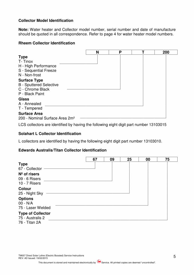
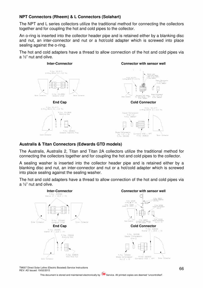
Collector Model Identification Note: Water heater and Collector model number, serial number and date of manufacture should be quoted in all correspondence. Refer to page 4 for water heater model numbers. Rheem Collector Identification N P T 200 Type T- Tinox H - High Performance S - Sequential Freeze N - Non-frost
Surface Type B - Sputtered Selective C - Chrome Black P - Black Paint
Glass A - Annealed T - Tempered
Surface Area 200 - Nominal Surface Area 2m²
LCS collectors are identified by having the following eight digit part number 13103015 Solahart L Collector Identification
L collectors are identified by having the following eight digit part number 13103010. Edwards Australis/Titan Collector Identification 67 09 25 00 75 Type 67 - Collector
Nº of risers 09 - 6 Risers 10 - 7 Risers
Colour 25 - Night Sky
Options 00 - N/A 75 - Laser Welded
Type of Collector
75 - Australis 2 76 - Titan 2A
TM007 Direct Solar Loline (Electric Boosted) Service Instructions REV: AD Issued: 19/02/2015
This document is stored and maintained electronically by Service. All printed copies are deemed “uncontrolled”.
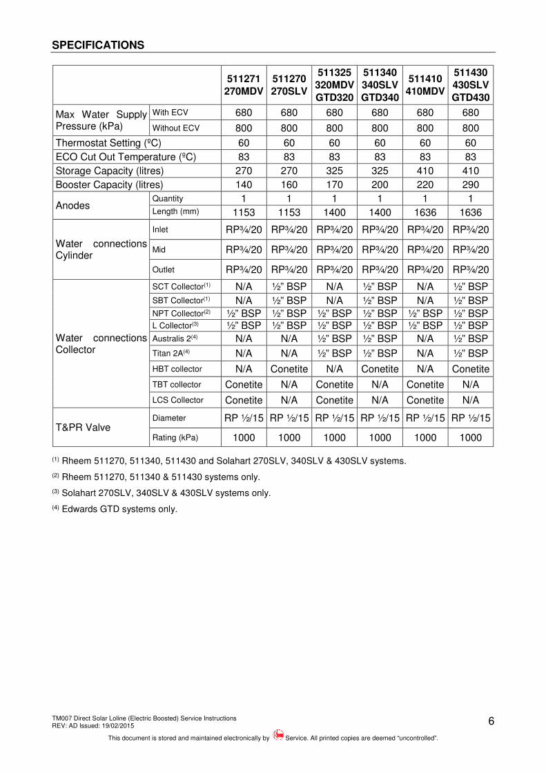
(3) Solahart 270SLV, 340SLV & 430SLV systems only.
(4) Edwards GTD systems only.
TM007 Direct Solar Loline (Electric Boosted) Service Instructions REV: AD Issued: 19/02/2015
This document is stored and maintained electronically by Service. All printed copies are deemed “uncontrolled”.
7
PREVENTATIVE MAINTENANCE
TO BE DONE BY QUALIFIED PERSONS
Annual Service
It is suggested for peak performance that the water heater be serviced annually.
1. Check for discharge from the T&PR valve. Whilst the booster is off, and during periods of low solar contribution there should be no discharge of water. When the booster is operating or during periods of high solar contribution, a small discharge of water may be evident. Operate the valve-easing lever to ensure the valve opens and resets properly. Always open and close the valve gently.
2. Check for leaks at the collector connectors, the hot and cold pipe and all cylinder fittings.
3. Check the collector glass is not cracked and the absorber plate finish is not deteriorating.
4. Confirm all supports and anchors retaining the collector/s to the roof are present, firmly fixed and in good condition.
5. Clean the collector glass. Do not stand on the collectors while cleaning.
6. Check for signs of plant or tree growth that may be shading the collectors. Advise customer to have pruned if possible.
7. Check for signs of excessive corrosion on the water heater jacket, collector panels and roof stand if fitted.
8. Isolate power to the electric booster and check all electrical connections for signs of overheating due to poor connection.
9. If an overflow tray is installed, check to ensure the overflow tray drain pipe is not blocked.
10. Conduct an electrical insulation test on the electric booster circuit (refer to ‘Electrical Insulation Testing’ on page 53).
Major Five Year Service
It is recommended a major five year service be conducted on the solar water heater.
1. Replace pressure temperature relief valve.
2. Inspect and flush expansion control valve (if fitted) and replace if required.
3. Inspect and if required, replace the anode. If the anode is not replaced, it should be replaced within three years of this service.
4. Check the electric element(s) for excessive calcium build up or corrosion and replace if required.
5. Check the solar control unit for correct operation.
6. Clean solar collector glass if required.
7. Flush solar collectors (refer to “Flushing the Solar Collectors” on page 8).
8. Visually check system for any potential problems.
9. Inspect all plumbing and electrical connections.
10. If a safety tray is installed, check to ensure the safety tray drain pipe is not blocked.
TM007 Direct Solar Loline (Electric Boosted) Service Instructions REV: AD Issued: 19/02/2015
This document is stored and maintained electronically by Service. All printed copies are deemed “uncontrolled”.
8
Flushing the Solar Collectors
It may be necessary to flush the solar collectors if there is sediment in the water supply. It is recommended that the solar collectors are flushed every five years. This will assist in keeping the solar collectors, solar cold pipe and solar hot pipe clear of sediment (refer to ‘Major Five Year Service’ on page 7). The following procedure should be performed in the morning, within three hours of sunrise, when the water temperature inside the solar collectors is lowest.
To flush the solar collectors:
1. Open a hot water tap and allow water to run for five (5) minutes prior to flushing solar collectors.
2. Close the hot tap.
3. Wait a further five (5) minutes before attempting to flush the solar collectors. This will assist in the transfer of any high temperature water in the solar collectors to the solar storage cylinder.
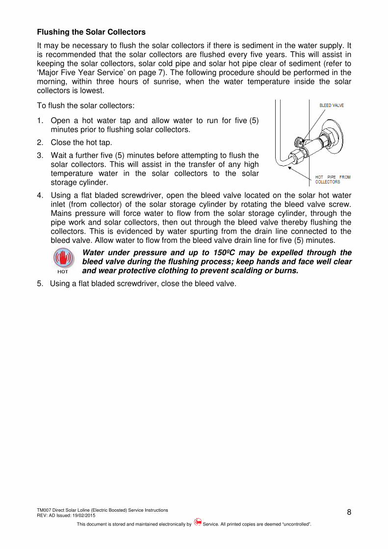
4. Using a flat bladed screwdriver, open the bleed valve located on the solar hot water inlet (from collector) of the solar storage cylinder by rotating the bleed valve screw. Mains pressure will force water to flow from the solar storage cylinder, through the pipe work and solar collectors, then out through the bleed valve thereby flushing the collectors. This is evidenced by water spurting from the drain line connected to the bleed valve. Allow water to flow from the bleed valve drain line for five (5) minutes.
Water under pressure and up to 150ºC may be expelled through the bleed valve during the flushing process; keep hands and face well clear and wear protective clothing to prevent scalding or burns.
5. Using a flat bladed screwdriver, close the bleed valve.
TM007 Direct Solar Loline (Electric Boosted) Service Instructions REV: AD Issued: 19/02/2015
This document is stored and maintained electronically by Service. All printed copies are deemed “uncontrolled”.
9
PRODUCT CHANGES
Replacement of HBT with LCS collector - Rheem 511 models
As of March 2015 the 511 Loline models will have the option of being fitted with high performance LCS collectors in lieu of the obsolete HBT collector. The LCS model is identical to the HBT200 collector in terms of performance and dimensions and is a direct replacement. The difference between the two collectors is the encasing tray material. The LCS collector has an aluminium tray, whereas the HBT200 has a Zincalume tray. Edwards GTD Loline Edwards GTD models ceased production from 3/2013. All current Rheem 511 Loline parts are able to be fitted to an existing GTD Loline unit if required. Solar Loline Upgrade - 11/12 All models within the Solar Loline range underwent a number of modifications in November 2012 in order to improve solar performance. This upgrade included modifications to the storage tank and ground kit as follows: Storage tank: A new range of tanks with revised part numbers, boost position and optimised solar return points were released. New model details are:
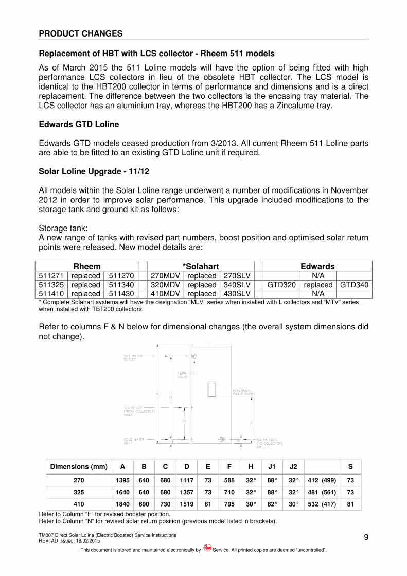
Rheem *Solahart Edwards 511271 replaced 511270 270MDV replaced 270SLV N/A 511325 replaced 511340 320MDV replaced 340SLV GTD320 replaced GTD340 511410 replaced 511430 410MDV replaced 430SLV N/A * Complete Solahart systems will have the designation “MLV” series when installed with L collectors and “MTV” series when installed with TBT200 collectors. Refer to columns F & N below for dimensional changes (the overall system dimensions did not change).
Refer to Column “F” for revised booster position. Refer to Column “N” for revised solar return position (previous model listed in brackets).
TM007 Direct Solar Loline (Electric Boosted) Service Instructions REV: AD Issued: 19/02/2015
This document is stored and maintained electronically by Service. All printed copies are deemed “uncontrolled”.
10
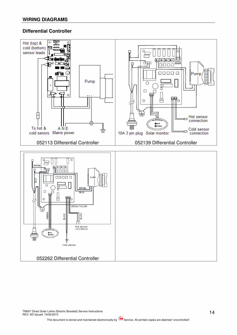
Ground Kit: A new ground kit (299280) was introduced which is similar to the superseded version (299121) with the following differences: Differential Controller
A revised printed circuit board (052262) is fitted in place of existing (052139). The firmware is changed so that an optimised 3-stage flow rate control has been implemented to maximise tank stratification. The PCB is available through Spare Parts and can be retrofitted to any existing solar controller units manufactured from January 2007.
Solar Non Return Valve
A new solar non return valve (088880 – RMC ½” x ¾” SNR505) replaces the current solar non return valve (088071 – RMC SNR502). The new valve has the internal workings made from a higher temperature resistant material than the previous valve. The new valve can be retrofitted to any existing Loline system.
Air Bleed Valve
A new air bleed valve (220344 - RMC ½” x 1” BV1525HT) replaces the current air bleed valve (220340). The new valve incorporates a brass / chrome ball valve providing higher temperature resistance than the previous valve. The new valve can be retrofitted to any existing Loline system.
Addition of TBT collector – Rheem & Solahart Models
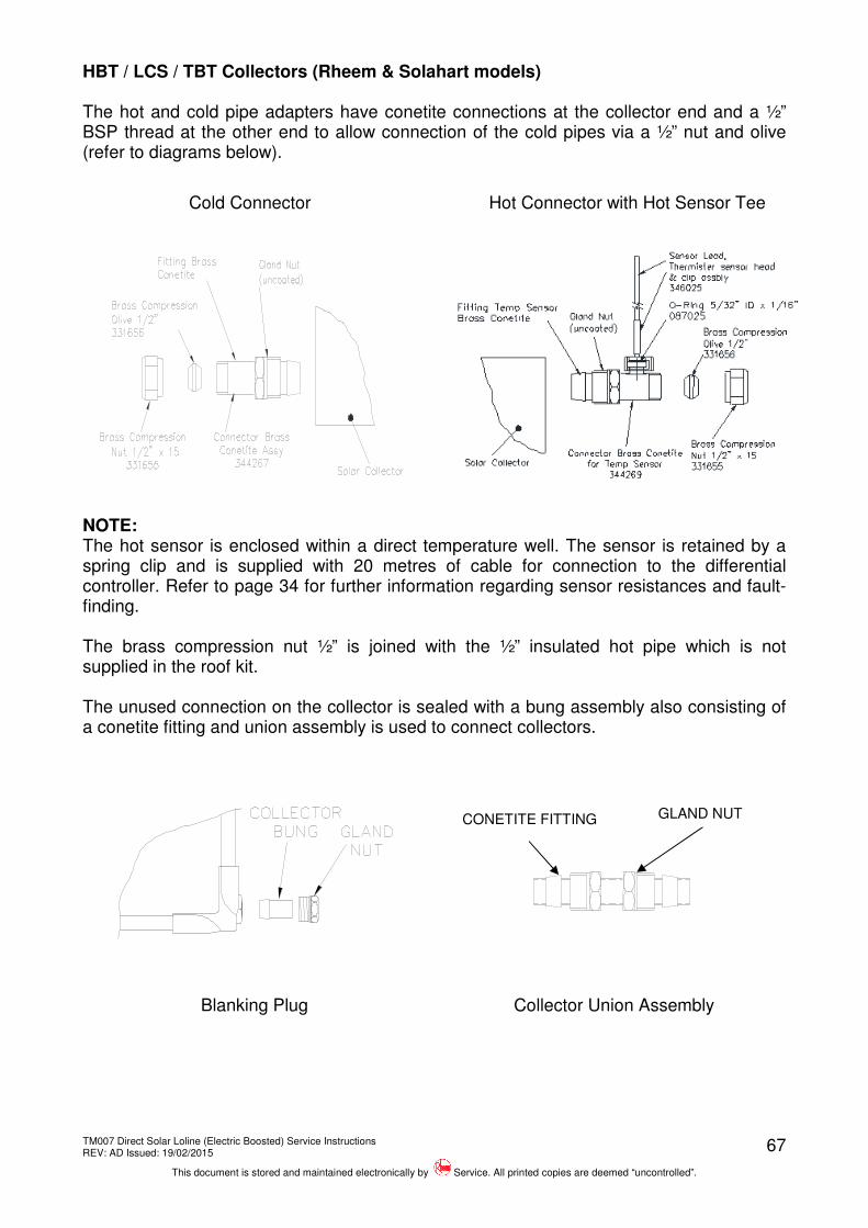
As of November 2012, Rheem & Solahart Loline models will have the option of being fitted with high performance TBT collectors. The TBT collector has different overall dimensions compared with all other collectors and utilises conetite connections. ST12 Replaced with ST13 Thermostat
The ST13 solar thermostat (052072) was introduced in October 2012 as a replacement for the ST12 thermostat to avoid nuisance tripping of the ECO due to high solar gain. Previously when the ST12 ECO tripped (open circuited) a manual reset was required each time the ECO temperature was reached regardless of solar or electric booster heating. The ST13 ECO will auto reset should it trip out during a solar heating cycle, however if the ECO temperature is reached during electric booster operation, the ECO will permanently open and cannot be reset in which case the thermostat will require replacement. The ST13 solar thermostat is a direct replacement for the ST12 thermostat and is wired in the same manner as the ST12 thermostat. Addition of HBT collector - Rheem 511 models
As of October 2011 the 511 Loline models will have the option of being fitted with high performance HBT collectors. The HBT collector has the same overall dimensions as NPT collector but utilises conetite connections rather than the M33 style connections. The HBT collector is fitted with a high performance copper absorber plate that has a sputtered selective surface to improve solar efficiency.
TM007 Direct Solar Loline (Electric Boosted) Service Instructions REV: AD Issued: 19/02/2015
This document is stored and maintained electronically by Service. All printed copies are deemed “uncontrolled”.
11
Differential Controller, Solar Monitor & Circulator Upgrade 01/07
A revised differential controller, part number 052139 was introduced to all models manufactured from January 2007. The original differential controller, part number 052113 is no longer available as a spare part.
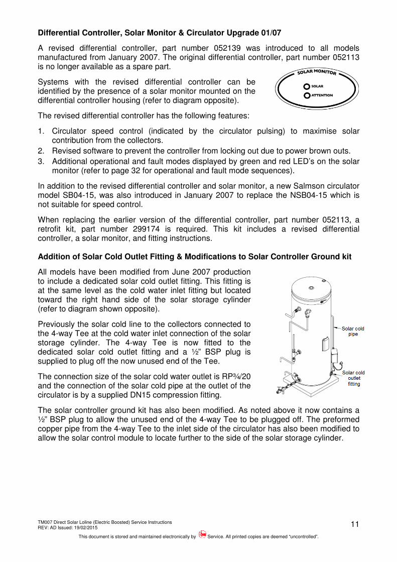
Systems with the revised differential controller can be identified by the presence of a solar monitor mounted on the differential controller housing (refer to diagram opposite).
The revised differential controller has the following features:
1. Circulator speed control (indicated by the circulator pulsing) to maximise solar contribution from the collectors.
2. Revised software to prevent the controller from locking out due to power brown outs.
3. Additional operational and fault modes displayed by green and red LED’s on the solar monitor (refer to page 32 for operational and fault mode sequences).
In addition to the revised differential controller and solar monitor, a new Salmson circulator model SB04-15, was also introduced in January 2007 to replace the NSB04-15 which is not suitable for speed control.
When replacing the earlier version of the differential controller, part number 052113, a retrofit kit, part number 299174 is required. This kit includes a revised differential controller, a solar monitor, and fitting instructions. Addition of Solar Cold Outlet Fitting & Modifications to Solar Controller Ground kit
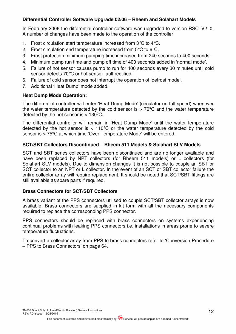
All models have been modified from June 2007 production to include a dedicated solar cold outlet fitting. This fitting is at the same level as the cold water inlet fitting but located toward the right hand side of the solar storage cylinder (refer to diagram shown opposite).
Previously the solar cold line to the collectors connected to the 4-way Tee at the cold water inlet connection of the solar storage cylinder. The 4-way Tee is now fitted to the dedicated solar cold outlet fitting and a ½” BSP plug is supplied to plug off the now unused end of the Tee.
The connection size of the solar cold water outlet is RP¾/20 and the connection of the solar cold pipe at the outlet of the circulator is by a supplied DN15 compression fitting.
The solar controller ground kit has also been modified. As noted above it now contains a ½” BSP plug to allow the unused end of the 4-way Tee to be plugged off. The preformed copper pipe from the 4-way Tee to the inlet side of the circulator has also been modified to allow the solar control module to locate further to the side of the solar storage cylinder.
TM007 Direct Solar Loline (Electric Boosted) Service Instructions REV: AD Issued: 19/02/2015
This document is stored and maintained electronically by Service. All printed copies are deemed “uncontrolled”.
12
Differential Controller Software Upgrade 02/06 – Rheem and Solahart Models
In February 2006 the differential controller software was upgraded to version RSC_V2_0. A number of changes have been made to the operation of the controller
1. Frost circulation start temperature increased from 3°C to 4°C.
2. Frost circulation end temperature increased from 5°C to 6°C.
3. Frost protection minimum pumping time increased from 240 seconds to 400 seconds.
4. Minimum pump run time and pump off time of 400 seconds added in ‘normal mode’.
5. Failure of hot sensor causes pump to run for 400 seconds every 30 minutes until cold sensor detects 70°C or hot sensor fault rectified.
6. Failure of cold sensor does not interrupt the operation of ‘defrost mode’.
7. Additional ‘Heat Dump’ mode added.
Heat Dump Mode Operation:
The differential controller will enter ‘Heat Dump Mode’ (circulator on full speed) whenever the water temperature detected by the cold sensor is > 70ºC and the water temperature detected by the hot sensor is > 130ºC.
The differential controller will remain in ‘Heat Dump Mode’ until the water temperature detected by the hot sensor is < 110ºC or the water temperature detected by the cold sensor is > 75ºC at which time ‘Over Temperature Mode’ will be entered. SCT/SBT Collectors Discontinued – Rheem 511 Models & Solahart SLV Models
SCT and SBT series collectors have been discontinued and are no longer available and have been replaced by NPT collectors (for Rheem 511 models) or L collectors (for Solahart SLV models). Due to dimension changes it is not possible to couple an SBT or SCT collector to an NPT or L collector. In the event of an SCT or SBT collector failure the entire collector array will require replacement. It should be noted that SCT/SBT fittings are still available as spare parts if required. Brass Connectors for SCT/SBT Collectors
A brass variant of the PPS connectors utilised to couple SCT/SBT collector arrays is now available. Brass connectors are supplied in kit form with all the necessary components required to replace the corresponding PPS connector.
PPS connectors should be replaced with brass connectors on systems experiencing continual problems with leaking PPS connectors i.e. installations in areas prone to severe temperature fluctuations.
To convert a collector array from PPS to brass connectors refer to ‘Conversion Procedure – PPS to Brass Connectors’ on page 64.
TM007 Direct Solar Loline (Electric Boosted) Service Instructions REV: AD Issued: 19/02/2015
This document is stored and maintained electronically by Service. All printed copies are deemed “uncontrolled”.
13
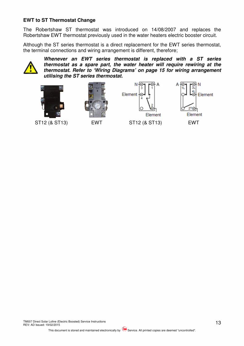
EWT to ST Thermostat Change
The Robertshaw ST thermostat was introduced on 14/08/2007 and replaces the Robertshaw EWT thermostat previously used in the water heaters electric booster circuit.
Although the ST series thermostat is a direct replacement for the EWT series thermostat, the terminal connections and wiring arrangement is different, therefore;
Whenever an EWT series thermostat is replaced with a ST series thermostat as a spare part, the water heater will require rewiring at the thermostat. Refer to ‘Wiring Diagrams’ on page 15 for wiring arrangement utilising the ST series thermostat.
ST12 (& ST13) EWT ST12 (& ST13) EWT
TM007 Direct Solar Loline (Electric Boosted) Service Instructions REV: AD Issued: 19/02/2015
This document is stored and maintained electronically by Service. All printed copies are deemed “uncontrolled”.
TM007 Direct Solar Loline (Electric Boosted) Service Instructions REV: AD Issued: 19/02/2015
This document is stored and maintained electronically by Service. All printed copies are deemed “uncontrolled”.
15
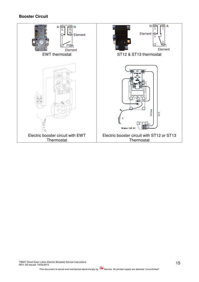
Booster Circuit
EWT thermostat ST12 & ST13 thermostat
Electric booster circuit with EWT Thermostat
Electric booster circuit with ST12 or ST13 Thermostat
TM007 Direct Solar Loline (Electric Boosted) Service Instructions REV: AD Issued: 19/02/2015
This document is stored and maintained electronically by Service. All printed copies are deemed “uncontrolled”.
16
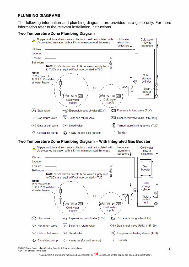
PLUMBING DIAGRAMS
The following information and plumbing diagrams are provided as a guide only. For more information refer to the relevant Installation Instructions.
Two Temperature Zone Plumbing Diagram
Two Temperature Zone Plumbing Diagram – With Integrated Gas Booster
TM007 Direct Solar Loline (Electric Boosted) Service Instructions REV: AD Issued: 19/02/2015
This document is stored and maintained electronically by Service. All printed copies are deemed “uncontrolled”.
17
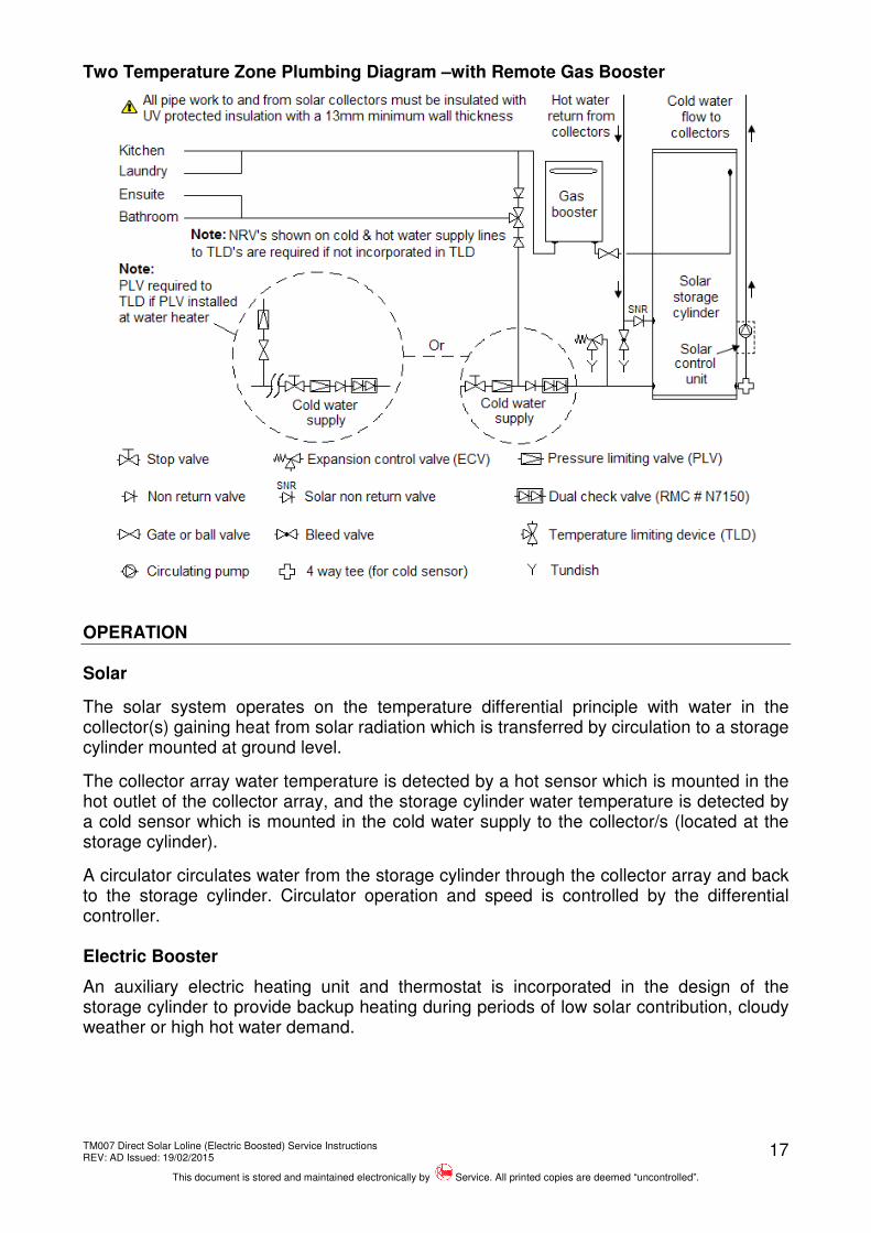
Two Temperature Zone Plumbing Diagram –with Remote Gas Booster
OPERATION
Solar
The solar system operates on the temperature differential principle with water in the collector(s) gaining heat from solar radiation which is transferred by circulation to a storage cylinder mounted at ground level.
The collector array water temperature is detected by a hot sensor which is mounted in the hot outlet of the collector array, and the storage cylinder water temperature is detected by a cold sensor which is mounted in the cold water supply to the collector/s (located at the storage cylinder).
A circulator circulates water from the storage cylinder through the collector array and back to the storage cylinder. Circulator operation and speed is controlled by the differential controller. Electric Booster
An auxiliary electric heating unit and thermostat is incorporated in the design of the storage cylinder to provide backup heating during periods of low solar contribution, cloudy weather or high hot water demand.
TM007 Direct Solar Loline (Electric Boosted) Service Instructions REV: AD Issued: 19/02/2015
This document is stored and maintained electronically by Service. All printed copies are deemed “uncontrolled”.
The differential controller receives information from the hot sensor which measures the water temperature at the collectors, and the cold sensor which measures the water temperature at the bottom of the storage cylinder.
Differential Controller Operating Modes Run Mode
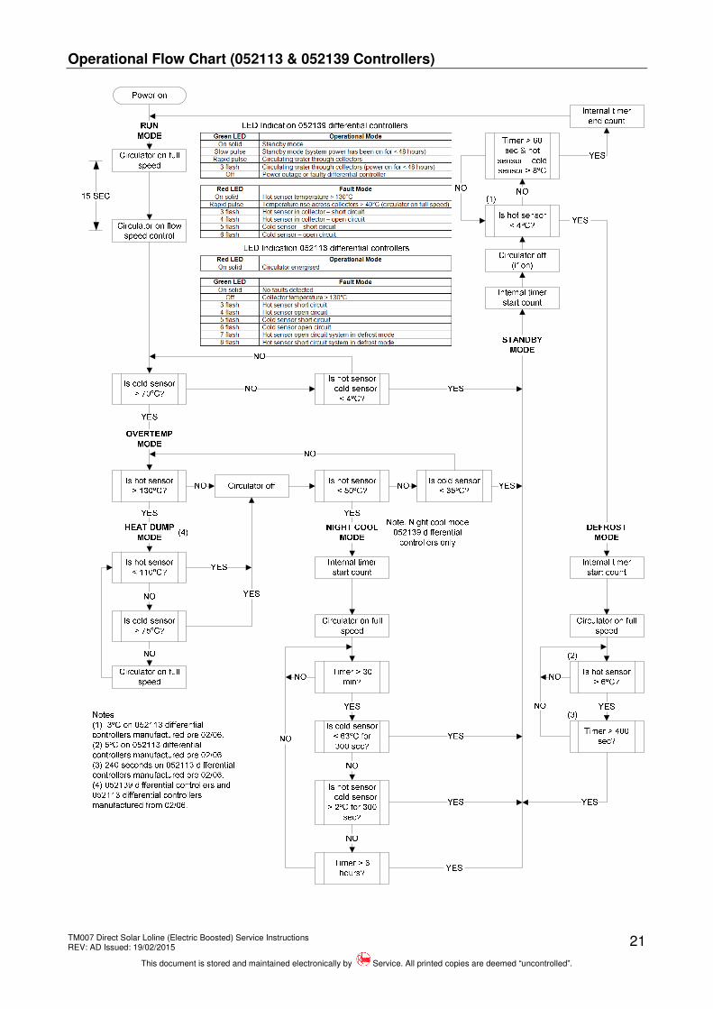
When the difference between the water temperature detected by the hot sensor and that detected by the cold sensor is ≥ 8ºC, the differential controller will energise the circulator.
The circulator moves the colder water in the storage tank up to the collector(s) for heating via the cold pipe and the heated water in the collector(s) down to the storage tank via the hot pipe. NOTE: The flow rate is dependant on the differential controller fitted.
• 052113 Differential Controller – The circulator runs at full speed
• 052139 Differential Controller – The circulator is started at full speed then pulsed at a fixed rate.
The differential controller will de-energise the circulator when the temperature difference between the hot and cold sensors is ≤4 ºC or the cold sensor temperature is ≥ 70ºC and
the hot sensor temperature is < 130ºC.
Standby Mode: The differential controller will enter ‘Standby Mode’ (circulating pump off) when the temperature difference between the hot and cold sensors falls below 4ºC and provided the cold sensor detects ≤ 70ºC.
‘Standby Mode’ prevents the system from operating when solar gain is inadequate. The differential controller will remain in ‘Standby Mode’ for a minimum of 60 seconds and until the water temperature detected by the hot sensor is 8ºC above the water temperature detected by the cold sensor at which time ‘Run Mode’ will be entered.
Defrost Mode: The differential controller will enter ‘Defrost Mode’ (circulator on full speed) whenever the hot sensor detects a water temperature of < 4ºC (such as during periods of frost). Note: < 3 ºC for 052113 differential controllers manufactured pre 02/06.
‘Defrost Mode’ circulates water from the storage cylinder through the solar collector(s) to prevent the solar collector flow and return pipe work from freezing.
The differential controller will remain in ‘Defrost Mode’ for a minimum of 400 seconds and until the water temperature detected by the hot sensor is > 6ºC at which time ‘Standby Mode’ will be entered. Note: minimum of 240 seconds and > 5 ºC for 052113 differential controllers manufactured pre 02/06.
TM007 Direct Solar Loline (Electric Boosted) Service Instructions REV: AD Issued: 19/02/2015
This document is stored and maintained electronically by Service. All printed copies are deemed “uncontrolled”.
19
Over Temperature Mode: The differential controller will enter ‘Over Temperature Mode’ (circulator off) whenever the water temperature detected by the cold sensor is > 70ºC.
The differential controller will remain in ‘Over Temperature Mode’ until one of the following conditions occurs:
• If the hot sensor detects a water temperature > 130ºC the differential controller will enter ‘Heat Dump Mode’.
• 052139 differential controllers: If the hot sensor detects a water temperature < 50ºC the differential controller will enter ‘Night Cool Mode’.
• If the cold sensor detects a water temperature of < 35ºC the system will enter ‘Standby Mode’.
Heat Dump Mode – 052139 Differential Controllers & 052113 Differential Controllers Manufactured from 02/06: The differential controller will enter ‘Heat Dump Mode’ (circulator on full speed) whenever the water temperature detected by the cold sensor is > 70ºC and the water temperature detected by the hot sensor is > 130ºC.
‘Heat Dump Mode’ reduces the temperature of the water in the solar collector(s) by transferring (dumping) excess heat from the solar collector(s) into the storage cylinder whilst still preventing the likelihood of extremely hot water being delivered to hot taps and other outlets at uncontrolled water temperatures which may otherwise be near boiling point.
The differential controller will remain in ‘Heat Dump Mode’ until the water temperature detected by the hot sensor is < 110ºC or the water temperature detected by the cold sensor is > 75ºC at which time ‘Over Temperature Mode’ will be entered.
Night Cool Mode – 052139 Differential Controllers Only: The differential controller will enter ‘Night Cool Mode’ (circulator on full speed) whenever the water temperature detected by the cold sensor is > 70ºC and the water temperature detected by the hot sensor is < 50ºC.
‘Night Cool Mode’ reduces the temperature of the water in the storage cylinder by transferring excess heat from the storage cylinder back to the solar collector(s).
The differential controller will remain in ‘Night Cool Mode’ for a minimum of 30 minutes after which time the differential controller will enter ‘Standby Mode’ if any of the following conditions occurs:
• The cold sensor detects a water temperature < 63ºC for a minimum of 300 seconds.
• The hot sensor temperature minus the cold sensor temperature is > 2ºC for a minimum of 300 seconds.
• The differential controller has been in ‘Night Cool Mode’ for more than 6 hours.
TM007 Direct Solar Loline (Electric Boosted) Service Instructions REV: AD Issued: 19/02/2015
This document is stored and maintained electronically by Service. All printed copies are deemed “uncontrolled”.
20
Diagnostics & LED Indication: The differential controller can display operational and fault modes and has inbuilt diagnostics to test the condition of the hot and cold sensors.
On early model 052113 differential controllers a 3 pin plug on the circuit board allows a ‘Sensor LED Test Unit’ part number 890258 (shown opposite) to be connected so as operational and fault modes can be displayed.
Later model 052113 differential controllers have the LED’s (one red and one green) permanently mounted on the differential controllers’ circuit board. Systems with 052139 differential controllers have a remote solar monitor with LED indication (shown opposite).
For information on operational and fault mode indication and their meanings refer to ‘Differential Controller Operational & Fault Modes’ on page 32.
TM007 Direct Solar Loline (Electric Boosted) Service Instructions REV: AD Issued: 19/02/2015
This document is stored and maintained electronically by Service. All printed copies are deemed “uncontrolled”.
22
Differential Controller Operation – 052262
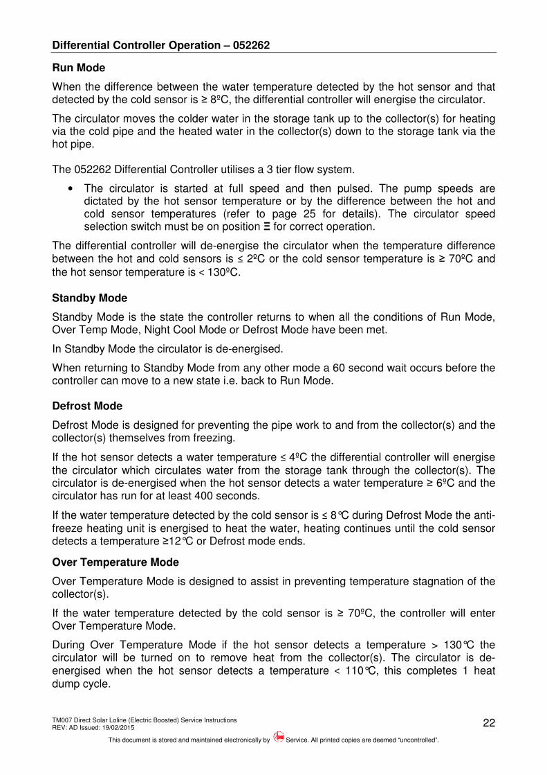
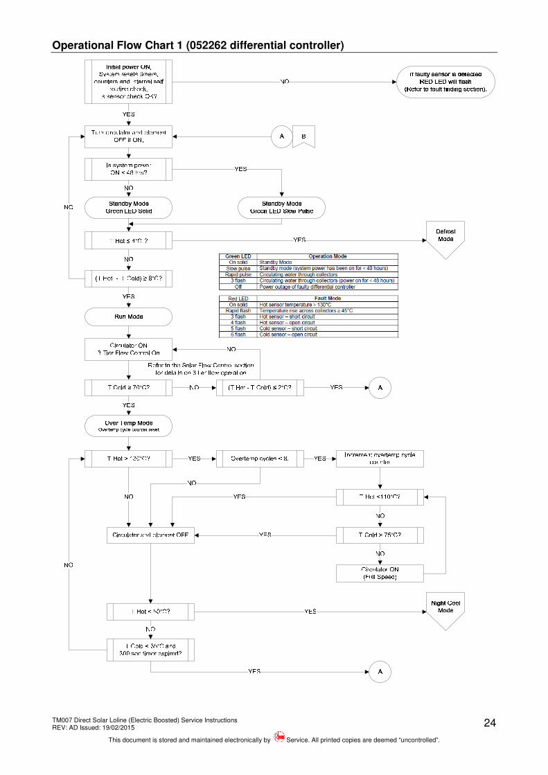
Run Mode
When the difference between the water temperature detected by the hot sensor and that detected by the cold sensor is ≥ 8ºC, the differential controller will energise the circulator.
The circulator moves the colder water in the storage tank up to the collector(s) for heating via the cold pipe and the heated water in the collector(s) down to the storage tank via the hot pipe. The 052262 Differential Controller utilises a 3 tier flow system.
• The circulator is started at full speed and then pulsed. The pump speeds are dictated by the hot sensor temperature or by the difference between the hot and cold sensor temperatures (refer to page 25 for details). The circulator speed selection switch must be on position Ξ for correct operation.
The differential controller will de-energise the circulator when the temperature difference between the hot and cold sensors is ≤ 2ºC or the cold sensor temperature is ≥ 70ºC and
the hot sensor temperature is < 130ºC.
Standby Mode
Standby Mode is the state the controller returns to when all the conditions of Run Mode, Over Temp Mode, Night Cool Mode or Defrost Mode have been met.
In Standby Mode the circulator is de-energised.
When returning to Standby Mode from any other mode a 60 second wait occurs before the controller can move to a new state i.e. back to Run Mode. Defrost Mode
Defrost Mode is designed for preventing the pipe work to and from the collector(s) and the collector(s) themselves from freezing.
If the hot sensor detects a water temperature ≤ 4ºC the differential controller will energise the circulator which circulates water from the storage tank through the collector(s). The circulator is de-energised when the hot sensor detects a water temperature ≥ 6ºC and the circulator has run for at least 400 seconds.
If the water temperature detected by the cold sensor is ≤ 8°C during Defrost Mode the anti-freeze heating unit is energised to heat the water, heating continues until the cold sensor detects a temperature ≥12°C or Defrost mode ends.
Over Temperature Mode
Over Temperature Mode is designed to assist in preventing temperature stagnation of the collector(s).
If the water temperature detected by the cold sensor is ≥ 70ºC, the controller will enter Over Temperature Mode.
During Over Temperature Mode if the hot sensor detects a temperature > 130°C the circulator will be turned on to remove heat from the collector(s). The circulator is de-energised when the hot sensor detects a temperature < 110°C, this completes 1 heat dump cycle.
TM007 Direct Solar Loline (Electric Boosted) Service Instructions REV: AD Issued: 19/02/2015
This document is stored and maintained electronically by Service. All printed copies are deemed “uncontrolled”.
23
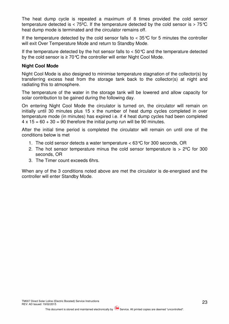
The heat dump cycle is repeated a maximum of 8 times provided the cold sensor temperature detected is < 75ºC. If the temperature detected by the cold sensor is > 75°C heat dump mode is terminated and the circulator remains off.
If the temperature detected by the cold sensor falls to < 35°C for 5 minutes the controller will exit Over Temperature Mode and return to Standby Mode.
If the temperature detected by the hot sensor falls to < 50°C and the temperature detected by the cold sensor is ≥ 70°C the controller will enter Night Cool Mode.
Night Cool Mode
Night Cool Mode is also designed to minimise temperature stagnation of the collector(s) by transferring excess heat from the storage tank back to the collector(s) at night and radiating this to atmosphere.
The temperature of the water in the storage tank will be lowered and allow capacity for solar contribution to be gained during the following day.
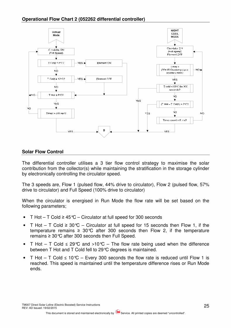
On entering Night Cool Mode the circulator is turned on, the circulator will remain on initially until 30 minutes plus 15 x the number of heat dump cycles completed in over temperature mode (in minutes) has expired i.e. if 4 heat dump cycles had been completed 4 x 15 = 60 + 30 = 90 therefore the initial pump run will be 90 minutes.
After the initial time period is completed the circulator will remain on until one of the conditions below is met
1. The cold sensor detects a water temperature < 63°C for 300 seconds, OR
2. The hot sensor temperature minus the cold sensor temperature is > 2ºC for 300 seconds, OR
3. The Timer count exceeds 6hrs. When any of the 3 conditions noted above are met the circulator is de-energised and the controller will enter Standby Mode.
TM007 Direct Solar Loline (Electric Boosted) Service Instructions REV: AD Issued: 19/02/2015
This document is stored and maintained electronically by Service. All printed copies are deemed “uncontrolled”.
Circulator ON(Full Speed)NO T cold < 63°C for 300 seconds?
NOYES Timer count > 6 hrs?NONOYESYES
Solar Flow Control
The differential controller utilises a 3 tier flow control strategy to maximise the solar contribution from the collector(s) while maintaining the stratification in the storage cylinder by electronically controlling the circulator speed. The 3 speeds are, Flow 1 (pulsed flow, 44% drive to circulator), Flow 2 (pulsed flow, 57% drive to circulator) and Full Speed (100% drive to circulator) When the circulator is energised in Run Mode the flow rate will be set based on the following parameters;
• T Hot – T Cold ≥ 45°C – Circulator at full speed for 300 seconds
• T Hot – T Cold ≥ 30°C – Circulator at full speed for 15 seconds then Flow 1, if the temperature remains ≥ 30°C after 300 seconds then Flow 2, if the temperature remains ≥ 30°C after 300 seconds then Full Speed.
• T Hot – T Cold ≤ 29°C and >10°C – The flow rate being used when the difference between T Hot and T Cold fell to 29°C degrees is maintained.
• T Hot – T Cold ≤ 10°C – Every 300 seconds the flow rate is reduced until Flow 1 is reached. This speed is maintained until the temperature difference rises or Run Mode ends.
TM007 Direct Solar Loline (Electric Boosted) Service Instructions REV: AD Issued: 19/02/2015
This document is stored and maintained electronically by Service. All printed copies are deemed “uncontrolled”.
26
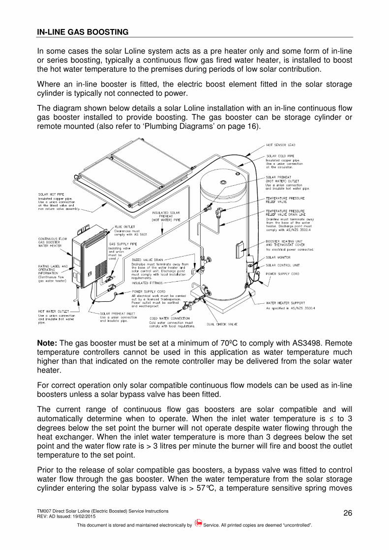
IN-LINE GAS BOOSTING
In some cases the solar Loline system acts as a pre heater only and some form of in-line or series boosting, typically a continuous flow gas fired water heater, is installed to boost the hot water temperature to the premises during periods of low solar contribution.
Where an in-line booster is fitted, the electric boost element fitted in the solar storage cylinder is typically not connected to power.
The diagram shown below details a solar Loline installation with an in-line continuous flow gas booster installed to provide boosting. The gas booster can be storage cylinder or remote mounted (also refer to ‘Plumbing Diagrams’ on page 16).
Note: The gas booster must be set at a minimum of 70ºC to comply with AS3498. Remote temperature controllers cannot be used in this application as water temperature much higher than that indicated on the remote controller may be delivered from the solar water heater.
For correct operation only solar compatible continuous flow models can be used as in-line boosters unless a solar bypass valve has been fitted.
The current range of continuous flow gas boosters are solar compatible and will automatically determine when to operate. When the inlet water temperature is ≤ to 3 degrees below the set point the burner will not operate despite water flowing through the heat exchanger. When the inlet water temperature is more than 3 degrees below the set point and the water flow rate is > 3 litres per minute the burner will fire and boost the outlet temperature to the set point.
Prior to the release of solar compatible gas boosters, a bypass valve was fitted to control water flow through the gas booster. When the water temperature from the solar storage cylinder entering the solar bypass valve is > 57°C, a temperature sensitive spring moves
TM007 Direct Solar Loline (Electric Boosted) Service Instructions REV: AD Issued: 19/02/2015
This document is stored and maintained electronically by Service. All printed copies are deemed “uncontrolled”.
27
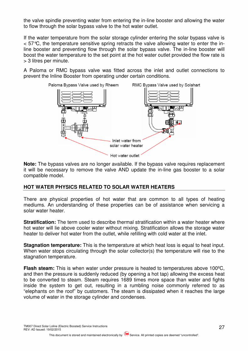
the valve spindle preventing water from entering the in-line booster and allowing the water to flow through the solar bypass valve to the hot water outlet. If the water temperature from the solar storage cylinder entering the solar bypass valve is < 57°C, the temperature sensitive spring retracts the valve allowing water to enter the in-line booster and preventing flow through the solar bypass valve. The in-line booster will boost the water temperature to the set point at the hot water outlet provided the flow rate is > 3 litres per minute.
A Paloma or RMC bypass valve was fitted across the inlet and outlet connections to prevent the Inline Booster from operating under certain conditions.
Note: The bypass valves are no longer available. If the bypass valve requires replacement it will be necessary to remove the valve AND update the in-line gas booster to a solar compatible model. HOT WATER PHYSICS RELATED TO SOLAR WATER HEATERS
There are physical properties of hot water that are common to all types of heating mediums. An understanding of these properties can be of assistance when servicing a solar water heater. Stratification: The term used to describe thermal stratification within a water heater where hot water will lie above cooler water without mixing. Stratification allows the storage water heater to deliver hot water from the outlet, while refilling with cold water at the inlet. Stagnation temperature: This is the temperature at which heat loss is equal to heat input. When water stops circulating through the solar collector(s) the temperature will rise to the stagnation temperature. Flash steam: This is when water under pressure is heated to temperatures above 100ºC, and then the pressure is suddenly reduced (by opening a hot tap) allowing the excess heat to be converted to steam. Steam requires 1689 times more space than water and fights inside the system to get out, resulting in a rumbling noise commonly referred to as “elephants on the roof” by customers. The steam is dissipated when it reaches the large volume of water in the storage cylinder and condenses.
TM007 Direct Solar Loline (Electric Boosted) Service Instructions REV: AD Issued: 19/02/2015
This document is stored and maintained electronically by Service. All printed copies are deemed “uncontrolled”.
28
Density of water: Water is at its maximum density at a temperature of 4ºC. When heated above 4ºC and up to 100ºC, water expands unequally at an average of 1/23rd of its volume. Between 10ºC and 65ºC the expansion is approximately 1/50th of its volume. This is known as thermal expansion, or expansion, and is relieved through the temperature and pressure relief valve (T&PR valve).
Note: Water will expand relative to its rise in temperature. The discharge from the T&PR valve is usually the result of thermal expansion due to heating, in which case the quantity of the discharge will be affected by:
• The amount of water being heated.
• The temperature rise from cold to hot.
• The pressure rating of the T&PR valve.
• The number of times a hot tap is opened during a heating cycle.
• The amount of water lost through dripping taps.
• Faulty non-return valve fitted to cold water inlet.
It should be noted that a T&PR valve should not discharge water due to thermal expansion when the heating cycle is off.
Boiling point of water: The temperature at which water boils is directly related to the pressure the water is subjected to.
• At sea level the boiling point of water is 100ºC.
• Water will boil at below 100ºC if the pressure is below 101kPa (atmospheric pressure at sea level).
• Water will boil at above 100ºC if the pressure is above 101kPa (for example; water at 1000kPa will boil at approximately 183ºC).
Specific heat: The amount of energy required to raise 1kg of a substance by 1ºC. Measured in units of kilo joules (kJ) i.e. 4.2kJ will raise 1 litre (1kg) of water 1ºC. Latent heat (Hidden or invisible heat): The energy required to change the state of a substance (water) into another state without a change in temperature i.e.
• Water to steam and steam to water.
• Water to ice and ice to water.
The latent heat of steam is approximately 6 times the specific heat of water, i.e. to convert water at 100ºC to steam at 100ºC will require approximately 252 kJ/kg.
Freezing of water: Water cooled below 4ºC expands insignificantly until it reaches the point of its changing state into ice, at which time it expands by 1/11th of its volume. Ice contracts on further cooling. Damage to solar collectors can occur when:
1. Water trapped between two plugs of ice is compressed by the ice expansion to a point where the pressure results in a failure of the copper tube.
2. An ice plug forms in a tee or elbow and the expansion cannot be relieved, resulting in a split fitting.
TM007 Direct Solar Loline (Electric Boosted) Service Instructions REV: AD Issued: 19/02/2015
This document is stored and maintained electronically by Service. All printed copies are deemed “uncontrolled”.
29
COMPONENTS AND THEIR FUNCTION
Temperature and Pressure Relief Valve (T&PR): A valve designed to provide automatic relief by discharging water in case of excessive temperature, pressure or both.
Never fit a T&PR Valve with a pressure rating greater than that indicated on the product-rating label.
Outlet Delivery Tube (Dip Tube): A noryl tube installed in the hot water outlet of the water heater cylinder to conduct water from the highest point to the outlet connection. It also acts as a fitting liner.
Fitting Liner: A plastic tube installed in the cold water inlet of the water heater to provide protection against corrosion throughout the life of the water heater.
Solar Cold Pipe (Solar Return): The pipe connecting the solar collectors to the storage water heater through which, the cooler water returns from the storage cylinder to the collectors.
Hot Pipe (Solar Flow): The pipe connecting the solar collectors to the storage cylinder through which solar heated water flows back to the storage cylinder from the collectors.
Circulating Pump: A small centrifugal pump that circulates water through the solar collectors and storage cylinder.
Differential Controller: An electronic control unit that interprets resistance values of the hot and cold sensors to determine when to operate the circulator.
Hot Sensor: A thermistor for sensing water temperature. The hot sensor is fitted into the connector at the hot pipe connection on the solar collector.
Cold Sensor: A thermistor for sensing water temperature. The cold sensor is fitted into a tee at the cold water pickup for the collectors on the storage cylinder.
4 Way Tee (511 Series): A special purpose brass fitting to which the connections for the water heater; cold pipe; cold water supply and cold water sensor are all included.
5 Way Tee (Solar Conversion Kits Only): A special purpose brass fitting to which the connections for the water heater; cold pipe, hot pipe, cold water supply and cold water sensor are all included.
Anode (Sacrificial): A metal alloy electrode installed in the water heater cylinder that by galvanic action protects the cylinder from corrosion.
Thermostat: A device, responsive to temperature, which controls the supply of electrical energy to the booster element to maintain the stored water at the required temperature.
Over Temperature Energy Cut Out (ECO): A safety device incorporated within the thermostat that automatically cuts off the supply of electrical energy to the booster element should the water temperature exceed 83ºC during a heating cycle. If the ECO trips, EWT and ST12 thermostats can be manually reset; ST13 solar thermostats must be replaced as they cannot be reset. DETERMINE CAUSE OF OPERATION.
Heating Unit (Element): A tubular device containing an electric resistance element that converts electrical energy to heat. Standard element ratings are 1.8, 2.4, 3.0, 3.6 and 4.8kW.
TM007 Direct Solar Loline (Electric Boosted) Service Instructions REV: AD Issued: 19/02/2015
This document is stored and maintained electronically by Service. All printed copies are deemed “uncontrolled”.
30
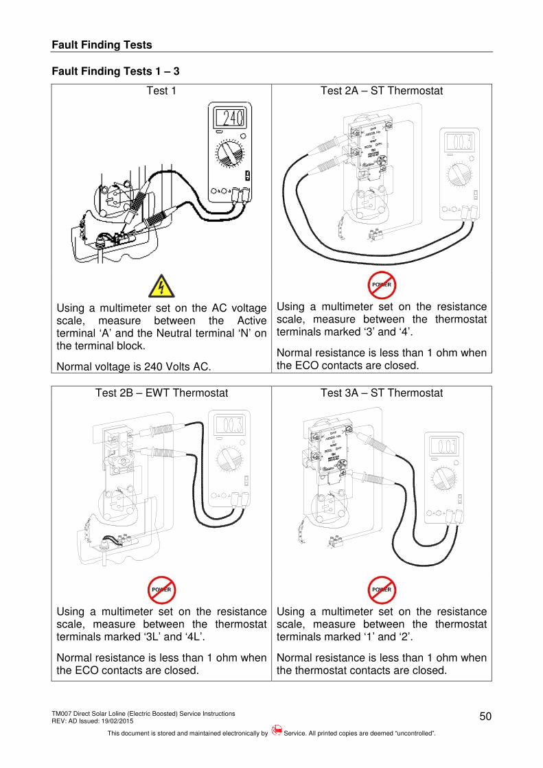
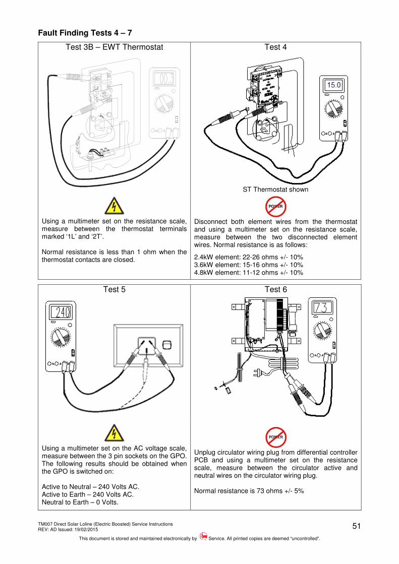
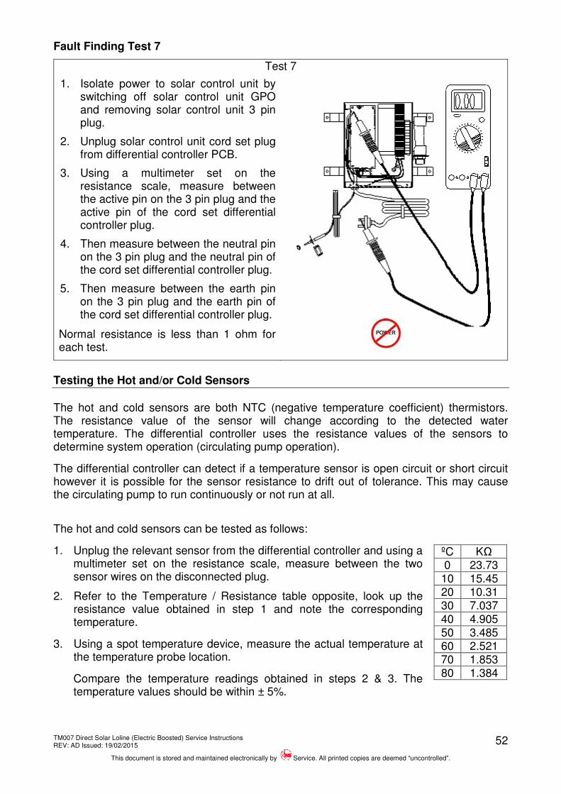
FAULT FINDING
Working on roofs should always be considered a hazardous activity, particularly early in the morning, late in the evening or after periods of rain. Safety precautions pertaining to working on roofs are outlined in the WorkCover Code of Practice “Safe work on roofs” Part 1 and 2 and in the Occupational Health and Safety Act 1983.
Water under pressure and at temperatures up to 150ºC may be present in the collector(s). Flush the collectors with cold water by opening the bleed valve. Isolate water supply and relieve pressure through a hot tap or the T&PR valve prior to opening the collector pipe work. Protective clothing should be worn to prevent scalding or burns.
If it is necessary to switch the power off to the solar control unit for a period of time and there is a risk of freezing, then it is necessary to drain the solar collectors and solar flow and return pipe work. Warranty does not cover damage caused by freeze conditions when the electrical circuit or electrical supply to the solar control unit is turned off or interrupted.
Common Faults
When a complaint is lodged about the performance of a hot water system there are a number of causes that should be checked and eliminated.
In an attempt to pinpoint the most likely cause it is important to discuss with the customer their reasons for the complaint, the duration of the problem, any change in circumstances or usage and recent weather conditions.
This information in conjunction with the following listed common complaints will assist you in locating the most likely cause. All procedures assume there is water flowing through the water heater.
Excessive hot water usage: The complaints of insufficient hot water and no hot water can on many occasions be attributed to hot water usage exceeding the capacity of the water heater to provide hot water.
When first attending a call of this nature it is essential to establish the probable hot water usage by querying the usage habits of the household and compare this with the potential delivery of the model water heater installed.
It can then be established if the usage is within or outside the capacity of the model. The areas to look at for excessive usage are:
1. Automatic washing machines.
2. Showers exceeding 12 litres/minute for mixed water and 5 minutes in duration.
3. Two or more showers operating at the same time.
4. Change of occupancy or number of persons increased.
5. High water pressure area (excessive T&PR discharge).
6. Plumbing leaks.
7. Thermostat temperature setting.
8. Crossed connection.
TM007 Direct Solar Loline (Electric Boosted) Service Instructions REV: AD Issued: 19/02/2015
This document is stored and maintained electronically by Service. All printed copies are deemed “uncontrolled”.
31
Discoloured water:
1. This may be the result of discoloured water entering from the cold water mains. Check if the cold water is also discoloured.
2. Brown coloured water will generally indicate that the anode has been depleted or the water heater is near the end of its useful life.
3. Milky coloured water is generally air in suspension and will disperse of its own accord. In very hard water areas where anode gassing occurs, milky water may be evident. The use of a blue anode should overcome this problem.
Water hammer: A water heater will not cause water hammer, however valves associated with the water heater may be the source of the problem i.e. cold water stopcock, non return valve, T&PR valve or relief valve.
Most water hammer problems are associated with plumbing, hot and cold, or appliances i.e. solenoid valves, ballcocks, loose pipes, sharp angles in pipe work, faulty or worn valve parts or neighbouring equipment.
High water pressure areas will have more complaints of this nature and the use of a pressure limiting valve (PLV) to reduce the household cold water pressure will usually solve most problems. Roof leaking: This complaint is usually made during or after wet weather and normally soon after commissioning a new water heater. The movement of persons on the roof during installation can crack roofing material if the load is borne on specific points or the roof material is brittle.
Replacement of damaged roof materials is essential. Use of a woven plastic roof sheet below the collectors will make water penetration more difficult in the future. It should also be established if water is penetrating around the pipe or sensor joints through the roof.
Moisture under the solar collector glass: Small amounts of condensate on the underside of the solar collector glass are not a sign of collector failure.
The condensation is formed from humid air condensing when the collector cools down. Because of high temperatures within the collector, ambient air is transferred in and out of the collector through drain holes. Note: The solar collector is not hermetically sealed.
Hot water plumbing leaks: If hot water has not been used for a period of time, feeling the temperature of the hot water line may give an indication of water flow if the pipe is warm.
The method of checking for plumbing leaks is:
1. Turn off the stopcock on the cold water supply to the water heater.
2. Open a hot tap to ensure the flow of water stops. This will confirm the stopcock is operating correctly.
3. Turn off the hot tap.
4. Turn on the stopcock to make up the water pressure in the cylinder, and then turn the stopcock off again.
5. Wait approximately 5 minutes then do either of the following:
a. With your ear close to the stopcock turn it on slightly and listen for any water passing. If there are no leaks, water should not pass.
b. Open a hot tap while listening for any pressure release. If there is a pressure release there will be no leaks in the plumbing system.
TM007 Direct Solar Loline (Electric Boosted) Service Instructions REV: AD Issued: 19/02/2015
This document is stored and maintained electronically by Service. All printed copies are deemed “uncontrolled”.
32
Mixing or crossed connections: If an automatic dishwasher, washing machine, flick mixer tap, tempering valve or thermostatic mixing valve is installed there is always the possibility that the cold water could mix with the hot water through a faulty or incorrectly installed valve.
This is referred to as a cross connection. The complaints of insufficient hot water, water too cold or excessive discharge from the T&PR valve may be attributed to a cross connection.
The method of checking for a cross connection is:
1. Turn off the stopcock on the cold water supply to the water heater.
2. Open a hot tap. If water flow is persistent and cold a cross connection exists. Test Equipment
A list of test equipment which will assist in conducting diagnostic procedures is provided below. This equipment is available from Rheem Service Spare Parts Department.
Fine probe adapter kit WH0020082 Probe to alligator clip kit WH0020084 Sensor LED test unit 890258
Differential Controller Operational & Fault Modes
Differential Controller 052113
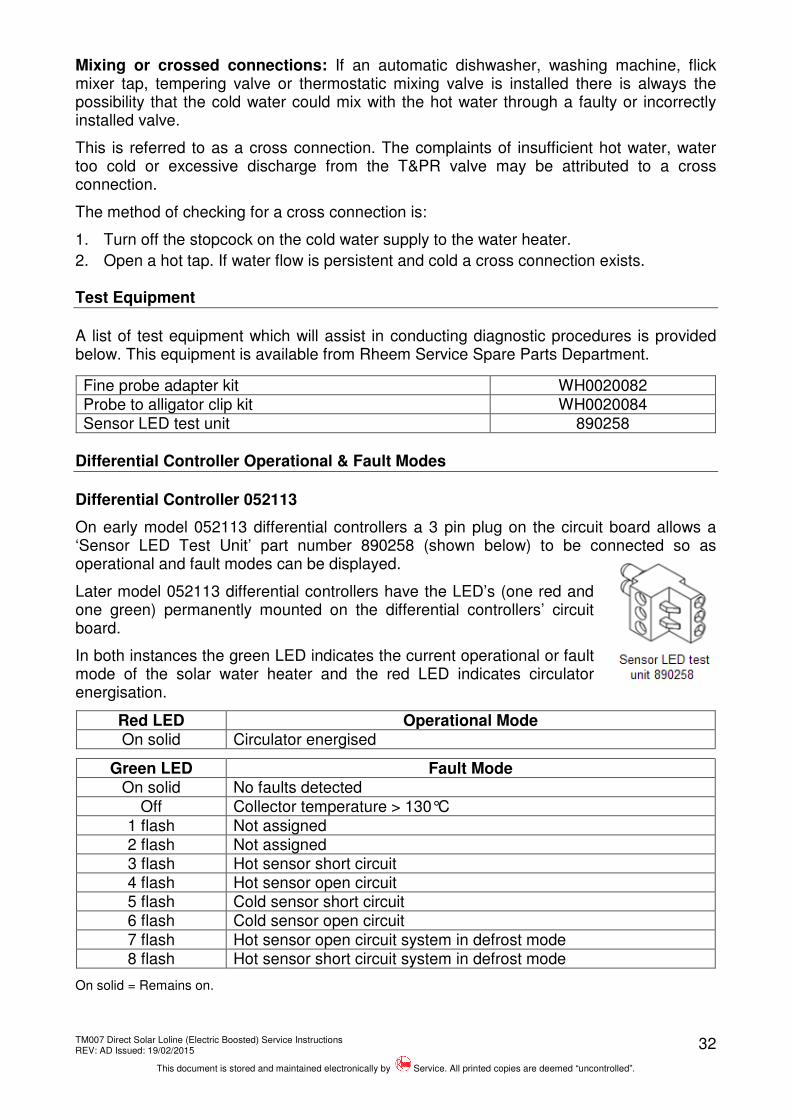
On early model 052113 differential controllers a 3 pin plug on the circuit board allows a ‘Sensor LED Test Unit’ part number 890258 (shown below) to be connected so as operational and fault modes can be displayed.
Later model 052113 differential controllers have the LED’s (one red and one green) permanently mounted on the differential controllers’ circuit board.
In both instances the green LED indicates the current operational or fault mode of the solar water heater and the red LED indicates circulator energisation.
Red LED Operational Mode On solid Circulator energised
Green LED Fault Mode On solid No faults detected
Off Collector temperature > 130°C
1 flash Not assigned 2 flash Not assigned
3 flash Hot sensor short circuit 4 flash Hot sensor open circuit 5 flash Cold sensor short circuit 6 flash Cold sensor open circuit
7 flash Hot sensor open circuit system in defrost mode 8 flash Hot sensor short circuit system in defrost mode
On solid = Remains on.
TM007 Direct Solar Loline (Electric Boosted) Service Instructions REV: AD Issued: 19/02/2015
This document is stored and maintained electronically by Service. All printed copies are deemed “uncontrolled”.
33
Differential Controller 052139
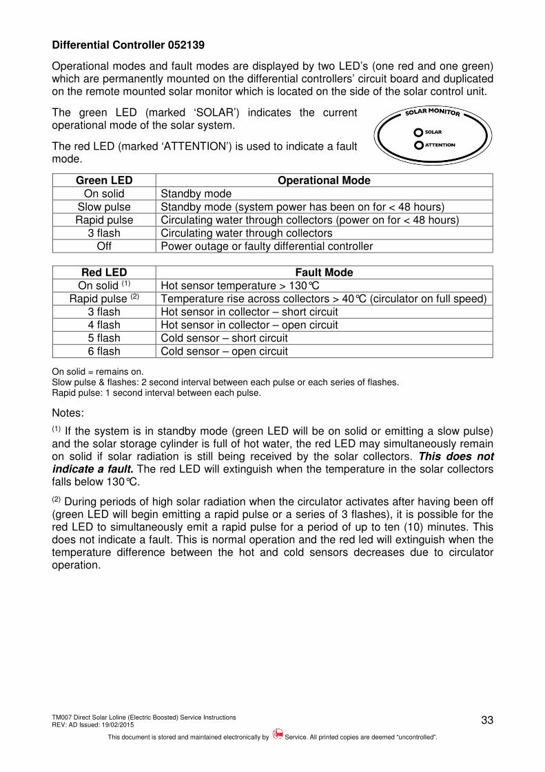
Operational modes and fault modes are displayed by two LED’s (one red and one green) which are permanently mounted on the differential controllers’ circuit board and duplicated on the remote mounted solar monitor which is located on the side of the solar control unit.
The green LED (marked ‘SOLAR’) indicates the current operational mode of the solar system.
The red LED (marked ‘ATTENTION’) is used to indicate a fault mode.
Green LED Operational Mode On solid Standby mode
Slow pulse Standby mode (system power has been on for < 48 hours) Rapid pulse Circulating water through collectors (power on for < 48 hours)
3 flash Circulating water through collectors Off Power outage or faulty differential controller
Red LED Fault Mode
On solid (1) Hot sensor temperature > 130°C Rapid pulse (2) Temperature rise across collectors > 40°C (circulator on full speed)
3 flash Hot sensor in collector – short circuit 4 flash Hot sensor in collector – open circuit 5 flash Cold sensor – short circuit 6 flash Cold sensor – open circuit
On solid = remains on. Slow pulse & flashes: 2 second interval between each pulse or each series of flashes. Rapid pulse: 1 second interval between each pulse.
Notes:
(1) If the system is in standby mode (green LED will be on solid or emitting a slow pulse) and the solar storage cylinder is full of hot water, the red LED may simultaneously remain on solid if solar radiation is still being received by the solar collectors. This does not indicate a fault. The red LED will extinguish when the temperature in the solar collectors falls below 130°C.
(2) During periods of high solar radiation when the circulator activates after having been off (green LED will begin emitting a rapid pulse or a series of 3 flashes), it is possible for the red LED to simultaneously emit a rapid pulse for a period of up to ten (10) minutes. This does not indicate a fault. This is normal operation and the red led will extinguish when the temperature difference between the hot and cold sensors decreases due to circulator operation.
TM007 Direct Solar Loline (Electric Boosted) Service Instructions REV: AD Issued: 19/02/2015
This document is stored and maintained electronically by Service. All printed copies are deemed “uncontrolled”.
34
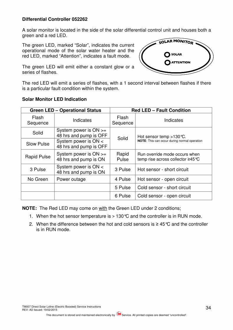
Differential Controller 052262 A solar monitor is located in the side of the solar differential control unit and houses both a green and a red LED.
The green LED, marked “Solar”, indicates the current operational mode of the solar water heater and the red LED, marked “Attention”, indicates a fault mode. The green LED will emit either a constant glow or a series of flashes. The red LED will emit a series of flashes, with a 1 second interval between flashes if there is a particular fault condition within the system. Solar Monitor LED Indication
Green LED – Operational Status Red LED – Fault Condition
Flash Sequence
Indicates Flash
Sequence Indicates
Solid System power is ON >= 48 hrs and pump is OFF
Solid Hot sensor temp >130°C. NOTE: This can occur during normal operation
Slow Pulse System power is ON < 48 hrs and pump is OFF
Rapid Pulse System power is ON >= 48 hrs and pump is ON
Rapid Pulse
Run override mode occurs when temp rise across collector ≥45°C
3 Pulse System power is ON < 48 hrs and pump is ON
3 Pulse Hot sensor - short circuit
No Green Power outage 4 Pulse Hot sensor - open circuit
5 Pulse Cold sensor - short circuit
6 Pulse Cold sensor - open circuit
NOTE: The Red LED may come on with the Green LED under 2 conditions;
1. When the hot sensor temperature is > 130°C and the controller is in RUN mode.
2. When the difference between the hot and cold sensors is ≥ 45°C and the controller is in RUN mode.
TM007 Direct Solar Loline (Electric Boosted) Service Instructions REV: AD Issued: 19/02/2015
This document is stored and maintained electronically by Service. All printed copies are deemed “uncontrolled”.
35
Fault Finding Charts
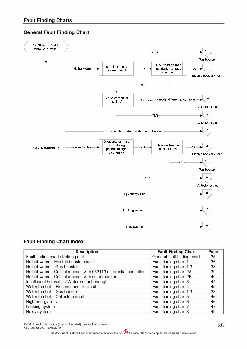
General Fault Finding Chart
Fault Finding Chart Index
Description Fault Finding Chart Page
Fault finding chart starting point General fault finding chart 35
No hot water – Electric booster circuit Fault finding chart 1 36
No hot water – Gas booster Fault finding chart 1.3 38
No hot water – Collector circuit with 052113 differential controller Fault finding chart 2A 39
No hot water – Collector circuit with solar monitor Fault finding chart 2B 40
Insufficient hot water / Water not hot enough Fault finding chart 3 44
Water too hot – Electric booster circuit Fault finding chart 4 45
Water too hot – Gas booster Fault finding chart 1.3 38
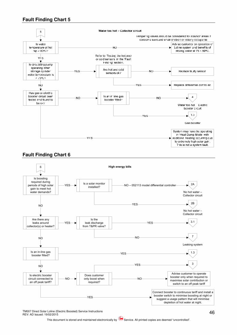
Water too hot – Collector circuit Fault finding chart 5 46
High energy bills Fault finding chart 6 46
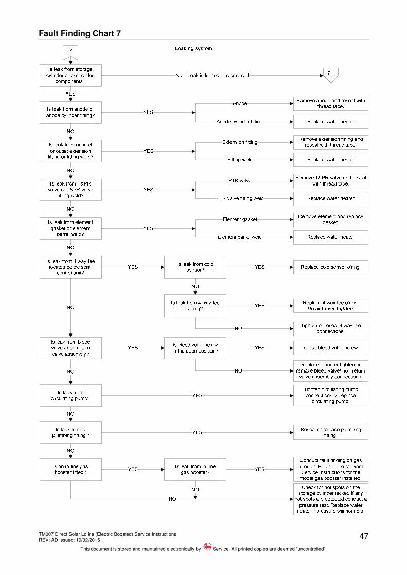
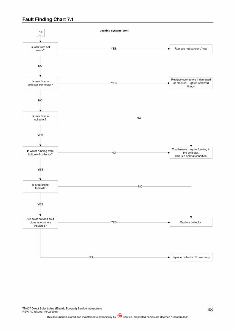
Leaking system Fault finding chart 7 47
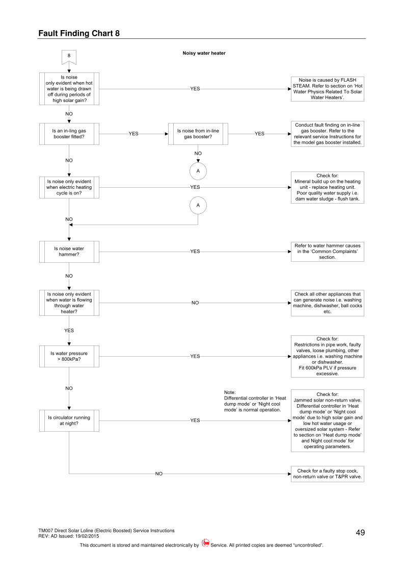
Noisy system Fault finding chart 8 49
TM007 Direct Solar Loline (Electric Boosted) Service Instructions REV: AD Issued: 19/02/2015
This document is stored and maintained electronically by Service. All printed copies are deemed “uncontrolled”.
36
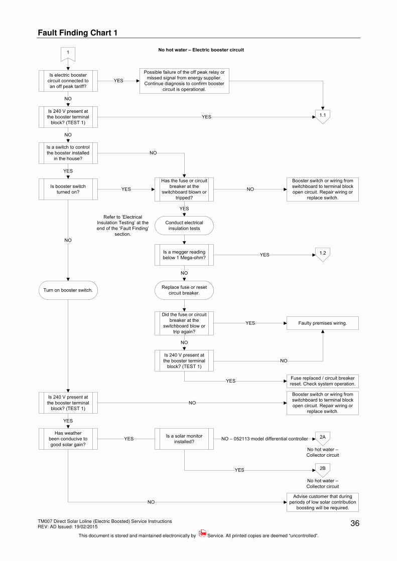
Fault Finding Chart 1
1
YES
NO
NO
YES
No hot water – Electric booster circuit
Is electric booster
circuit connected to
an off peak tariff?
Is 240 V present at
the booster terminal
block? (TEST 1)
Is a switch to control
the booster installed
in the house?
Possible failure of the off peak relay or
missed signal from energy supplier.
Continue diagnosis to confirm booster
circuit is operational.
1.1
NO
Is booster switch
turned on?
YES
Turn on booster switch.
NO
Is 240 V present at
the booster terminal
block? (TEST 1)
YES
Has weather
been conducive to
good solar gain?
YES
Advise customer that during
periods of low solar contribution
boosting will be required.
NO
YES
YES
NO
Has the fuse or circuit
breaker at the
switchboard blown or
tripped?
Booster switch or wiring from
switchboard to terminal block
open circuit. Repair wiring or
replace switch.
Conduct electrical
insulation tests
1.2
NO
YES
Booster switch or wiring from
switchboard to terminal block
open circuit. Repair wiring or
replace switch.
NO
Is a megger reading
below 1 Mega-ohm?
No hot water –
Collector circuit
Replace fuse or reset
circuit breaker.
Did the fuse or circuit
breaker at the
switchboard blow or
trip again?
NO
Faulty premises wiring.YES
Is 240 V present at
the booster terminal
block? (TEST 1)
NO
YESFuse replaced / circuit breaker
reset. Check system operation.
Refer to ‘Electrical
Insulation Testing’ at the
end of the ‘Fault Finding’
section.
2A
2B
NO – 052113 model differential controller
YES
No hot water –
Collector circuit
Is a solar monitor
installed?
TM007 Direct Solar Loline (Electric Boosted) Service Instructions REV: AD Issued: 19/02/2015
This document is stored and maintained electronically by Service. All printed copies are deemed “uncontrolled”.
37
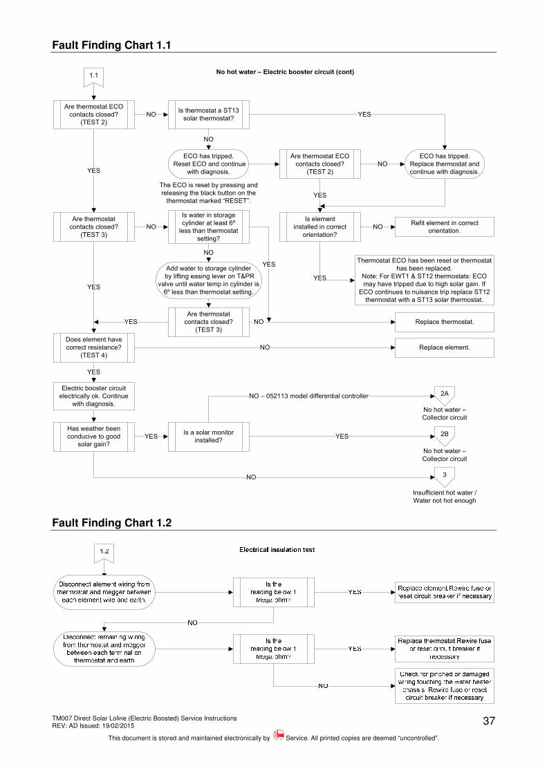
Fault Finding Chart 1.1
1.1
NO
YES
YES
NO
No hot water – Electric booster circuit (cont)
Are thermostat ECO
contacts closed?
(TEST 2)
Are thermostat
contacts closed?
(TEST 3)
Is water in storage
cylinder at least 6º
less than thermostat
setting?
YES
Replace thermostat.
Add water to storage cylinder
by lifting easing lever on T&PR
valve until water temp in cylinder is
6º less than thermostat setting.
NO
Are thermostat
contacts closed?
(TEST 3)
Does element have
correct resistance?
(TEST 4)
YES
YES
Has weather been
conducive to good
solar gain?
3NO
Replace element.NO
Insufficient hot water /
Water not hot enough
Electric booster circuit
electrically ok. Continue
with diagnosis.
ECO has tripped.
Reset ECO and continue
with diagnosis.
The ECO is reset by pressing and
releasing the black button on the
thermostat marked “RESET”.
Is element
installed in correct
orientation?
Refit element in correct
orientation.NO
Thermostat ECO has been reset or thermostat
has been replaced.
Note: For EWT1 & ST12 thermostats: ECO
may have tripped due to high solar gain. If
ECO continues to nuisance trip replace ST12
thermostat with a ST13 solar thermostat.
YES
NO
Are thermostat ECO
contacts closed?
(TEST 2)
YES
NO
ECO has tripped.
Replace thermostat and
continue with diagnosis.
Is thermostat a ST13
solar thermostat?YES
NO
No hot water –
Collector circuit
2A
2B
NO – 052113 model differential controller
YES
No hot water –
Collector circuit
Is a solar monitor
installed?YES
Fault Finding Chart 1.2
TM007 Direct Solar Loline (Electric Boosted) Service Instructions REV: AD Issued: 19/02/2015
This document is stored and maintained electronically by Service. All printed copies are deemed “uncontrolled”.
38
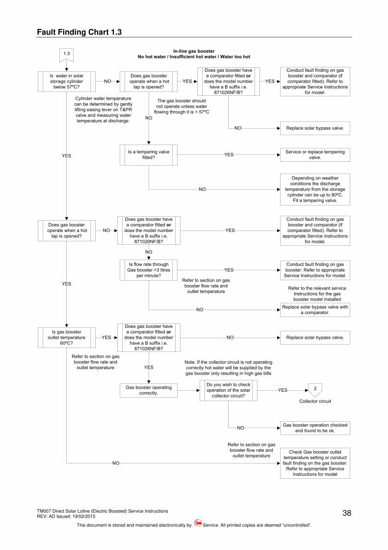
Fault Finding Chart 1.3
1.3
NO
In-line gas booster
No hot water / Insufficient hot water / Water too hot
Is water in solar
storage cylinder
below 57ºC?
Cylinder water temperature
can be determined by gently
lifting easing lever on T&PR
valve and measuring water
temperature at discharge.
Refer to section on gas
booster flow rate and
outlet temperature
Refer to section on gas
booster flow rate and
outlet temperature
Does gas booster
operate when a hot
tap is opened?
YES YES
NO Replace solar bypass valve.
Is a tempering valve
fitted?
NO
Service or replace tempering
valve.YES
Depending on weather
conditions the discharge
temperature from the storage
cylinder can be up to 80ºC.
Fit a tempering valve.
NO
Does gas booster
operate when a hot
tap is opened?
YES
Is flow rate through
Gas booster >3 litres
per minute?
NO
Does gas booster have
a comparator fitted or
does the model number
have a B suffix i.e.
871026NF/B?
NO
NO
YES
Replace solar bypass valve.
YES
Conduct fault finding on gas
booster and comparator (if
comparator fitted). Refer to
appropriate Service Instructions
for model.
Is gas booster
outlet temperature
60ºC?
YES
Does gas booster have
a comparator fitted or
does the model number
have a B suffix i.e.
871026NF/B?
YES
Check Gas booster outlet
temperature setting or conduct
fault finding on the gas booster.
Refer to appropriate Service
Instructions for model
NO
Does gas booster have
a comparator fitted or
does the model number
have a B suffix i.e.
871026NF/B?
Replace solar bypass valve with
a comparator.
YES
NO
Conduct fault finding on gas
booster and comparator (if
comparator fitted). Refer to
appropriate Service Instructions
for model.
Conduct fault finding on gas
booster. Refer to appropriate
Service Instructions for model.
The gas booster should
not operate unless water
flowing through it is < 57ºC
Do you wish to check
operation of the solar
collector circuit?
2YES
Gas booster operation checked
and found to be ok.NO
Gas booster operating
correctly.
Collector circuit
Note: If the collector circuit is not operating
correctly hot water will be supplied by the
gas booster only resulting in high gas bills
Refer to section on gas
booster flow rate and
outlet temperature
Refer to the relevant service
Instructions for the gas
booster model installed
TM007 Direct Solar Loline (Electric Boosted) Service Instructions REV: AD Issued: 19/02/2015
This document is stored and maintained electronically by Service. All printed copies are deemed “uncontrolled”.
39
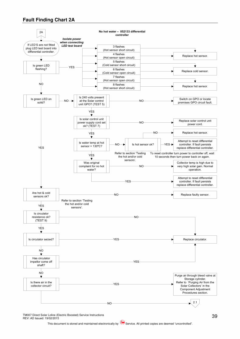
Fault Finding Chart 2A
2A No hot water – 052133 differential
controller
2.1
NO
If LED’S are not fitted
plug LED test board into
differential controller.
Isolate power
when connecting
LED test board
Is green LED
flashing?
3 flashes
(Hot sensor short circuit)
Replace hot sensor.4 flashes
(Hot sensor open circuit)
5 flashes
(Cold sensor short circuit)
Replace cold sensor.6 flashes
(Cold sensor open circuit)
7 flashes
(Hot sensor open circuit)
8 flashes
(Hot sensor short circuit)Replace hot sensor.
Is green LED on
solid?
NO
YES
Are hot & cold
sensors ok?
YES
Refer to section ‘Testing
the hot and/or cold
sensors’.
Replace faulty sensor.NO
Is circulator
resistance ok?
(TEST 9)
YES
Replace circulator.
NO
Is circulator seized?
YES
YES
Has circulator
impellor come off
shaft?
NO
YES
Is there air in the
collector circuit?
NOPurge air through bleed valve at
Storage cylinder.
Refer to ‘Purging Air from the
Solar Collectors’ in the
Component Adjustment
Procedures section.
YES
NO
NOIs water temp at hot
sensor > 130ºC?
Collector temp is high due to
very high solar gain. Normal
operation.
Was original
complaint for no hot
water?
YES
NO
NO
NO
Is 240 volts present
at the Solar control
unit GPO? (TEST 5)
Is solar control unit
power supply cord set
ok? (TEST 7)
YES
Replace solar control unit
power cord.
YES
Is hot sensor ok?
Attempt to reset differential
controller. If fault persists
replace differential controller.
YES
Attempt to reset differential
controller. If fault persists
replace differential controller.
Replace hot sensor.
YES
NO
To reset controller turn power to controller off, wait
10 seconds then turn power back on again.
Refer to section ‘Testing
the hot and/or cold
sensors’.
Switch on GPO or locate
premises GPO circuit fault.
TM007 Direct Solar Loline (Electric Boosted) Service Instructions REV: AD Issued: 19/02/2015
This document is stored and maintained electronically by Service. All printed copies are deemed “uncontrolled”.
40
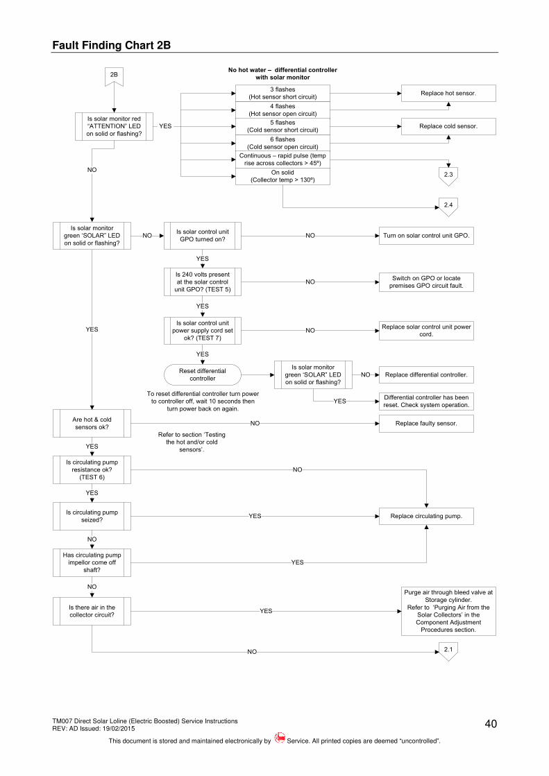
Fault Finding Chart 2B
NO
2B
NO
YES
Is solar control unit
power supply cord set
ok? (TEST 7)
Are hot & cold
sensors ok?
YES
Refer to section ‘Testing
the hot and/or cold
sensors’.
Replace faulty sensor.NO
Is circulating pump
resistance ok?
(TEST 6)
YES
Replace circulating pump.
NO
Is circulating pump
seized?
YES
YES
Has circulating pump
impellor come off
shaft?
NO
YES
Is solar monitor red
“ATTENTION” LED
on solid or flashing?
Is there air in the
collector circuit?YES
NO
NO
2.1
Reset differential
controllerReplace differential controller.
Differential controller has been
reset. Check system operation.
NO
YES
Is solar monitor
green ‘SOLAR” LED
on solid or flashing?
To reset differential controller turn power
to controller off, wait 10 seconds then
turn power back on again.
Is solar control unit
GPO turned on?Turn on solar control unit GPO.NO
Is 240 volts present
at the solar control
unit GPO? (TEST 5)
YES
Switch on GPO or locate
premises GPO circuit fault.
YES
Replace solar control unit power
cord.NO
Is solar monitor
green ‘SOLAR” LED
on solid or flashing?
NO
3 flashes
(Hot sensor short circuit)Replace hot sensor.
4 flashes
(Hot sensor open circuit)
5 flashes
(Cold sensor short circuit)Replace cold sensor.
6 flashes
(Cold sensor open circuit)
Continuous – rapid pulse (temp
rise across collectors > 45º)
YES
On solid
(Collector temp > 130º)2.3
2.4
No hot water – differential controller
with solar monitor
Purge air through bleed valve at
Storage cylinder.
Refer to ‘Purging Air from the
Solar Collectors’ in the
Component Adjustment
Procedures section.
TM007 Direct Solar Loline (Electric Boosted) Service Instructions REV: AD Issued: 19/02/2015
This document is stored and maintained electronically by Service. All printed copies are deemed “uncontrolled”.
41
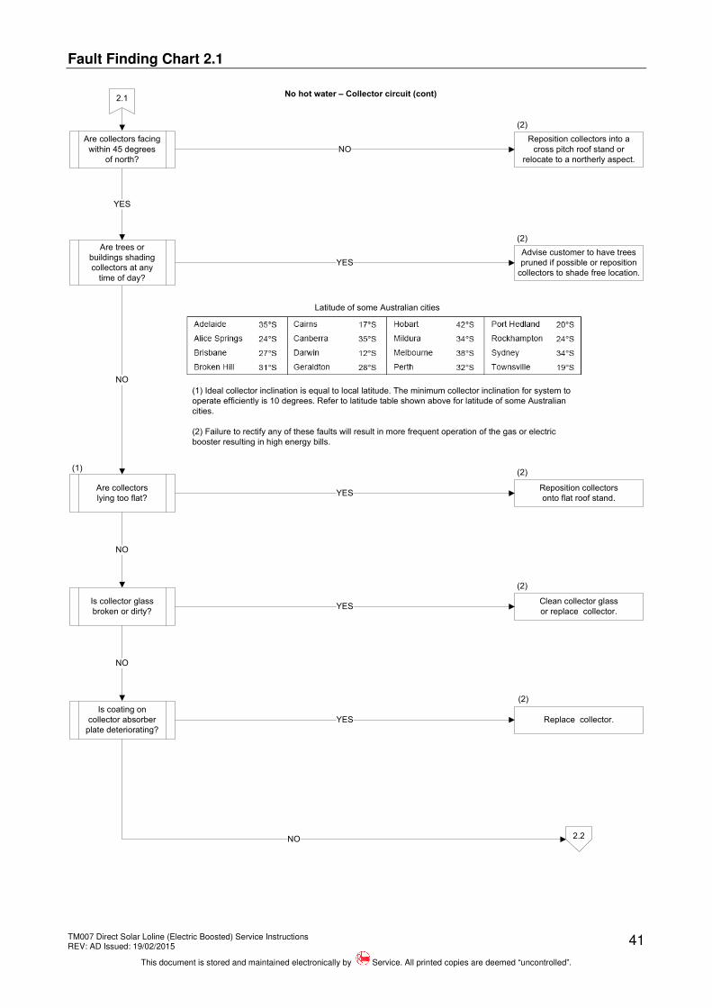
Fault Finding Chart 2.1
2.1
NO
YES
NO
YES
No hot water – Collector circuit (cont)
Are collectors facing
within 45 degrees
of north?
Are trees or
buildings shading
collectors at any
time of day?
Reposition collectors into a
cross pitch roof stand or
relocate to a northerly aspect.
Are collectors
lying too flat?
NO
2.2
Advise customer to have trees
pruned if possible or reposition
collectors to shade free location.
(1) Ideal collector inclination is equal to local latitude. The minimum collector inclination for system to
operate efficiently is 10 degrees. Refer to latitude table shown above for latitude of some Australian
cities.
(2) Failure to rectify any of these faults will result in more frequent operation of the gas or electric
booster resulting in high energy bills.
Reposition collectors
onto flat roof stand.YES
Is collector glass
broken or dirty?
Clean collector glass
or replace collector.YES
Is coating on
collector absorber
plate deteriorating?
NO
Replace collector.YES
NO
Latitude of some Australian cities
(1)
(2)
(2)
(2)
(2)
(2)
TM007 Direct Solar Loline (Electric Boosted) Service Instructions REV: AD Issued: 19/02/2015
This document is stored and maintained electronically by Service. All printed copies are deemed “uncontrolled”.
42
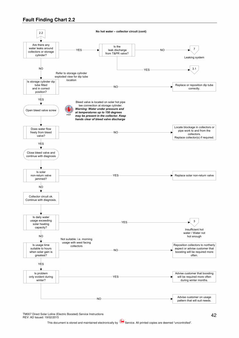
Fault Finding Chart 2.2
2.2
YES
NO
YES
NO
No hot water – collector circuit (cont)
Are there any
water leaks around
collectors or storage
cylinder?
Is storage cylinder dip
tube fitted
and in correct
position?
Open bleed valve screw
Does water flow
freely from bleed
valve?
YES
NO
Bleed valve is located on solar hot pipe
tee connection at storage cylinder.
Warning: Water under pressure and
at temperatures up to 150 degrees
may be present in the collector. Keep
hands clear of bleed valve discharge
NO
Is the
leak discharge
from T&PR valve?
NO
3.1YES
Replace or reposition dip tube
correctly.
Locate blockage in collectors or
pipe work to and from the
collectors.
Replace collector(s) if required.
Close bleed valve and
continue with diagnosis
Is solar
non-return valve
jammed?
Replace solar non-return valveYES
Is daily water
usage exceeding
solar heating
capacity?
NO
Is usage time
suitable to hours
when solar gain is
greatest?
3YES
NONot suitable: i.e. morning
usage with west facing
collectors Reposition collectors to northerly
aspect or advise customer that
boosting will be required more
often.
NO
Is problem
only evident during
winter?
YES
Advise customer that boosting
will be required more often
during winter months.
YES
Advise customer on usage
pattern that will suit needs.
Insufficient hot
water / Water not
hot enough
Collector circuit ok.
Continue with diagnosis.
7
Leaking system
Refer to storage cylinder
exploded view for dip tube
location
TM007 Direct Solar Loline (Electric Boosted) Service Instructions REV: AD Issued: 19/02/2015
This document is stored and maintained electronically by Service. All printed copies are deemed “uncontrolled”.
43
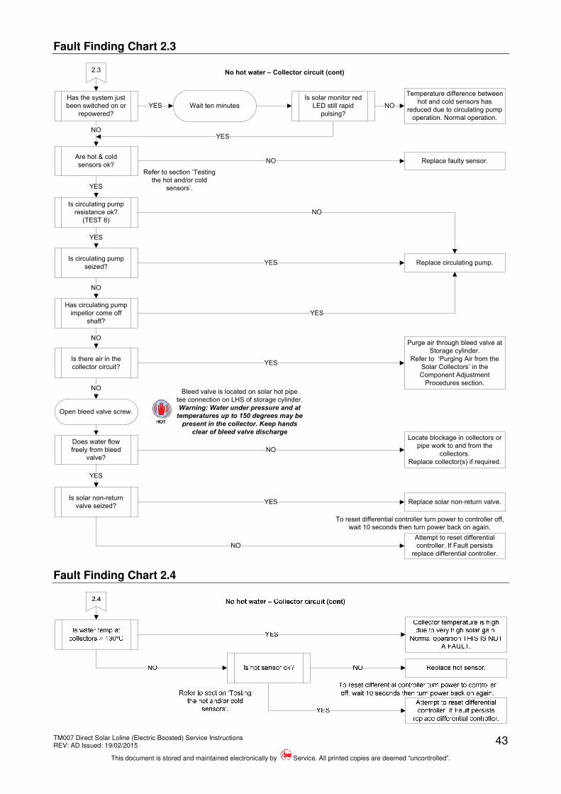
Fault Finding Chart 2.3
YES
Has the system just
been switched on or
repowered?
Temperature difference between
hot and cold sensors has
reduced due to circulating pump
operation. Normal operation.
YES
Wait ten minutes
Is solar monitor red
LED still rapid
pulsing?
NO
Are hot & cold
sensors ok?Refer to section ‘Testing
the hot and/or cold
sensors’.
Replace faulty sensor.NO
Is circulating pump
resistance ok?
(TEST 6)
YES
Replace circulating pump.
NO
Is circulating pump
seized?
YES
YES
Has circulating pump
impellor come off
shaft?
NO
YES
NO
YES
Bleed valve is located on solar hot pipe
tee connection on LHS of storage cylinder.
Warning: Water under pressure and at
temperatures up to 150 degrees may be
present in the collector. Keep hands
clear of bleed valve discharge
Open bleed valve screw.
Does water flow
freely from bleed
valve?
Locate blockage in collectors or
pipe work to and from the
collectors.
Replace collector(s) if required.
Is there air in the
collector circuit?
NO
NO
YES
Is solar non-return
valve seized?YES Replace solar non-return valve.
NO
To reset differential controller turn power to controller off,
wait 10 seconds then turn power back on again.
Attempt to reset differential
controller. If Fault persists
replace differential controller.
2.3 No hot water – Collector circuit (cont)
NO
Purge air through bleed valve at
Storage cylinder.
Refer to ‘Purging Air from the
Solar Collectors’ in the
Component Adjustment
Procedures section.
Fault Finding Chart 2.4
TM007 Direct Solar Loline (Electric Boosted) Service Instructions REV: AD Issued: 19/02/2015
This document is stored and maintained electronically by Service. All printed copies are deemed “uncontrolled”.
44
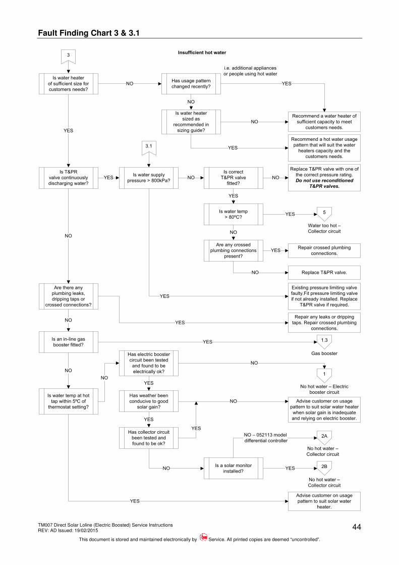
Fault Finding Chart 3 & 3.1
3
NO
YES
Insufficient hot water
Is water heater
of sufficient size for
customers needs?
Recommend a water heater of
sufficient capacity to meet
customers needs.
5
Repair crossed plumbing
connections.
YES
Is water heater
sized as
recommended in
sizing guide?
NO
NO
Recommend a hot water usage
pattern that will suit the water
heaters capacity and the
customers needs.
YES
Is T&PR
valve continuously
discharging water?
Is water supply
pressure > 800kPa?YES
Is correct
T&PR valve
fitted?
NO
3.1
Replace T&PR valve with one of
the correct pressure rating.
Do not use reconditioned
T&PR valves.
NO
Is water temp
> 80ºC?
YES
YES
Are any crossed
plumbing connections
present?
NO
Replace T&PR valve.
YES
NO
Existing pressure limiting valve
faulty.Fit pressure limiting valve
if not already installed. Replace
T&PR valve if required.
YES
Are there any
plumbing leaks,
dripping taps or
crossed connections?
NO
Repair any leaks or dripping
taps. Repair crossed plumbing
connections.
YES
Is water temp at hot
tap within 5ºC of
thermostat setting?
NO
1.3
Advise customer on usage
pattern to suit solar water
heater.
YES
Has usage pattern
changed recently?
i.e. additional appliances
or people using hot water
No hot water – Electric
booster circuit
Water too hot –
Collector circuit
Has electric booster
circuit been tested
and found to be
electrically ok?
YES
Advise customer on usage
pattern to suit solar water heater
when solar gain is inadequate
and relying on electric booster.
NO
NO
Has weather been
conducive to good
solar gain?
Has collector circuit
been tested and
found to be ok?
YES
No hot water –
Collector circuit
2A
2B
NO – 052113 model
differential controller
YES
No hot water –
Collector circuit
Is a solar monitor
installed?
YES
YES
1NO
Gas booster
Is an in-line gas
booster fitted?
NO
NO
TM007 Direct Solar Loline (Electric Boosted) Service Instructions REV: AD Issued: 19/02/2015
This document is stored and maintained electronically by Service. All printed copies are deemed “uncontrolled”.
45
Fault Finding Chart 4
TM007 Direct Solar Loline (Electric Boosted) Service Instructions REV: AD Issued: 19/02/2015
This document is stored and maintained electronically by Service. All printed copies are deemed “uncontrolled”.
46
Fault Finding Chart 5
Fault Finding Chart 6
6
YES
NO
NO
High energy bills
Is boosting
required during
periods of high solar
gain to meet hot
water demands?
Are there any
leaks around
collector(s) or heater?
3
YES
Is the
leak discharge
from T&PR valve?
YES 3.1
7
YES
NO
Is electric booster
circuit connected to
an off peak tariff?
Does customer
only boost when
required?
NO
Advise customer to operate
booster only when required to
maximise solar contribution or
switch to an off peak tariff
NO
Connect booster to continuous tariff and install a
booster switch to minimise boosting at night or
suggest a usage pattern that will minimise
depletion of hot water at night.
YES
Leaking system
No hot water –
Collector circuit
2A
2B
NO – 052113 model differential controller
YES
No hot water –
Collector circuit
Is a solar monitor
installed?
Is an in-line gas
booster fitted?
NO YES
1.3
TM007 Direct Solar Loline (Electric Boosted) Service Instructions REV: AD Issued: 19/02/2015
This document is stored and maintained electronically by Service. All printed copies are deemed “uncontrolled”.
47
Fault Finding Chart 7
TM007 Direct Solar Loline (Electric Boosted) Service Instructions REV: AD Issued: 19/02/2015
This document is stored and maintained electronically by Service. All printed copies are deemed “uncontrolled”.
48
Fault Finding Chart 7.1
7.1
NO
YESIs leak from hot
senor?
Is leak from a
collector?
Replace collector.
Condensate may be forming in
the collector.
This is a normal condition.
Replace connectors if damaged
or cracked. Tighten screwed
fittings.
NO
Is water running from
bottom of collector?
YES
NO
Is area prone
to frost?
YES
NO
Replace collector. No warranty.
Are solar hot and cold
pipes adequately
insulated?
YES
YES
NO
Is leak from a
collector connector?
Replace hot sensor o’ring.
YES
NO
Leaking system (cont)
TM007 Direct Solar Loline (Electric Boosted) Service Instructions REV: AD Issued: 19/02/2015
This document is stored and maintained electronically by Service. All printed copies are deemed “uncontrolled”.
49
Fault Finding Chart 8
8
YES
NO
Noisy water heater
Is noise
only evident when hot
water is being drawn
off during periods of
high solar gain?
Noise is caused by FLASH
STEAM. Refer to section on ‘Hot
Water Physics Related To Solar
Water Heaters’.
Check for:
Mineral build up on the heating
unit - replace heating unit.
Poor quality water supply i.e.
dam water sludge - flush tank.
YES
Is noise only evident
when electric heating
cycle is on?
Is noise only evident
when water is flowing
through water
heater?
Is noise water
hammer?
Is water pressure
> 800kPa?
Is circulator running
at night?
NO
NO
YES
NO
NO
YES
YES
NO
YES
Refer to water hammer causes
in the ‘Common Complaints’
section.
Check all other appliances that
can generate noise i.e. washing
machine, dishwasher, ball cocks
etc.
Check for:
Restrictions in pipe work, faulty
valves, loose plumbing, other
appliances i.e. washing machine
or dishwasher.
Fit 600kPa PLV if pressure
excessive.
Check for:
Jammed solar non-return valve.
Differential controller in ‘Heat
dump mode’ or ‘Night cool
mode’ due to high solar gain and
low hot water usage or
oversized solar system - Refer
to section on ‘Heat dump mode’
and Night cool mode’ for
operating parameters.
Check for a faulty stop cock,
non-return valve or T&PR valve.
Note:
Differential controller in ‘Heat
dump mode’ or ‘Night cool
mode’ is normal operation.
Is an in-ling gas
booster fitted?
Is noise from in-line
gas booster?
NO
YES
Conduct fault finding on in-line
gas booster. Refer to the
relevant service Instructions for
the model gas booster installed.
YES
NO
A
A
TM007 Direct Solar Loline (Electric Boosted) Service Instructions REV: AD Issued: 19/02/2015
This document is stored and maintained electronically by Service. All printed copies are deemed “uncontrolled”.
50
Fault Finding Tests
Fault Finding Tests 1 – 3
Test 1 Test 2A – ST Thermostat
Using a multimeter set on the AC voltage scale, measure between the Active terminal ‘A’ and the Neutral terminal ‘N’ on the terminal block.
Normal voltage is 240 Volts AC.
Using a multimeter set on the resistance scale, measure between the thermostat terminals marked ‘3’ and ‘4’.
Normal resistance is less than 1 ohm when the ECO contacts are closed.
Test 2B – EWT Thermostat Test 3A – ST Thermostat
Using a multimeter set on the resistance scale, measure between the thermostat terminals marked ‘3L’ and ‘4L’.
Normal resistance is less than 1 ohm when the ECO contacts are closed.
Using a multimeter set on the resistance scale, measure between the thermostat terminals marked ‘1’ and ‘2’.
Normal resistance is less than 1 ohm when the thermostat contacts are closed.
TM007 Direct Solar Loline (Electric Boosted) Service Instructions REV: AD Issued: 19/02/2015
This document is stored and maintained electronically by Service. All printed copies are deemed “uncontrolled”.
51
Fault Finding Tests 4 – 7
Test 3B – EWT Thermostat Test 4
ST Thermostat shown
Using a multimeter set on the resistance scale, measure between the thermostat terminals marked ‘1L’ and ‘2T’. Normal resistance is less than 1 ohm when the thermostat contacts are closed.
Disconnect both element wires from the thermostat and using a multimeter set on the resistance scale, measure between the two disconnected element wires. Normal resistance is as follows:
Using a multimeter set on the AC voltage scale, measure between the 3 pin sockets on the GPO. The following results should be obtained when the GPO is switched on: Active to Neutral – 240 Volts AC. Active to Earth – 240 Volts AC. Neutral to Earth – 0 Volts.
Unplug circulator wiring plug from differential controller PCB and using a multimeter set on the resistance scale, measure between the circulator active and neutral wires on the circulator wiring plug. Normal resistance is 73 ohms +/- 5%
TM007 Direct Solar Loline (Electric Boosted) Service Instructions REV: AD Issued: 19/02/2015
This document is stored and maintained electronically by Service. All printed copies are deemed “uncontrolled”.
52
Fault Finding Test 7
Test 7
1. Isolate power to solar control unit by switching off solar control unit GPO and removing solar control unit 3 pin plug.
2. Unplug solar control unit cord set plug from differential controller PCB.
3. Using a multimeter set on the resistance scale, measure between the active pin on the 3 pin plug and the active pin of the cord set differential controller plug.
4. Then measure between the neutral pin on the 3 pin plug and the neutral pin of the cord set differential controller plug.
5. Then measure between the earth pin on the 3 pin plug and the earth pin of the cord set differential controller plug.
Normal resistance is less than 1 ohm for each test.
Testing the Hot and/or Cold Sensors
The hot and cold sensors are both NTC (negative temperature coefficient) thermistors. The resistance value of the sensor will change according to the detected water temperature. The differential controller uses the resistance values of the sensors to determine system operation (circulating pump operation).
The differential controller can detect if a temperature sensor is open circuit or short circuit however it is possible for the sensor resistance to drift out of tolerance. This may cause the circulating pump to run continuously or not run at all.
The hot and cold sensors can be tested as follows:
1. Unplug the relevant sensor from the differential controller and using a multimeter set on the resistance scale, measure between the two sensor wires on the disconnected plug.
2. Refer to the Temperature / Resistance table opposite, look up the resistance value obtained in step 1 and note the corresponding temperature.
3. Using a spot temperature device, measure the actual temperature at the temperature probe location.
Compare the temperature readings obtained in steps 2 & 3. The temperature values should be within ± 5%.
TM007 Direct Solar Loline (Electric Boosted) Service Instructions REV: AD Issued: 19/02/2015
This document is stored and maintained electronically by Service. All printed copies are deemed “uncontrolled”.
53
ELECTRICAL INSULATION TESTING
There are three basic test procedures that should be carried out when the operation and function of a water heater’s electrical system is in doubt.
Personal Protective Equipment should be worn when conducting this procedure to reduce the risk of electric shock.
Do not Megger test the solar control unit. Megger testing the solar control unit will cause damage to the differential controller PCB.
To check insulation resistance of the electric booster Neutral circuit (reading not to be below 1 mega-ohm).
1. Isolate the power supply to the water heaters booster circuit by removing fuse or switching off circuit breaker. Confirm with a multi-meter between the Active and Neutral at the electric booster terminal block that voltage is not present.
2. Once satisfied, disconnect the power supply active and neutral wires from the terminal block.
3. Connect megger leads to the neutral of the water heater wiring and earth.
4. Operate megger on 500 VDC setting. A reading above 1 mega-ohm should be obtained.
5. If a reading below 1 mega-ohm is obtained, all component parts will need to be individually tested to locate the fault (refer to ‘Fault Finding Chart 1.2’ on page 37).
To check insulation resistance of the electric booster Active circuit (reading not to be below 1 mega-ohm).
6. Connect megger leads to the active of the water heater wiring and earth.
7. Operate megger on 500 VDC setting. A reading above 1 mega-ohm should be obtained.
8. If a reading below 1 mega-ohm is obtained, all component parts will need to be individually tested to locate the fault refer to ‘Fault Finding Chart 1.2’ on page 37).
To check “Continuity” of the electric booster electrical circuit.
9. Set megger to resistance scale or multimeter to x1 resistance scale and measure between the active and neutral wires on the water heater.
10. If a reading of less than 10 ohms or greater than 50 ohms is obtained, all electrical component parts will need to be individually tested to locate the fault (refer to ‘Test 4’ on page 51).
11. Reconnect power supply active cable to ‘A’ terminal and neutral cable to ‘N’ terminal at water heater terminal block.
12. Replace fuse or reset circuit breaker. Note: If continuing with diagnosis procedures do not replace fuse or reset circuit breaker.
TM007 Direct Solar Loline (Electric Boosted) Service Instructions REV: AD Issued: 19/02/2015
This document is stored and maintained electronically by Service. All printed copies are deemed “uncontrolled”.
54
COMPONENT ADJUSTMENT PROCEDURES
Purging Air from the Solar Collectors
An air eliminator is not fitted to the sequential freeze collector system. Upon completion of any repairs to the solar collectors, circulating pump, pipe work to and from the collectors or recommissioning if the cylinder has been drained, it will be necessary to purge any air from the collector circuit.
The following procedure should be performed in the morning, within three hours of sunrise, when the water temperature inside the solar collectors is lowest.
To purge air from the collector circuit:
1. Ensure solar storage cylinder is full of water and all premises hot taps are turned off.
2. Using a flat bladed screwdriver, rotate the bleed valve screw to the open position. The bleed valve is located on the solar hot water inlet (from collector) of the solar storage cylinder. Refer to diagram shown opposite.
3. Mains pressure will force water to flow from the solar storage cylinder, through the pipe work and solar collectors, expelling any trapped air from the collector circuit through the bleed valve. This is evidenced by water and air spurting from the drain line connected to the bleed valve.
Water under pressure and up to 150ºC may be expelled through the bleed valve during the purging process; keep hands and face well clear and wear protective clothing to prevent scalding or burns.
4. Using a flat bladed screwdriver, close bleed valve when all air has been purged by rotating bleed valve. Note: when air is purged water will run freely without spluttering
Electric Booster Thermostat Adjustment
The electric booster thermostat setting can be set by a qualified person to a minimum of 60°C and a maximum of 70°C (the booster thermostat has a factory setting of 70°C).
To adjust the booster thermostat:
Personal Protective Equipment should be worn when conducting step 3 of this procedure to reduce the risk of electric shock.
1. Isolate power to electric booster circuit by switching off the circuit breaker or isolator marked “Hot Water” or “Water Heater” at the switchboard.
2. Remove 2 screws retaining electric booster access cover and remove cover.
3. Confirm with a multi-meter between the Active and Neutral at the electric booster terminal block that voltage is not present.
4. Turn thermostat temperature adjustment dial clockwise to increase temperature setting or anticlockwise to decrease temperature setting.
5. Replace access cover.
6. Restore the power supply to the water heater.
TM007 Direct Solar Loline (Electric Boosted) Service Instructions REV: AD Issued: 19/02/2015
This document is stored and maintained electronically by Service. All printed copies are deemed “uncontrolled”.
55
Checking Gas Booster Flow Rate & Outlet Temperature
Refer to the relevant Service Instructions for the gas booster model installed COMPONENT REPLACEMENT PROCEDURES
Draining the Solar Storage Cylinder (Procedure 1)
Elevated temperatures may be present during the draining process. Personal Protective Equipment should be worn to prevent the risk of scalding.
Personal Protective Equipment should be worn when conducting step 4 of this procedure to reduce the risk of electric shock.
1. Isolate power to electric booster circuit by switching off the circuit breaker or isolator marked “Hot Water” or “Water Heater” at the switchboard.
2. Isolate power to solar control unit by switching off solar control unit GPO and removing solar control unit 3 pin plug.
3. Remove two screws retaining electric booster access cover and remove cover.
4. Confirm with a multi-meter between the Active and Neutral at the electric booster terminal block that voltage is not present.
5. Isolate the water supply to the water heater.
6. Relieve pressure from the water heater through the T&PR valve or a hot tap.
7. Disconnect the cold water supply pipe to the storage cylinder.
8. Fit a drain hose to the storage cylinders cold water connection and run the other end to a drain or safe location.
9. Open the T&PR valve to allow air into the system. Removing or Replacing an SCT/SBT Series Solar Collector (Procedure 2)
Water under pressure and at temperatures up to 150ºC may be present in the collector/s. Isolate water supply and relieve pressure through a hot tap or the temperature and pressure relief valve prior to opening the collector pipe work. Protective clothing should be worn to prevent scalding or burns.
1. Isolate power to electric booster circuit by switching off the circuit breaker or isolator marked “Hot Water” or “Water Heater” at the switchboard.
2. Isolate power to solar control unit by switching off solar control unit GPO and removing solar control unit 3 pin plug.
3. Isolate the water supply to the water heater.
4. Relieve pressure from the water heater through T&PR valve or a hot tap.
5. Disconnect the hot and cold pipes to the collectors at the water heater and cap the outlets to prevent the cylinder from draining. The collectors will now drain down.
6. Remove the retaining clip/s and spring clip/s from the collector connectors and end caps. The hot or cold pipe and end cap can now be disconnected from the collector by pulling the connector off the collector pipe.
TM007 Direct Solar Loline (Electric Boosted) Service Instructions REV: AD Issued: 19/02/2015
This document is stored and maintained electronically by Service. All printed copies are deemed “uncontrolled”.
56
7. Remove the retaining clip/s and spring clips from the inter-connectors at the top and bottom of the collector. Do not stand on the collectors.
8. Remove the screws retaining the collector to the angle bracket, disconnect the retaining strap at the top of the collector, slide the collector out and remove to ground level.
9. Reassemble in reverse order of above.
10. Once reassembly is complete, restore the water supply and check for leaks.
11. Open all hot water taps in premises including shower(s).
12. Close each hot water tap after all air is purged (when air is purged, water will run freely without air bubbles or spluttering).
13. Purge the collector circuit of air (refer to ‘Purging Air from the Solar Collectors’ on page 54). Note: Air trapped in the system can prevent solar gain from occurring and cause the system to operate on the electric booster only.
14. Restore the power supplies to the electric booster and solar control unit.
Removing or Replacing an NPT / HBT / TBT / LCS Solar Collector (Procedure 3)
Water under pressure and at temperatures up to 150ºC may be present in the collector/s. Isolate water supply and relieve pressure through a hot tap or the temperature and pressure relief valve prior to opening the collector pipe work. Protective clothing should be worn to prevent scalding or burns.
1. Isolate power to electric booster circuit by switching off the circuit breaker or isolator marked “Hot Water” or “Water Heater” at the switchboard.
2. Isolate power to solar control unit by switching off solar control unit GPO and removing solar control unit 3 pin plug.
3. Isolate the water supply to the water heater.
4. Relieve pressure from the water heater through the T&PR valve or a hot tap.
5. Disconnect the hot and cold pipes to the collectors at the water heater and cap the water heater fittings to prevent the cylinder from draining. The collectors will now drain down.
6. Depending on which collector requires replacement disconnect the hot or cold pipe from the collector fitting.
7. Unscrew the hot or cold collector adapter fitting from the collector.
8. Undo the collector unions at the top and bottom of the collector. Do not stand on the collector.
9. Remove the bolts from the clamps retaining the collector to the angle bracket and slide the collector out and remove to ground level.
10. Reassemble in reverse order of above.
11. Once reassembly is complete, restore the water supply and check for leaks.
12. Open all hot water taps in premises including shower(s).
13. Close each hot water tap after all air is purged (when air is purged, water will run freely without air bubbles or spluttering).
14. Purge the collector circuit of air (refer to ‘Purging Air from the Solar Collectors’ on page 54). Note: Air trapped in the system can prevent solar gain from occurring and cause the system to operate on the electric booster only.
15. Restore the power supplies to the electric booster and solar control unit.
TM007 Direct Solar Loline (Electric Boosted) Service Instructions REV: AD Issued: 19/02/2015
This document is stored and maintained electronically by Service. All printed copies are deemed “uncontrolled”.
57
Removing or Replacing a Titan or Australis Solar Collector (Procedure 4)
Water under pressure and at temperatures up to 150ºC may be present in the collector/s. Isolate water supply and relieve pressure through a hot tap or the temperature and pressure relief valve prior to opening the collector pipe work. Protective clothing should be worn to prevent scalding or burns.
1. Isolate power to electric booster circuit by switching off the circuit breaker or isolator marked “Hot Water” or “Water Heater” at the switchboard.
2. Isolate power to solar control unit by switching off solar control unit GPO and removing solar control unit 3 pin plug.
3. Isolate the water supply to the water heater.
4. Relieve pressure from the water heater through the T&PR valve or a hot tap.
5. Disconnect the hot and cold pipes to the collectors at the water heater and cap the water heater fittings to prevent the cylinder from draining. The collectors will now drain down.
6. Depending on which collector requires replacement disconnect the hot or cold pipe from the collector fitting.
7. Unscrew the hot or cold collector adapter fitting from the collector.
8. Undo the collector unions at the top and bottom of the collector. Do not stand on the collector.
9. Remove the screws retaining the collector to the top and bottom collector angles and slide the collector out and remove to ground level.
10. Reassemble in reverse order of above.
11. Once reassembly is complete, restore the water supply and check for leaks.
12. Open all hot water taps in premises including shower(s).
13. Close each hot water tap after all air is purged (when air is purged, water will run freely without air bubbles or spluttering).
14. Purge the collector circuit of air (refer to ‘Purging Air from the Solar Collectors’ on page 54). Note: Air trapped in the system can prevent solar gain from occurring and cause the system to operate on the electric booster only.
15. Restore the power supplies to the electric booster and solar control unit. Differential Controller PCB (Procedure 5)
1. Isolate power to solar control unit by switching off solar control unit GPO and removing solar control unit 3 pin plug.
2. Remove 2 screws retaining solar control unit access cover and remove cover.
3. Using a pair of long nose pliers, gently release the 4 clips retaining the differential controller PCB and remove PCB.
4. Mark and unplug circulating pump wiring from PCB.
5. Mark and unplug power supply wiring from PCB.
6. Mark and unplug hot and cold sensor wiring from PCB.
7. Reassemble in reverse order of above ensuring all wiring plugs are connected correctly.
8. Restore power to solar control unit by plugging 3 pin plug into GPO and switching on GPO.
TM007 Direct Solar Loline (Electric Boosted) Service Instructions REV: AD Issued: 19/02/2015
This document is stored and maintained electronically by Service. All printed copies are deemed “uncontrolled”.
58
Cold Sensor (Procedure 6)
Elevated temperatures may be present. Personal Protective Equipment should be worn to prevent the risk of scalding.
1. Isolate power to solar control unit by switching off solar control unit GPO and removing solar control unit 3 pin plug.
2. Isolate the water supply to the water heater.
3. Relieve pressure from the water heater through the T&PR valve or a hot tap.
4. Remove 2 screws retaining solar control unit access cover and remove cover.
5. Using a pair of long nose pliers, gently release the 4 clips retaining the differential controller PCB and remove PCB.
6. Undo gland nut (located underneath solar control unit) retaining cold sensor wiring.
7. Unplug cold sensor wiring from PCB and pull wiring out of gland.
8. Feed replacement cold sensor wiring up through gland and plug into PCB.
9. Tighten gland nut securely and push PCB back onto clips until PCB locks on clips.
10. Refit solar control unit cover.
11. Remove spring clip retaining cold sensor in ‘T’ piece, and remove cold sensor.
12. Fit replacement sensor into ‘T’ piece and secure with spring clip. Ensure clip retains the locating washer.
13. Restore water supply and check for leaks at cold sensor.
14. Restore power to solar control unit by plugging 3 pin plug into GPO and switching on GPO.
Hot Sensor (Procedure 7)
Warning: The collectors may be at stagnation temperature, water under pressure and at temperatures up to 150ºC may be present. Protective clothing should be worn to prevent burns or scalds.
1. Isolate power to solar control unit by switching off solar control unit GPO and removing solar control unit 3 pin plug.
2. Isolate the water supply to the water heater.
3. Relieve pressure from the water heater through the T&PR valve or a hot tap.
4. Remove spring clip retaining hot sensor in connector and remove hot sensor.
5. Fit replacement sensor into connector and secure with spring clip. Ensure clip retains the locating washer.
6. Cut existing sensor wiring and connect to replacement sensor. Ideally this connection should be made in the roof space. Note: If the connection is made on the roof, ensure the connection is water and UV proof.
7. Restore water supply and check for leaks at hot sensor.
8. Purge the collector circuit of air (refer to ‘Purging Air from the Solar Collectors’ on page 54). Note: Air trapped in the system can prevent solar gain from occurring and cause the system to operate on the electric booster only.
9. Restore power to solar control unit by plugging 3 pin plug into GPO and switching on GPO.
TM007 Direct Solar Loline (Electric Boosted) Service Instructions REV: AD Issued: 19/02/2015
This document is stored and maintained electronically by Service. All printed copies are deemed “uncontrolled”.
59
Anode (Procedure 8)
Elevated temperatures may be present. Personal Protective Equipment should be worn to prevent the risk of scalding.
1. Isolate power to electric booster circuit by switching off the circuit breaker or isolator marked “Hot Water” or “Water Heater” at the switchboard.
2. Isolate power to solar control unit by switching off solar control unit GPO and removing solar control unit 3 pin plug.
3. Isolate the water supply to the water heater.
4. Relieve pressure from the water heater through the T&PR valve or a hot tap.
5. Remove anode cap.
6. Using a tube or socket spanner remove the anode (32 mm spanner for 3/4” anode and 36 mm spanner for 1” anode).
7. Apply thread sealing tape to replacement anode, refit and tighten.
8. Restore water supply and check for leaks at anode.
9. Refit anode cap.
10. Purge air from the system through hot taps.
11. Restore the power supplies to the electric booster and solar control unit Solar Control Unit Cord Set (Procedure 9)
1. Isolate power to solar control unit by switching off solar control unit GPO and removing solar control unit 3 pin plug.
2. Remove 2 screws retaining solar control unit access cover and remove cover.
3. Remove cord anchor (located underneath solar control unit) retaining cord set.
4. Using a pair of long nose pliers, gently release the 4 clips retaining the differential controller PCB and remove PCB.
5. Unplug cord set from PCB.
6. Feed replacement cord set up through the opening in the control box and plug into PCB.
7. Fit cord anchor to replacement cord set and insert anchor securely into solar control unit box.
8. Push PCB back onto clips until PCB locks on clips.
9. Refit solar control unit access cover.
10. Restore power to solar control unit by plugging 3 pin plug into GPO and switching on GPO.
TM007 Direct Solar Loline (Electric Boosted) Service Instructions REV: AD Issued: 19/02/2015
This document is stored and maintained electronically by Service. All printed copies are deemed “uncontrolled”.
60
Circulating Pump (Procedure 10)
Warning: The collectors may be at stagnation temperature, water under pressure and at temperatures up to 150ºC may be present. Protective clothing should be worn to prevent burns or scalds.
1. Using a flat bladed screwdriver, rotate the bleed valve screw to the open position and purge water through the collectors to dissipate excess temperature. The bleed valve is located on the solar hot water inlet (from collector) of the solar storage cylinder (labelled “Connection for Solar Return Pipe). Refer to diagram in the ‘Purging Air from the Solar Collectors’ section on page 54.
2. Close bleed valve once excess temperature is removed.
3. Isolate power to electric booster circuit by switching off the circuit breaker or isolator marked “Hot Water” or “Water Heater” at the switchboard.
4. Isolate power to solar control unit by switching off solar control unit GPO and removing solar control unit 3 pin plug.
5. Isolate the water supply to the water heater.
6. Relieve pressure from the water heater through the T&PR valve or a hot tap.
7. Close T&PR valve or hot tap.
8. Remove 2 screws retaining solar control unit access cover and remove cover.
9. Using a pair of long nose pliers, gently release the 4 clips retaining the differential controller PCB and remove PCB.
10. Unplug pump wiring from PCB.
11. Undo large brass nut retaining pump motor to pump body and remove pump motor.
Warning: Extremely hot water may be present in the pump; protective clothing should be worn to prevent scalds or burns.
12. Remove Philips head screw from pump head and unclip the top cover.
13. Loosen cable entry gland, disconnect wiring from pump motor and remove motor.
14. Reconnect wiring to replacement pump.
15. Reassemble in reverse order of above. Note: The pump body rarely requires replacing. The new body will only need to be replaced if the existing unit is damaged.
16. Restore water supply and check for leaks at pump.
17. Purge the collector circuit of air (refer to ‘Purging Air from the Solar Collectors’ on page 54). Note: Air trapped in the system can prevent solar gain from occurring and cause the system to operate on the electric booster only.
18. Purge air from the system through hot taps.
19. Refit solar control unit cover.
20. Restore the power supplies to the electric booster and solar control unit.
TM007 Direct Solar Loline (Electric Boosted) Service Instructions REV: AD Issued: 19/02/2015
This document is stored and maintained electronically by Service. All printed copies are deemed “uncontrolled”.
61
Thermostat (Procedure 11)
Elevated temperatures may be present. Personal Protective Equipment should be worn to prevent the risk of scalding.
Personal Protective Equipment should be worn when conducting step 3 of this procedure to reduce the risk of electric shock.
1. Isolate power to electric booster circuit by switching off the circuit breaker or isolator marked “Hot Water” or “Water Heater” at the switchboard.
2. Remove two screws retaining electric booster access cover and remove cover.
3. Confirm with a multi-meter between the Active and Neutral at the electric booster terminal block that voltage is not present.
4. Mark and disconnect thermostat wiring.
5. Note thermostat setting and slide thermostat out from under retaining clamp.
6. Remove any scale from cylinder surface.
7. Fit replacement thermostat under clamp and set temperature noted in step 4 (factory setting is 60ºC).
8. Reconnect wiring as per the wiring diagram located on the rear of the booster access cover.
9. Refit booster access cover.
10. Restore the power supply to the electric booster. Element (Procedure 12)
Elevated temperatures may be present during element removal process. Personal Protective Equipment should be worn to prevent the risk of scalding.
When a fault or leak is traced to the electric booster element, the storage cylinder should be drained to prevent damage to flooring or floor coverings by accidental flooding.
1. Drain the water heater (refer to procedure 1).
2. When the water heater is drained, undo the four element screws, removing thermostat clamp first.
3. Withdraw the element. Care must be taken to ensure the loop of the element does not catch in the cylinder opening and open out inside the cylinder.
NOTE: Do not cut off the element and leave a portion inside the cylinder.
4. Clean around cylinder fitting, fit a new gasket to the new element and slide the element into the cylinder taking care that it is in the correct orientation. Refer to element flange for orientation directions. Note: Never reuse old element gaskets.
5. Replace screws and thermostat clamp and tighten. Note: The element retaining screws are tightened only until the return edge bottoms on the cylinder flange – do not over tighten.
TM007 Direct Solar Loline (Electric Boosted) Service Instructions REV: AD Issued: 19/02/2015
This document is stored and maintained electronically by Service. All printed copies are deemed “uncontrolled”.
62
6. The earthing of the internal storage cylinder relies on a good electrical contact between the metal surround of the element flange and the cylinder barrel flange.
An earth continuity test should be performed whenever an element or element gasket is replaced, adjusted or serviced in any way. This continuity test is performed between the heaters internal storage cylinder and the main earth terminal of the water heater with a resulting reading of not more than 0.5 ohms as required by AS/NZS 3000 6.3.3.2.
7. Restore water supply and fill the storage cylinder. Release air by gently lifting the easing lever on the T&PR valve until water runs from the drain or opened hot taps.
8. Check for water leaks around the element flange.
9. Conduct an electrical insulation test (refer to ‘Electrical Insulation Testing’ on page 53).
10. Replace booster access cover.
11. Restore the power supply to the electric booster.
TM007 Direct Solar Loline (Electric Boosted) Service Instructions REV: AD Issued: 19/02/2015
This document is stored and maintained electronically by Service. All printed copies are deemed “uncontrolled”.
The superseded SCT/SBT series collectors, when in use, utilised a unique method for connecting the collectors together and for coupling the hot and cold pipes to the collector.
The collector header pipes have 3 slots machined into the pipe end to locate 2 o-rings and a stainless steel retaining clip.
A connector or end cap manufactured from PPS is then slipped over the o-rings and retained by a stainless steel spring clip.
The spring clips are secured closed via a retaining clip placed around the legs. An adapter is fitted into the connector to allow connection of the hot and cold pipes via a ½” nut and olive.
Note: PPS connectors should be replaced with brass connectors on systems experiencing continual problems with leaking PPS connectors i.e. installations in areas prone to severe temperature fluctuations. To convert PPS connectors to brass connectors refer to ‘Conversion Procedure – PPS to Brass Connectors’ on page 64.
Inter-Connector Connector with sensor well
End Cap Cold Connector
TM007 Direct Solar Loline (Electric Boosted) Service Instructions REV: AD Issued: 19/02/2015
This document is stored and maintained electronically by Service. All printed copies are deemed “uncontrolled”.
PPS connectors should be replaced with brass connectors on installations experiencing continual problems with leaking PPS connectors i.e. installations in areas prone to severe temperature fluctuations.
Brass connectors utilize the same new method as PPS connectors for connecting the collectors together and for coupling the hot and cold pipes to the collector.
The collector header pipes have 3 slots machined into the pipe end to locate 2 o-rings and stainless steel retaining clip.
A connector or end cap manufactured from brass is then slipped over the o-rings and retained by a stainless steel spring clip.
The spring clips are secured closed via a retaining clip placed around the legs. An adapter is fitted into the connector to allow connection of the hot and cold pipes via a ½” nut and olive.
Inter-Connector Connector with sensor well
End Cap Cold Connector
Conversion Procedure – PPS Connectors to Brass Connectors
Brass connectors are supplied in kit form with all the necessary components required to replace the corresponding PPS connector. Available kits are as follows:
Connector PPS Kit Part Number Brass Kit Part Number Collector inter-connector 195701 195701B Hot connector 195702 195702B End cap 195703 195703B Cold connector 195704 195704B
TM007 Direct Solar Loline (Electric Boosted) Service Instructions REV: AD Issued: 19/02/2015
This document is stored and maintained electronically by Service. All printed copies are deemed “uncontrolled”.
65
The contents of each kit are as follows:
Kit Description Part Number Quantity
195701B Inter-connector
Brass adaptor 088126 2
Spring clip 088008 2
Sealing washer 087049 2
Brass connector 088127 1
195702B Hot connector
Brass adaptor 088126 1
Spring clip 088008 1
Sealing washer 087049 1
Temp send brass connector 063605 1
Sensor nipple 088062 1
O-ring 087026 1
195703B End cap
Brass adaptor 088126 1
Spring clip 088008 1
Sealing washer 087049 1
Blanking disk 330606 1
Gland nut 330600 1
195704B Cold connector
Brass adaptor 088126 1
Spring clip 088008 1
Sealing washer 087049 1
Brass connector - cold 063603 1
Working on roofs should always be considered a hazardous activity, particularly early in the morning, late in the evening or after periods of rain. Safety precautions pertaining to working on roofs are outlined in the WorkCover Code of Practice “Safe work on roofs” Part 1 and 2 and in the Occupational Health and Safety Act 1983.
Water under pressure and at temperatures up to 150ºC may be present in the collector/s. Flush the collectors with cold water by opening the bleed valve. Isolate water supply and relieve pressure through a hot tap or the temperature and pressure relief valve prior to opening the collector pipe work. Protective clothing should be worn to prevent scalding or burns.
To convert a 2 collector array to brass connectors 2 x 195701B, 1 x 195702B, 2 x 195703B and 1 x 195704B kits will be required.
The gap between the collectors will increase when brass inter-connectors are fitted however this increase is offset by a reduction in length of the hot and cold connections, resulting in an overall reduction of approx 10mm between the connection points across the collector array.
When fitting the inter-connectors (195701B) to systems with 2 collectors or more in the array it will be necessary to remove any screws holding the collectors to the bottom rail and disconnect both the hot and cold pipes to the collectors.
Follow the fitting instructions provided with the inter-connectors, once installed the gap between the collectors will increase from approx 79mm to 97mm (an increase of 18mm). Re-centre the array between the hot and cold pipe roof penetrations and secure the collectors to the bottom rail.
Replace the hot connector (195702B) and cold connector (195704B) following the instructions provided in the kit. Both these connections will reduce from a length of approx to 113mm to 99mm (a reduction of 14mm per connection) resulting in an overall reduction of 10mm across a 2 panel array.
Replace the 2 end caps (195703B) following the instructions in the kit and reconnect the flow and return lines, some modification of the pipe work will possibly be required.
Flood the system with water and bleed the circuit at the bleed valve adjacent to the solar storage cylinder, check for leaks and restore power.
TM007 Direct Solar Loline (Electric Boosted) Service Instructions REV: AD Issued: 19/02/2015
This document is stored and maintained electronically by Service. All printed copies are deemed “uncontrolled”.
66
NPT Connectors (Rheem) & L Connectors (Solahart)
The NPT and L series collectors utilize the traditional method for connecting the collectors together and for coupling the hot and cold pipes to the collector.
An o-ring is inserted into the collector header pipe and is retained either by a blanking disc and nut, an inter-connector and nut or a hot/cold adapter which is screwed into place sealing against the o-ring.
The hot and cold adapters have a thread to allow connection of the hot and cold pipes via a ½” nut and olive.
Inter-Connector Connector with sensor well
End Cap Cold Connector
Australis & Titan Connectors (Edwards GTD models)
The Australis, Australis 2, Titan and Titan 2A collectors utilize the traditional method for connecting the collectors together and for coupling the hot and cold pipes to the collector.
A sealing washer is inserted into the collector header pipe and is retained either by a blanking disc and nut, an inter-connector and nut or a hot/cold adapter which is screwed into place sealing against the sealing washer.
The hot and cold adapters have a thread to allow connection of the hot and cold pipes via a ½” nut and olive.
Inter-Connector Connector with sensor well
End Cap Cold Connector
TM007 Direct Solar Loline (Electric Boosted) Service Instructions REV: AD Issued: 19/02/2015
This document is stored and maintained electronically by Service. All printed copies are deemed “uncontrolled”.
67
HBT / LCS / TBT Collectors (Rheem & Solahart models) The hot and cold pipe adapters have conetite connections at the collector end and a ½” BSP thread at the other end to allow connection of the cold pipes via a ½” nut and olive (refer to diagrams below).
NOTE: The hot sensor is enclosed within a direct temperature well. The sensor is retained by a spring clip and is supplied with 20 metres of cable for connection to the differential controller. Refer to page 34 for further information regarding sensor resistances and fault-finding. The brass compression nut ½” is joined with the ½” insulated hot pipe which is not supplied in the roof kit. The unused connection on the collector is sealed with a bung assembly also consisting of a conetite fitting and union assembly is used to connect collectors.
Blanking Plug Collector Union Assembly
Cold Connector Hot Connector with Hot Sensor Tee
GLAND NUT CONETITE FITTING
TM007 Direct Solar Loline (Electric Boosted) Service Instructions REV: AD Issued: 19/02/2015
This document is stored and maintained electronically by Service. All printed copies are deemed “uncontrolled”.
68
DOCUMENT REVISION HISTORY
Title: Direct Solar Loline (Electric Boosted) Service Instructions Document No: TM007
REV DETAILS OF CHANGE D.O.I.
A Service Instructions issued for 511 series Loline with electric boosting 31/08/01
B References to Southcorp Water Heaters replaced by Rheem Australia Pty Ltd. Model 511430 added
01/03/02
C Warranty statement corrected, Format, operation and exploded views updated
07/06/06
AD
Additions to product changes section; Amalgamation of brands; flow charts revised to new format; LCS, HBT & TBT collector changes; warranty statement removed; Exploded views and parts lists removed, now form part of SPM-LLS Loline Spare Parts Manual.
19/02/15
NOTE: Every care has been taken to ensure accuracy in preparation of this publication. No liability can be accepted for any consequences, which may arise as a result of its application.