45
© 2016 MecSoft Corporation RhinoCAM-NEST© 2017 Quick Start Guide

© 2016 MecSoft Corporation
RhinoCAM-NEST© 2017 Quick Start Guide
RhinoCAM-NEST© 2017 Quick Start Guide2
© 2016 MecSoft Corporation
Table of Contents
About RhinoCAM-NEST 3
Using this Guide 4
Useful Tips 5
About RhinoCAM-NEST 6
................................................................................................................................... 61 Running RhinoCAM
................................................................................................................................... 62 About the RhinoCAM Display
................................................................................................................................... 73 Launching the NEST Module
Rectangular Nesting 10
................................................................................................................................... 101 Getting Ready
.......................................................................................................................................................... 10Load the Part File
.......................................................................................................................................................... 12Basic Steps
.......................................................................................................................................................... 12Staging your Parts
................................................................................................................................... 132 Creating a Rectangular Nest
.......................................................................................................................................................... 13Choose Nesting Type
.......................................................................................................................................................... 15Define Your Sheet Geometry
.......................................................................................................................................................... 16Define Your Parts to Nest
.......................................................................................................................................................... 20Choose Nesting Parameters
.......................................................................................................................................................... 22Grain Direction Control
.......................................................................................................................................................... 23Execute, Preview, Commit the Nest
True Shape Nesting 26
................................................................................................................................... 261 Getting Ready
.......................................................................................................................................................... 26Load the Part File
.......................................................................................................................................................... 28Basic Steps
.......................................................................................................................................................... 28Staging your Parts
................................................................................................................................... 292 Creating a True Shape Nest
.......................................................................................................................................................... 29Choose Nesting Type
.......................................................................................................................................................... 30Define Your Sheet Geometry
.......................................................................................................................................................... 32Define Your Parts to Nest
.......................................................................................................................................................... 36Choose Nesting Parameters
.......................................................................................................................................................... 38Grain Direction Control
.......................................................................................................................................................... 40Execute, Preview, Commit the Nest
Where to go for more help 43
Index 44

About RhinoCAM-NEST 3
© 2016 MecSoft Corporation
About RhinoCAM-NEST
RhinoCAM-NEST is MecSoft’s cost effective solution for optimally arranging and fittinggeometric shapes onto sheets of stock material. It provides two primary nesting capabilities: Rectangular Nesting and True Shape Nesting. For both solutions, individual 2D CAD shapescan be arranged on sheets according to user-defined quantities, spacing, and with orientationcontrol, including material grain restrictions.
RhinoCAM-NEST 2017 Quick Start Guide

RhinoCAM-NEST© 2017 Quick Start Guide4
© 2016 MecSoft Corporation
Using this Guide
Welcome to the Quick Start Guide for Rectangular & True Shape Nesting using RhinoCAM-NEST brought to you by MecSoft Corporation. In this guide we will be creating both aRectangular and a True Shape Nest containing multiple quantities of six individually shapedparts using two multiple sheets of material. We will also specify the Grain Direction for one ofour parts to maintain its orientation during the nesting process. We will also be Committingthe nest to CAD geometry.
This guide has two associated Rhino files each for both the Rectangular and the True Shapenesting sections that you can find located in the QuickStart folder under the RhinoCAM-NESTinstallation folder. The first file is a completed file that contains the committed nest CADgeometry. It represents the file that you should end up with after working through the tutorial.The second file is a starter file that contains only the staged part geometry to be nested. Usethe completed file as a reference. Copy the starter file and use it to begin each tutorial.
RectangularNestQuickStartTutorial.3dm RectangularNestQuickStartTutorial_Completed.3dm
TrueShapeNestQuickStartTutorial.3dm TrueShapeNestQuickStartTutorial_Completed.3dm

Useful Tips 5
© 2016 MecSoft Corporation
Useful Tips
Here are some useful tips that will help you use this guide effectively.
1. Copy the tutorial part files in a location other than the installation folder to make sureyou have read/write privileges to the files.
2. Once you start working with the tutorial file, save your work periodically!
3. Don’t stress out too much if you are having trouble with the tutorial. Call us or send usemail and we can help you out.
4. Most of all have fun!

RhinoCAM-NEST© 2017 Quick Start Guide6
© 2016 MecSoft Corporation
About RhinoCAM-NEST
4.1 Running RhinoCAM
Locate the Rhinoceros 5 shortcut on your desktop and double click to launch the application.
Alternatively you can also click on the Windows Start button and select All Programs. Go tothe program group containing Rhinoceros 5. (The name of this program group will usually becalled Rhinoceros 5, unless you specified otherwise during setup.)
Once you locate the program group, select it and then select Rhinoceros 5 to launch theapplication.
If the installation was successful, upon launching of Rhinoceros 5 you should observe a menuentry called RhinoCAM in the main menu bar of Rhino.
4.2 About the RhinoCAM Display
Before we begin, let's talk a bit about the RhinoCAM display. When you run RhinoCAM for thevery first time, your screen may look this.
These windows on the left belong to plug-in modules that are currently loaded. For now, let'sclose all of them.
About RhinoCAM-NEST 7
© 2016 MecSoft Corporation
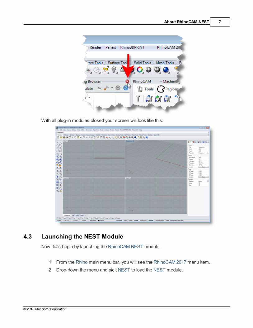
With all plug-in modules closed your screen will look like this:
4.3 Launching the NEST Module
Now, let's begin by launching the RhinoCAM-NEST module.
1. From the Rhino main menu bar, you will see the RhinoCAM 2017 menu item.
2. Drop-down the menu and pick NEST to load the NEST module.

RhinoCAM-NEST© 2017 Quick Start Guide8
© 2016 MecSoft Corporation
3. Docked on the left you will see the Nesting Browser. Notice that it is organized intotabs representing each step in the nesting process.
4. You can resize the width of the browser making sure that all of the command iconsand menus are easily accessible.

About RhinoCAM-NEST 9
© 2016 MecSoft Corporation

RhinoCAM-NEST© 2017 Quick Start Guide10
© 2016 MecSoft Corporation
Rectangular Nesting
5.1 Getting Ready
5.1.1 Load the Part File
Now, let's load the Part file containing the geometry for nesting.
1. Select File / Open from the Main Menu bar, or click the Open icon from the Standardbar.
2. From the Open dialog box, select the RectangularNestQuickStartTutorial.3dm filefrom the C:\ProgramData\MecSoft Corporation\RhinoCAM 2017 for Rhino 5.0\QuickStart\ folder. As mentioned before, it is advisable to make a copy of this part ata suitable alternative folder so that you have write privileges to modify the part.

Rectangular Nesting 11
© 2016 MecSoft Corporation
By default, the ProgramData folder is "hidden" from view. Here are thesteps to Show hidden files and folders:
1. For Windows7/8 users: Go to Control Panel > Appearance andPersonalization > Folder Options.
2. Select View tab and under advanced settings select Show Hidden files andfolders, clear the check boxes for:
Hide extensions for known file types
Hide protected operating system files (Recommended)
3. Click Apply and OK.
The part appears as shown below.

RhinoCAM-NEST© 2017 Quick Start Guide12
© 2016 MecSoft Corporation
5.1.2 Basic Steps
The following basic steps are included in the nesting process:
1. First, we load the RhinoCAM-NEST module and define the Nesting Type to beperformed.
2. Then we open the Rhino drawing where the stock material and production parts arestaged.
3. Then we select the Sheets to Nest our parts in and then select the Parts to Nest.
4. We choose our desired Nesting parameters.
5. Then we Preview the Nest making any final adjustments.
6. Finally, we Commit the Nest, creating the actual nested sheet geometry.
5.1.3 Staging your Parts
Let's take a look at what we've done in Rhino to prepare for nesting. You can refer to this asthe Staging Process. We have brought together and located on the screen, the geometry thatwe want in the nesting process.
As you can see, we have one or more shapes that represent the stock or the remnantmaterial. We also have one of more shapes that represent the production parts that we wantto nest within the stock material.
Here are two tips to consider when staging your parts.
First, when you stage your parts, stage them around the outside of thestock material, not within the stock material. The Nesting software will
Rectangular Nesting 13
© 2016 MecSoft Corporation
place the parts in the stock for you.
Secondly, do not place parts inside the cutouts of larger parts as this mayconfuse the Nesting software into thinking that it is a detail of the larger part.
Keep all of your parts separated.
5.2 Creating a Rectangular Nest
5.2.1 Choose Nesting Type
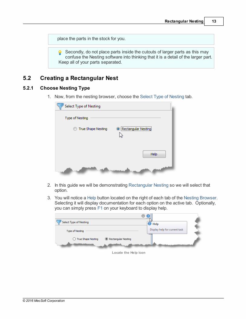
1. Now, from the nesting browser, choose the Select Type of Nesting tab.
2. In this guide we will be demonstrating Rectangular Nesting so we will select thatoption.
3. You will notice a Help button located on the right of each tab of the Nesting Browser. Selecting it will display documentation for each option on the active tab. Optionally,you can simply press F1 on your keyboard to display help.
Locate the Help icon

RhinoCAM-NEST© 2017 Quick Start Guide14
© 2016 MecSoft Corporation
Rectangular Nesting 15
© 2016 MecSoft Corporation
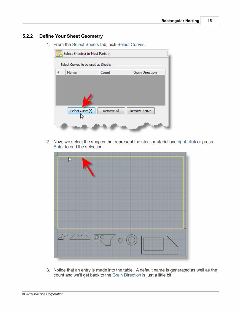
5.2.2 Define Your Sheet Geometry
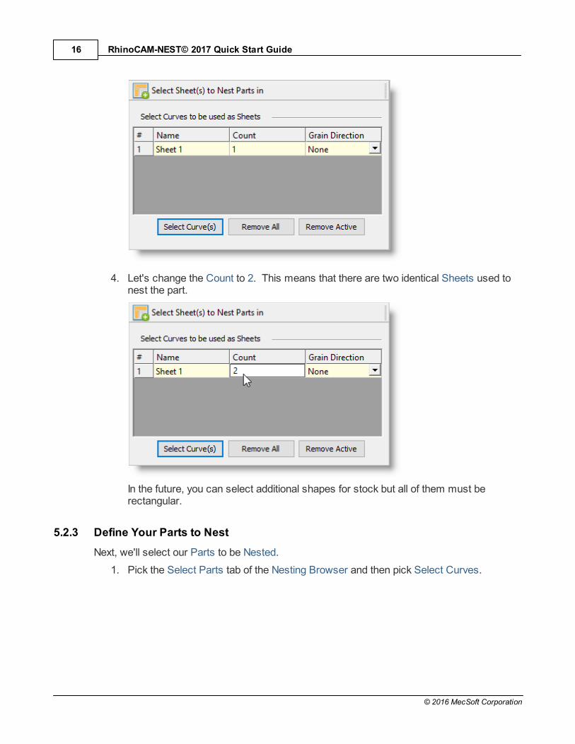
1. From the Select Sheets tab, pick Select Curves.
2. Now, we select the shapes that represent the stock material and right-click or pressEnter to end the selection.
3. Notice that an entry is made into the table. A default name is generated as well as thecount and we'll get back to the Grain Direction is just a little bit.
RhinoCAM-NEST© 2017 Quick Start Guide16
© 2016 MecSoft Corporation
4. Let's change the Count to 2. This means that there are two identical Sheets used tonest the part.
In the future, you can select additional shapes for stock but all of them must berectangular.
5.2.3 Define Your Parts to Nest
Next, we'll select our Parts to be Nested.
1. Pick the Select Parts tab of the Nesting Browser and then pick Select Curves.

Rectangular Nesting 17
© 2016 MecSoft Corporation
2. Then we will window select all of our part geometry and then right-click or press Enterto add each part to the Parts List of the Nesting Browser.

RhinoCAM-NEST© 2017 Quick Start Guide18
© 2016 MecSoft Corporation
The Nesting software determines the exterior and interior of each selected part.
As we can see in the Parts List, each exterior closed curve is defined as one Part. Any interior closed curves are defined as Holes within each Part.
3. If we select a part from the parts list we see that it is highlighted in the graphicswindow.
4. If a part has multiple interior cutouts, each is listed in the Parts List, under itsassociated part.
Rectangular Nesting 19
© 2016 MecSoft Corporation
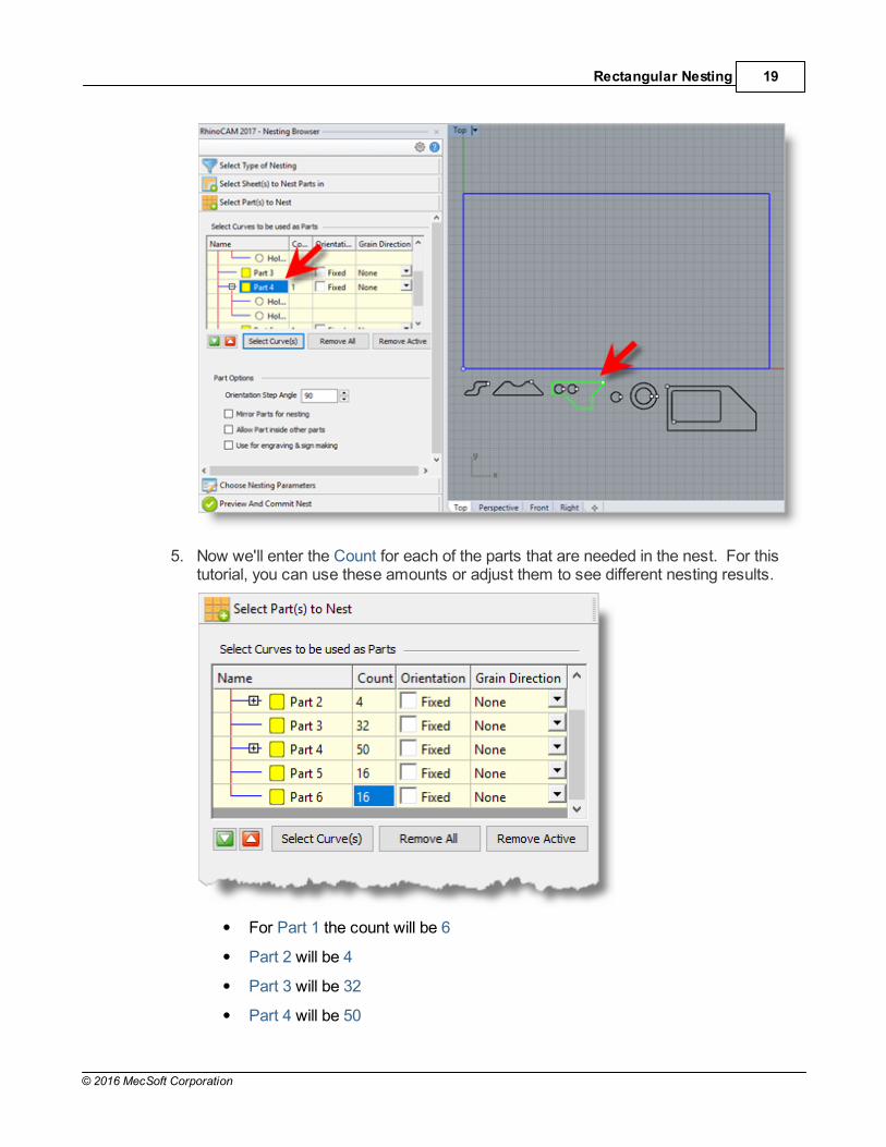
5. Now we'll enter the Count for each of the parts that are needed in the nest. For thistutorial, you can use these amounts or adjust them to see different nesting results.
For Part 1 the count will be 6
Part 2 will be 4
Part 3 will be 32
Part 4 will be 50

RhinoCAM-NEST© 2017 Quick Start Guide20
© 2016 MecSoft Corporation
Part 5 will be 16
and for Part 6 will have a count of 32
5.2.4 Choose Nesting Parameters
Now, we'll select the Choose Nesting Parameters tab of the Nesting Browser to set two finalparameters.
1. The first one sets the Distance Part to Part. We'll enter 0.15 there.
2. The second is the Distance Part to Sheet (i.e., the distance between the outer-mostparts and the outer edge of the stock material). We'll set that to 0.25.
There are also options to automatically Tag each nested part and layout options forarranging your nested sheets.
3. Now we select Execute Nest and then Preview Nest. Notice that you are moved tothe Preview and Commit Nest tab automatically and you see that 2 sheets will beused.

Rectangular Nesting 21
© 2016 MecSoft Corporation
RhinoCAM-NEST© 2017 Quick Start Guide22
© 2016 MecSoft Corporation
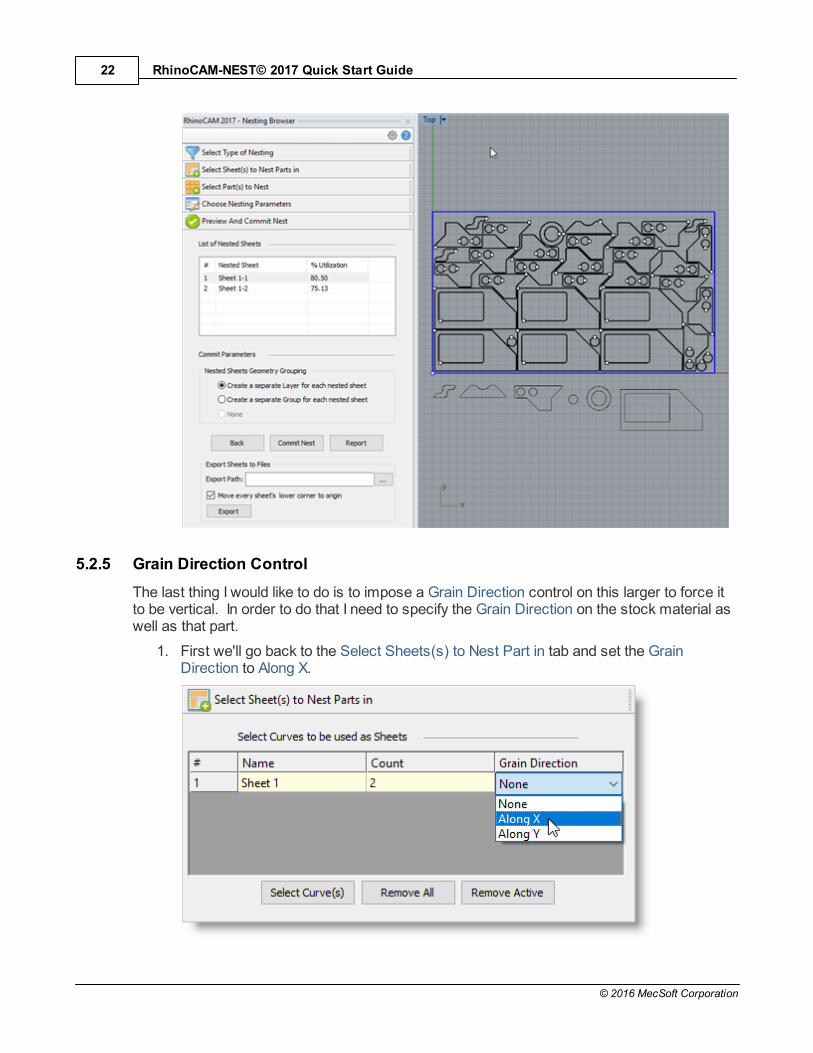
5.2.5 Grain Direction Control
The last thing I would like to do is to impose a Grain Direction control on this larger to force itto be vertical. In order to do that I need to specify the Grain Direction on the stock material aswell as that part.
1. First we'll go back to the Select Sheets(s) to Nest Part in tab and set the GrainDirection to Along X.

Rectangular Nesting 23
© 2016 MecSoft Corporation
2. Then on the Select Parts tab I will set the Grain Direction on this larger part to beAlong Y.
5.2.6 Execute, Preview, Commit the Nest
Now we'll select the Choose Nesting Parameters tab, we'll Execute and Preview the nestagain and we see that the part is now aligned vertically.

RhinoCAM-NEST© 2017 Quick Start Guide24
© 2016 MecSoft Corporation
Each time the nest is generated, the system will calculate an Efficiency Factor referred to as% Utilization of the stock material.
For Nested Sheet Geometry Grouping we'll select the Separate Layer option.
Rectangular Nesting 25
© 2016 MecSoft Corporation
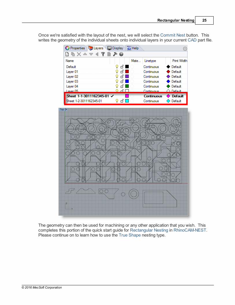
Once we're satisfied with the layout of the nest, we will select the Commit Nest button. Thiswrites the geometry of the individual sheets onto individual layers in your current CAD part file.
The geometry can then be used for machining or any other application that you wish. Thiscompletes this portion of the quick start guide for Rectangular Nesting in RhinoCAM-NEST. Please continue on to learn how to use the True Shape nesting type.
RhinoCAM-NEST© 2017 Quick Start Guide26
© 2016 MecSoft Corporation
True Shape Nesting
6.1 Getting Ready
6.1.1 Load the Part File
Now, let's load the Part file containing the geometry for nesting.
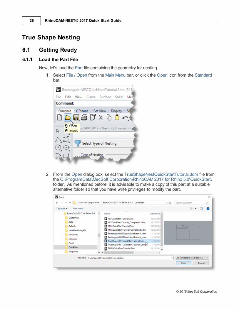
1. Select File / Open from the Main Menu bar, or click the Open icon from the Standardbar.
2. From the Open dialog box, select the TrueShapeNestQuickStartTutorial.3dm file fromthe C:\ProgramData\MecSoft Corporation\RhinoCAM 2017 for Rhino 5.0\QuickStart\folder. As mentioned before, it is advisable to make a copy of this part at a suitablealternative folder so that you have write privileges to modify the part.

True Shape Nesting 27
© 2016 MecSoft Corporation
By default, the ProgramData folder is "hidden" from view. Here are thesteps to Show hidden files and folders:
1. For Windows7/8 users: Go to Control Panel > Appearance andPersonalization > Folder Options (Windows XP users can locate folderoptions under Control Panel).
2. Select View tab and under advanced settings select Show Hidden files andfolders, clear the check boxes for:
Hide extensions for known file types
Hide protected operating system files (Recommended)
3. Click Apply and OK.
The part appears as shown below.

RhinoCAM-NEST© 2017 Quick Start Guide28
© 2016 MecSoft Corporation
6.1.2 Basic Steps
The following basic steps are included in the nesting process:
1. First, we load the RhinoCAM-NEST module and define the Nesting Type to beperformed.
2. Then we open the Rhino drawing where the stock material and production parts arestaged.
3. Then we select the Sheets to Nest our parts in and then select the Parts to Nest.
4. We choose our desired Nesting Parameters.
5. Then we Preview the Nest making any final adjustments.
6. Finally, we Commit the Nest, creating the actual nested sheet geometry.
6.1.3 Staging your Parts
Let's take a look at what we've done in Rhino to prepare for nesting. You can refer to this asthe Staging Process. We have brought together and located on the screen, the geometry thatwe want in the nesting process.
As you can see, we have one or more shapes that represent the stock or the remnantmaterial. We also have one of more shapes that represent the production parts that we wantto nest within the stock material.
Here are two tips to consider when staging your parts.
First, when you stage your parts, stage them around the outside of thestock material, not within the stock material. The Nesting software will
place the parts in the stock for you.
Secondly, do not place parts inside the cutouts of larger parts as this mayconfuse the Nesting software into thinking that it is a detail of the larger part.
True Shape Nesting 29
© 2016 MecSoft Corporation
Keep all of your parts separated.
6.2 Creating a True Shape Nest
6.2.1 Choose Nesting Type
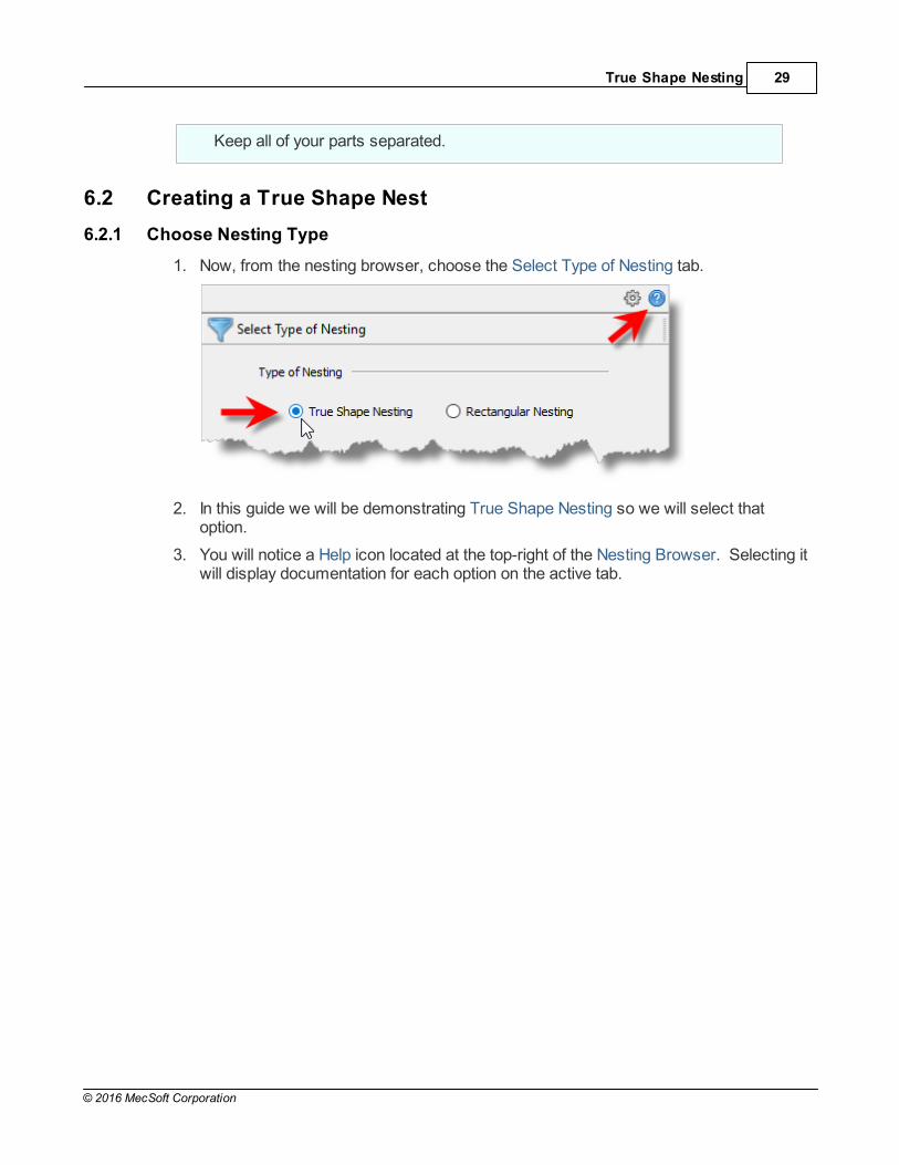
1. Now, from the nesting browser, choose the Select Type of Nesting tab.
2. In this guide we will be demonstrating True Shape Nesting so we will select thatoption.
3. You will notice a Help icon located at the top-right of the Nesting Browser. Selecting itwill display documentation for each option on the active tab.
RhinoCAM-NEST© 2017 Quick Start Guide30
© 2016 MecSoft Corporation
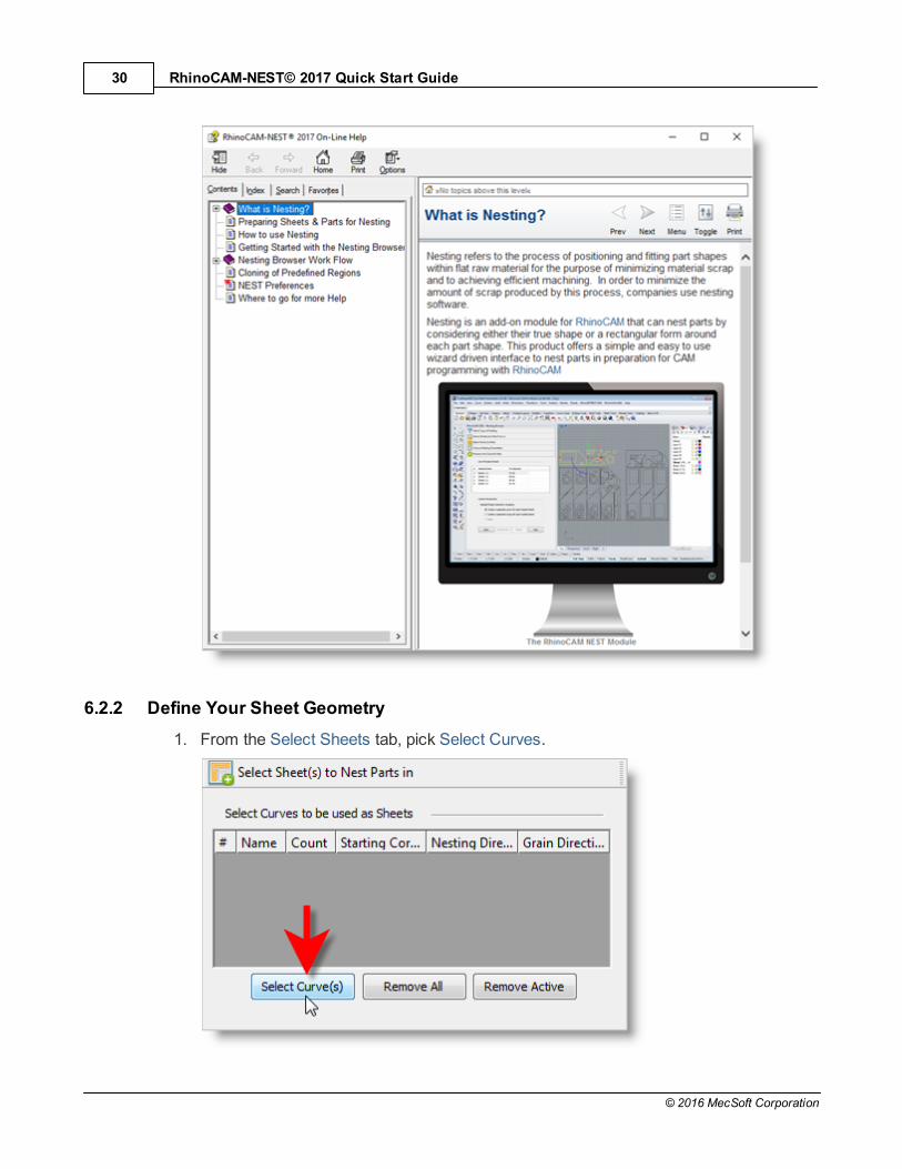
6.2.2 Define Your Sheet Geometry
1. From the Select Sheets tab, pick Select Curves.

True Shape Nesting 31
© 2016 MecSoft Corporation
2. Now, we select the shapes that represent the stock material and right-click or pressEnter to end the selection.
3. Notice that entries are made into the table for Sheet 1 and Sheet 2.
4. For the Count column, let's enter 2 sheets of each of these for the sake of nesting..

RhinoCAM-NEST© 2017 Quick Start Guide32
© 2016 MecSoft Corporation
The Starting Corner and Nesting Direction columns allow you to control where thenesting should begin and in what direction it should proceed. This is good for remnantcontrol.
We'll come back to the Grain Direction column is little bit later.
6.2.3 Define Your Parts to Nest
Next, we'll select our Parts to be Nested.
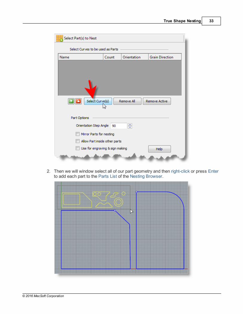
1. Pick the Select Parts tab of the Nesting Browser and then pick Select Curves.
True Shape Nesting 33
© 2016 MecSoft Corporation
2. Then we will window select all of our part geometry and then right-click or press Enterto add each part to the Parts List of the Nesting Browser.

RhinoCAM-NEST© 2017 Quick Start Guide34
© 2016 MecSoft Corporation
The Nesting software determines the exterior and interior of each selected part.
As we can see in the Parts List, each exterior closed curve is defined as one Part. Any interior closed curves are defined as Holes within each Part.
3. If we select a Part from the Parts List we see that the Part is highlighted in thegraphics window. Note: Due to algorithmic nature of the Nesting software, your partsmight be assigned different numbers as we see here in the tutorial.
4. Selecting a Hole under a part in he Parts List highlights the associated interior curve ofthat part in the graphics window. As you can see, when a part has multiple interiorcutouts, each is listed in the Parts List as Hole 1, Hole 2, etc., under its associatedPart.
5. Now we'll enter the Count for each of the parts that are needed in the nest.

True Shape Nesting 35
© 2016 MecSoft Corporation
For Part 1 the count will be 66
Part 2 will be 32
Part 3 will be 50
Part 4 will be 16
Part 5 will be 16
and for Part 6 will have a count of 4
There are Part Options below the table that will apply to all of the parts.
6. Let's change the Orientation Step Angle to 45 degrees. This means that Nestingsoftware will attempt to rotate any of the parts in 45 degree increments to achieve abetter fit.
7. Let's enable the Mirroring Parts for nesting option.
8. Also enable the Allow Part inside other parts option. This will allow smaller parts to benested within the cutouts of larger parts.
9. If you have a part that you do not want rotated or mirrored, such as the one shownbelow, you can check the box next to Fixed in the Orientation column of the Part List.
The orientation of this part will be maintained in the exact orientation that it is stagedthroughout the nesting process.

RhinoCAM-NEST© 2017 Quick Start Guide36
© 2016 MecSoft Corporation
Your dialog should now look like this:
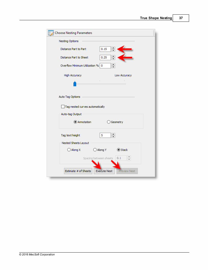
6.2.4 Choose Nesting Parameters
Now, we'll select the Choose Nesting Parameters tab of the Nesting Browser to set two finalparameters.
1. The first one sets the Distance Part to Part. We'll enter 0.15 there.
2. The second is the Distance Part to Sheet (i.e., the distance between the outer-mostparts and the outer edge of the stock material). We'll set that to 0.25.
There are also options to automatically Tag each nested part and layout options forarranging your nested sheets.
3. Now we select Execute Nest and then Preview Nest. Notice that you are moved tothe Preview and Commit Nest tab automatically and you see that 4 sheets will beused.
True Shape Nesting 37
© 2016 MecSoft Corporation

RhinoCAM-NEST© 2017 Quick Start Guide38
© 2016 MecSoft Corporation
Also notice that Part 4 (pointed to in the image below) was the one we Fixed in itsorientation, exactly as it was when it was staged.
6.2.5 Grain Direction Control
The last thing I would like to do is to impose a Grain Direction control on this larger to force itto be vertical. In order to do that I need to specify the Grain Direction on the stock material aswell as that part.
1. First we'll go back to the Select Sheets(s) to Nest Part in tab and set the GrainDirection to Along X.

True Shape Nesting 39
© 2016 MecSoft Corporation
2. When the message displays warning you that all sheets must have the same GrainDirection, pick OK and the Grain Direction for both sheets will be changed. This iswhat we want.
3. Now, on the Select Parts to Nest tab I will set the Grain Direction on Part 1 to be AlongY.

RhinoCAM-NEST© 2017 Quick Start Guide40
© 2016 MecSoft Corporation
6.2.6 Execute, Preview, Commit the Nest
Now we'll Execute and Preview the Nest once again:
1. Select the Choose Nesting Parameters tab
2. Select Execute Nest and then select Preview Nest and we see that Part 6 is nowaligned vertically.

True Shape Nesting 41
© 2016 MecSoft Corporation
3. Each time the Nest is generated, the system will calculate an Efficiency Factorreferred to as % Utilization of the stock material for each Sheet, shown below.
4. Once we're satisfied with the layout of the nest, we will select the Commit Nest button. This writes the geometry of the individual sheets onto individual layers in your current CAD part file.

RhinoCAM-NEST© 2017 Quick Start Guide42
© 2016 MecSoft Corporation
The geometry can then be used for machining or any other application that you wish.

Where to go for more help 43
© 2016 MecSoft Corporation
Where to go for more help
We have come to the end of the Quick Start Guide for RhinoCAM-NEST. This tutorial is justsample of the many functions and controls available in the NEST module. Please explore theproduct in more depth to get a feel for how these functions and controls operate.
If you need additional help please use the following resources:
The on-line help distributed with the product is a great resource to find referenceinformation on the various functions available.
Apart from the on-line help system you can download other tutorials and projects from MecSoft Corporation's web site at www.mecsoft.com.
If you need additional help, or if you have any questions regarding RhinoCAM-NEST,you may contact us via e-mail at [email protected]
MecSoft offers Online training as well as personalized full day training sessions.Please look up our website or email us at [email protected] for further details
Please do continue to visit our home page to learn about the latest updates to RhinoCAM-NEST and any other help material.

RhinoCAM-NEST© 2017 Quick Start Guide44
© 2016 MecSoft Corporation
Index- A -About the NEST Module 3
- B -Basic Steps
Load the Part File 10
Rectangular Nesting 12
True Shape Nesting 28
- C -Choose Nesting Parameters
Rectangular Nesting 20
True Shape Nesting 36
Choose Nesting Type
Rectangular Nesting 13
True Shape Nesting 29
Commit the Nest
Rectangular Nesting 23
True Shape Nesting 40
- D -Define Your Parts to Nest
Rectangular Nesting 16
True Shape Nesting 32
Define Your Sheet Geometry
Rectangular Nesting 15
True Shape Nesting 30
- E -Execute the Nest
Rectangular Nesting 23
True Shape Nesting 40
- G -Grain Direction Control
Rectangular Nesting 22
True Shape Nesting 38
- L -Launching the NEST Module 7
Load the Part File
True Shape Nesting 26
- N -NEST Module
Launching 7
- P -Preview the Nest
Rectangular Nesting 23
True Shape Nesting 40
- R -Rectangular Nesting
Basic Steps 12
Choose Nesting Parameters 20
Choose Nesting Type 13
Commit the Nest 23
Define Your Parts to Nest 16
Define Your Sheet Geometry 15
Execute the Nest 23
Grain Direction Control 22
Load the Part File 10
Preview the Nest 23
Staging your Parts 12
- S -Staging your Parts
Rectangular Nesting 12
True Shape Nesting 28
- T -True Shape Nesting
Basic Steps 28
Choose Nesting Parameters 36
Choose Nesting Type 29

Index 45
© 2016 MecSoft Corporation
True Shape Nesting
Commit the Nest 40
Define Your Parts to Nest 32
Define Your Sheet Geometry 30
Execute the Nest 40
Grain Direction Control 38
Load the Part File 26
Preview the Nest 40
Staging your Parts 28
Where to go for more help 43
- U -Useful Tips 5
Using this Guide 4
- W -Where to go for more help
True Shape Nesting 43


