RIA Failure of High Burn-up Fuel Rod Irradiated in KKL: Out-of-Pile Mechanical Simulation and Comparison with Pulse Reactor Tests V. Grigoriev 1) , R. Jakobsson 1) , D. Schrire 2) , G. Ledergerber 3) , T. Sugiyama 4) , F. Nagase 4) , T. Fuketa 4) , L. Hallstadius 5) , S. Valizadeh 5) Studsvik Nuclear AB 1) , Vattenfall Fuel AB 2) , Kernkraftwerk Leibstadt AG 3) , Japan Atomic Energy Agency 4) , Westinghouse Electric Sweden AB 5) , 16th ASTM International Symposium Zirconium in the Nuclear Industry 09-13 May, 2010, Chengdu, China
Transcript
RIA Failure of High Burn-up Fuel RodIrradiated in KKL:Out-of-Pile Mechanical Simulationand Comparison withPulse Reactor Tests
V. Grigoriev 1), R. Jakobsson 1), D. Schrire 2), G. Ledergerber 3),T. Sugiyama 4), F. Nagase 4), T. Fuketa 4),
L. Hallstadius 5), S. Valizadeh 5)
Studsvik Nuclear AB 1), Vattenfall Fuel AB 2),Kernkraftwerk Leibstadt AG 3), Japan Atomic Energy Agency 4),Westinghouse Electric Sweden AB 5),
16th ASTM International Symposium Zirconium in the Nuclear Industry09-13 May, 2010, Chengdu, China
2RIA – EDC – NSRR
16th ASTM International Symposium Zirconium in the Nuclear Industry, 09-13 May, 2010, Chengdu, China
Outline
• Background• Characteristics of the rod AEB072-E4• Main results from the NSRR tests LS-1 and LS-2• Main results from the EDC tests:
- effect of test temperature- effect of hydrogen concentration- effect of rapid heating
• Comparison between the NSRR and EDC test results• Summary
3RIA – EDC – NSRR
16th ASTM International Symposium Zirconium in the Nuclear Industry, 09-13 May, 2010, Chengdu, China
Background (1)
• Main specific of an RIA:- rapid heating of fuel resulting in rapid expansion of fuel pellet
• Two factors determine the risk for cladding failure due to PCMI:- reduced ductility of cladding- excess of fuel enthalpy during an RIA
• Pulse irradiation RIA tests provide the basis for establishing of fuelenthalpy limits
• High strain rate mechanical tests on cladding are needed for betterunderstanding of the results obtained in research pulse reactor RIAtests
4RIA – EDC – NSRR
16th ASTM International Symposium Zirconium in the Nuclear Industry, 09-13 May, 2010, Chengdu, China
Background (2)In the present work:
• High burn-up fuel rod AEB072-E4 (63 GWd/t) has been irradiated inthe Leibstadt BWR NPP in Switzerland (KKL)
• Two samples (LS-1 and LS-2) prepared from fuel rod AEB072-E4have been tested in the Japanese Nuclear Safety Research Reactor(NSSR) for the simulated reactivity initiated accident (RIA) within theframework of the Advanced LWR Fuel Performance and SafetyResearch Program (ALPS).
• Samples from the sister segment of the same fuel rod AEB072-E4have been subjected at Studsvik to the high strain rate mechanicaltesting by means of the Expansion-Due-to-Compression (EDC) testtechnique.
• To evaluate an effect of burnup and, consequently, an effect ofhydrogen content additional EDC tests have been performed onlower burnup fuel rods (AEB068-E4, AEB069-E4 and 20461-J2) withthe same type of cladding material.
5RIA – EDC – NSRR
16th ASTM International Symposium Zirconium in the Nuclear Industry, 09-13 May, 2010, Chengdu, China
Original fuel rod AEB072-E4
Power history for segments J and Hforeseen for RIA (NSRR) and
mechanical (EDC) testing, respectively
Fuel rod AEB072-E4Irradiation (cycles)Pellet enrichment (%)Rod average burnup (MWd/kg)Rod growth, pool / hot cell (%)Fission Gas Release (%)Cladding materialRod average total hydrogen (ppm)Standard deviationRadial hydride fraction (%)
74.4662.9
0.42 / 0.401.1
Zircaloy-2 (LK3 with liner)305
< 10%7
6RIA – EDC – NSRR
16th ASTM International Symposium Zirconium in the Nuclear Industry, 09-13 May, 2010, Chengdu, China
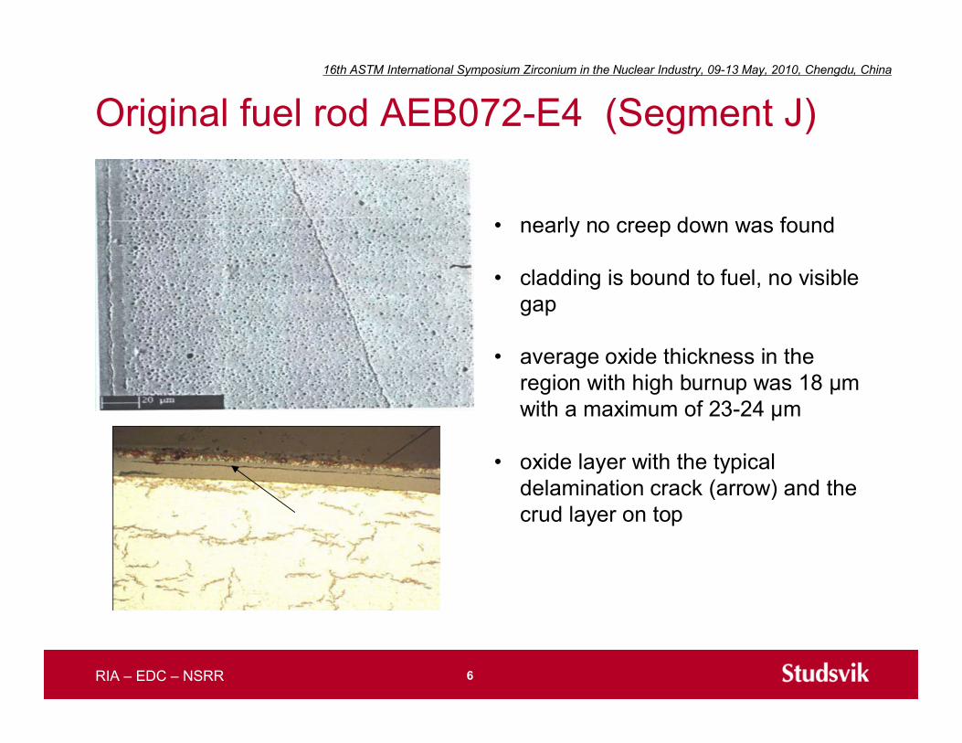
Original fuel rod AEB072-E4 (Segment J)
• nearly no creep down was found
• cladding is bound to fuel, no visiblegap
• average oxide thickness in theregion with high burnup was 18 µmwith a maximum of 23-24 µm
• oxide layer with the typicaldelamination crack (arrow) and thecrud layer on top
7RIA – EDC – NSRR
16th ASTM International Symposium Zirconium in the Nuclear Industry, 09-13 May, 2010, Chengdu, China
Original fuel rod AEB072-E4 (Segment J)
• fractionated determination ofhydrogen in fuel claddingresulted in a value of 90% ofhydrogen in the metal and 10%of hydrogen being released atlower temperature presumablyfrom oxide
• calculated average value of totalhydrogen for segment J (RIA-NSRR) is 305 ppm
8RIA – EDC – NSRR
16th ASTM International Symposium Zirconium in the Nuclear Industry, 09-13 May, 2010, Chengdu, China
• Two pulse irradiation tests have been performed under almostidentical irradiation conditions (pulse width ~ 4 ms)
• RT test (LS-1): sample length 150 mm
• HTHP test (LS-2): sample length 90 mm
RIA NSRR tests on AEB072-E4 (J)
Pulse irradiation NSRR tests LS-1 LS-24.4 Power pulse width, ms
16th ASTM International Symposium Zirconium in the Nuclear Industry, 09-13 May, 2010, Chengdu, China
EDC tests on AEB072-E4 (H)
• “Expansion-Due-to-Compression” (EDC)test using a soft mandrel (polymer pellet)
• Simulation of PCMI experienced by thecladding during RIA
• Plunger displacement: 2,9 mm
• Time for displacement: ~80 ms
• Laser monitoring of specimen diameter
• Test temperatures for AEB072-E4specimens: 60 – 260°C
Specimen
PolymerPellet
Plunger
Plunger
Diameter
Load / Displacement
2.9mm / 80ms
10RIA – EDC – NSRR
16th ASTM International Symposium Zirconium in the Nuclear Industry, 09-13 May, 2010, Chengdu, China
EDC test data on AEB072-E4 (H)
0
5
10
15
20
25
30
0 50 100 150 200 250 300
Test Temperature (°C)
Max
imum
Hoo
p St
rain
(%)
non-failed
failed
250 - 350 ppm H
• An abrupt increase of the specimen hoop strain at failure appears tooccur at temperatures of about 150-180°C
-0,2
0,2
0,6
1
1,4
1,8
2,2
-12 -8 -4 0 4 8 12Axial position (mm)
Dia
met
er in
crea
se (m
m)
160°C / Failed
180°C / Not failed
180°C
160°C
7 cycles
11RIA – EDC – NSRR
16th ASTM International Symposium Zirconium in the Nuclear Industry, 09-13 May, 2010, Chengdu, China
Effect of burn-up on the EDC test data
• Peak strain to failure shows a sharp transition from a “lower” to an “upper”shelf of ductility
• Higher burn-up (?) / hydrogen concentrations (?) result in the higher transitiontemperature and in lower hoop strain at failure for ambient temperatures
0
5
10
15
20
25
30
0 50 100 150 200 250 300 350Test Temperature (°C)
Stra
in a
t Fai
lure
or M
axim
um H
oop
Stra
in(%
)60 - 130 ppm H
non-failedfailed
non-failedfailed
250 - 350 ppm H
AEB 072-E4 (63 MWd/kgU)
20461-J2 (40 MWd/kgU)
0
5
10
15
20
25
30
0 50 100 150 200 250 300 350Test Temperature (°C)
Stra
in a
t Fai
lure
or M
axim
um H
oop
Stra
in(%
)60 - 130 ppm H
non-failedfailed
non-failedfailed
250 - 350 ppm H
AEB 072-E4 (63 MWd/kgU)
20461-J2 (40 MWd/kgU)
12RIA – EDC – NSRR
16th ASTM International Symposium Zirconium in the Nuclear Industry, 09-13 May, 2010, Chengdu, China
Hydrogen in EDC samples AEB072-E4
• Numbers in the graph represents hydrogen concentration obtained by HVE from theEDC samples after testing
• Both temperature and hydrogen concentration appear to affect hoop strain at failure• In general, higher hydrogen concentration results in lower hoop strain at failure• Total hoop strain at failure at lower shelf is 0.7-1.2 %
0
5
10
15
20
25
30
0 50 100 150 200 250 300 350Test Temperature (°C)
Max
imum
Hoo
p St
rain
(%)
371
298
349
253
13RIA – EDC – NSRR
16th ASTM International Symposium Zirconium in the Nuclear Industry, 09-13 May, 2010, Chengdu, China
Hydrogen and Temperature Effect onEDC Specimen Failure (irradiated)
• All available EDC data are plotted in the diagram• Hydrogen appears to define the transition temperature: TBDT(°C)=0,7*H(ppm)
0
100
200
300
400
500
0 200 400 600 800 1000 1200Hydrogen in EDC Specimen (ppm)
EDC
Tes
t Tem
pera
ture
(°C
)
No FailureFailureSeries3AEB 072-E4Series5Series6Linear (Series3)
Failure
No Failure
Zr-2 / Zr-4 / ZIRLO( 40 ÷ 70 MWd/kgU )
AEB 068-E4AEB 069-E420461-J2
TBDT (°C) = 0.7 H (ppm)
Zr-4
0
100
200
300
400
500
0 200 400 600 800 1000 1200Hydrogen in EDC Specimen (ppm)
EDC
Tes
t Tem
pera
ture
(°C
)
No FailureFailureSeries3AEB 072-E4Series5Series6Linear (Series3)
Failure
No Failure
Zr-2 / Zr-4 / ZIRLO( 40 ÷ 70 MWd/kgU )
AEB 068-E4AEB 069-E420461-J2
TBDT (°C) = 0.7 H (ppm)
Zr-4
14RIA – EDC – NSRR
16th ASTM International Symposium Zirconium in the Nuclear Industry, 09-13 May, 2010, Chengdu, China
NSRR and EDC test conditions:Similarity and Differences
• EDC is reproducing in-reactor loading rates under statictemperature conditions
• EDC specimen is pressurized from inner side similar toin-reactor conditions. As a difference, an additional axialbending component of loading due to specimenballooning is present in the EDC test. The bending ismore pronounced in ductile specimens.
• Beside the presence of neutrons the main differencebetween the NSRR and the EDC test conditions is theheating, which is static in the EDC and dynamic in theNSRR
15RIA – EDC – NSRR
16th ASTM International Symposium Zirconium in the Nuclear Industry, 09-13 May, 2010, Chengdu, China
Rapid Heating/Loading (RHL) test
• Direct current heating
• Infra-red sensor for temperaturemeasurements
• Clip-gauge for elongation measurements
• Data record frequency 1 kHz
• Heating/Loading within 30-80 ms
• Material for testing (unirradiated):hydrided Zircaloy fuel channel plate(~500 ppm)
IR temperaturesensor
Thermocouplefor calibrationmeasurements
Development of the RHL test and testing of unirradiated hydrided Zircaloyplate material have been initiated and sponsored by EPRI
To verify an effect of rapid heating a new test procedure has been recentlydeveloped
16RIA – EDC – NSRR
16th ASTM International Symposium Zirconium in the Nuclear Industry, 09-13 May, 2010, Chengdu, China
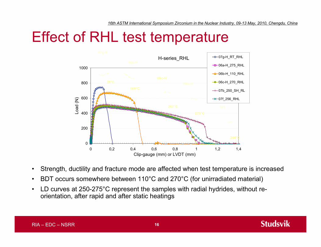
Effect of RHL test temperature
• Strength, ductility and fracture mode are affected when test temperature is increased• BDT occurs somewhere between 110°C and 270°C (for unirradiated material)• LD curves at 250-275°C represent the samples with radial hydrides, without re-
orientation, after rapid and after static heatings
16th ASTM International Symposium Zirconium in the Nuclear Industry, 09-13 May, 2010, Chengdu, China
Strength and ductility in the RHL tests
• Strength and ductility of hydrided material depend on instantaneoustemperature or are very fast adapted to the actual temperature and arenot affected by the applied heating time (rate of heating)
18RIA – EDC – NSRR
16th ASTM International Symposium Zirconium in the Nuclear Industry, 09-13 May, 2010, Chengdu, China
NSRR test results LS-1 and LS-2 in theco-ordinates of EDC test data
16th ASTM International Symposium Zirconium in the Nuclear Industry, 09-13 May, 2010, Chengdu, China
NSRR test LS-1
10 μm
… a lot of small dimples inin the inner part of cladding
20RIA – EDC – NSRR
16th ASTM International Symposium Zirconium in the Nuclear Industry, 09-13 May, 2010, Chengdu, China
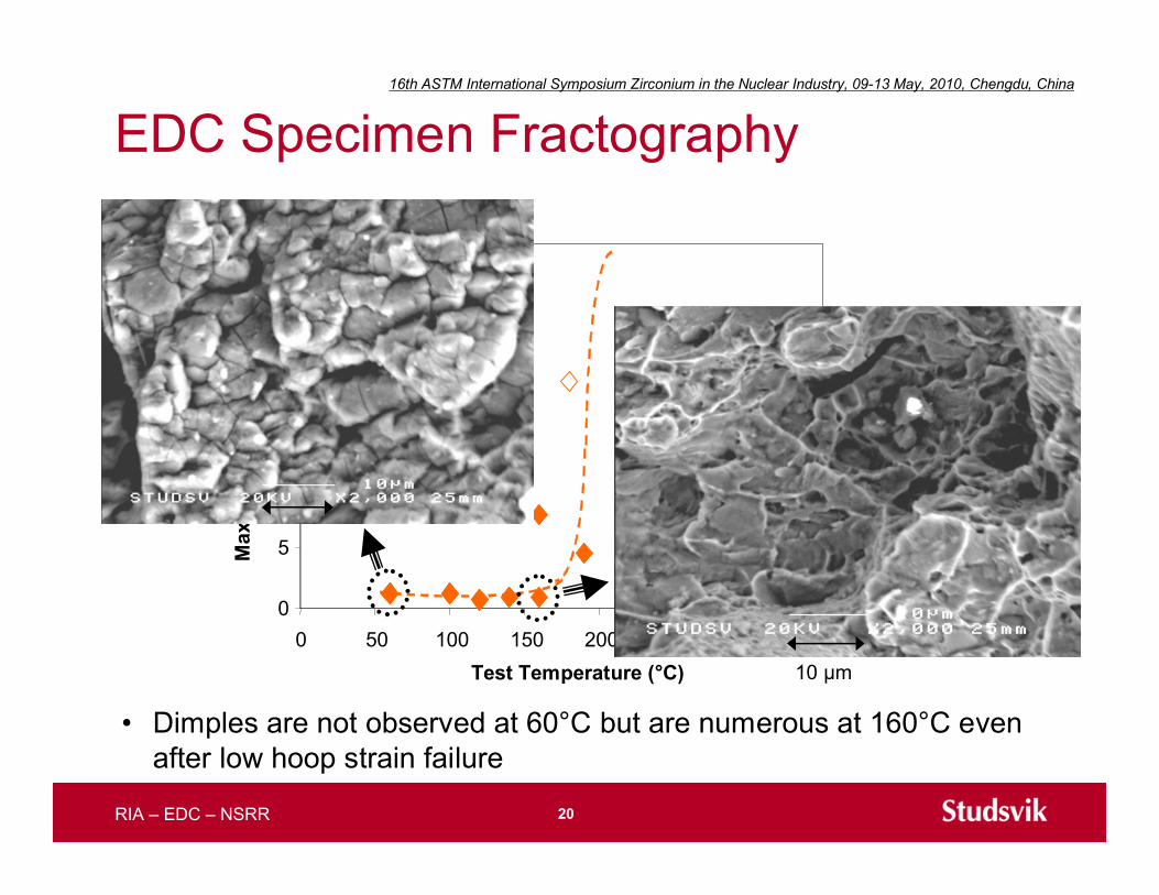
EDC Specimen Fractography
• Dimples are not observed at 60°C but are numerous at 160°C evenafter low hoop strain failure
0
5
10
15
20
25
30
0 50 100 150 200 250 300 350Test Temperature (°C)
Max
imum
Hoo
p St
rain
(%)
10 μm
21RIA – EDC – NSRR
16th ASTM International Symposium Zirconium in the Nuclear Industry, 09-13 May, 2010, Chengdu, China
Summary
• A segment of a high burn-up BWR fuel rod has been subjected to in-reactorsimulated RIA tests at ambient (test LS-1) and operating temperatures (testLS-2). Two ramp tests carried out under almost identical irradiationconditions resulted in specimen failure in the LS-1 test while no failure wasobserved in the LS-2 test.
• High strain rate mechanical EDC tests performed on fuel cladding of thesame rod clearly indicate separate “failure” and “non-failure” regions in thefailure map based on the EDC test data. A simple relationship defining thetransition temperature versus hydrogen concentration in the cladding hasbeen obtained.
• Heating rate does not appear to affect the cladding strength and ductilityand, thus, one can compare the effect of temperature on cladding fracture inthe EDC tests and in the pulse irradiation tests. The in-reactor LS-1 and LS-2test results show good consistency with the failure map based on the EDCtest data. It is concluded that the failure of high burnup fuel under RIAconditions is mainly controlled by temperature and hydrogen concentration,and that the EDC test can provide valuable information to predict fuel failure.
22RIA – EDC – NSRR
16th ASTM International Symposium Zirconium in the Nuclear Industry, 09-13 May, 2010, Chengdu, China
Main references• Ledergerber, G., Abolhassani, S., Limbäck, M., et.al.. “Characterization of
High Burn up Fuel for safety related fuel testing”, Jour. Science andTechnology, Vol 43, No 9, pp. 1006-1014.
• Grigoriev, V., Schrire, D., Jakobsson, R., et.al. “Mechanical Testing of HighBurnup PWR Cladding to Simulate RIA,” Proceedings of Annual Meeting onNuclear Technology 2000: JAHRESTAGUNG KERTECHNIK, Bonn, 23-25May, 2000, pp. 359-362. ISSN 0720-9207.
• Tägtström, P., Limbäck, M., Dahlbäck, M., et.al., “Effects of Hydrogen Pickupand Second Phase Particle Dissolution on the In-Reactor CorrosionPerformance of BWR Claddings”, ASTM STP 1423, 2002, pp.96-118.
• Sugiyama, T., Umeda, M., Fuketa, T., et.al. “Failure of high burnup fuelsunder reactivity-initiated accident conditions,” Annals of Nuclear Energy, Vol.36, 2009, pp. 380-385.
• Yueh, K., “Rapid Heating and Loading Test”, ADAMS, ML090861034.
23RIA – EDC – NSRR
16th ASTM International Symposium Zirconium in the Nuclear Industry, 09-13 May, 2010, Chengdu, China
Acknowledgements
• Vattenfall AB, OKG Aktiebolag, Barseback Kraft AB, WestinghouseElectric Sweden AB, and Studsvik AB sponsored the development ofthe EDC test and, together with Kernkraftwerk Leibstadt AG, themechanical testing of irradiated cladding from the rod AEB072-E4.
• Electric Power Research Institute proposed and sponsored thedevelopment of the RHL test as well as the tests on unirradiatedhydrided Zircaloy plate material. Special thanks to Ken Yueh forcontinuing discussions and aid.
• The authors would like to acknowledge Sousan Abholassani, DidierGavillet and Holger Wiese (PSI) as well as Roger Lundström andSören Karlsson (Studsvik) for material characterisation.
24RIA – EDC – NSRR
16th ASTM International Symposium Zirconium in the Nuclear Industry, 09-13 May, 2010, Chengdu, China
25RIA – EDC – NSRR
16th ASTM International Symposium Zirconium in the Nuclear Industry, 09-13 May, 2010, Chengdu, China
TABLE 3— Fuel description, test conditions and main results of the NSRR RIA tests.
ID for test and test fuel rod LS-1 LS-2
Description of mother fuel rod Fuel type Clad outer/inner diameter, mm Clad material Pellet burnup, GWd/t
10x10 BWR-UO2 (Leibstadt)9.62 / 8.36
Zircaloy-2 (LK3) with Zr liner69
25300107
2529052
Description of test fuel rods Clad oxide thickness, µm Clad hydrogen content, ppm Pellet stack length, mm Rod internal gas helium of 0.1 MPa at ~20 °C
4.4Test conditions Power pulse width, ms Initial coolant conditions (stagnant water) Initial fuel enthalpy (20 °C-based), H0, J/g (cal/g) Max. increase of fuel enthalpy,
DHmax, J/g (cal/g)
17 °C0.1 MPa
-
469 (112)
283 °C6.6 MPa70 (17)
371 (89)
Main results Enthalpy increase at failure,
DHfail, J/g (cal/g) Key observations
222 (53)
- PCMI failure- all pellets fragmented- mechanical energydetected