Ribbon plastic optical fiber linked optical transmitter and receiver modules featuring a
high alignment tolerance
Hak-Soon Lee,1 Jun-Young Park,
1 Sang-Mo Cha,
1 Sang-Shin Lee,
1,*
Gyo-Sun Hwang,2 and Yung-Sung Son
2
1Department of Electronic Engineering, Kwangwoon University 447-1 Wolgye-Dong, Nowon-Gu, Seoul 139-701, South Korea
2Unive Inc.,48389 Fremont Boulevard, Suite 106, Fremont, California 94538, USA *[email protected]
Abstract: Ribbon plastic optical fiber (POF) linked four-channel optical transmitter (Tx) and receiver (Rx) modules have been proposed and realized featuring an excellent alignment tolerance. The two modules share a common configuration involving an optical sub-assembly (OSA) with vertical cavity surface emitting lasers (VCSELs)/photodetectors (PDs), and their driver ICs, which are integrated onto a single printed circuit board (PCB) substrate. The OSA includes an alignment structure, a beam router and a fiber guide, which were produced by using plastic injection molding. We have accomplished a fully passive alignment between the VCSELs/PDs and the ribbon POF by taking advantage of the alignment structure that serves as a reference during the alignment of the constituent parts of the OSA. The electrical link, which largely determines the operation speed, has been remarkably shortened, due to a direct wire-bonding between the VCSELs/PDs and the driver circuits. The light sources and the detectors can be individually positioned, thereby overcoming the pitch limitations of the ribbon POF, which is made up of perfluorinated graded-index (GI) POF with a 62.5 μm core diameter. The overall alignment tolerance was first assessed by observing the optical coupling efficiency in terms of VCSEL/PD misalignment. The horizontal and vertical 3-dB alignment tolerances were about 20 μm and 150 μm for the Tx and 50 μm and over 200 μm for the Rx, respectively. The VCSEL-to-POF coupling loss for the Tx and the POF-to-PD loss for the Rx were 3.25 dB and 1.35 dB at a wavelength of 850 nm, respectively. Subsequently, a high-speed signal at 3.2 Gb/s was satisfactorily delivered via the Tx and Rx modules over a
temperature range of 30 to 70°C with no significant errors; the channel
crosstalk was below 30 dB. Finally, the performance of the prepared modules was verified by transmitting a 1080p HDMI video supplied by a Bluelay player to an LCD TV.
1. D. A. B. Miller, and H. M. Ozaktas, “Limit to the bit-rate capacity of electrical interconnects from the aspect ratio of system architecture,” J. Parallel Distrib. Comput. 41(1), 42–52 (1997).
2. D. A. B. Miller, “Physical reasons for optical interconnection,” Int. J. Optoelectron. 11, 155–168 (1997). 3. S. C. Liu, R. R. Liu, W. P. Chen, C. Z. Wu, and J. S. Pan, “Optical sub-assembly solution for single fiber optical
HDMI connector,” Proc. SPIE 7229, 722906, 722906-10 (2009). 4. J. Y. Park, H. S. Lee, S. S. Lee, and Y. S. Son, “Passively aligned transmit optical sub-assembly module based on
a WDM incorporating VCSELs,” IEEE Photon. Technol. Lett. 22(24), 1790–1792 (2010).
#138960 - $15.00 USD Received 10 Dec 2010; revised 10 Feb 2011; accepted 14 Feb 2011; published 18 Feb 2011(C) 2011 OSA 28 February 2011 / Vol. 19, No. 5/ OPTICS EXPRESS 4301
5. J. Zhang, P. V. Ramana, J. Chandrappan, C. W. Tan, Y. Y. Chai, Y. M. Khoo, W. L. Teo, J. L. H. Shing, P. O. Gomex, T. Wang, and V. M. Ramkumar, “Development of optical subassembly for plastic optical fiber transceiver in high-speed applications,” IEEE Trans. Adv. Packag. 33(2), 428–432 (2010).
6. M. S. Cohen, G. W. Johnson, J. M. Trewhella, D. L. Lacey, M. M. Oprysko, D. L. Karst, S. M. DeFoster, W. K. Hogan, M. D. Peterson, and J. A. Weirick, “Low-cost fabrication of optical subassemblies,” IEEE Trans. Compon., Packag., Manuf. Technol., Part B 20(3), 256–263 (1997).
7. E. Palen, “Low cost optical interconnects,” Proc. SPIE 6478, 647804, 647804-5 (2007). 8. A. Suzuki, Y. Wakazono, T. Ishikawa, Y. Hashimoto, H. Masuda, S. Suzuki, M. Tamura, T. Suzuki, K. Kikuchi,
H. Nakagawa, M. Aoyagi, and T. Mikawa, “Low-cost optical subassembly using VCSEL pre-self-aligned with optical fiber for optical interconnect applications,” J. Lightwave Technol. 27(20), 4516–4523 (2009).
9. S. H. Hwang, S. H. Lee, and H. H. Park, “Optical subassembly with 57°-angled fiber array and silicon optical bench for VCSEL array and parallel optical transmitter module,” Proc. SPIE 6352, 63520W (2006).
10. S. H. Hwang, J. W. Lim, and B. S. Rho, “Simple and high-accuracy integration for parallel optical subassembly with 120-Gbits/s data transmission,” Opt. Eng. 49(9), 095401 (2010).
11. G. Sialm, D. Lenz, D. Erni, G.-L. Bona, C. Kromer, M. X. Jungo, T. Morf, F. Ellinger, and H. Jackel, “Comparison of simulation and measurement of dynamic fiber-coupling effects for high-speed multimode VCSELs,” J. Lightwave Technol. 23(7), 2318–2330 (2005).
12. T. Ouchi, A. Imada, T. Sato, and H. Sakata, “Direct coupling of VCSELs to plastic optical fibers using guide holes patterned in a thick photoresist,” IEEE Photon. Technol. Lett. 14(3), 263–265 (2002).
13. J. Vinogradov, O. Ziemann, H. Poisel, E. Hartl, S. Junger, B. Offenbeck, N. Weber, B. Weickert, and H. Bauernschmitt, “HDTV data transmission over POF ribbon cables,” in Proc. POF 2007, Torino, Italy (2007), pp. 103–106.
14. Perfluorinated graded-index ribbon POF is available from Chromis Fiberoptics Co., USA. 15. G. Giaretta, W. White, M. Wegmuller, and T. Onishi, “High-speed (11 Gbit/s) data transmission using
perfluorinated graded-index polymer optical fibers for short interconnects,” IEEE Photon. Technol. Lett. 12(3), 347–349 (2000).
1. Introduction
In response to the explosively growing demands for high-capacity video/data transmission capability, optical interconnects have drawn ample attention as a viable alternative to conventional copper based electrical interconnects due to their salient features: a low power consumption, a light weight, immunity to electromagnetic interference, and a short signal delay time [1,2]. Practically, short-reach optical interconnects have played a crucial role in such applications as data processing units, multimedia consumer electronics, optical storage systems, etc [3–5]. Transmitter (Tx) and receiver (Rx) modules, requiring a low cost and a large volume production capability, are particularly suitable to the adoption of optical interconnects [4–8]. Toward this end, an optical sub-assembly (OSA) using vertical cavity surface emitting lasers (VCSELs) has been extensively studied [4,8–12], in conjunction with plastic optical fibers (POFs) allowing for an easy handling [4,5,12]. For implementing those Tx/Rx modules, a plastic injection molding [4,6] and a passive assembly [4,8–10] have been also actively researched in view of a low-cost volume production. Previously there have been reports on multi-channel modules using step-index POFs with a bit rate of 1.6 Gbps per channel [13], yet they did not accomplish a fully passive alignment based on a pick-and-place scheme.
In this paper, we have designed and fabricated multi-channel Tx and Rx modules using a ribbon POF, which is composed of perfluorinated graded-index (GI) POFs with a 62.5 μm core diameter [14]. The constituent parts of the modules are produced cost effectively by using a plastic injection molding technique. The OSA was carefully aligned and installed to a printed circuit board (PCB) with the help of a specially devised structure, as a result, the driver integrated circuit (IC) and the OSA are integrated onto a single PCB. The electrical connection from the VCSELs/photodetectors (PDs) to the corresponding ICs was obtained using direct wire-bonding, resulting in a drastic decrease in the signal path length. Notably, the Tx and Rx modules are passively aligned and packaged via a pick-and-place scheme thanks to their relaxed alignment tolerance. This high tolerance is also attributed to the advantageous property of GI-POFs that, unlike multi-mode glass fibers they do not need any special off-axis launch for reducing dispersion due to their higher degree of mode-mixing [15]. Moreover, the pitch for the ribbon POF may be customized by mounting the VCSELs/PDs individually.
#138960 - $15.00 USD Received 10 Dec 2010; revised 10 Feb 2011; accepted 14 Feb 2011; published 18 Feb 2011(C) 2011 OSA 28 February 2011 / Vol. 19, No. 5/ OPTICS EXPRESS 4302
2. Proposed Tx and Rx modules and their design
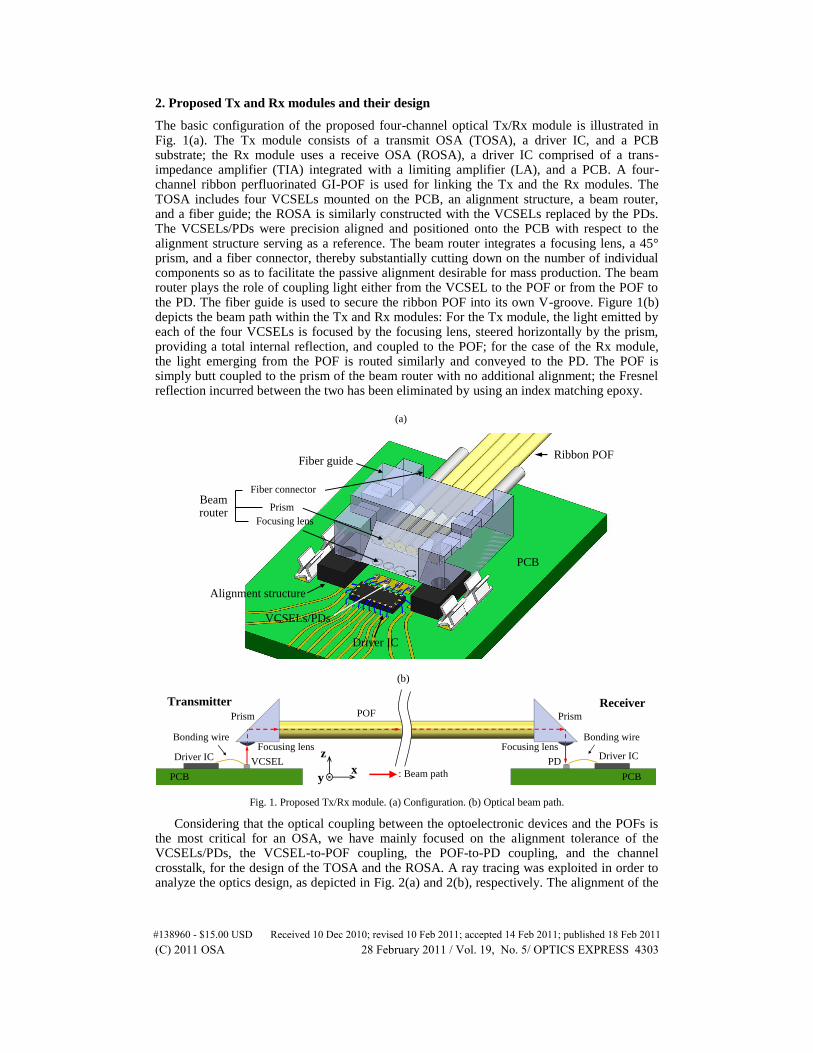
The basic configuration of the proposed four-channel optical Tx/Rx module is illustrated in Fig. 1(a). The Tx module consists of a transmit OSA (TOSA), a driver IC, and a PCB substrate; the Rx module uses a receive OSA (ROSA), a driver IC comprised of a trans-impedance amplifier (TIA) integrated with a limiting amplifier (LA), and a PCB. A four-channel ribbon perfluorinated GI-POF is used for linking the Tx and the Rx modules. The TOSA includes four VCSELs mounted on the PCB, an alignment structure, a beam router, and a fiber guide; the ROSA is similarly constructed with the VCSELs replaced by the PDs. The VCSELs/PDs were precision aligned and positioned onto the PCB with respect to the alignment structure serving as a reference. The beam router integrates a focusing lens, a 45° prism, and a fiber connector, thereby substantially cutting down on the number of individual components so as to facilitate the passive alignment desirable for mass production. The beam router plays the role of coupling light either from the VCSEL to the POF or from the POF to the PD. The fiber guide is used to secure the ribbon POF into its own V-groove. Figure 1(b) depicts the beam path within the Tx and Rx modules: For the Tx module, the light emitted by each of the four VCSELs is focused by the focusing lens, steered horizontally by the prism, providing a total internal reflection, and coupled to the POF; for the case of the Rx module, the light emerging from the POF is routed similarly and conveyed to the PD. The POF is simply butt coupled to the prism of the beam router with no additional alignment; the Fresnel reflection incurred between the two has been eliminated by using an index matching epoxy.
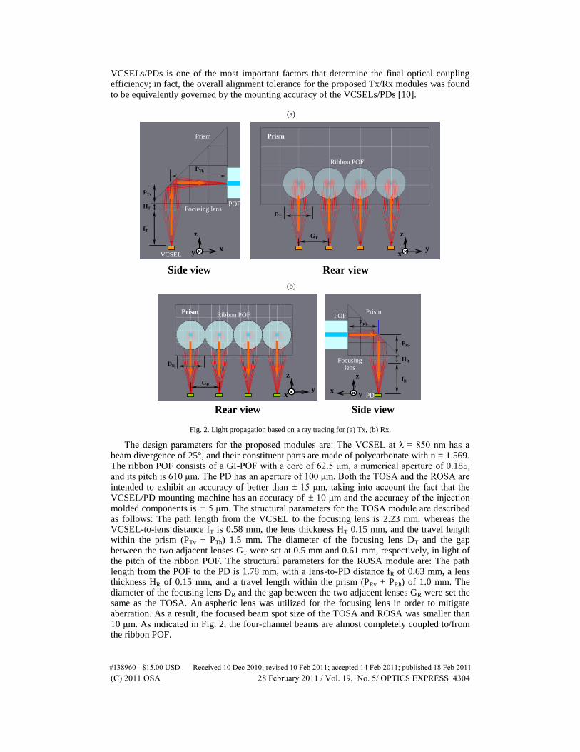
Considering that the optical coupling between the optoelectronic devices and the POFs is the most critical for an OSA, we have mainly focused on the alignment tolerance of the VCSELs/PDs, the VCSEL-to-POF coupling, the POF-to-PD coupling, and the channel crosstalk, for the design of the TOSA and the ROSA. A ray tracing was exploited in order to analyze the optics design, as depicted in Fig. 2(a) and 2(b), respectively. The alignment of the
#138960 - $15.00 USD Received 10 Dec 2010; revised 10 Feb 2011; accepted 14 Feb 2011; published 18 Feb 2011(C) 2011 OSA 28 February 2011 / Vol. 19, No. 5/ OPTICS EXPRESS 4303
VCSELs/PDs is one of the most important factors that determine the final optical coupling efficiency; in fact, the overall alignment tolerance for the proposed Tx/Rx modules was found to be equivalently governed by the mounting accuracy of the VCSELs/PDs [10].
VCSEL
POF
Prism
Focusing lens
Ribbon POF
Side view Rear view
GT
DT
HT
fT
PTv
PTh
Prism
xy
z
++ yx
z
++
PD
POFPrism
Focusing lens
Ribbon POF
Side viewRear view
GR
DR
HR
fR
PRv
PRh
Prism
yx
z
++ x y
z
++
(a)
(b)
Fig. 2. Light propagation based on a ray tracing for (a) Tx, (b) Rx.
The design parameters for the proposed modules are: The VCSEL at λ = 850 nm has a beam divergence of 25°, and their constituent parts are made of polycarbonate with n = 1.569. The ribbon POF consists of a GI-POF with a core of 62.5 μm, a numerical aperture of 0.185, and its pitch is 610 μm. The PD has an aperture of 100 μm. Both the TOSA and the ROSA are intended to exhibit an accuracy of better than 15 μm, taking into account the fact that the VCSEL/PD mounting machine has an accuracy of 10 μm and the accuracy of the injection molded components is 5 μm. The structural parameters for the TOSA module are described as follows: The path length from the VCSEL to the focusing lens is 2.23 mm, whereas the VCSEL-to-lens distance fT is 0.58 mm, the lens thickness HT 0.15 mm, and the travel length within the prism (PTv + PTh) 1.5 mm. The diameter of the focusing lens DT and the gap between the two adjacent lenses GT were set at 0.5 mm and 0.61 mm, respectively, in light of the pitch of the ribbon POF. The structural parameters for the ROSA module are: The path length from the POF to the PD is 1.78 mm, with a lens-to-PD distance fR of 0.63 mm, a lens thickness HR of 0.15 mm, and a travel length within the prism (PRv + PRh) of 1.0 mm. The diameter of the focusing lens DR and the gap between the two adjacent lenses GR were set the same as the TOSA. An aspheric lens was utilized for the focusing lens in order to mitigate aberration. As a result, the focused beam spot size of the TOSA and ROSA was smaller than 10 μm. As indicated in Fig. 2, the four-channel beams are almost completely coupled to/from the ribbon POF.
#138960 - $15.00 USD Received 10 Dec 2010; revised 10 Feb 2011; accepted 14 Feb 2011; published 18 Feb 2011(C) 2011 OSA 28 February 2011 / Vol. 19, No. 5/ OPTICS EXPRESS 4304
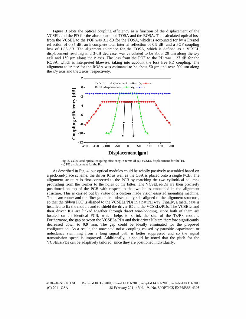
Figure 3 plots the optical coupling efficiency as a function of the displacement of the VCSEL and the PD for the aforementioned TOSA and the ROSA. The calculated optical loss from the VCSEL to the POF was 3.1 dB for the TOSA, which is accounted for by a Fresnel reflection of 0.35 dB, an incomplete total internal reflection of 0.9 dB, and a POF coupling loss of 1.85 dB. The alignment tolerance for the TOSA, which is defined as a VCSEL displacement resulting in a 3-dB decrease, was calculated to be about 20 μm along the x/y axis and 150 μm along the z axis. The loss from the POF to the PD was 1.27 dB for the ROSA, which is interpreted likewise, taking into account the loss free PD coupling. The alignment tolerance for the ROSA was estimated to be about 50 μm and over 200 μm along the x/y axis and the z axis, respectively.
-200 -150 -100 -50 0 50 100 150 200-12
-10
-8
-6
-4
-2
0
2
C
ou
pli
ng
eff
icie
ncy
[d
B]
Displacement [m]
Tx VCSEL displacement: x/y, z
Rx PD displacement: x/y, z
Fig. 3. Calculated optical coupling efficiency in terms of (a) VCSEL displacement for the Tx, (b) PD displacement for the Rx.
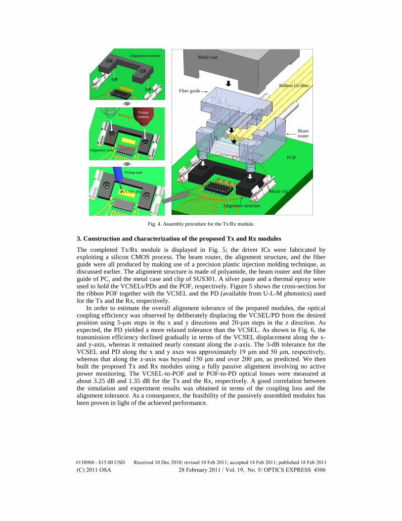
As described in Fig. 4, our optical modules could be wholly passively assembled based on a pick-and-place scheme; the driver IC as well as the OSA is placed onto a single PCB. The alignment structure is first connected to the PCB by matching the two cylindrical columns protruding from the former to the holes of the latter. The VCSELs/PDs are then precisely positioned on top of the PCB with respect to the two holes embedded in the alignment structure. This is carried out by virtue of a custom made vision-assisted mounting machine. The beam router and the fiber guide are subsequently self-aligned to the alignment structure, so that the ribbon POF is aligned to the VCSELs/PDs in a natural way. Finally, a metal case is installed to fix the module and to shield the driver IC and the VCSELs/PDs. The VCSELs and their driver ICs are linked together through direct wire-bonding, since both of them are located on an identical PCB, which helps to shrink the size of the Tx/Rx module. Furthermore, the gap between the VCSELs/PDs and their driver ICs are therefore significantly decreased down to 0.9 mm. The gap could be ideally eliminated for the proposed configuration. As a result, the unwanted noise coupling caused by parasitic capacitance or inductance stemming from a long signal path is better suppressed and so the signal transmission speed is improved. Additionally, it should be noted that the pitch for the VCSELs/PDs can be adaptively tailored, since they are positioned individually.
#138960 - $15.00 USD Received 10 Dec 2010; revised 10 Feb 2011; accepted 14 Feb 2011; published 18 Feb 2011(C) 2011 OSA 28 February 2011 / Vol. 19, No. 5/ OPTICS EXPRESS 4305
Pickup tool
Vision camera
VCSEL/PD
Alignment hole
Alignment structure
Alignment structure
Beam router
Ribbon GI-fiber
Metal case
Fiber guide
PCB
Metal clip
Fig. 4. Assembly procedure for the Tx/Rx module.
3. Construction and characterization of the proposed Tx and Rx modules
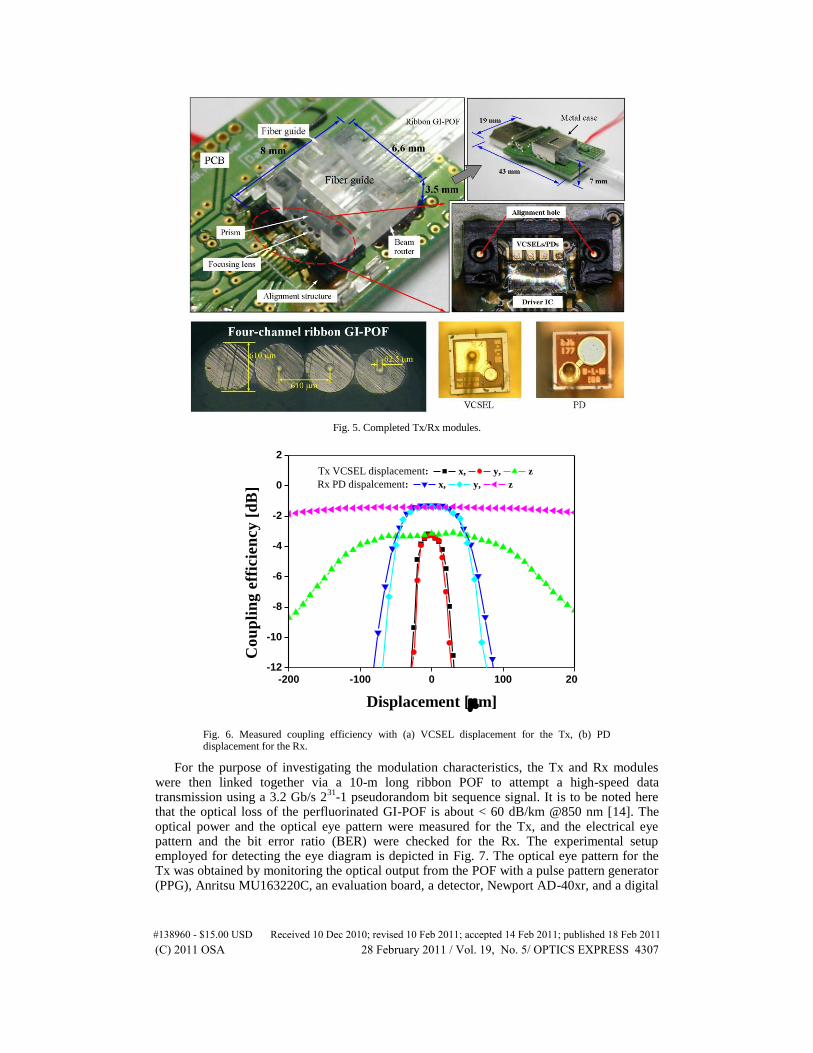
The completed Tx/Rx module is displayed in Fig. 5; the driver ICs were fabricated by exploiting a silicon CMOS process. The beam router, the alignment structure, and the fiber guide were all produced by making use of a precision plastic injection molding technique, as discussed earlier. The alignment structure is made of polyamide, the beam router and the fiber guide of PC, and the metal case and clip of SUS301. A silver paste and a thermal epoxy were used to hold the VCSELs/PDs and the POF, respectively. Figure 5 shows the cross-section for the ribbon POF together with the VCSEL and the PD (available from U-L-M photonics) used for the Tx and the Rx, respectively.
In order to estimate the overall alignment tolerance of the prepared modules, the optical coupling efficiency was observed by deliberately displacing the VCSEL/PD from the desired position using 5-μm steps in the x and y directions and 20-μm steps in the z direction. As expected, the PD yielded a more relaxed tolerance than the VCSEL. As shown in Fig. 6, the transmission efficiency declined gradually in terms of the VCSEL displacement along the x- and y-axis, whereas it remained nearly constant along the z-axis. The 3-dB tolerance for the VCSEL and PD along the x and y axes was approximately 19 μm and 50 μm, respectively, whereas that along the z-axis was beyond 150 μm and over 200 μm, as predicted. We then built the proposed Tx and Rx modules using a fully passive alignment involving no active power monitoring. The VCSEL-to-POF and te POF-to-PD optical losses were measured at about 3.25 dB and 1.35 dB for the Tx and the Rx, respectively. A good correlation between the simulation and experiment results was obtained in terms of the coupling loss and the alignment tolerance. As a consequence, the feasibility of the passively assembled modules has been proven in light of the achieved performance.
#138960 - $15.00 USD Received 10 Dec 2010; revised 10 Feb 2011; accepted 14 Feb 2011; published 18 Feb 2011(C) 2011 OSA 28 February 2011 / Vol. 19, No. 5/ OPTICS EXPRESS 4306
Fig. 5. Completed Tx/Rx modules.
-200 -100 0 100 200-12
-10
-8
-6
-4
-2
0
2
Co
up
lin
g e
ffic
ien
cy
[d
B]
Displacement [m]
Tx VCSEL displacement: x, y, z
Rx PD dispalcement: x, y, z
Fig. 6. Measured coupling efficiency with (a) VCSEL displacement for the Tx, (b) PD displacement for the Rx.
For the purpose of investigating the modulation characteristics, the Tx and Rx modules were then linked together via a 10-m long ribbon POF to attempt a high-speed data transmission using a 3.2 Gb/s 2
31-1 pseudorandom bit sequence signal. It is to be noted here
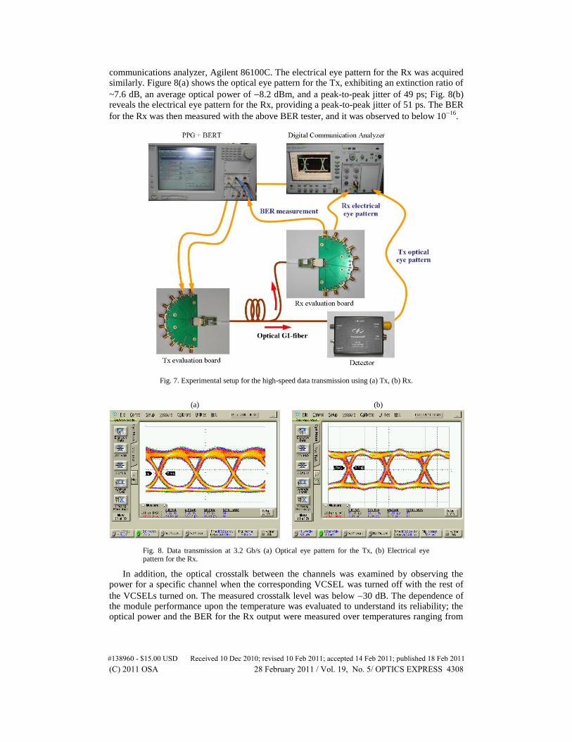
that the optical loss of the perfluorinated GI-POF is about < 60 dB/km @850 nm [14]. The optical power and the optical eye pattern were measured for the Tx, and the electrical eye pattern and the bit error ratio (BER) were checked for the Rx. The experimental setup employed for detecting the eye diagram is depicted in Fig. 7. The optical eye pattern for the Tx was obtained by monitoring the optical output from the POF with a pulse pattern generator (PPG), Anritsu MU163220C, an evaluation board, a detector, Newport AD-40xr, and a digital
#138960 - $15.00 USD Received 10 Dec 2010; revised 10 Feb 2011; accepted 14 Feb 2011; published 18 Feb 2011(C) 2011 OSA 28 February 2011 / Vol. 19, No. 5/ OPTICS EXPRESS 4307
communications analyzer, Agilent 86100C. The electrical eye pattern for the Rx was acquired similarly. Figure 8(a) shows the optical eye pattern for the Tx, exhibiting an extinction ratio of
~7.6 dB, an average optical power of 8.2 dBm, and a peak-to-peak jitter of 49 ps; Fig. 8(b) reveals the electrical eye pattern for the Rx, providing a peak-to-peak jitter of 51 ps. The BER
for the Rx was then measured with the above BER tester, and it was observed to below 1016
.
Fig. 7. Experimental setup for the high-speed data transmission using (a) Tx, (b) Rx.
(a) (b)
Fig. 8. Data transmission at 3.2 Gb/s (a) Optical eye pattern for the Tx, (b) Electrical eye pattern for the Rx.
In addition, the optical crosstalk between the channels was examined by observing the power for a specific channel when the corresponding VCSEL was turned off with the rest of
the VCSELs turned on. The measured crosstalk level was below 30 dB. The dependence of the module performance upon the temperature was evaluated to understand its reliability; the optical power and the BER for the Rx output were measured over temperatures ranging from
#138960 - $15.00 USD Received 10 Dec 2010; revised 10 Feb 2011; accepted 14 Feb 2011; published 18 Feb 2011(C) 2011 OSA 28 February 2011 / Vol. 19, No. 5/ OPTICS EXPRESS 4308
30 to 70°C with the optical module kept in a chamber. The variations in the optical power
with respect to the room temperature at 25°C were found to be less than 0.5 dB at 30°C and
2.5 dB at 70°C; an extremely low BER of less than 1016
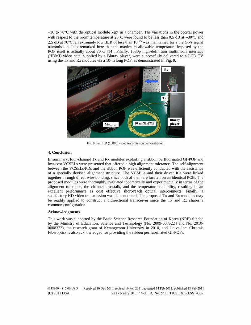
was maintained for a 3.2 Gb/s signal transmission. It is remarked here that the maximum allowable temperature imposed by the POF itself is actually about 70°C [14]. Finally, 1080p high-definition multimedia interface (HDMI) video data, supplied by a Bluray player, were successfully delivered to a LCD TV using the Tx and Rx modules via a 10-m long POF, as demonstrated in Fig. 9.
Fig. 9. Full HD (1080p) video transmission demonstration.
4. Conclusion
In summary, four-channel Tx and Rx modules exploiting a ribbon perfluorinated GI-POF and low-cost VCSELs were presented that offered a high alignment tolerance. The self-alignment between the VCSELs/PDs and the ribbon POF was efficiently conducted with the assistance of a specially devised alignment structure. The VCSELs and their driver ICs were linked together through direct wire-bonding, since both of them are located on an identical PCB. The proposed modules were thoroughly evaluated theoretically and experimentally in terms of the alignment tolerance, the channel crosstalk, and the temperature reliability, resulting in an excellent performance as cost effective short-reach optical interconnects. Finally, a satisfactory HD video transmission was demonstrated. The proposed Tx and Rx modules may be readily applied to construct a bidirectional transceiver since the Tx and Rx shares a common configuration.
Acknowledgments
This work was supported by the Basic Science Research Foundation of Korea (NRF) funded by the Ministry of Education, Science and Technology (No. 2009-0075224 and No. 2010-0008373), the research grant of Kwangwoon University in 2010, and Unive Inc. Chromis Fiberoptics is also acknowledged for providing the ribbon perfluorinated GI-POFs.
#138960 - $15.00 USD Received 10 Dec 2010; revised 10 Feb 2011; accepted 14 Feb 2011; published 18 Feb 2011(C) 2011 OSA 28 February 2011 / Vol. 19, No. 5/ OPTICS EXPRESS 4309