26
Richard E. Goodman, (A personal perspective)
| Date post: | 25-Dec-2015 |
| Category: |
Documents |
| Upload: | victoria-gibbs |
| View: | 219 times |
| Download: | 0 times |
Richard E. Goodman,(A personal perspective)
1. Discovery of finite element analysis by the rock mechanics community.
2. Improvements in fea and finite difference methods for non-elastic, and plastic materials & explicit methods for following dynamic, or large strain failure trajectories (e.g. complete stress/strain curves of failing rock pillars).
3. Adaptation of finite element analysis for jointed rock with introduction of joint elements (leading to general contact elements used in medicine, rocket design, earth dam analysis, etc etc etc); sometimes leading to over-expectation of quick improvements in rock engineering.
4. Growing disenchantment with traditional continuum mechanics - - but perseverance in certain problem areas, e.g. fluid flow and mechanics of uniformly porous and pervious reservoir rocks; and mine layouts in uniform elastic, effectively continuous formations with significant in situ stress.
5. Developing interest in rock mass classification and exaggerated expectations that, with their use, the input needs of large, complex computations will be satisfactorily met.
(Most promising is Hoek-Brown rock mass strength approach with various hooks (Hoeks) and handles - - but how to be certain of the choices made for the various values?)
6. Recognition and development of discontinuum mechanics for blocky rock masses controlled by geological structure, with special tools and particular modes of behavior.
Base friction models provide insight into deformation and cracking of excavations cut in jointed rock; they highlight a variety of previously neglected beam and block failure modes, rotational modes, and combined rotation and toppling, which involve sliding, and opening of joints and growth of flexural, and tensile cracks.
These failure modes are subsequently borne out in precise detail in practice, and duplicated in analytical models with reduced degrees of freedom (UDEC and DDA) simulating large systems of rigid materials and geological constraints. Particle flow code (Cundall) follows.
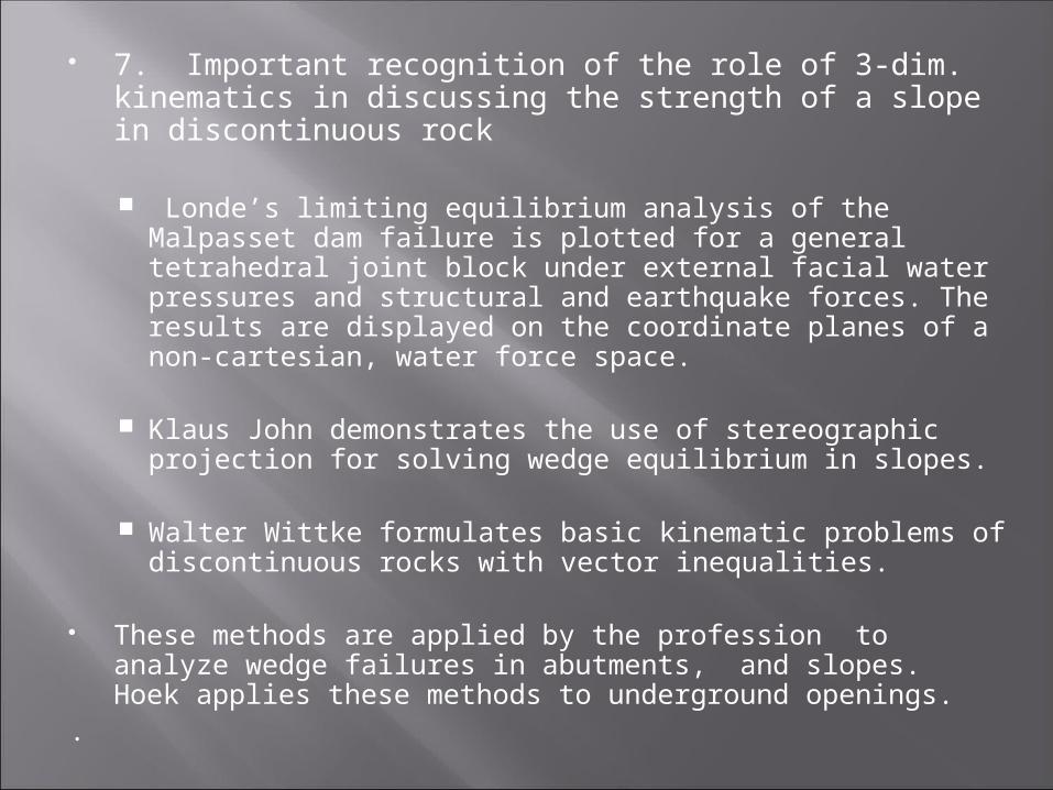
7. Important recognition of the role of 3-dim. kinematics in discussing the strength of a slope in discontinuous rock
Londe’s limiting equilibrium analysis of the Malpasset dam failure is plotted for a general tetrahedral joint block under external facial water pressures and structural and earthquake forces. The results are displayed on the coordinate planes of a non-cartesian, water force space.
Klaus John demonstrates the use of stereographic
projection for solving wedge equilibrium in slopes.
Walter Wittke formulates basic kinematic problems of discontinuous rocks with vector inequalities.
These methods are applied by the profession to analyze wedge failures in abutments, and slopes. Hoek applies these methods to underground openings.
.
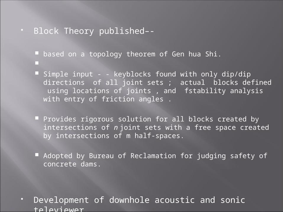
Block Theory published–-
based on a topology theorem of Gen hua Shi. Simple input - - keyblocks found with only dip/dip directions of
all joint sets ; actual blocks defined using locations of joints , and fstability analysis with entry of friction angles .
Provides rigorous solution for all blocks created by intersections of n joint sets with a free space created by intersections of m half-spaces.
Adopted by Bureau of Reclamation for judging safety of concrete dams.
Development of downhole acoustic and sonic televiewer. Provides absolute orientation of discontinuities and more.
Incredible advances in computational technologycomputer speed, power, storage, availability; CAD (computer aided design): Auto Cad Google Earth and Sketch-UpLidar imagery : remote measurement of dip/dip direction & roughnessAdvanced terrestrial photogrammetry
Dynamic analysis advance - using new “seismo-tectonics”
Advances in geophysics using probabilistic inverse theory
and finite element like models
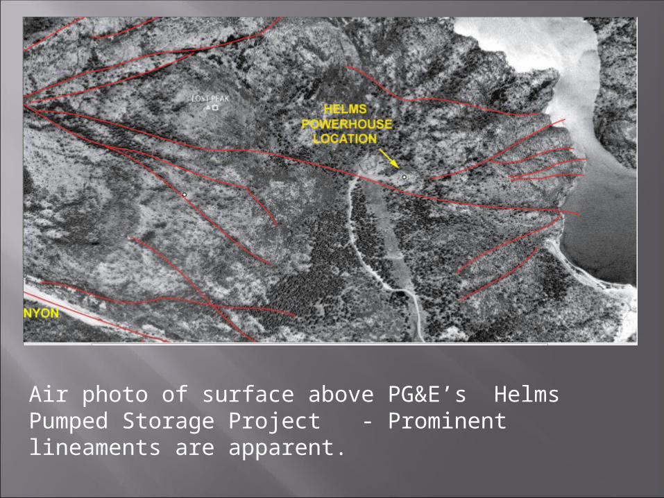
Air photo of surface above PG&E’s Helms Pumped Storage Project - Prominent lineaments are apparent.
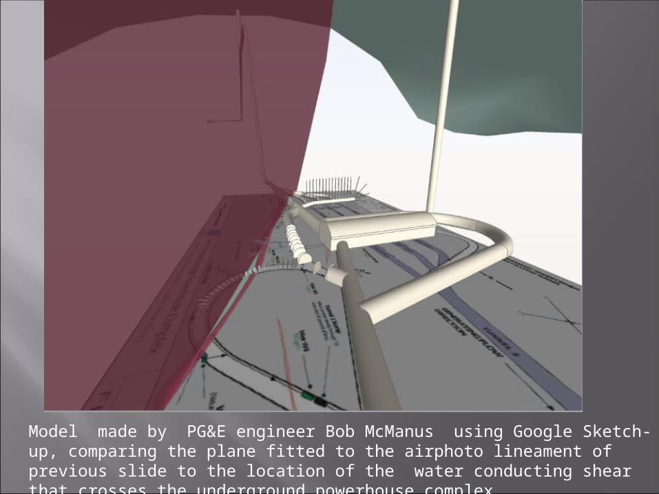
Model made by PG&E engineer Bob McManus using Google Sketch-up, comparing the plane fitted to the airphoto lineament of previous slide to the location of the water conducting shear that crosses the underground powerhouse complex.
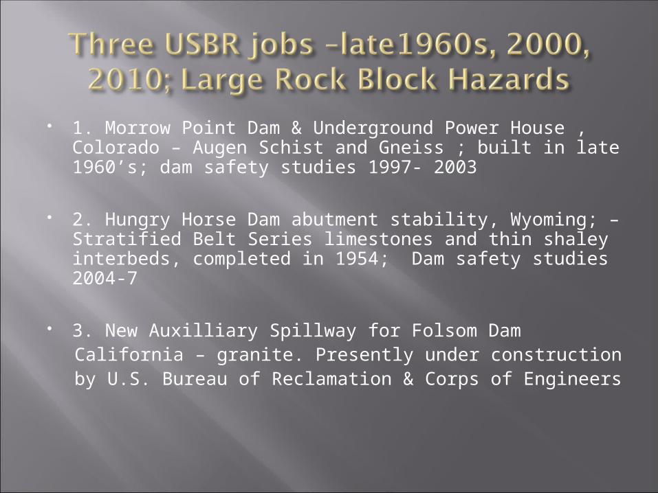
1. Morrow Point Dam & Underground Power House , Colorado – Augen Schist and Gneiss ; built in late 1960’s; dam safety studies 1997- 2003
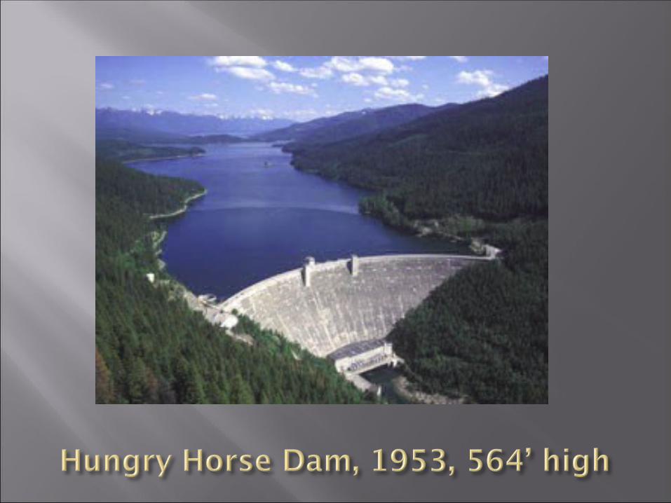
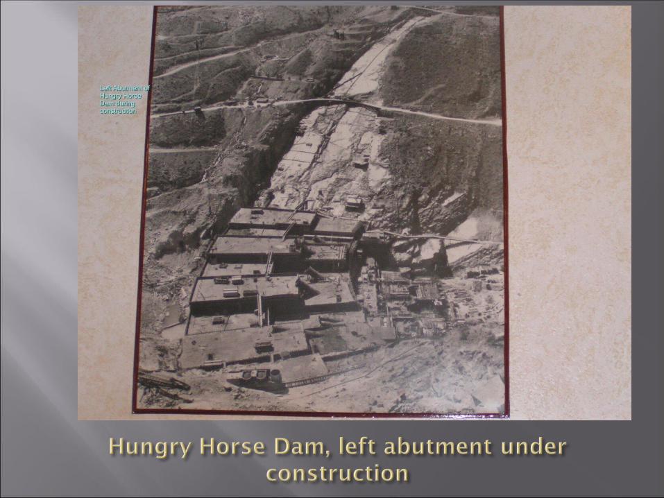
2. Hungry Horse Dam abutment stability, Wyoming; – Stratified Belt Series limestones and thin shaley interbeds, completed in 1954; Dam safety studies 2004-7
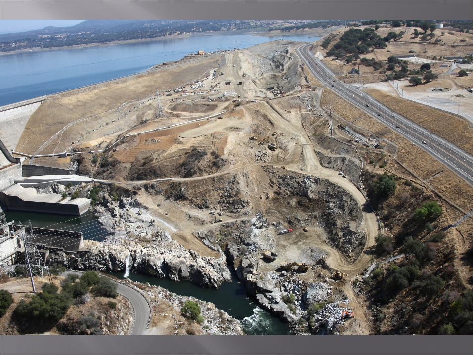
3. New Auxilliary Spillway for Folsom DamCalifornia – granite. Presently under construction by U.S. Bureau of Reclamation & Corps of Engineers
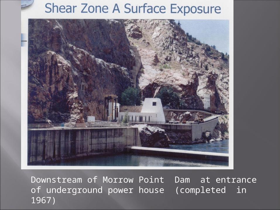
Downstream of Morrow Point Dam at entrance of underground power house (completed in 1967)
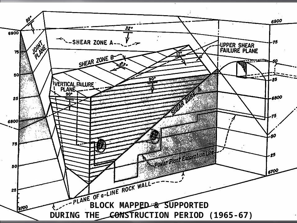
BLOCK MAPPED & SUPPORTEDDURING THE CONSTRUCTION PERIOD (1965-67)
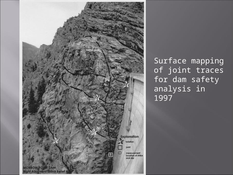
Surface mapping of joint traces for dam safety analysis in 1997
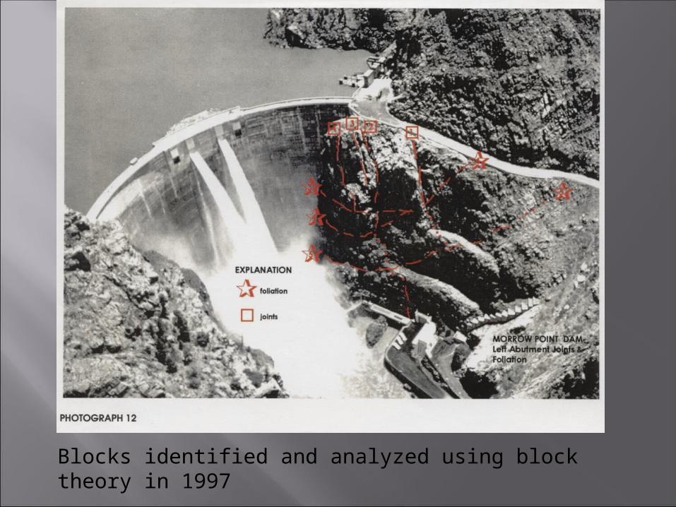
Blocks identified and analyzed using block theory in 1997
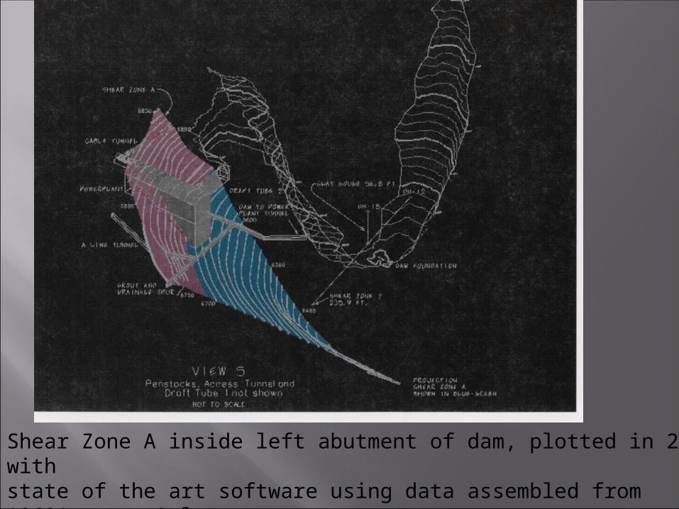
Shear Zone A inside left abutment of dam, plotted in 2003 with state of the art software using data assembled from 1960’s maps & logs
19
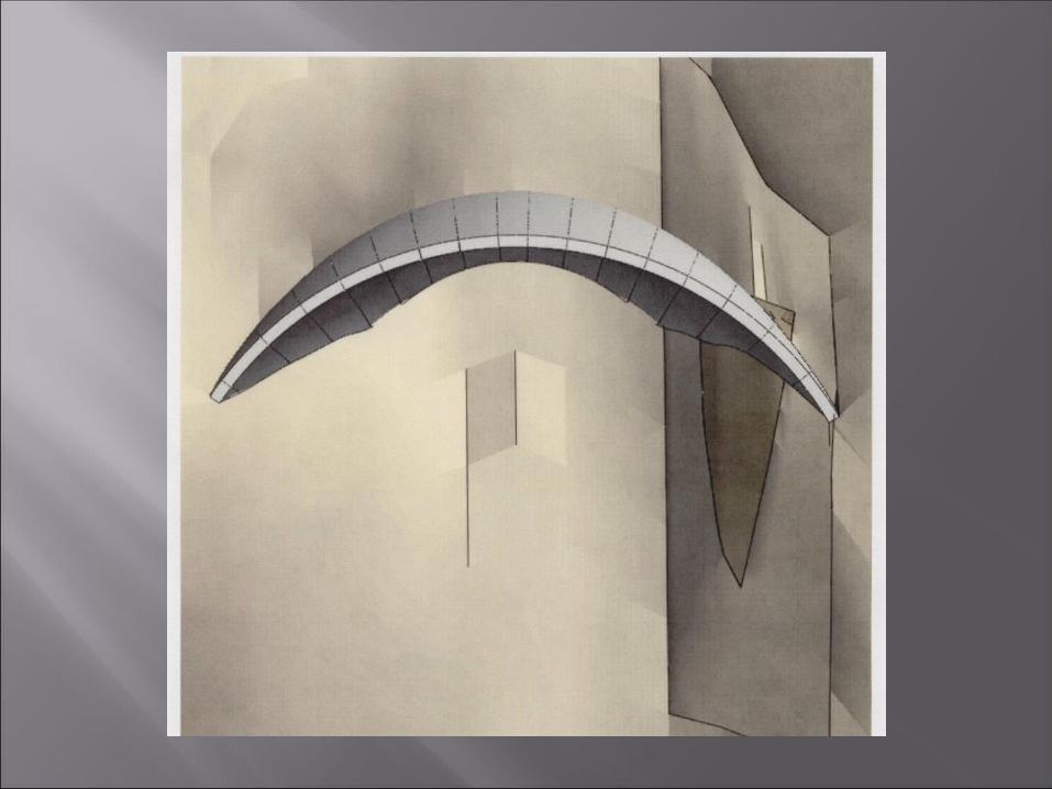
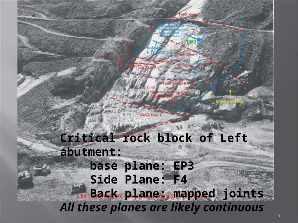
Critical rock block of Left abutment:
base plane: EP3 Side Plane: F4 Back plane: mapped jointsAll these planes are likely continuous
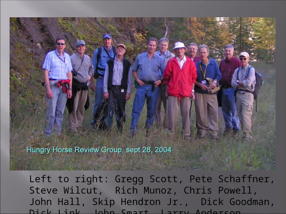
Left to right: Gregg Scott, Pete Schaffner, Steve Wilcut, Rich Munoz, Chris Powell, John Hall, Skip Hendron Jr., Dick Goodman, Dick Link, John Smart, Larry Anderson
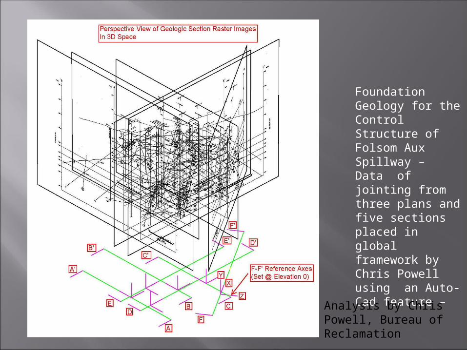
Foundation Geology for the Control Structure of Folsom Aux Spillway – Data of jointing from three plans and five sections placed in global framework by Chris Powell using an Auto-Cad feature –
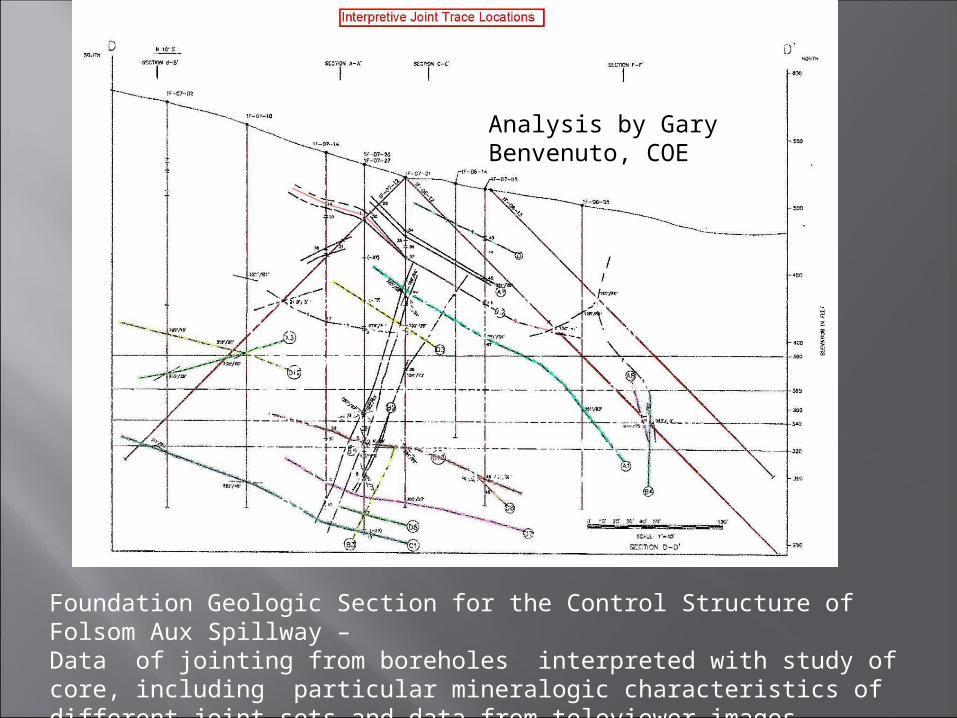
Foundation Geologic Section for the Control Structure of Folsom Aux Spillway – Data of jointing from boreholes interpreted with study of core, including particular mineralogic characteristics of different joint sets and data from televiewer images.
Analysis by Gary Benvenuto, COE
Foundation Geology for the Control Structure of Folsom Aux Spillway – Data of jointing from three plans and five sections placed in global framework by Chris Powell using an Auto-Cad feature –
Analysis by Chris Powell, Bureau of Reclamation
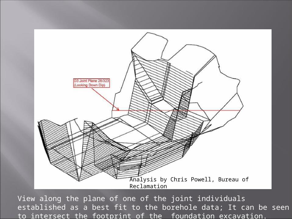
View along the plane of one of the joint individuals established as a best fit to the borehole data; It can be seen to intersect the footprint of the foundation excavation.
Analysis by Chris Powell, Bureau of Reclamation
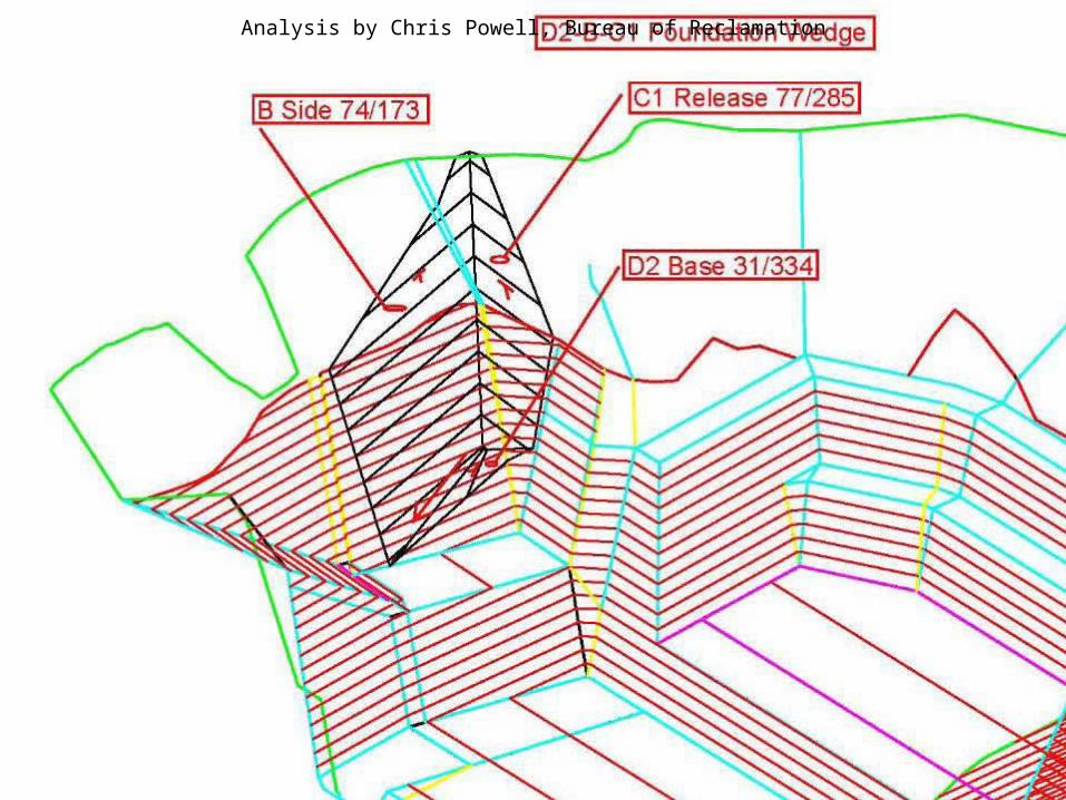
Analysis by Chris Powell, Bureau of Reclamation
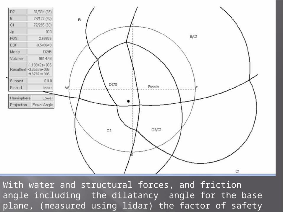
With water and structural forces, and friction angle including the dilatancy angle for the base plane, (measured using lidar) the factor of safety for this block is 2.7 (using Pantechnica PT Workshop).


