124
Model TITANIUM3 Machine Code: C274 Field Service Manual March 2009 Subject to change
| Date post: | 03-Jan-2016 |
| Category: |
Documents |
| Upload: | amer-rafique |
| View: | 250 times |
| Download: | 2 times |

Model TITANIUM3
Machine Code: C274
Field Service Manual
March 2009
Subject to change


Important Safety Notices
Responsibilities of the Customer Engineer
Customer Engineer
Maintenance shall be done only by trained customer engineers who have completed service training forthe machine and all optional devices designed for use with the machine.
Reference Material for Maintenance
• Maintenance shall be done using the special tools and procedures prescribed for maintenance of themachine described in the reference materials (service manuals, technical bulletins, operatinginstructions, and safety guidelines for customer engineers).
• In regard to other safety issues not described in this document, all customer engineers shall strictlyobey procedures and recommendations described the "CE Safety Guide".
• Use only consumable supplies and replacement parts designed for use of the machine.
Before Installation, Maintenance
Shipping and Moving the Machine
• Work carefully when lifting or moving the machine. If the machine is heavy, two or more customerengineers may be required to prevent injuries (muscle strains, spinal injuries, etc.) or damage tothe machine if it is dropped or tipped over.
• Personnel moving or working around the machine should always wear proper clothing andfootwear. Never wear loose fitting clothing or accessories (neckties, loose sweaters, bracelets,etc.) or casual footwear (slippers, sandals, etc.) when lifting or moving the machine.
• Always unplug the power cord from the power source before you move the product. Before youmove the product, arrange the power cord so it will not fall under the product.
Power
• Always disconnect the power plug before doing any maintenance procedure. After switchingoff the machine, power is still supplied to the main machine and other devices. To prevent
1

electrical shock, switch the machine off, wait for a few seconds, then unplug the machine fromthe power source.
• Before you do any checks or adjustments after turning the machine off, work carefully to avoidinjury. After removing covers or opening the machine to do checks or adjustments, never touchelectrical components or moving parts (gears, timing belts, etc.).
• After turning the machine on with any cover removed, keep your hands away from electricalcomponents and moving parts. Never touch the cover of the fusing unit, gears, timing belts, etc.
Installation, Disassembly, and Adjustments
• After installation, maintenance, or adjustment, always check the operation of the machine tomake sure that it is operating normally. This ensures that all shipping materials, protectivematerials, wires and tags, metal brackets, etc., removed for installation, have been removedand that no tools remain inside the machine. This also ensures that all release interlock switcheshave been restored to normal operation.
• Never use your fingers to check moving parts causing spurious noise. Never use your fingers tolubricate moving parts while the machine is operating.
Special Tools
• Use only standard tools approved for machine maintenance.
• For special adjustments, use only the special tools and lubricants described in the service manual.Using tools incorrectly, or using tools that could damage parts, could damage the machine orcause injuries.
During Maintenance
General
• Before you begin a maintenance procedure: 1) Switch the machine off, 2) Disconnect the power plugfrom the power source.
2

Safety Devices
• Never remove any safety device unless it requires replacement. Always replace safety devicesimmediately.
• Never do any procedure that defeats the function of any safety device. Modification or removalof a safety device (fuse, switch, etc.) could lead to a fire and personal injury. Always test theoperation of the machine to ensure that it is operating normally and safely after removal andreplacement of any safety device.
• For replacements use only the correct fuses or circuit breakers rated for use with the machine.Using replacement devices not designed for use with the machine could lead to a fire andpersonal injuries.
Organic Cleaners
• During preventive maintenance, never use any organic cleaners (alcohol, etc.) other than thosedescribed in the service manual.
• Make sure the room is well ventilated before using any organic cleaner. Use organic solventsin small amounts to avoid breathing the fumes and becoming nauseous.
• Switch the machine off, unplug it, and allow it to cool before doing preventive maintenance. Toavoid fire or explosion, never use an organic cleaner near any part that generates heat.
• Wash your hands thoroughly after cleaning parts with an organic cleaner to contamination offood, drinks, etc. which could cause illness.
• Clean the floor completely after accidental spillage of silicone oil or other materials to preventslippery surfaces that could cause accidents leading to hand or leg injuries. Use "My Ace"Silicone Oil Remover (or dry rags) to soak up spills. For more details, please refer to TechnicalBulletin "Silicone Oil Removal" (A024-50).
Power Plug and Power Cord
• Before serving the machine (especially when responding to a service call), always make surethat the power plug has been inserted completely into the power source. A partially insertedplug could lead to heat generation (due to a power surge caused by high resistance) and causea fire or other problems.
• Always check the power plug and make sure that it is free of dust and lint. Clean it if necessary.A dirty plug can generate heat which could cause a fire.
3

• Inspect the length of the power cord for cuts or other damage. Replace the power cord ifnecessary. A frayed or otherwise damaged power cord can cause a short circuit which couldlead to a fire or personal injury from electrical shock.
• Check the length of the power cord between the machine and power supply. Make sure thepower cord is not coiled or wrapped around any object such as a table leg. Coiling the powercord can cause excessive heat to build up and could cause a fire.
• Make sure that the area around the power source is free of obstacles so the power cord can beremoved quickly in case of an emergency.
• Make sure that the power cord is grounded (earthed) at the power source with the ground wireon the plug.
• Connect the power cord directly into the power source. Never use an extension cord.
• When you disconnect the power plug from the power source, always pull on the plug, not thecable.
After Installation, Servicing
Points to Confirm with Operators
At the end of installation or a service call, instruct the user about use of the machine. Emphasize the followingpoints.
• Show operators how to remove jammed paper and troubleshoot other minor problems by followingthe procedures described in the operating instructions.
• Point out the parts inside the machine that they should never touch or attempt to remove.
• Confirm that operators know how to store and dispose of consumables.
• Make sure that all operators have access to an operating instruction manual for the machine.
• Confirm that operators have read and understand all the safety instructions described in the operatinginstructions.
• Demonstrate how to turn off the power and disconnect the power plug (by pulling the plug, not thecord) if any of the following events occur: 1) something has spilled into the product, 2) service orrepair of the product is necessary, 3) the product cover has been damaged.
• Caution operators about removing paper fasteners around the machine. They should never allowpaper clips, staples, or any other small metallic objects to fall into the machine.
4

Safety Instructions for this Machine
Prevention of Physical Injury
1. Before disassembling or assembling parts of the machine and peripherals, make sure that the machineand peripheral power cords are unplugged.
2. The plug should be near the machine and easily accessible.
3. If any adjustment or operation check has to be made with exterior covers off or open while the mainswitch is turned on, keep hands away from electrified or mechanically driven components.
4. The inside and the metal parts of the fusing unit become extremely hot while the machine is operating.Be careful to avoid touching those components with your bare hands.
5. To prevent a fire or explosion, keep the machine away from flammable liquids, gases, and aerosols.
Health Safety Conditions
1. If you get ink in your eyes by accident, try to remove it with eye drops or flush with water as first aid.If unsuccessful, get medical attention.
2. If you ingest ink by accident, induce vomiting by sticking a finger down your throat or by giving soapyor strong salty water to drink.
Observance of Electrical Safety Standards
1. The machine and its peripherals must be installed and maintained by a customer service representativewho has completed the training course on those models.
Safety and Ecological Notes for Disposal
1. Dispose of replaced parts in accordance with local regulations.
2. Used ink and masters should be disposed of in an environmentally safe manner and in accordancewith local regulations.
Symbols
This manual uses several symbols. The meanings of those symbols are as follows:
* See or Refer to
L Core tech manual
5

c Clip ring
e E-ring
Screw
Connector
6

TABLE OF CONTENTSImportant Safety Notices...................................................................................................................................1
Responsibilities of the Customer Engineer....................................................................................................1
Before Installation, Maintenance..................................................................................................................1
During Maintenance......................................................................................................................................2
After Installation, Servicing............................................................................................................................4
Safety Instructions for this Machine...............................................................................................................5
Symbols...........................................................................................................................................................5
1. Product Information
Specifications....................................................................................................................................................11
Mechanism Overview......................................................................................................................................12
Component Layout.......................................................................................................................................12
Electrical Component Layout......................................................................................................................13
Drive Layout..................................................................................................................................................17
Guidance for Those Who are Familiar with Predecessor Products..............................................................18
2. Installation
Installation Requirements.................................................................................................................................19
Optimum Environmental Condition............................................................................................................19
Environments to Avoid.................................................................................................................................19
Power Connection.......................................................................................................................................19
Machine Access...........................................................................................................................................19
Installation Procedure......................................................................................................................................21
Main Unit......................................................................................................................................................21
Optional Installation.........................................................................................................................................31
Additional Drums.........................................................................................................................................31
Printer Unit VC-20 and Interface Board Type 20.....................................................................................32
3. Preventive Maintenance
Maintenance Tables........................................................................................................................................37
4. Replacement and Adjustment
General Caution...............................................................................................................................................39
Special Tools....................................................................................................................................................40
Image Adjustment.............................................................................................................................................41
SP6-42: Image Adjustment Pattern Print....................................................................................................41
DIP Switches.................................................................................................................................................42
7

DIPSW103 No.5 to 8 – Master Feeding Speed Adjustment..................................................................43
DIPSW101 No.1 to 4 – Paper Registration Position Adjustment............................................................44
DIPSW101 No.5 to 8 – Master Writing Position Adjustment.................................................................45
DIPSW102 No.1 to 3 – Thermal Head Energy Control..........................................................................47
DIPSW103 No.1 to 4 – Scanning Speed Adjustment.............................................................................47
Covers and Boards..........................................................................................................................................49
Front Cover, Operation Panel....................................................................................................................49
Rear Cover...................................................................................................................................................50
MPU..............................................................................................................................................................50
PSU................................................................................................................................................................51
Scanner.............................................................................................................................................................52
Covers...........................................................................................................................................................52
1st and 2nd Feed Rollers, CIS (Contact Image Sensor)...........................................................................53
Document Sensor.........................................................................................................................................54
Scanner Motor.............................................................................................................................................54
Master Feed......................................................................................................................................................55
Master Making Unit.....................................................................................................................................55
Thermal Head..............................................................................................................................................56
Thermal Head Voltage Adjustment.............................................................................................................57
Master End Sensor Adjustment...................................................................................................................58
Master Eject......................................................................................................................................................60
Master Eject Unit..........................................................................................................................................60
Master Eject Rollers.....................................................................................................................................60
Paper Feed........................................................................................................................................................62
Paper Feed Roller / Friction Pad................................................................................................................62
Paper Feed Pressure Adjustment.................................................................................................................62
Paper Separation Pressure Adjustment......................................................................................................63
Printing...............................................................................................................................................................67
Press Roller...................................................................................................................................................67
Paper Registration Roller.............................................................................................................................68
Press Roller Release Lever Adjustment........................................................................................................69
Printing Pressure Adjustment........................................................................................................................71
Drum..................................................................................................................................................................72
8

Preparation...................................................................................................................................................72
Cloth Screen.................................................................................................................................................72
Clamper / Metal Screen............................................................................................................................75
Ink Pump Unit................................................................................................................................................77
Ink Roller Unit / Ink Roller One Way Clutch.............................................................................................78
Doctor Roller Gap Adjustment....................................................................................................................79
Ink Detection Adjustment.............................................................................................................................81
Paper Delivery..................................................................................................................................................82
Paper Delivery Unit......................................................................................................................................82
Delivery Belt / Paper Exit Sensor...............................................................................................................83
Exit Pawl Adjustment....................................................................................................................................84
Main Drive .......................................................................................................................................................88
Main Drive Timing Belt Adjustment.............................................................................................................88
Main Motor Pulley Position.........................................................................................................................88
Firmware Update.............................................................................................................................................90
5. System Maintenance Reference
Service Program Mode....................................................................................................................................91
SP Tables......................................................................................................................................................91
Using Service Program Modes...................................................................................................................91
Using the SP Mode......................................................................................................................................92
6. Troubleshooting
Service Call Conditions...................................................................................................................................93
Electrical Component Defects.........................................................................................................................94
Fuse, LED, VR, DIP-SW, AND TP Tables........................................................................................................95
9

10

1. Product Information
SpecificationsSee "Appendices" for the following information:
• General specifications
11
1
Mechanism Overview
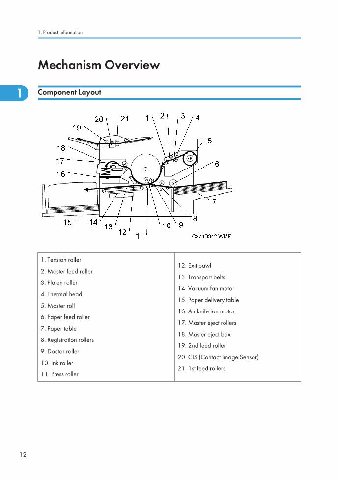
Component Layout
1. Tension roller
2. Master feed roller
3. Platen roller
4. Thermal head
5. Master roll
6. Paper feed roller
7. Paper table
8. Registration rollers
9. Doctor roller
10. Ink roller
11. Press roller
12. Exit pawl
13. Transport belts
14. Vacuum fan motor
15. Paper delivery table
16. Air knife fan motor
17. Master eject rollers
18. Master eject box
19. 2nd feed roller
20. CIS (Contact Image Sensor)
21. 1st feed rollers
1. Product Information
12
1
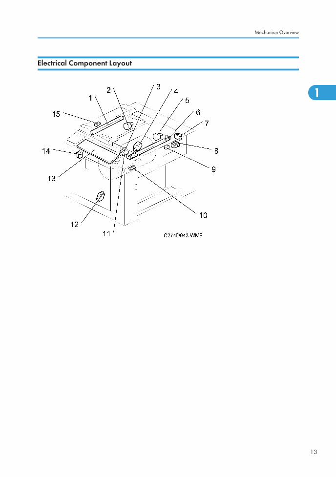
Electrical Component Layout
Mechanism Overview
13
1

Boards
No. Component Function
13 Operation Panel Board This board controls the operation panel.
34 Main Processing Unit (MPU)Controls all machine functions, both directly and through otherboards.
37 Power Supply Unit (PSU) Provides dc power to the machine.
Motors
No. Component Function
2 Scanner Motor Drives the scanner.
4 Ink Pump Motor Drives the ink pump.
5 Master Feed Motor Feeds the master to the drum.
11 Cutter Motor Cuts the master.
1. Product Information
14
1

No. Component Function
22 Master Eject Motor used masters into the master eject box.
23 Air Knife Fan MotorRotates the fan to provide air to separate the leading edge ofthe paper from the drum.
26 Vacuum Fan MotorProvides suction so that paper is held firmly on the transportbelt.
27 Pressure Plate Motor Drives the pressure plate.
29 Clamper Motor Opens or closes the master clamper on the drum.
31 Main Motor Rotates the drum, paper feed roller and transport belts.
33 Registration Motor Feeds the paper to align it with the master on the drum.
Switches
No. Component Function
7 Right Side Cover Set Switch Checks if the right side cover is closed.
14 Door Safety Switch Checks whether the front door is properly closed.
Solenoids
No. Component Function
12Front Pressure ReleaseSolenoid
Releases the press roller to apply printing pressure.
30Rear Pressure ReleaseSolenoid
Releases the press roller to apply printing pressure.
Counters
No. Component Function
20 Master Counter Keeps track of the total number of masters made.
21 Paper Counter Keeps track of the total number of copies.
Sensors
No. Component Function
3 Cutter HP Sensor Detects when the cutter is at the home position.
Mechanism Overview
15
1

No. Component Function
8 Master Set Cover Sensor Checks if the master set cover is properly set.
9 Master End Sensor Detects when the master making unit runs out of master roll.
10 Registration Sensor Detects paper approaching the registration roller.
15Document Sensor Detects the leading edge of the original to determine when to
turn off the scanner motor. Checks for original misfeeds.
16 Pressure Plate HP Sensor Detects when the pressure plate is at the home position.
17 Pressure Plate Limit Sensor Detects when the pressure plate is in the lowest position.
18 Master Eject Sensor Detects used master misfeeds.
19 Drum Master Sensor Detects if there is a master on the drum.
24 Eject Box Set Sensor Checks if the master eject box is installed.
25 Paper Exit Sensor Detects paper misfeeds at the exit.
28 Clamper Open Sensor Detects if the clamper is in the open position.
32 Feed Start Timing Sensor Determines the paper feed start timing.
36 Clamper Closed Sensor Detects if the clamper is in the closed position.
38MasterEject Position (DrumHP) Sensor
Detects when the drum is at the master eject position.
Others
No. Component Function
1Contact Image Sensor (CIS) This sensor reads and converts the light reflected from the
document into an analog video signal.
6 Thermal Head Burns the image onto the master.
35Paper Feed Clutch Transmits main motor drive to the paper feed rollers at the
appropriate time.
1. Product Information
16
1
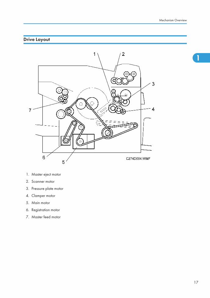
Drive Layout
1. Master eject motor
2. Scanner motor
3. Pressure plate motor
4. Clamper motor
5. Main motor
6. Registration motor
7. Master feed motor
Mechanism Overview
17
1

Guidance for Those Who are Familiar withPredecessor ProductsMachine C274 is a successor model to Machine C261. If you have experience with the predecessorproducts, the following information will be of help when you read this manual.
Different Points from Predecessor Products
C274 C261
Drum pump adjustment No *1 Yes
• *1 This model uses the trochoid pump unit that is used in the C267 series.
1. Product Information
18
1

2. Installation
Installation RequirementsCarefully select the installation location because environmental conditions greatly affect machineperformance.
Optimum Environmental Condition
1. Temperature: 10 to 30 °C (50 to 86 °F)
2. Humidity: 20 to 90 %RH
3. Install the machine on a strong and level base. The machine must be level within 5mm (0.2") bothfront to rear left to right.
Environments to Avoid
1. Locations exposed to direct sunlight or strong light (more than 1,500 lux).
2. Dusty areas
3. Areas containing corrosive gases.
4. Locations directly exposed to cool air from an air conditioner or reflected heat from a space heater.(Sudden temperature changes from low to high or vice versa may cause condensation within themachine.)
Power Connection
1. Securely connect the power cord to a power source.
2. Make sure that the wall outlet is near the machine and easily accessible.
3. Make sure the plug is firmly inserted in the outlet.
4. Avoid multi-wiring
5. Do not pinch the power cord.
Machine Access
Place the machine near a power source, providing minimum clearance as shown below.
19
2

Dimensions
2. Installation
20
2
Installation Procedure
Main Unit
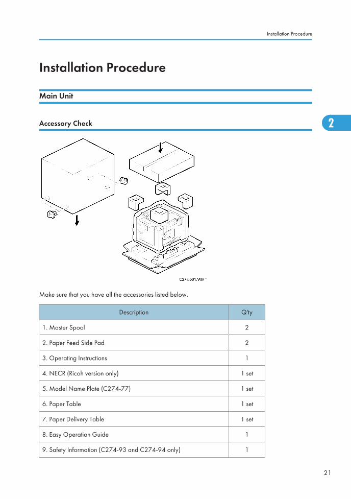
Accessory Check
Make sure that you have all the accessories listed below.
Description Q'ty
1. Master Spool 2
2. Paper Feed Side Pad 2
3. Operating Instructions 1
4. NECR (Ricoh version only) 1 set
5. Model Name Plate (C274-77) 1 set
6. Paper Table 1 set
7. Paper Delivery Table 1 set
8. Easy Operation Guide 1
9. Safety Information (C274-93 and C274-94 only) 1
Installation Procedure
21
2

Description Q'ty
10. Bundled Items List (C274-76 and C274-78 only) 1
Installation Procedure
• To avoid serious injury, do not connect the power plug to the machine until you are instructed to doso.
2. Installation
22
2

1. Unpack the machine and remove all the wrapping.
2. Remove all filament tape and string securing the covers and units as shown above.
3. Remove the front tape [A], the tag [B], and the rear tape [C].
• To remove the rear tape, pull the portion shown in the diagram toward the front of themachine.These tapes were also used in the Titanium2 (C261).
Installation Procedure
23
2

4. Open the right side cover, and take out the accessory bag [D].
5. Insert both spools into a new master roll.
6. Install the master roll.
2. Installation
24
2

7. Open the master making unit cover, and insert the leading edge of the master roll under the platenroller. The arrows [E] indicate the correct position of the master leading edge.
• The leading edge of the master does not enter the interior of the master making unit, becausethe part at the arrows [E] is convex.
8. Close the master making unit cover [F] using both hands until it clicks into place.
9. Close the right side cover.
Installation Procedure
25
2

10. Open the front door.
11. Release the ink holder lock lever [G] and pull out the ink holder [H].
12. Insert a new ink cartridge.
13. Take the paper table and paper delivery table out of the box.
2. Installation
26
2

14. Lower the paper feed tray adjustment lever [I], and install the paper table.( x 2)
• When installing the paper table, make sure that the hooks [J] are set firmly.
• Two side fence friction pads are included as accessories. They are not used normally, but ifpaper multi-feed frequently occurs or thin paper is used, the side fence friction pads can beinstalled to apply stopping pressure to the paper.
15. Attach the side and end fences, as shown. ( x 3)
Installation Procedure
27
2
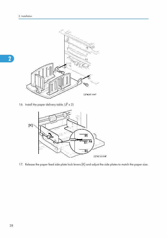
16. Install the paper delivery table. ( x 2)
17. Release the paper feed side plate lock levers [K] and adjust the side plates to match the paper size.
2. Installation
28
2

18. Load paper into the paper table.
19. Shift the paper feed tray adjustment lever [I] up to the paper feeding position.
20. Adjust the side and end fences of the paper delivery table to match the paper size.
Installation Procedure
29
2

21. Attach the original table [L].
22. Firmly insert the power plug in the outlet.
23. Turn on the main switch.
24. Press the clear/stop key while holding down the 0 key, to supply ink to the drum.
25. Make some test copies.
2. Installation
30
2

Optional Installation
Additional Drums
There are two types of drum units:
B4 size Color Drum: Color Drum Type 20 (M)
LG size Color Drum: Color Drum Type 20 (S)
1. Remove the protective sheet [A] from the drum unit.
2. Attach a color indicator decal to the drum case. The decal must be the same color as the ink in use.
Optional Installation
31
2

3. Remove the drum unit.
4. Leave the master wrapped around the removed drum to protect the drum from dust and from drying.
5. Keep the removed drum unit in the drum case.
6. Install the drum unit.
7. Remove the ink cartridge cap.
8. Insert the ink cartridge in the ink holder.
Printer Unit VC-20 and Interface Board Type 20
• The Interface board type 20 must be installed before you install the Printer Unit VC-20.
Accessory Check (Interface Board Type 20)
Check the quantity and condition of the accessories in the box against the following list:
Description Q'ty
1. Interface Board 1
2. Interface Cable 1
3. Bracket 2
4. Screw M3x6 6
Accessory Check (Printer Unit VC-20)
Check the quantity and condition of the accessories in the box against the following list:
2. Installation
32
2
Description Q'ty
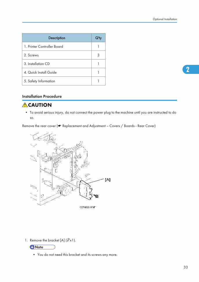
1. Printer Controller Board 1
2. Screws 3
3. Installation CD 1
4. Quick Install Guide 1
5. Safety Information 1
Installation Procedure
• To avoid serious injury, do not connect the power plug to the machine until you are instructed to doso.
Remove the rear cover (* Replacement and Adjustment – Covers / Boards - Rear Cover)
1. Remove the bracket [A] (x1).
• You do not need this bracket and its screws any more.
Optional Installation
33
2

1. Attach the printer controller board [E] to the bracket [B] (x4).
2. Attach the bracket [C] to the bracket [B] (x2).
3. Connect the connector [D] to the socket on the right side of the board [E].
• Make sure that the connector is securely connected to the socket.
2. Installation
34
2

4. Attach the bracket assembly [F] to the same place that the bracket [A] (Step 1) was installed (1 screw).
• In this step, only use the M3x6 screw included with the Interface board Type 20.
5. Connect the socket [J] on the interface board to CN108 [K] on the MPU [L].
• Make sure that the socket is securely connected to CN108.
6. Connect the connector [H] to the socket [G] on the interface board.
7. Attach the interface board [I] to the bracket assembly [F] (x 2).
Optional Installation
35
2

8. Connect the connector [O] to CN102 on the MPU [N].
• Make sure that the connector is securely connected to CN102.
9. Clamp the harness to the five places shown (#1-5) around the MPU (x5).
• Do not connect the connector [M] anywhere. Leave it unconnected.
2. Installation
36
2

3. Preventive Maintenance
Maintenance TablesSee "Appendices" for the following information:
• Maintenance table
37
3

3. Preventive Maintenance
38
3

4. Replacement and Adjustment
General Caution
• Turn off the main power switch and unplug the machine before attempting any of the procedures inthis section.
• This manual uses several symbols. The meaning of those symbols are as follows:
• This manual uses several symbols. The meaning of those symbols are as follows:
• *: See or refer to, : screw, : connector, e: E-ring, c: clip, : clamp
39
4

Special ToolsThe following are the special tools used for service.
Part Number Description Q’ty
A0699502 Alvania 2 Grease 1
4. Replacement and Adjustment
40
4

Image AdjustmentAdjusts the image position on prints by changing the DIP switch settings.
Adjust the following in the given order.
DIPSW103 No.5 to 8 – Master Feeding Speed Adjustment
DIPSW101 No.1 to 4 – Paper Registration Position Adjustment
DIPSW101 No.5 to 8 – Master Writing Position Adjustment
DIPSW102 No.1 to 3 – Thermal Head Energy Control
DIPSW103 No.1 to 4 – Scanning Speed Adjustment
When correcting errors made when printing with the controller, use only the first two steps.
When correcting errors made when printing with scanned originals, do all adjustments in the given order.
SP6-42: Image Adjustment Pattern Print
This test pattern is used for master feeding speed adjustment.
• Master Feeding Speed Adjustment: (* DIPSW103 No.5 to 8 – Master Feeding Speed Adjustment)
This test pattern is generated in the MPU, and does not use the scanner unit. So, this pattern can also beused to determine whether an image problem is caused by the scanner or the thermal head.
If there is an image problem during copying but the test print is OK, the problem could be in the scannerunit.
The print paper should be B4 or LG size when using this test pattern.
Image Adjustment
41
4
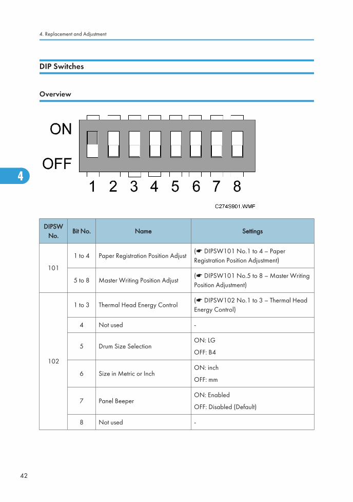
DIP Switches
Overview
DIPSWNo.
Bit No. Name Settings
101
1 to 4 Paper Registration Position Adjust(* DIPSW101 No.1 to 4 – PaperRegistration Position Adjustment)
5 to 8 Master Writing Position Adjust(* DIPSW101 No.5 to 8 – Master WritingPosition Adjustment)
102
1 to 3 Thermal Head Energy Control(* DIPSW102 No.1 to 3 – Thermal HeadEnergy Control)
4 Not used -
5 Drum Size SelectionON: LG
OFF: B4
6 Size in Metric or InchON: inch
OFF: mm
7 Panel BeeperON: Enabled
OFF: Disabled (Default)
8 Not used -
4. Replacement and Adjustment
42
4

DIPSWNo.
Bit No. Name Settings
103
1 to 4 Scanning Speed Adjustment(* DIPSW103 No.1 to 4 – Scanning SpeedAdjustment)
5 to 8 Master Feeding Speed Adjustment(* DIPSW103 No.5 to 8 – Master FeedingSpeed Adjustment)
DIPSW103 No.5 to 8 – Master Feeding Speed Adjustment
Purpose: To adjust the sub-scan magnification for the master by changing the speed of the master feedmotor.
Inputting a positive value stretches the image on the master. Inputting a negative value shrinks it.
Adjust standard: 300 ± 0.5 mm
1. Access SP6-42 (Image Adjustment Pattern Print), and then press the master making key. (* SP6-42:Image Adjustment Pattern Print)
2. Exit the SP mode, print 5 copies at 90 cpm (speed "Fast"). Use the 5th print for the adjustment.
3. The black area should be 300 ± 0.5 mm in length.
4. If it is out of the standard, then adjust DIPSW103-5 to 103-8. {(300 – Value) / 300} x 100 = ± X.X%
DIPSW103-5 DIPSW103-6 DIPSW103-7 DIPSW103-8 difference
ON ON ON ON +1.4%
OFF ON ON ON +1.2%
ON OFF ON ON +1.0%
OFF OFF ON ON +0.8%
ON ON OFF ON +0.6%
OFF ON OFF ON +0.4%
ON OFF OFF ON +0.2%
OFF OFF OFF ON 0
OFF OFF OFF OFF 0
ON ON ON OFF -1.4%
Image Adjustment
43
4

DIPSW103-5 DIPSW103-6 DIPSW103-7 DIPSW103-8 difference
OFF ON ON OFF -1.2%
ON OFF ON OFF -1.0%
OFF OFF ON OFF -0.8%
ON ON OFF OFF -0.6%
OFF ON OFF OFF -0.4%
ON OFF OFF OFF -0.2%
DIPSW101 No.1 to 4 – Paper Registration Position Adjustment
Purpose: To match the printing leading edge on the print paper with that on the original.
Adjustment standard: ±1.0 mm
The print position moves as shown below.
• The image position on a trial print, which is automatically made after making a master, tends to vary.Do not use the trial print when making adjustments.
DIPSW101-1 DIPSW101-2 DIPSW101-3 DIPSW101-4 Difference Difference
ON ON ON ON +7 pulse +3.563 mm
OFF ON ON ON +6 pulse +3.054 mm
4. Replacement and Adjustment
44
4

DIPSW101-1 DIPSW101-2 DIPSW101-3 DIPSW101-4 Difference Difference
ON OFF ON ON +5 pulse +2.545 mm
OFF OFF ON ON +4 pulse +2.036 mm
ON ON OFF ON +3 pulse +1.527 mm
OFF ON OFF ON +2 pulse +1.018 mm
ON OFF OFF ON +1 pulse +0.509 mm
OFF OFF OFF ON 0 0
OFF OFF OFF OFF 0 0
ON ON ON OFF -7 pulse -3.563 mm
OFF ON ON OFF -6 pulse -3.054 mm
ON OFF ON OFF -5 pulse -2.545 mm
OFF OFF ON OFF -4 pulse -2.036 mm
ON ON OFF OFF -3 pulse -1.527 mm
OFF ON OFF OFF -2 pulse -1.018 mm
ON OFF OFF OFF -1 pulse -0.509 mm
1 pulse = 0.509 mm
DIPSW101 No.5 to 8 – Master Writing Position Adjustment
Purpose: To match the printing side-to-side on the print paper with that on the original.
Adjustment standard: ±1.0 mm
The master writing position moves as shown below.
Image Adjustment
45
4

• The image position on a trial print, which is automatically made after making a master, tends to vary.Do not use the trial print when making adjustments.
DIPSW101-5 DIPSW101-6 DIPSW101-7 DIPSW101-8 Difference Difference
ON ON ON ON -14dot -1.185mm
OFF ON ON ON -12dot -1.016mm
ON OFF ON ON -10dot -0.847mm
OFF OFF ON ON -8dot -0.677mm
ON ON OFF ON -6dot -0.508mm
OFF ON OFF ON -4dot -0.339mm
ON OFF OFF ON -2dot -0.169mm
OFF OFF OFF ON 0 0
OFF OFF OFF OFF 0 0
ON ON ON OFF +14dot +1.185mm
OFF ON ON OFF +12dot +1.016mm
ON OFF ON OFF +10dot +0.847mm
OFF OFF ON OFF +8dot +0.677mm
4. Replacement and Adjustment
46
4

DIPSW101-5 DIPSW101-6 DIPSW101-7 DIPSW101-8 Difference Difference
ON ON OFF OFF +6dot +0.508mm
OFF ON OFF OFF +4dot +0.339mm
ON OFF OFF OFF +2dot +0.169mm
1 dot = 0.085 mm
DIPSW102 No.1 to 3 – Thermal Head Energy Control
The default is -7%. This means that during printing mode, the thermal head energy is 93 % of the maximumpower.
This can help to increase or decrease the image density. However, do not use this SP under normalcircumstances.
DIPSW102-1 DIPSW102-2 DIPSW102-3 Settings
OFF OFF OFF -7% (Standard)
OFF ON OFF -5%
OFF OFF ON -3%
OFF ON ON 0
ON OFF OFF -10%
ON ON OFF -15%
ON OFF ON -20%
DIPSW103 No.1 to 4 – Scanning Speed Adjustment
Purpose: To adjust the sub-scan magnification for scanning by changing the speed of the scanner motor.
Inputting a positive value stretches the image on the master. Inputting a negative value shrinks it.
Adjustment standard: Within 100 ± 0.5 %
1. Make a copy at 90 cpm (speed "Fast")
2. Compare the image on the print with that on the original.
3. Make sure that the difference of the sub-scan magnification is within the standard.
4. If it is out of standard, then adjust DIPSW103-1 to 103-4.
Image Adjustment
47
4

• The image position on a trial print, which is automatically made after making a master, tends to vary.Do not use the trial print when making adjustments.
DIPSW103-1 DIPSW103-2 DIPSW103-3 DIPSW103-4 Difference
ON ON ON ON +1.4%
OFF ON ON ON +1.2%
ON OFF ON ON +1.0%
OFF OFF ON ON +0.8%
ON ON OFF ON +0.6%
OFF ON OFF ON +0.4%
ON OFF OFF ON +0.2%
OFF OFF OFF ON 0
OFF OFF OFF OFF 0
ON ON ON OFF -1.4%
OFF ON ON OFF -1.2%
ON OFF ON OFF -1.0%
OFF OFF ON OFF -0.8%
ON ON OFF OFF -0.6%
ON OFF OFF OFF -0.4%
OFF ON OFF OFF -0.2%
4. Replacement and Adjustment
48
4

Covers and Boards
Front Cover, Operation Panel
[A]: Panel (x 4, x 2)
[B]: Front cover (x 6)
[C]: Front door (x 4)
Covers and Boards
49
4

Rear Cover
[A]: Rear cover (x 5)
MPU
• Remove the rear cover (* Rear Cover)
4. Replacement and Adjustment
50
4

[A]: MPU (x 8, x 8)
• Check the dip switch settings on the old MPU and make the dip switch settings [B] the same on thenew MPU.
• Adjust the master end sensor after installing the new MPU. (* Master Feed - Master End SensorAdjustment)
• Adjust the ink detection after installing the new MPU. (* Drum - Ink Detection Adjustment)
• Ensure that the EPROM on the MPU contains the correct firmware.
PSU
• Remove the rear cover (*Covers / Boards - Rear Cover)
[A]: PSU (x 6, x 3)
• When the PSU is replaced, the thermal head voltage returns to the default. Adjust the thermal headvoltage after installing the new board. (* Master Feed - Thermal Head Voltage Adjustment)
Covers and Boards
51
4

Scanner
Covers
[A]: Right side cover ( x 1)
[B]: Scanner cover ( x 4)
4. Replacement and Adjustment
52
4
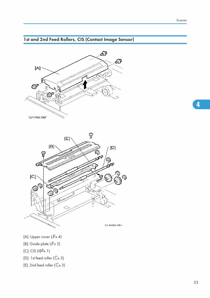
1st and 2nd Feed Rollers, CIS (Contact Image Sensor)
[A]: Upper cover (x 4)
[B]: Guide plate (x 2)
[C]: CIS (x 1)
[D]: 1st feed roller (ex 3)
[E]: 2nd feed roller (ex 3)
Scanner
53
4

Document Sensor
[A]: Upper guide plate ( x 2)
[B]: Document sensor ( x 1)
Scanner Motor
[A]: Scanner unit ( x 5, x 3)
[B]: Scanner motor ( x 2)
4. Replacement and Adjustment
54
4

Master Feed
Master Making Unit
[A]: Master making unit ( x 2, x 5)
Master Feed
55
4

Thermal Head
• Master making unit (* Master Making Unit)
[A]: Open the platen roller unit.
[B]: Thermal head upper cover ( x 2)
[C]: Thermal head side cover ( x 1)
• Close the platen roller unit.
[D]: Thermal head ( x 2)
4. Replacement and Adjustment
56
4
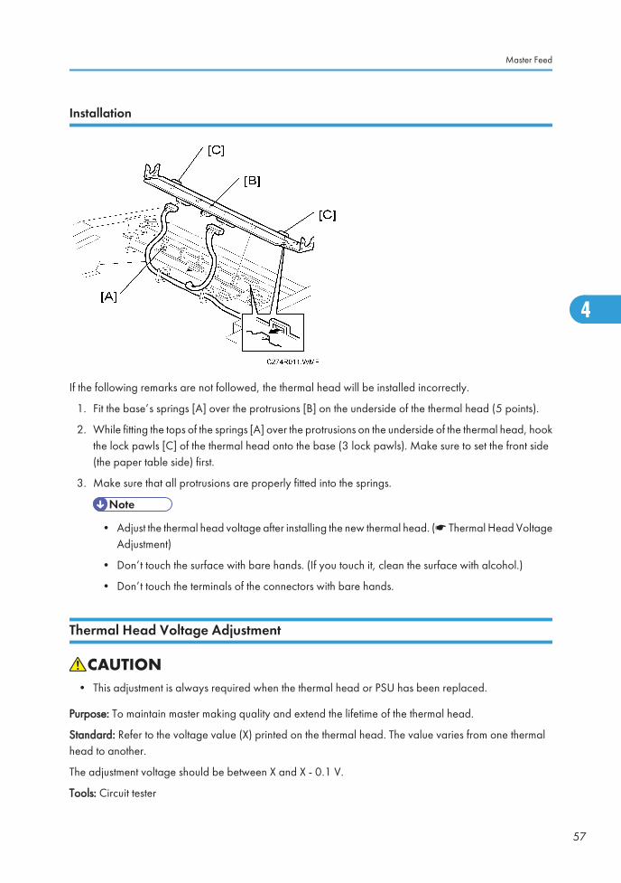
Installation
If the following remarks are not followed, the thermal head will be installed incorrectly.
1. Fit the base’s springs [A] over the protrusions [B] on the underside of the thermal head (5 points).
2. While fitting the tops of the springs [A] over the protrusions on the underside of the thermal head, hookthe lock pawls [C] of the thermal head onto the base (3 lock pawls). Make sure to set the front side(the paper table side) first.
3. Make sure that all protrusions are properly fitted into the springs.
• Adjust the thermal head voltage after installing the new thermal head. (* Thermal Head VoltageAdjustment)
• Don’t touch the surface with bare hands. (If you touch it, clean the surface with alcohol.)
• Don’t touch the terminals of the connectors with bare hands.
Thermal Head Voltage Adjustment
• This adjustment is always required when the thermal head or PSU has been replaced.
Purpose: To maintain master making quality and extend the lifetime of the thermal head.
Standard: Refer to the voltage value (X) printed on the thermal head. The value varies from one thermalhead to another.
The adjustment voltage should be between X and X - 0.1 V.
Tools: Circuit tester
Master Feed
57
4

• Remove the rear cover (* Covers / Boards - Rear Cover)
• Read the voltage value on the decal on the thermal head.
1. Connect the positive terminal of a circuit tester to TP701 and the negative terminal to TP702 on thePSU.
• If the output and ground terminals touch each other, the board will be damaged.
2. Connect the power plug, and turn on the main switch to access SP mode.
3. Select SP2-41 (Thermal head signal output).
4. Press the # key. Power is continuously supplied to the thermal head, which could damage the thermalhead, so press the clear/stop key if you cannot finish the adjustment quickly.
5. Measure the voltage, and turn VR1 on the PSU until the value is between “+0” and “-0.1” volts fromthe value on the thermal head decal.
Master End Sensor Adjustment
Purpose: To ensure that the sensor detects the end mark (a solid black area) on the master roll.
Standard: 2.0 ± 0.1 volts
Tools: The core of a used master roll (the core just before a master end display appears)
4. Replacement and Adjustment
58
4

• Remove the rear cover (* Covers / Boards - Rear Cover)
1. Place the core inside the master making unit, and close the master making cover.
2. Connect the power plug, and turn on the main switch.
3. Access SP6-41
4. Turn VR102 [A] on the MPU board until the display is 2.0 ± 0.1 volts.
Master Feed
59
4

Master Eject
Master Eject Unit
[A]: Paper delivery cover ( x 5)
[B]: Master eject box
[C]: Master eject unit ( x 2, x 3)
Master Eject Rollers
• Master eject unit (* Master Eject Unit)
4. Replacement and Adjustment
60
4

• [A]: Gears (e x 1)
[B]: Lower master eject roller (e x 2)
[C]: Upper master eject roller (e x 2, spring)
Master Eject
61
4
Paper Feed
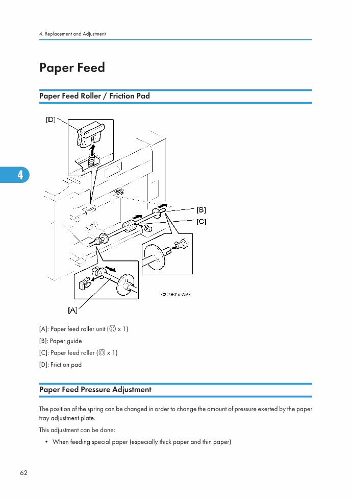
Paper Feed Roller / Friction Pad
[A]: Paper feed roller unit (c x 1)
[B]: Paper guide
[C]: Paper feed roller (c x 1)
[D]: Friction pad
Paper Feed Pressure Adjustment
The position of the spring can be changed in order to change the amount of pressure exerted by the papertray adjustment plate.
This adjustment can be done:
• When feeding special paper (especially thick paper and thin paper)
4. Replacement and Adjustment
62
4

• When the customer is experiencing feed problems.
• Front cover (* Covers / Boards – Front Cover, Operation Panel)
Increase the feed pressure: [A] [B] [C] [D]
Decrease the feed pressure: [E] [F] [G] [H]
Default position: [A] and [E] positions
Paper Separation Pressure Adjustment
The position of the screw can be changed in order to change the amount of pressure exerted by the frictionpad.
This adjustment can be done:
• When feeding special paper, especially thick paper
• When the customer is experiencing feed problems.
Paper Feed
63
4

• Remove the paper table
• Move the separation pressure slider [A] to position 1 (right end).
Increase the paper separation pressure: Move up the screws [B]
Decrease the paper separation pressure: Move down the screws [B]
Default position: lowest position
Adjustment Procedure
4. Replacement and Adjustment
64
4
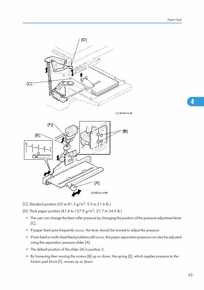
[C]: Standard position (35 to 81.5 g/m2, 9.3 to 21.6 lb.)
[D]: Thick paper position (81.6 to 127.9 g/m2, 21.7 to 34.0 lb.)
• The user can change the feed roller pressure by changing the position of the pressure adjustment lever[C].
• If paper feed jams frequently occur, the lever should be moved to adjust the pressure.
• If non-feed or multi-sheet feed problems still occur, the paper separation pressure can also be adjustedusing the separation pressure slider [A].
• The default position of the slider [A] is position 3.
• By loosening then moving the screws [B] up or down, the spring [E], which applies pressure to thefriction pad block [F], moves up or down.
Paper Feed
65
4

• The default position of the screw [B] is at the lowest position.
4. Replacement and Adjustment
66
4

Printing
Press Roller
• Take care to avoid possible injury. If the printing pressure release arms disengage, the press rollerwill be pulled upwards suddenly.
• Remove the drum
[A]: Press roller ( x 1)
The bearings on the rear and front differ. During installation, ensure that the bearing with the stopper [B]is positioned towards the rear of the machine.
Printing
67
4

Paper Registration Roller
• Remove the paper table
• Front cover (* Cover / Boards - Front Cover, Operation Panel)
• Rear cover (* Cover / Boards - Rear Cover)
• MPU (* Cover / Boards - MPU)
[A]: Registration motor (spring, x 3, belt)
[B]: Gear
[C]: Bearing ( x 2)
4. Replacement and Adjustment
68
4
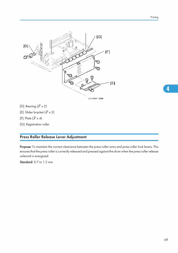
[D]: Bearing ( x 2)
[E]: Slider bracket ( x 2)
[F]: Plate ( x 4)
[G]: Registration roller
Press Roller Release Lever Adjustment
Purpose: To maintain the correct clearance between the press roller arms and press roller lock levers. Thisensures that the press roller is correctly released and pressed against the drum when the press roller releasesolenoid is energized.
Standard: 0.7 to 1.2 mm
Printing
69
4
Tools: Thickness gauge
• Front cover (* Cover / Boards - Front Cover, Operation Panel)
• Rear cover (* Cover / Boards - Rear Cover)
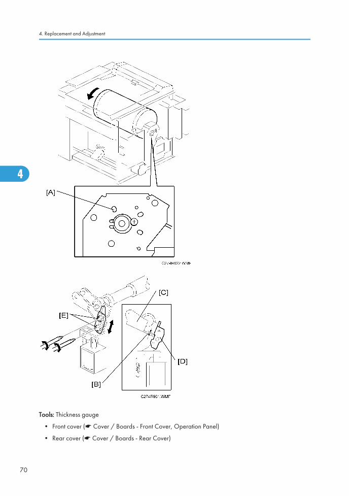
4. Replacement and Adjustment
70
4

1. Turn the drum manually until the drum master clamper on the drum moves into the lowest position.(This is when the high points of the cams on the drum flanges meet with the cam followers on bothends of the press roller.)
• To find out the correct position of the drum for the adjustment, look at the rear end of the drumshaft. The recess on the drum drive gear meets the hole [A] in the bracket when the drum is inthe correct position.
2. Using a thickness gauge, measure the clearance [B] between the press roller arm [C] and the pressroller lock lever [D] (rear side). It should be between 0.7 and 1.2 mm
3. If it is not correct, adjust the position of the press roller lock lever after loosening the two screws [E].
4. Repeat steps 2 and 3 for the front side.
Printing Pressure Adjustment
Purpose: To make better print results without decreasing the run length.
Standard: Within 10 ± 0.5 mm
• Paper delivery unit (* Paper Delivery – Paper Delivery Unit)
1. Adjust the distance [A] to 10 ± 0.5 mm by turning the adjusting bolt [B].
2. Repeat the same procedure for the printing pressure spring at the non-operation side.
Printing
71
4

Drum
Preparation
Before attempting any of the procedures in this section, wipe off the ink around the ink roller. To do this,set SP3-6 (ink detection) to off, and feed paper until ink ends. The setting value returns to the default valuewhen power is switched off/on.
Cloth Screen
• Remove the drum
1. Remove the drum upper bracket ( x 4).
2. Release the stopper [A], then rotate the drum until the master clamper faces top.
3. Remove the cloth screen [B] (x 4).
4. Replacement and Adjustment
72
4

Installation
Drum
73
4

• Do not scratch the cloth screen or metal screen.
• Properly insert the edge of the belt crossing [A] on the cloth screen under the mylar [B] on the metalscreen, as shown above.
Otherwise, ink will leak from the trailing edge of the master on the drum during a long printing run.
• Make sure that the correct side of the screen is facing up. In addition, make sure that the stays forsecuring the cloth screen are positioned correctly. (Refer to the upper illustration.)
• When replacing the cloth screen, spread the screen around the metal screen while strongly pullingthe stay [C]. Adjust the stay so that it is parallel to the master clamper, then tighten the screws.
• Make sure that the cloth screen is not wrinkled while spreading it around the drum.
4. Replacement and Adjustment
74
4
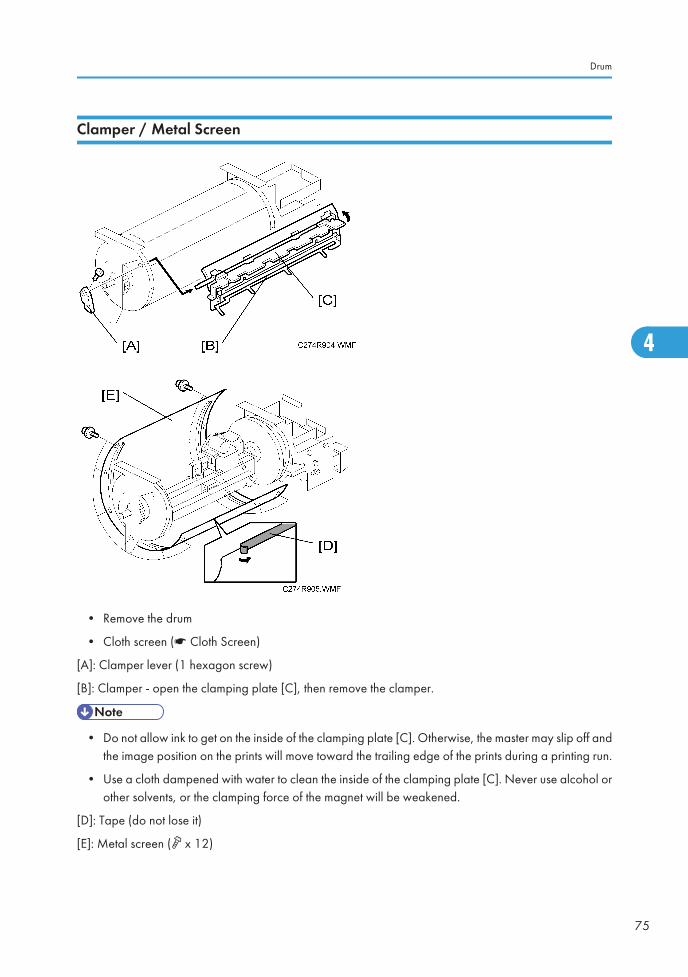
Clamper / Metal Screen
• Remove the drum
• Cloth screen (* Cloth Screen)
[A]: Clamper lever (1 hexagon screw)
[B]: Clamper - open the clamping plate [C], then remove the clamper.
• Do not allow ink to get on the inside of the clamping plate [C]. Otherwise, the master may slip off andthe image position on the prints will move toward the trailing edge of the prints during a printing run.
• Use a cloth dampened with water to clean the inside of the clamping plate [C]. Never use alcohol orother solvents, or the clamping force of the magnet will be weakened.
[D]: Tape (do not lose it)
[E]: Metal screen ( x 12)
Drum
75
4

Installation
• Make sure that the correct end of the metal screen is overlapping. (The right side overlaps, as viewedfrom the non-operation side, as shown above.)
• Secure the metal screen with filament tape.
• The 4 screws holding the drum master clamper are longer than the 12 screws holding the metal screen,although they are similar in appearance. Be careful not to mix them up or use the wrong screws.
• When installing the metal screen, secure the trailing edge first with the 2 screws. Then, tighten theother screws while removing the slack from the screen. Make sure that the gap between the drum
4. Replacement and Adjustment
76
4

flanges and the screen is 0.3 mm or less, as shown above. (The two holes [A] on the trailing side areround holes and the other holes are long holes, to allow for the removal of the slack.)
• Position the springs [B] and [C] (one each at the front and rear) as shown when reinstalling the drummaster clamper [D].
• Do not scratch the cloth screen or metal screen.
Ink Pump Unit
• Remove the drum
• Cloth screen (* Cloth Screen)
• Clamper / Metal screen (* Clamper / Metal Screen)
[A]: Ink pump unit ( x 1, x 2)
Drum
77
4

Ink Roller Unit / Ink Roller One Way Clutch
• Wipe off the ink around the ink roller beforehand (use SP3-6).
• Remove the drum
• Cloth screen (* Cloth Screen)
• Clamper / Metal screen (* Clamper / Metal Screen)
[A]: Connector cover ( x 2, x 2)
[B]: Ink socket ( x 1)
[C]: Front drum bracket ( x 3)
[D]: Front drum flange
4. Replacement and Adjustment
78
4
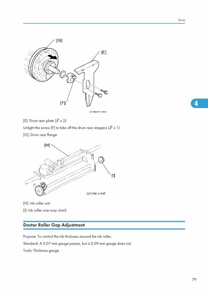
[E]: Drum rear plate ( x 2)
Untight the screw [F] to take off the drum rear stoppers ( x 1)
[G]: Drum rear flange
[H]: Ink roller unit
[I]: Ink roller one-way clutch
Doctor Roller Gap Adjustment
Purpose: To control the ink thickness around the ink roller.
Standard: A 0.07-mm gauge passes, but a 0.09-mm gauge does not.
Tools: Thickness gauge
Drum
79
4

• Normally the doctor roller gap is not adjusted or changed. It tends to be difficult to change in the field.If the gap is too narrow, an uneven image may appear on the prints. If it is too wide, too much inkwill be applied to the drum screens, resulting in ink leakage from the drum.
• Wipe off the ink around the ink roller beforehand. (Use SP3-6.)
• Remove the drum
• Remove the Ink roller unit
1. Make sure that a 0.07 mm gap gauge goes through the gap [A] between the ink and doctor rollers,and that a 0.09 mm gap gauge does not.
• The gap should be checked at both ends of the doctor roller. Insert a gap gauge at each end ofthe roller. The gap tends to be larger for the center.
• While the gap gauge is inserted, hold the doctor and ink rollers with your fingers in order to stopthe rollers from rotating.
• While the gap gauge is inserted, hold the end of the gap gauge.
2. If the gap is out of the standard, loosen the screw [B] and adjust the gap by turning the cam bushing[C] for the front and for the rear.
• Make sure to repeat the adjustment for both ends of the rollers.
4. Replacement and Adjustment
80
4
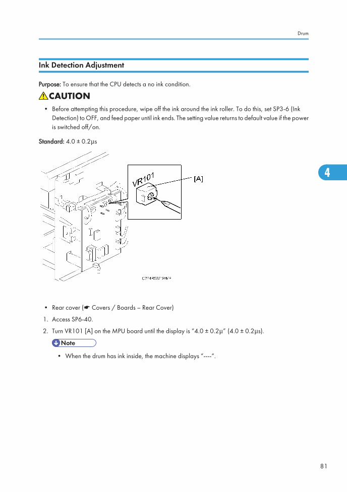
Ink Detection Adjustment
Purpose: To ensure that the CPU detects a no ink condition.
• Before attempting this procedure, wipe off the ink around the ink roller. To do this, set SP3-6 (InkDetection) to OFF, and feed paper until ink ends. The setting value returns to default value if the poweris switched off/on.
Standard: 4.0 ± 0.2μs
• Rear cover (* Covers / Boards – Rear Cover)
1. Access SP6-40.
2. Turn VR101 [A] on the MPU board until the display is “4.0 ± 0.2μ” (4.0 ± 0.2μs).
• When the drum has ink inside, the machine displays “----“.
Drum
81
4

Paper Delivery
Paper Delivery Unit
• Rear cover (* Covers / Boards - Rear Cover)
[A]: Paper delivery cover ( x 5)
4. Replacement and Adjustment
82
4

[B]: Paper delivery unit ( x 2, x 2, c x 1)
Delivery Belt / Paper Exit Sensor
• Paper delivery unit (* Paper Delivery Unit)
[A]: Vacuum fan motor bracket ( x 4)
[B]: Delivery belts
[C]: Paper exit sensor ( x 1)
Paper Delivery
83
4
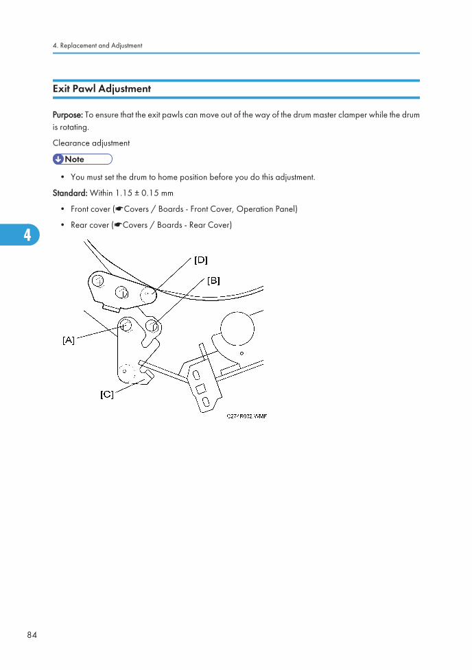
Exit Pawl Adjustment
Purpose: To ensure that the exit pawls can move out of the way of the drum master clamper while the drumis rotating.
Clearance adjustment
• You must set the drum to home position before you do this adjustment.
Standard: Within 1.15 ± 0.15 mm
• Front cover (*Covers / Boards - Front Cover, Operation Panel)
• Rear cover (*Covers / Boards - Rear Cover)
4. Replacement and Adjustment
84
4

1. Loosen screw [A] then screw [B] in this order (do not remove them). Make sure that the bracket [C]becomes free from engagement and the cam follower [D] contacts the drum flange.
2. Using a gap gauge, measure the clearance [E] between the drum surface and the exit pawls. It shouldbe 1.15 ± 0.15 mm.
3. If the clearance is not correct, adjust the clearance by turning the bolt [F].
4. Reposition the bracket [C] and tighten the screws [A] and [B].
5. Do the timing adjustment (see the next section).
Timing Adjustment
Standard: 0 or less than 0.5 mm
Paper Delivery
85
4

• Front cover (* Covers / Boards - Front Cover, Operation Panel)
• Rear cover (* Covers / Boards - Rear Cover)
4. Replacement and Adjustment
86
4

Do this after the clearance adjustment (the procedure is on the next page).
1. Turn the drum manually until the recess in the drum drive gear meets the positioning hole [A] in thebracket, as shown.
2. Loosen screw [B] then screw [C] in that order (do not remove them). Make sure that the bracket [D]becomes free from engagement and the cam follower [E] contacts the drum flange.
3. Measure the gap [F] between the cam follower and cam face (front drum flange). It should be 0 to0.5 mm.
4. If the gap is not correct, loosen the two screws securing the cam follower bracket [G].
5. Re-tighten the two screws while pushing the cam follower against the cam face. Make sure that thegap [F] is 0 or less than 0.5 mm.
• Do not push the cam followers too strongly against the cam.
6. Re-position the bracket [D] and tighten the screws [B] and [C].
Paper Delivery
87
4

Main Drive
Main Drive Timing Belt Adjustment
After the timing belt is replaced, correct belt tension must be applied.
• Rear cover (* Covers / Boards - Rear Cover)
• MPU (* Covers / Boards - MPU)
• PSU (* Covers / Boards - PSU)
1. Loosen the screws [A], [B], and [C].
2. Move the tension roller [D] to the right with a screwdriver [E] as shown.
3. Tighten the screws [A], [B], and [C].
4. Remove the screwdriver.
Main Motor Pulley Position
After putting the pulley back on the main motor shaft, refer to the above illustration for the correct positionof the pulley.
4. Replacement and Adjustment
88
4

Main Drive
89
4

Firmware UpdateThe firmware in the EPROM on the MPU can be upgraded replacing the EPROM.
1. Before upgrading the firmware, check the current suffix version with SP3-1.
2. Turn off the main switch and disconnect the power plug.
3. Remove the rear cover.
4. Replace the EPROM on the MPU.
5. Connect the power plug and turn on the main switch.
6. Access SP3-1 and confirm that the suffix version was changed.
4. Replacement and Adjustment
90
4

5. System Maintenance Reference
Service Program Mode
• Make sure that the data-in LED (N) is not on before you go into the SP mode. This LED indicates thatsome data is coming to the machine. When the LED is on, wait for the copier to process the data.
SP Tables
See "Appendices" for the following information:
• SP Tables
Using Service Program Modes
Use the service program modes (SP modes) to check electrical data, change operating modes, and adjustvalues.
• The Service Program Mode is for use by service representatives only so that they can properly maintainproduct quality. If this mode is used by anyone other than service representatives for any reason, datamight be deleted or settings might be changed. In such case, product quality cannot be guaranteedany more.
Entering SP Mode
1. Press the following sequence of keys.
→ → → →
Or
→ → Combine Key →
2. Hold the key down for longer than 3 seconds.
3. The SP number is displayed. (e.g. SP1)
Leaving SP Mode
To exit SP mode, press Clear Modes/Recovery
91
5

Using the SP Mode
SP command numbers can be entered directly.
1. Using the number keys, enter the desired main-menu number, then press the Enter key.
2. Using the number keys, enter the desired sub-menu number, then press the Enter key.
3. Enter the desired value using the number keys.
4. Press the enter key to store the displayed setting.
5. System Maintenance Reference
92
5

6. Troubleshooting
Service Call ConditionsSee "Appendices" for the following information:
• SC tables
93
6

Electrical Component DefectsSee "Appendices" for the following information:
• Electrical component defects
6. Troubleshooting
94
6

Fuse, LED, VR, DIP-SW, AND TP TablesSee "Appendices" for the following information:
• Fuse table
• LED table
• VR table
• DIP switch table
• Test point (TP) table
Fuse, LED, VR, DIP-SW, AND TP Tables
95
6

MEMO
96 EN

Model Titanium3
Machine Code: C274
Appendices
March 2009
Subject to change


TABLE OF CONTENTS1. Appendix: Specifications
General Specifications.......................................................................................................................................3
Main Frame....................................................................................................................................................3
2. Appendix: Maintenance Tables
Maintenance Table............................................................................................................................................7
3. Appendix: Service Call Condition
SC Tables............................................................................................................................................................9
4. Appendix: Electrical Component Defects
Electrical Component Defects.........................................................................................................................11
Fuse, LED, VR, DIP-SW, and TP Tables..........................................................................................................13
Blown Fuse Conditions................................................................................................................................13
LED’S.............................................................................................................................................................14
VR’S..............................................................................................................................................................14
DIP Switches.................................................................................................................................................14
Test Points.....................................................................................................................................................15
5. Appendix: SP Mode Tables
Input Mode.......................................................................................................................................................17
SP Table........................................................................................................................................................17
Output Mode....................................................................................................................................................20
SP Table........................................................................................................................................................21
Test Mode.........................................................................................................................................................23
SP Table........................................................................................................................................................23
Adjustment Mode.............................................................................................................................................24
SP Table........................................................................................................................................................24
1

2

1. Appendix: Specifications
General Specifications
Main Frame
Configuration Desktop
Master Process Digital with 300 dpi thermal head
Scanning (Pixel Density) 300 dpi
Originals Sheet
Printing Process Fully automatic one-drum stencil system
Original Size Maximum: 275 x 395 mm / 10.8" x 15.6"
Minimum: 90 x 140 mm / 3.5" x 5.5"
Original Weight 40.7 – 127.9 g/m2
Copy Paper Size Maximum: 275 x 395 mm / 10.8" x 15.6"
Minimum: 90 x 140 mm / 3.5" x 5.5"
Copy Paper Weight 35.0 – 127.9 g/m2 (10 to 30 °C)
Printing Speed 60, 90cpm (2 steps)
Reproduction Rations Metric (%): 141, 122, 115, 93, 87, 82, 71
Inch (%): 155, 129, 121, 93, 77, 74, 65
Master Eject Box Capacity 30 masters
Paper Capacity 500 sheets (75 g/m2, 20 lb)
Paper Delivery Tray Capacity 500 sheets (80 g/m2, 20 lb)
Power Source North America: 120 V, 60 Hz, 2.0 A
Europe/Asia: 220 - 240 V, 50/60 Hz, 1.1 A
Power Consumption 110 - 120V: Less than 175W, Less than 2.9A
220 - 240V: Less than 175W, less than 1.3A
3
1

Noise Emission Operating Position Sound Power Level:
Standby: Not above 22.5 db
Copying 60 rpm: Not above 64 db
Copying 90 rpm: Not above 68 db
Sound Power Level:
Standby: Not above 31.2 db
Copying 60 rpm: Not above 77 db
Copying 90 rpm: Not above 80 db
Dimensions (W x D x H) Set up: 1332 x 672 x 519 mm (52.5" x 26.4" x 20.5")
Stored: 582 x 672 x 519 mm (23.0" x 26.4" x 20.5")
Weight 54 kg (119lb.)
Master Processing Time Less than 40 seconds (A4M, 8½" x 14M)
First Print Time Less than 42 seconds (A4M, 8½" x 14M)
Leading Edge Margin 5 mm ±3 mm
Side Registration Adjustable Range + 14mm to - 9mm
Vertical Registration Adjustable Range ±10 mm
Master Master type 280 mm width (B4), 50 m/roll
240 mm width (LG), 50 m/roll
Yield 100 masters/roll
Maximum run length per master 2000 prints/master
Storage conditions 0 to 40 °C, 10 to 95 %RH
Storage period One year after production date
1. Appendix: Specifications
4
1
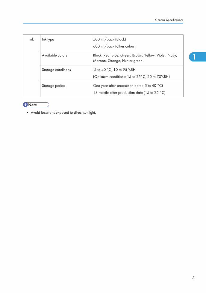
Ink Ink type 500 ml/pack (Black)
600 ml/pack (other colors)
Available colors Black, Red, Blue, Green, Brown, Yellow, Violet, Navy,Maroon, Orange, Hunter green
Storage conditions -5 to 40 °C, 10 to 95 %RH
(Optimum conditions: 15 to 25°C, 20 to 70%RH)
Storage period One year after production date (-5 to 40 °C)
18 months after production date (15 to 25 °C)
• Avoid locations exposed to direct sunlight.
General Specifications
5
1

1. Appendix: Specifications
6
1

2. Appendix: Maintenance Tables
Maintenance TableThe following items should be maintained periodically. There are two sets of intervals - one based on timeand the other based on print count. For maintenance items with entries in both of them, use whichever comesfirst.
Symbol key: C: Clean, R: Replace, L: Lubricate, A: Adjust
• Turn off the main power switch and unplug the machine before performing any procedure in thissection.
Internal
Item
Time Print Counter
EM Note6M 1Y 2Y 5Y 150K 300K 600K
1.2M
3M
Scanner/Optics
CIS C C C C C Dry Cloth
1st Feed Roller C C C C C CDampCloth
2nd FeedRoller
C C C C C CDampCloth
Shading Plate(White Plate)
C C C C
Dry Cloth,
Expectedlife is 10kmasters.
Master Feed
Thermal Head C C C C C Alcohol
Platen Roller C C Alcohol
Master EndSensor
C C Dry Cloth
Paper Feed
7
2

Paper FeedRoller
C R R R C R R R CDampCloth
Friction Pad R R R R R R R RWater orAlcohol
Press Roller C C R C R C Alcohol
Exit Sensor C Dry Cloth
RegistrationSensor
C C C C C Dry Cloth
RegistrationRollers
CWater orAlcohol
Paper DeliveryUnit Bushings
C
L
C
L
Motor Oil(SAE #20)
Paper FeedClutch
R
Feed StartTiming Sensor
C Dry Cloth
Drum and Ink Supply
Cloth Screen R R
Ink Nozzle C C C C CDampCloth
Drum ClamperPlate/Magnet
C C C CWater orAlcohol
Drum MasterSensor
CDry Cloth
Black Patch C C C C Dry Cloth
Drum DriveGear and Cam
L L L
Grease
(Alvania#2)
2. Appendix: Maintenance Tables
8
2

3. Appendix: Service Call Condition
SC TablesNo. Symptom Possible cause
E-00
Clamper error
The MPU cannot detect the clamper position sensor signal (openor closed) within 3.0 seconds after the clamper motor turns on.
Clamper drive
Clamper sensors
Clamper motor
E-01
Cutter error
The cutter HP sensor does not turn on within 3.0 seconds afterthe cutter motor turns on.
Cutter drive
Cutter switch
Cutter motor
E-03Thermal Head ID Error
The CPU detects on abnormal ID signal from the thermal head.
Thermal head
MPU
E-04
Thermal Head Overheat
The temperature of the thermal head is greater than 54°C whenthe Start key is pressed.
Overheat (wait for thethermal head to cool down)
Thermal head
E-06
Main Motor error
The CPU cannot detect the master eject position sensor (drumHP) signal within 2.5 seconds after the main motor turns on.
Main motor drive
Main motor
Motor drive board
Master eject position SN
E-09Thermal Head Thermistor Open
The thermistor output voltage is over 4.9 volts.
Thermal head thermistor
Thermal head connector
E-10
Thermal Heard Drive Failure
The CPU detects an abnormal condition in the thermal head drivecircuit.
Thermal head
MPU
Thermal head connector
E-12
Pressure Plate error
The pressure plate home position sensor signal is not detectedwithin 3.0 seconds after the pressure plate motor turns on.
Pressure plate drive
Pressure plate motor
Plate position sensors
E-14IPU error
Signal transmission error (from the IPU) occurred in the MPU
MPU
9
3

No. Symptom Possible cause
E-23
Master Eject Position Sensor (Drum HP) error
The master eject position sensor does not activate before the feedstart timing sensor activates.
Master eject position sensor
Feed start timing sensor
Feeler
E-24
Feed Start Timing Sensor error
The feed start timing sensor does not activate before the mastereject sensor activates.
Master eject position sensor
Feed start timing sensor
Feeler
3. Appendix: Service Call Condition
10
3

4. Appendix: Electrical ComponentDefects
Electrical Component Defects
Component Condition Symptom
Original SensorOpen The P jam indicator is lit whenever the main switch is on.
Shorted The P jam indicator is lit whenever a master is made.
Master Eject SensorOpen The E jam indicator is lit whenever the main switch is on.
Shorted The E jam indicator is lit whenever a used master is ejected.
Pressure Plate HPSensor
Open E-12 is displayed whenever the main switch is on.
Shorted
Pressure Plate LimitSensor
Open E-12 is displayed whenever the main switch is on.
Shorted The master eject indicator is lit whenever the main switch is on.
Feed Start TimingSensor
Open E-6 is displayed whenever the main switch is on.
Shorted E-24 is displayed whenever the main switch is on.
11
4

Component Condition Symptom
Master Eject Position(Drum HP) Sensor
Open E-6 is displayed whenever the main switch is on.
Shorted E-23 is displayed whenever the main switch is on.
Drum Master Sensor
Open The D jam indicator is lit whenever a proof print is made.
ShortedThe D jam indicator is lit whenever a master is made.
The M indicator is lit whenever a copy is made.
Paper Exit SensorOpen The C jam indicator is lit whenever the main switch is on.
Shorted The B jam indicator is lit whenever a copy is made.
4. Appendix: Electrical Component Defects
12
4

Fuse, LED, VR, DIP-SW, and TP Tables
Blown Fuse Conditions
MPU
No. Rate Possible cause
FU101 1 A Ink pump motor
PSU
No. Rate Possible cause
FU700 6.3 A AC Line
FU701 6.3 AMain motor
Main motor control board
FU702 6.3 A
Paper feed clutch
Air knife fan motor
Front/Rear pressure release solenoid
Vacuum fan motor
Ink pump motor
Master eject motor
Master/Paper counter
Contact Image Sensor (CIS)
Pressure plate motor
Scanner motor
Clamper motor
Master feed motor
Fuse, LED, VR, DIP-SW, and TP Tables
13
4

LED’S
MPU
No. Function
LED103OFF: Low ink condition
ON: Sufficient ink condition
VR’S
MPU
No. Function
VR101 Adjust the ink detection. (* Replacement and Adjustment – Drum - Ink Detection Adjustment)
VR102 Adjust the master end sensor. (* Replacement and Adjustment – Master Feed - Master EndSensor Adjustment)
PSU
No. Function
VR1Adjust the thermal head voltage. (* Replacement and Adjustment - Master Feed - ThermalHead Voltage Adjustment)
DIP Switches
MPU
DIPSWNo.
Bit No. Name Settings
101
1 to 4Paper Registration PositionAdjust
(* Replacement and Adjustment – ImageAdjustment - DIPSW101 No.1 to 4 – PaperRegistration Position Adjustment)
5 to 8Master Writing Position Adjust (* Replacement and Adjustment – Image
Adjustment - DIPSW101 No.5 to 8 – MasterWriting Position Adjustment)
4. Appendix: Electrical Component Defects
14
4

DIPSWNo.
Bit No. Name Settings
102
1 to 3Thermal Head Energy Control (* Replacement and Adjustment – Image
Adjustment - DIPSW102 No.1 to 3 – ThermalHead Energy Control)
4 Not used -
5Drum Size Selection ON: LG
OFF: B4
6Size in Metric or Inch ON: inch
OFF: mm
7Panel Beeper ON: Enabled
OFF: Disabled
8 Not used -
103
1 to 4Scanning Speed Adjustment (* Replacement and Adjustment – Image
Adjustment - DIPSW103 No.1 to 4 –Scanning Speed Adjustment)
5 to 8Master Feeding SpeedAdjustment
(* Replacement and Adjustment – ImageAdjustment - DIPSW103 No.5 to 8 – MasterFeeding Speed Adjustment)
Test Points
MPU
No. Function
TP101 GND
TP103 Measures the ink detection pulse
TP104 Measures the ink detection pulse (standard pulse)
TP113 GND
Fuse, LED, VR, DIP-SW, and TP Tables
15
4

PSU
No. Function
TP701 Thermal head voltage
TP702 GND
4. Appendix: Electrical Component Defects
16
4

5. Appendix: SP Mode Tables
Input Mode
SP Table
No. Name Note
1-3 Original Sensor
1-26 Master End Sensor
1-27 Ink Detection Signal
1-31 Pressure Plate Home Position Sensor
1-32 Pressure Plate Limit Position Sensor
1-33 Master Eject Box Set Sensor
1-42 Paper Exit Sensor
1-43 Master Eject Sensor
1-44 Drum Master Sensor
1-52 Door Safety Switch
Master Making Unit Set Sensor
1-53 Cutter Home Position Sensor
1-56 Feed Start Timing Sensor
1-59 Master Eject Position Sensor
1-62 Drum Set Signal
1-65 Clamper Close Sensor
1-66 Clamper Open Sensor
1-68 Paper Registration Sensor
1-70 Master Set Cover Sensor
17
5

No. Name Note
1-71 DIPSW 103-1 Use these SPs to test whether the DIP switchesare working properly.
1-72 DIPSW 103-2
1-73 DIPSW 103-3
1-74 DIPSW 103-4
1-75 DIPSW 103-5
1-76 DIPSW 103-6
1-77 DIPSW 103-7
1-78 DIPSW 103-8
1-79 DIPSW 101-1
1-80 DIPSW 101-2
1-81 DIPSW 101-3
1-82 DIPSW 101-4
1-83 DIPSW 101-5
1-84 DIPSW 101-6
1-85 DIPSW 101-7
1-86 DIPSW 101-8
1-87 DIPSW 102-1
1-88 DIPSW 102-2
1-89 DIPSW 102-3
1-90 DIPSW 102-4
5. Appendix: SP Mode Tables
18
5

No. Name Note
1-91 DIPSW 102-5
1-92 DIPSW 102-6
1-93 DIPSW 102-7
1-94 DIPSW 102-8
Input Mode
19
5

Output Mode
5. Appendix: SP Mode Tables
20
5

SP Table
No. Name Note
2-3 Master Eject Motor Press and hold the master making key to startthe test. Release the key to stop the test.
2-6 Vacuum Fan Motor
2-7 Air Knife Fan Motor
2-9 Master Counter
2-10 Paper Counter
2-12 Ink Pump Motor
2-14 Pressure Release Solenoids
2-21 Exposure Lamp (Xenon Lamp)
2-22 Cutter Motor: + direction
2-23 Cutter Motor: to Home
2-24 Cutter Motor: - direction
2-27 Main Motor: to drum home position
2-28 Main Motor: to master making position
2-36 Master Feed Motor
2-37 Scanner Motor
2-41 Thermal Head Signal Output (VHD Signal)(* Explanation Below)
2-42 Paper Feed Clutch
2-44 Clamper Motor: to close
2-45 Clamper Motor: to open
2-46 Pressure Plate Motor: to limit
2-47 Pressure Plate Motor: to home position
2-48 Main Motor: 30rpm
2-49 Main Motor: 60rpm
2-50 Main Motor: 90rpm
2-51 Paper Feed Motor: 30rpm
Output Mode
21
5

No. Name Note
2-52 Paper Feed Motor: 60rpm Press and hold the master making key to startthe test. Release the key to stop the test.
2-53 Paper Feed Motor: 90rpm
SP2-41: Thermal Head Signal Output (VHD Signal)
Applies thermal head voltage.
Power is applied by pressing the # key. To protect the thermal head, the voltage supply is automaticallystopped after 30 seconds. It is also stopped by pressing the clear/stop key.
(* Replacement and Adjustment – Master Feed - Thermal Head Voltage Adjustment)
5. Appendix: SP Mode Tables
22
5

Test Mode
SP Table
No. Name Function
3-1 Firmware Suffix Information (* Explanation Below)
3-4 All Indicators ON Turns on all the indicators on the operation panel by pressing themaster making key.
3-5 Test Pattern Print Print the thermal head test pattern by pressing the master makingkey.
3-6 Ink Detection Specifies whether ink detection is done.
0: OFF
1: ON (Default)
The setting value returns to default value in power switch off.
SP3-1: Firmware Suffix Information
This model has no LCD, so the suffix is displayed as shown below instead of in Latin letters.
• The letters “i”, “o” and “u” are always skipped.
Test Mode
23
5

Adjustment Mode
SP Table
No. Name Function
6-40 Ink Detection Adjustment (* Replacement and Adjustment – Drum - Ink DetectionAdjustment)
6-41 Master End Sensor Adjustment (* Replacement and Adjustment – Master Feed - MasterEnd Sensor Adjustment)
6-42 Image Adjustment Pattern Print (* Explanation below)
SP6-42: Image Adjustment Pattern Print
This test pattern is used for master feeding speed adjustment.
• Master Feeding Speed Adjustment: (* Replacement and Adjustment – Image Adjustment -DIPSW103 No.5 to 8 – Master Feeding Speed Adjustment)
This test pattern is generated in the MPU, and does not use the scanner unit. So, this pattern can also beused to determine whether an image problem is caused by the scanner or the thermal head.
If there is an image problem during copying but the test print is OK, the problem could be in the scannerunit.
The print paper should be B4 or LG size when using this test pattern.
5. Appendix: SP Mode Tables
24 EN
5


