8
WORK TABLE ASSEMBLY INSTRUCTIONS Riff Tables
| Date post: | 09-Sep-2018 |
| Category: |
Documents |
| Upload: | phungtuyen |
| View: | 216 times |
| Download: | 0 times |

WORK TABLEASSEMBLY INSTRUCTIONS
Riff Tables
Riff Tables by OFS | Assembly Instructions Page 2 of 7
Work Table Assembly Instructions
1
2
3
4
5
6
7
8
9
10
10
11
12 13
RIFF WORK TABLE ASSEMBLY
9
ITEM NO. PART NAME DESCRIPTION QTY.1 TOP TOP 22 LEG ASSY LEG ASSY 23 CTR LEG ASSY CTR LEG ASSY 1
4 SUPPORT ASSY CROSS RAIL (UNDER) 2
5 CROSS RAIL-UNDER
CROSS RIAL-UNDER 2
6 CROSS RAIL-OVER
CROSS RAIL-OVER 2
7 BRACE BRACE 48 1000599 LEVELER 6
9 8 X 2.5 PANHEAD (HK-101) SCREW 16
10 8 X 2 PANHEAD (HK-102) SCREW 12
11 8 X 1.5 PANHEAD (HK-103) SCREW 8
12 8 X 1.25 PANHEAD (HK-104) SCREW 16
13 8 X .625 PANHEAD (HK-105) SCREW 56
1
2
3
8
5
7
10
6
11
4
9
12 13
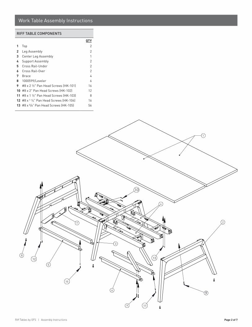
RIFF TABLE COMPONENTS
1 TopQTY
22 Leg Assembly 23 Center Leg Assembly 14 Support Assembly 25 Cross Rail-Under 26 Cross Rail-Over 27 Brace 48 1000599/Leveler 69 #8 x 2 ½" Pan Head Screws (HK-101) 1610 #8 x 2" Pan Head Screws (HK-102) 1211 #8 x 1 ½" Pan Head Screws (HK-103) 812 #8 x 1 ¼” Pan Head Screws (HK-104) 1613 #8 x 5/8” Pan Head Screws (HK-105) 56

Page 3 of 7 Riff Tables by OFS | Assembly Instructions
Work Table Assembly Instructions
STEP 1
1. Place Worksurfaces, bottom side up, on a non-marring surface.
2. Align Notches and slide Under Top Assemblies onto Center Base (96" long tops only).
3. Connect End Bases to Under Top Assemblies by inserting Tennons into Mortises.
4. Secure Bases to Under Top Assembly with #8 x 5/8" Pan Head Screws (HK-105).
Mortise
Tennon
Notches
End baseCenter base (96" tops)
Under topassemblies
IMPORTANT!Mortises must be
toward table center
96" long tops only
Place work surfaces, bottom side up, on a non-marring surface.•
Align notches and slide Under top assemblies onto Center base (96" long tops only).•
Connect End bases to Under top assemblies by inserting tennons into mortises.•
Secure bases to Under top assembly with #8 x 5/8"•pan head screws (HK-105).
Series: Part #:Verve X1
Center Base (96" tops)
96" long tops only
Under TopAssemblies
IMPORTANT!Mortises must be
toward table center
NotchesMortise
Tennon
End Base

Riff Tables by OFS | Assembly Instructions Page 4 of 7
Work Table Assembly Instructions
STEP 2
1. Fit Cross Rail Angled Tennons into Mortise on bottom of Base Rail.
2. Straight Tennons fit on top and bottom of Center Base Rail (96" long tops only).
3. Secure Angled Tennons with #8 x 1 ½" Pan Head Screws (HK-103).
4. Secure Straight Tennons with (2) #8 x 2" Pan Head Screws (HK-102).
Straighttennon
Align holes withholes in base rail Angled tennon
Mortise
96" long tops only
Fit Cross rail angled tennons into motise on bottom of base rail.•
Straight tennons fit on top and bottom of center base rail (96" long tops only).•
Secure angled tennons with # 8 x 1 1/2" pan head screws (HK-103).•
Secure straight tennons with (2) #8 x 2" pan head screws (HK-102). •
Series: Part #:Verve X1
Align holes withholes in Base Rail
96" long tops only
Angled Tennon
Mortise
StraightTennon
Page 5 of 7 Riff Tables by OFS | Assembly Instructions
Work Table Assembly Instructions
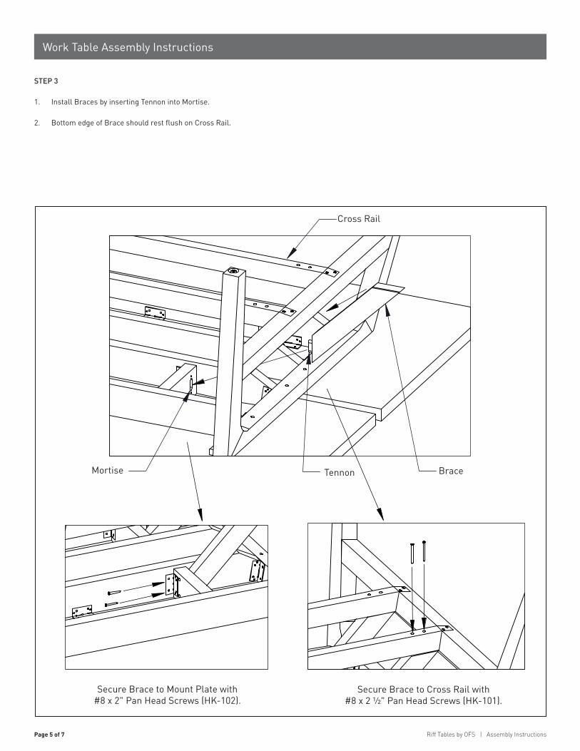
STEP 3
1. Install Braces by inserting Tennon into Mortise.
2. Bottom edge of Brace should rest flush on Cross Rail.
Mortise Tennon
Cross rail
Brace
Insall Braces by inserting tennon into mortise•
Bottom edge of Brace should rest flush on Cross rail.•
Secure Brace to Mount plate with#8 x 2" pan head screws (HK-102).
Secure Brace to Cross rail with#8 x 2 1/2" pan head screws (HK-101)
Series: Part #:Verve X1
Cross Rail
Secure Brace to Cross Rail with #8 x 2 ½" Pan Head Screws (HK-101).
Secure Brace to Mount Plate with #8 x 2" Pan Head Screws (HK-102).
BraceMortise Tennon
Riff Tables by OFS | Assembly Instructions Page 6 of 7
Work Table Assembly Instructions
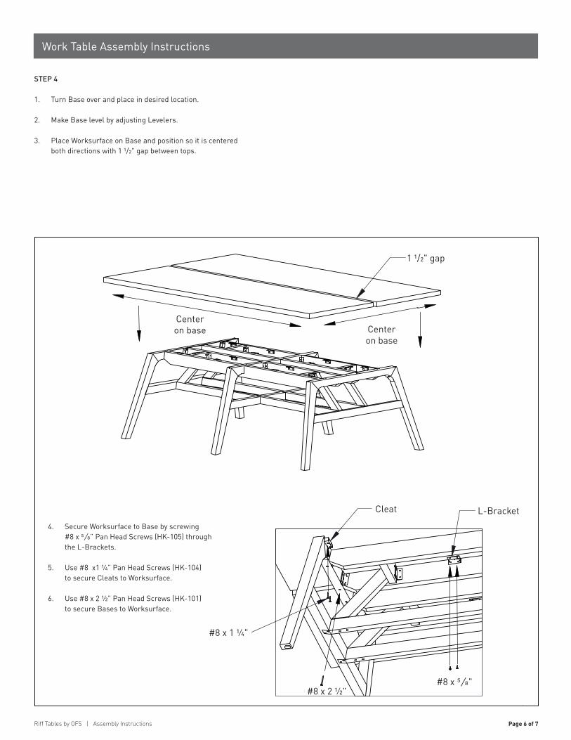
STEP 4
1. Turn Base over and place in desired location.
2. Make Base level by adjusting Levelers.
3. Place Worksurface on Base and position so it is centered both directions with 1 1/2" gap between tops.
Centeron
baseCenter
onbase
1 1/2" gap
#8 x 1 1/4"
#8 x 2 1/2"#8 x 5/8"
L-BracketCleat
Turn base over and place in desired location.•
Make base level by adjusting levelers.•
Place work surface on base and position so it is centered both directions with 1 1/2"•gap between tops.
Secure Work surface to base by•screwing #8 x 5/8" pan head screws(HK-105) through the L-Brackets.
Use #8 x 1 1/4" pan head screws•(HK-104) to secure cleats to work surface.
Use #8 x 2 1/2" pan head screws (HK-101)•to secure bases to work surface.
Series: Part #:Verve X1
Center on base Center
on base
L-BracketCleat
4. Secure Worksurface to Base by screwing #8 x 5/8” Pan Head Screws (HK-105) through the L-Brackets.
5. Use #8 x1 ¼” Pan Head Screws (HK-104) to secure Cleats to Worksurface.
6. Use #8 x 2 ½” Pan Head Screws (HK-101) to secure Bases to Worksurface.
#8 x 1 ¼"
#8 x 2 ½"#8 x 5/8"
1 1/2" gap
Page 7 of 7 Riff Tables by OFS | Assembly Instructions
Work Table Assembly Instructions
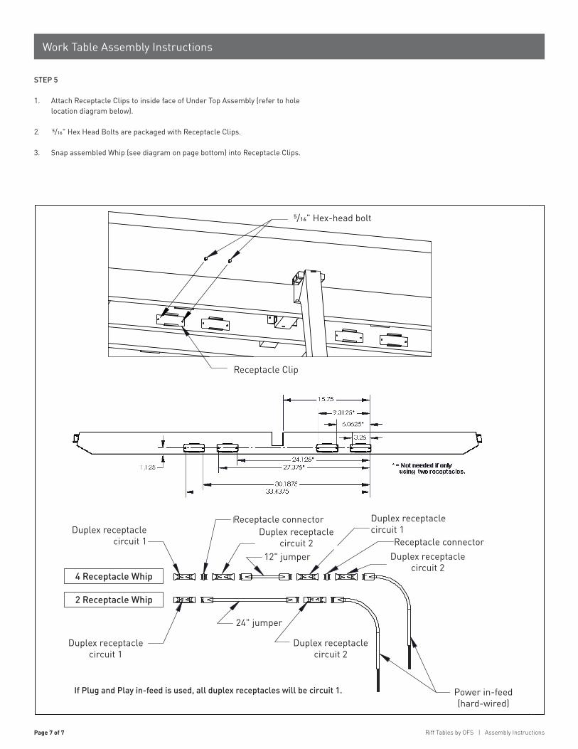
STEP 5
1. Attach Receptacle Clips to inside face of Under Top Assembly (refer to hole location diagram below).
2. 5/16" Hex Head Bolts are packaged with Receptacle Clips.
3. Snap assembled Whip (see diagram on page bottom) into Receptacle Clips.
Receptacle clip
5/16" Hex-head bolt
Attach receptacle clips to inside face of under top assembly,• (refer to hole location diagram below)
5/16" hex head bolts are packaged with receptacle clips.•Snap assembled whip (see diagram on page bottom) into receptacle clips•
Duplex receptaclecircuit 1
Receptacle connector Duplex receptaclecircuit 1
Duplex receptaclecircuit 1
24" jumper
Duplex receptaclecircuit 2
Power in-feed(hard-wired)
4 Receptacle whip
2 Receptacle whip
Duplex receptaclecircuit 2
12" jumperReceptacle connector
Duplex receptaclecircuit 2
If Plug and play in-feed is used, all duplex receptacles will be circuit 1.
Series: Part #:Verve X1
Receptacle Clip
Power in-feed (hard-wired)
Duplex receptacle circuit 2
Duplex receptacle circuit 2
Duplex receptacle circuit 2 Receptacle connector
12" jumper
24" jumper
Receptacle connector Duplex receptacle circuit 1Duplex receptacle
circuit 1
24" jumper
Duplex receptacle circuit 1
4 Receptacle Whip
2 Receptacle Whip
If Plug and Play in-feed is used, all duplex receptacles will be circuit 1.
5/16" Hex-head bolt

10.15an OFS Brands™ company | 1204 East Sixth Street | Huntingburg, IN 47542 | 800-521-5381 | ofs.com
PART # 1572705INSTRUCTION SHEET # 2546INS
WORK TABLE ASSEMBLY INSTRUCTIONS
Riff Tables


