35
109 Part two Basic rigging

109
Part two
Basic rigging
111
Chapter 11 Steel erection
Introduction
The use of structural steel in the construction of multi-storey buildings was very common until the
development of concrete reinforced design. Over recent years, however, structural steel design has
started to make a comeback in multi-storey work. Portal frame construction is also widely used for low
rise factories and warehouses. Structural steel is used extensively in the construction of powers stations,
smelters, refineries, bridges, transmission towers, communications towers and other industrial projects.
Certification
Those engaged in (or directly supervising) steel erection must hold a Basic Rigging certificate or equivalent
old certificate.
Where steel erection involves multiple crane lifting operations or the use of load equalising gear, the
Intermediate Rigging certificate (or equivalent old certificate) is required. The erection of permanently
guyed structures (such as some communications towers) requires the Advanced Rigging certificate (or
equivalent old certificate).
Trainee riggers who can produce a properly maintained logbook which details at least 25 working days
of practical rigging experience in the erection of steel structures greater than 4m in height, are entitled
to a major reduction in the amount of practical skills assessment needed to qualify for the Basic
Rigging certificate.
Riggers must be familiar with the common erection methods and be able to recognise the typical hazards
associated with this type of work. They must be able to read and understand construction drawings and
specifications. They must also have the skills necessary to use the tools and equipment needed to erect
steel and they must be able to work safely and confidently at heights.
Steel erection
Structural steel is basically a skeleton, designed to support a building. The first section must be fully
plumbed and wind braced to ensure stability for the rest of framework.
As erection progresses, the wind bracing must be fitted. In some ‘A-Frame’ or ‘Saw tooth’ type buildings,
which are long and narrow, the building may have to be guyed for support until each wind brace bay
is erected.
Columns should be guyed to prevent the holding down bolts from pulling out causing the column to
collapse. The concrete in the plinth that the column stands on is usually green.
Guys that are left on overnight must be FSWR guys. Fibre ropes shrink when they are wet and stretch
when they are dry, and are therefore dangerous to use as guys.
The foreman or a competent person should ensure that every column base is level using a theodolite or a
dumpy level before starting to erect the columns. Bush jobs could use a spirit level.
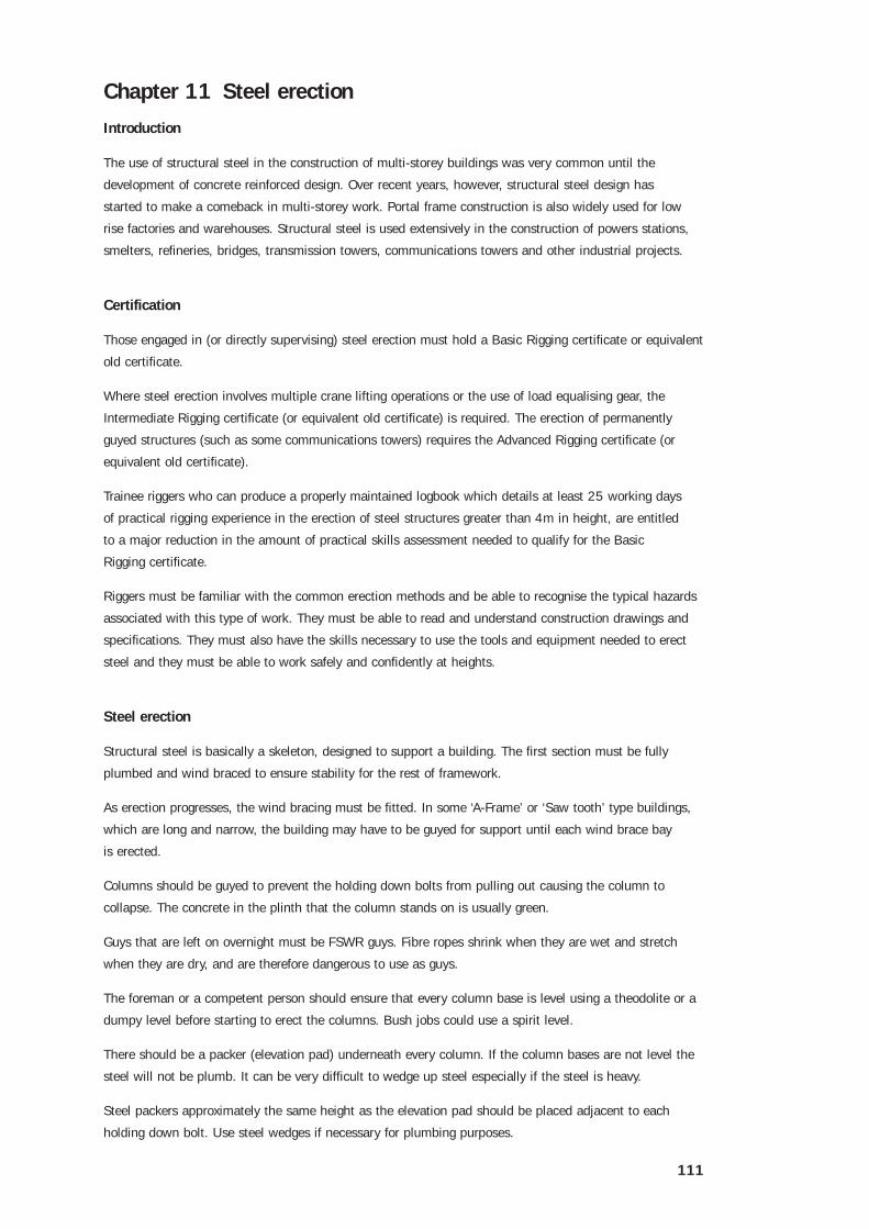
There should be a packer (elevation pad) underneath every column. If the column bases are not level the
steel will not be plumb. It can be very difficult to wedge up steel especially if the steel is heavy.
Steel packers approximately the same height as the elevation pad should be placed adjacent to each
holding down bolt. Use steel wedges if necessary for plumbing purposes.
112
The mass (weight) of any steel must be known for lifting into
place. When ordering cranes to raise columns, a second crane
may be required to ‘float’ in the base.
When raising a column with two cranes at the column head
each crane should be capable of lifting the total weight of the
column. If this is not possible, equalising gear must be used.
To ensure that columns hang vertically they should be slung as
near to the top as possible.
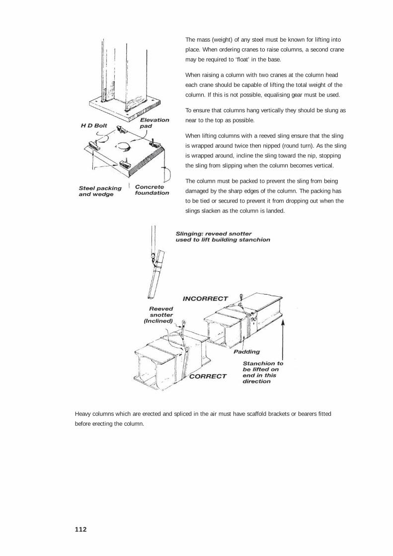
When lifting columns with a reeved sling ensure that the sling
is wrapped around twice then nipped (round turn). As the sling
is wrapped around, incline the sling toward the nip, stopping
the sling from slipping when the column becomes vertical.
The column must be packed to prevent the sling from being
damaged by the sharp edges of the column. The packing has
to be tied or secured to prevent it from dropping out when the
slings slacken as the column is landed.
Heavy columns which are erected and spliced in the air must have scaffold brackets or bearers fitted
before erecting the column.
113
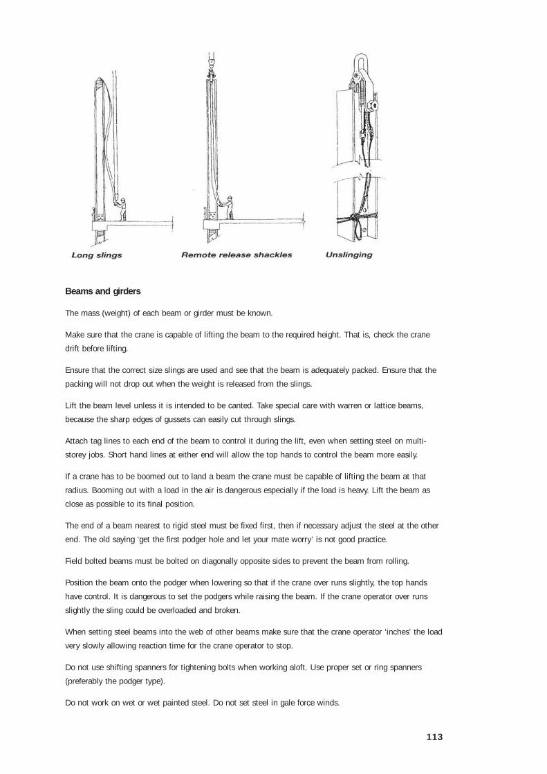
Beams and girders
The mass (weight) of each beam or girder must be known.
Make sure that the crane is capable of lifting the beam to the required height. That is, check the crane
drift before lifting.
Ensure that the correct size slings are used and see that the beam is adequately packed. Ensure that the
packing will not drop out when the weight is released from the slings.
Lift the beam level unless it is intended to be canted. Take special care with warren or lattice beams,
because the sharp edges of gussets can easily cut through slings.
Attach tag lines to each end of the beam to control it during the lift, even when setting steel on multi-
storey jobs. Short hand lines at either end will allow the top hands to control the beam more easily.
If a crane has to be boomed out to land a beam the crane must be capable of lifting the beam at that
radius. Booming out with a load in the air is dangerous especially if the load is heavy. Lift the beam as
close as possible to its final position.
The end of a beam nearest to rigid steel must be fixed first, then if necessary adjust the steel at the other
end. The old saying ‘get the first podger hole and let your mate worry’ is not good practice.
Field bolted beams must be bolted on diagonally opposite sides to prevent the beam from rolling.
Position the beam onto the podger when lowering so that if the crane over runs slightly, the top hands
have control. It is dangerous to set the podgers while raising the beam. If the crane operator over runs
slightly the sling could be overloaded and broken.
When setting steel beams into the web of other beams make sure that the crane operator ‘inches’ the load
very slowly allowing reaction time for the crane operator to stop.
Do not use shifting spanners for tightening bolts when working aloft. Use proper set or ring spanners
(preferably the podger type).
Do not work on wet or wet painted steel. Do not set steel in gale force winds.

114
Tapered drifts should be held by hand when being driven in to stop them being driven right through.
Hammers should have a restraining lanyard to stop them from being dropped from aloft.
Spliced columns have to be aligned directly above one another when being positioned.
When landing a beam experienced riggers will push a drifting beam across and drop their podgers in.
To lift a beam at the centre by two cranes with a mass greater than the capacity of either crane, use a
properly rigged, equalising bridle or equalising beam.
The WLL must be stamped on all lifting gear including equalising beams, shackles, rings and hooks.
Before lifting bowstrings, turnbuckles and rigging screws should be fitted to long beams which may flex
excessively. The screws must be fitted with a locking device or preventer lashings.
Roof trusses, lattice girders, purlins and girts
Check the following before attempting to lift roof trusses into position:
• the mass (may have to be calculated)
• the truss points must be properly bolted or riveted.

115
Roof trusses or lattice girders must not be left standing unsupported in an upright position. They should
be secured by lashing or tomming to a building column or another suitable anchorage.
Lifting puts a force on a roof truss that is the opposite to those the truss was designed to take. The
bottom chord is only designed to take tension.
When lifting by the top chord, the bottom chord is in compression and can buckle and bend. To stop this
strengthen the bottom chord with a strongback or bow strings. Bending in saw tooth trusses which are
used mostly for short spans is not as great.
Trusses should always be lifted at the panel points. Make sure that the slings are protected by packing to
stop them being cut by the sharp edges of the gusset plates.
Principal high pitched gable trusses should be slung directly at the apex.
Flat pitched gable roof trusses are particularly dangerous to lift. They should be bridled and slung with
a central vertical sling. The mass should be evenly distributed to the slings and the crane must have a
greater drift.
To maintain control, attach the holding down bolts and fit tag lines to the ends before lifting the truss into
its final position.
Fit temporary guys to the apex of the first truss. Four guys should be fitted if the truss exceeds 10m in
length. Do not remove the guys until the wind bracing is fitted.
Finish the first bay completely before continuing erection of the rest of the building.
When pulling up the purlins and braces by hand, pull up the purlins first so that the braces can then be
fitted underneath. Braces which are fitted first get in the way when trying to pull up the purlins.
Fit the bottom girts first to allow standing room. The girts can be lifted using a gantline or tackle slung off
the eaves girder.
Wedge open the angles with wooden wedges to help the top hands enter the braces onto the gusset plates
when using double angle knee bracing. The wooden wedges should be lashed to the bracing so that they
cannot fall if they drop out.
Do not use both hands to force or podger any steel into place when working aloft.
Bolts, nuts and washers
There is a huge variety of fastenings available for structural connections. The rigger must know which
fastenings have been specified by the structural designer for the various members. This involves a careful
reading of the drawings and specifications.
Riggers must also be able to recognise different grade, diameter and length fasteners by visual inspection.
If the wrong bolts are used the strength or stability of the steel structure can be seriously affected.
116
Bolts
Structural bolts are generally categorised by their nominal diameter, overall length and thread length. The
nominal bolt diameter in millimetres is designated with the letter M followed by a number. For instance,
an M 16 bolt has a nominal diameter of 16mm.
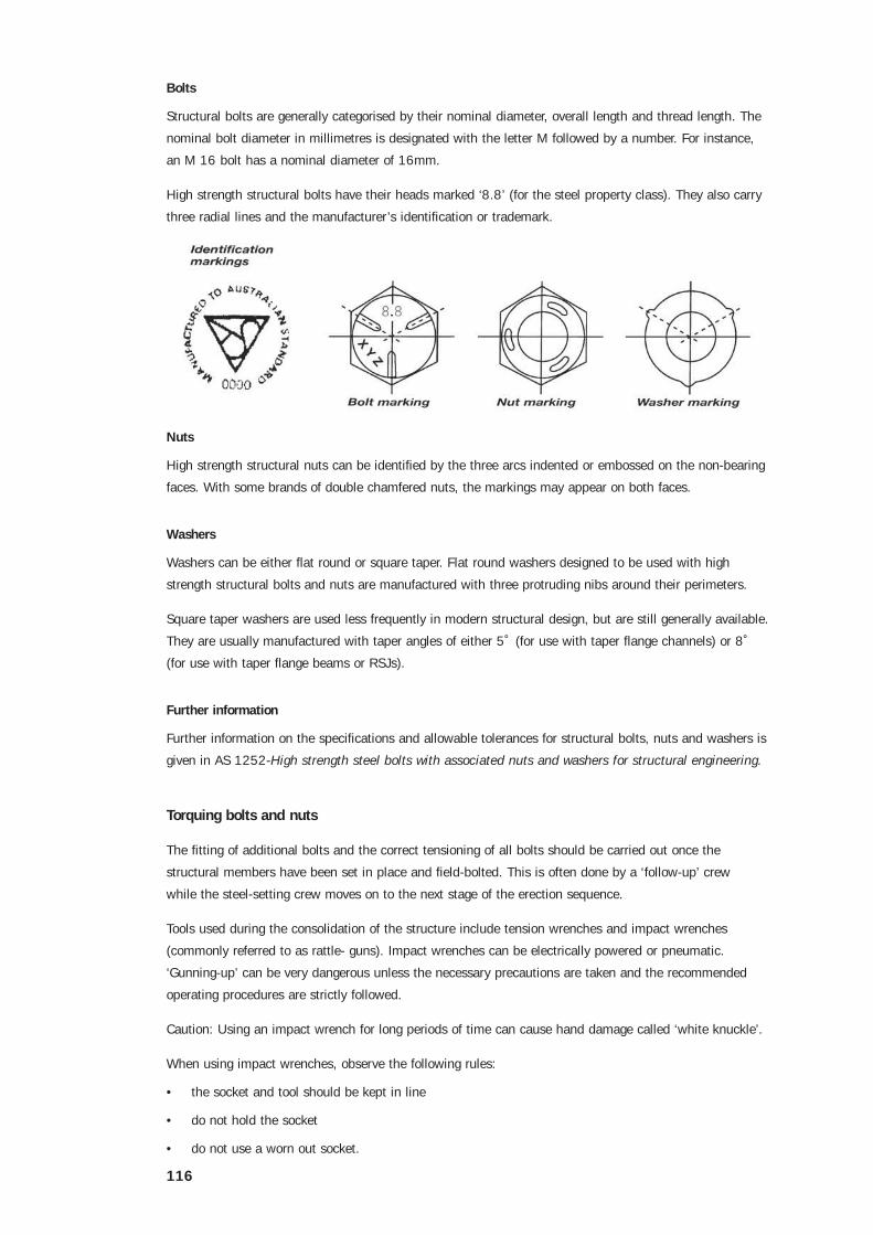
High strength structural bolts have their heads marked ‘8.8’ (for the steel property class). They also carry
three radial lines and the manufacturer’s identification or trademark.
Nuts
High strength structural nuts can be identified by the three arcs indented or embossed on the non-bearing
faces. With some brands of double chamfered nuts, the markings may appear on both faces.
Washers
Washers can be either flat round or square taper. Flat round washers designed to be used with high
strength structural bolts and nuts are manufactured with three protruding nibs around their perimeters.
Square taper washers are used less frequently in modern structural design, but are still generally available.
They are usually manufactured with taper angles of either 5˚ (for use with taper flange channels) or 8˚
(for use with taper flange beams or RSJs).
Further information
Further information on the specifications and allowable tolerances for structural bolts, nuts and washers is
given in AS 1252-High strength steel bolts with associated nuts and washers for structural engineering.
Torquing bolts and nuts
The fitting of additional bolts and the correct tensioning of all bolts should be carried out once the
structural members have been set in place and field-bolted. This is often done by a ‘follow-up’ crew
while the steel-setting crew moves on to the next stage of the erection sequence.
Tools used during the consolidation of the structure include tension wrenches and impact wrenches
(commonly referred to as rattle- guns). Impact wrenches can be electrically powered or pneumatic.
‘Gunning-up’ can be very dangerous unless the necessary precautions are taken and the recommended
operating procedures are strictly followed.
Caution: Using an impact wrench for long periods of time can cause hand damage called ‘white knuckle’.
When using impact wrenches, observe the following rules:
• the socket and tool should be kept in line
• do not hold the socket
• do not use a worn out socket.
117
Working aloft
Background
In the past, steel erectors were often expected to work at heights with nothing to protect them from falling
except a sense of balance and a lot of luck. Shinning up and sliding down steel columns, walking the top
flange of narrow beams, running purlins up roof trusses and riding crane lifted loads were often regarded
as standard work practices.
Not surprisingly, this lead to high fatality and injury rates among steel erectors.
Since the introduction of modern occupational health and safety laws by the Australian States and
Territories, the old methods of working at heights are no longer acceptable.
Minimising the risks
Careful planning can and should reduce the amount of work needed to be carried out at heights. Where
space permits and cranes of sufficient capacity are available, entire sections of the structure can be
prefabricated on the ground. Using remote release shackles wherever possible can also reduce the
need to work at heights.
On large scale industrial projects and bridges, it is often possible to fix scaffolds to structural members or
sections of the structure before they are lifted into position. Despite these and other measures, many of
the rigger’s tasks need to be carried out at heights.
Wherever working aloft is necessary, the work method and means of access should minimise the risk of
falling, and the risks to other people in the vicinity.
The area below the work should be barricaded or cordoned off to prevent unauthorised access by other
workers or the general public. Where this is not possible, overhead protection decks such as temporary
gantries, covered ways, cantilevered catch platforms, perimeter safety screens or debris nets may be
necessary.
All hand tools (such as podgers, ring-spanners, drifts and hammers) should be securely stowed on a
purpose designed rigger’s belt constructed from sturdy leather, canvas webbing or synthetic webbing.
Where safety harnesses are used, these generally incorporate loops for the stowing of tools. Bolts, nuts
and washers should be kept in a pouch attached to the belt. One handed flogging hammers should be
fitted with wrist straps.
There are many ways of providing steel erectors with a safe working platform and safe means of access
which can prevent dangerous falls.
These include the use of:
• elevating work platforms (EWPs) such as scissor hoists, travel towers and boom lifts
• scaffolds
• portable ladders
• crane lifted work boxes
• industrial safety nets
• safety line systems.
Safety line systems require a high degree of planning, training and supervision and rely heavily on the
steel erector always ‘doing the right thing’ and not taking short cuts. For these reasons, they should only
be used where none of the other methods are practicable.
118
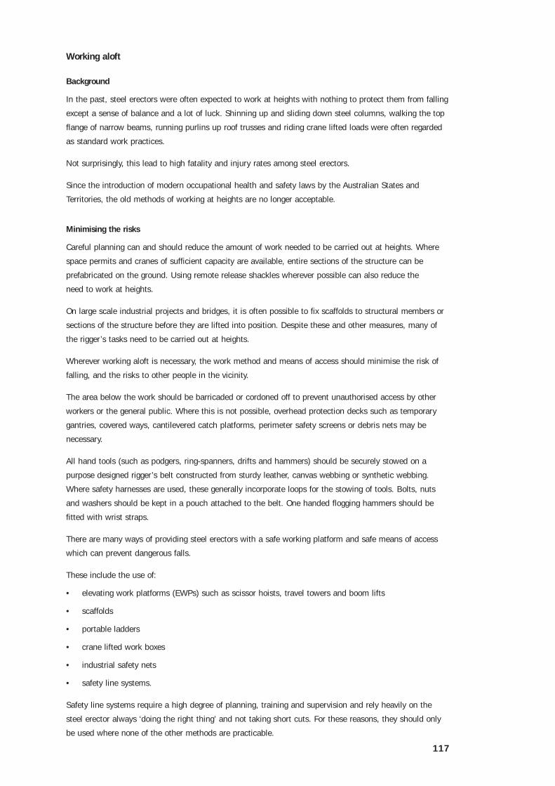
The static line should belocated at least 2.1 mabove the beam, as statedon page 142, and lanyardsshould be connected to therear D-ring between theshoulder blades.
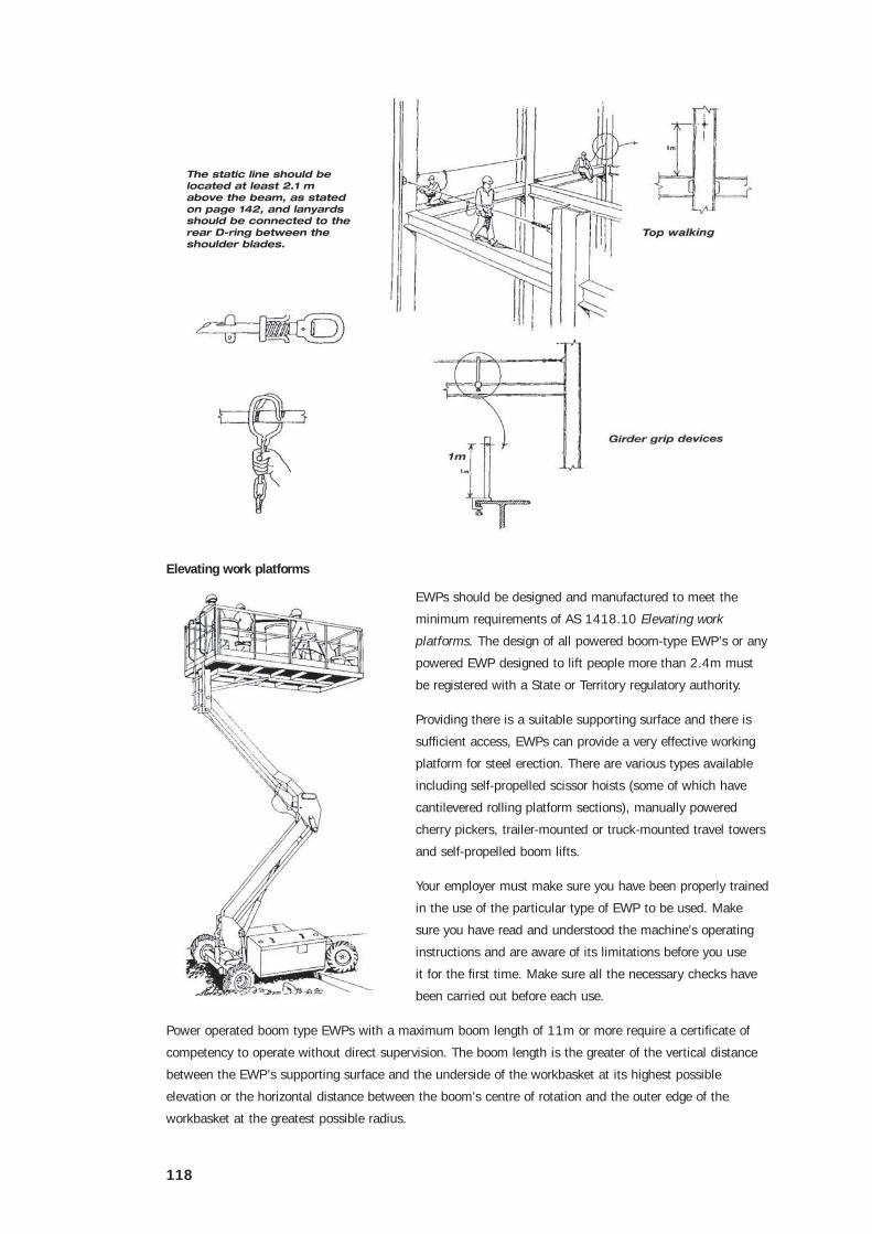
Elevating work platforms
EWPs should be designed and manufactured to meet the
minimum requirements of AS 1418.10 Elevating work
platforms. The design of all powered boom-type EWP’s or any
powered EWP designed to lift people more than 2.4m must
be registered with a State or Territory regulatory authority.
Providing there is a suitable supporting surface and there is
sufficient access, EWPs can provide a very effective working
platform for steel erection. There are various types available
including self-propelled scissor hoists (some of which have
cantilevered rolling platform sections), manually powered
cherry pickers, trailer-mounted or truck-mounted travel towers
and self-propelled boom lifts.
Your employer must make sure you have been properly trained
in the use of the particular type of EWP to be used. Make
sure you have read and understood the machine’s operating
instructions and are aware of its limitations before you use
it for the first time. Make sure all the necessary checks have
been carried out before each use.
Power operated boom type EWPs with a maximum boom length of 11m or more require a certificate of
competency to operate without direct supervision. The boom length is the greater of the vertical distance
between the EWP’s supporting surface and the underside of the workbasket at its highest possible
elevation or the horizontal distance between the boom’s centre of rotation and the outer edge of the
workbasket at the greatest possible radius.
119
Note: With the introduction of the nationally uniform certificates, some States and Territories have allowed
a phase-in period for this certificate class. If in doubt, check with the local certifying authority.
Observe the following rules when using an EWP:
• make sure the supporting surface has enough load-bearing capacity for the EWP
• do not overload the platform or basket
• do not use the EWP on ramps or inclines which are steeper than the supplier’s recommendations
• where fitted, outriggers should be fully extended with pads bearing evenly and the EWP levelled
before being elevated
• for self propelled EWPs, make sure the area of operation is free from obstructions and traps such as
holes, penetrations, drains or upstands. Where these cannot be removed make sure they are securely
barricaded or guarded
• whenever you are elevated, make sure another person who is competent to operate any override
controls is always in the immediate area so you can be quickly retrieved in an emergency. Never work
in total isolation from another person
• make sure you maintain the recommended clearances from powerlines
• do not climb out of, or into the EWP while it is elevated unless the unit has been specifically designed
for this and the supplier’s information allows it
• do not try to gain extra height by climbing up the guardrailing, placing planks on the guardrailing or
placing ladders, trestles or boxes on the platform
• do not use the EWP as an anchorage for lifting gear unless it has specifically designed attachments
for this
• make sure everyone in the basket of a boom type EWP is wearing a safety harness attached to the
anchorages provided within the basket. This may save your life in the event of a boom failure. Do not
disconnect your lanyard until the basket has been fully lowered.
Further information on the selection and safe use of EWPs is given in AS 2550 Cranes-Safe use Part 10,
Elevating work platforms.
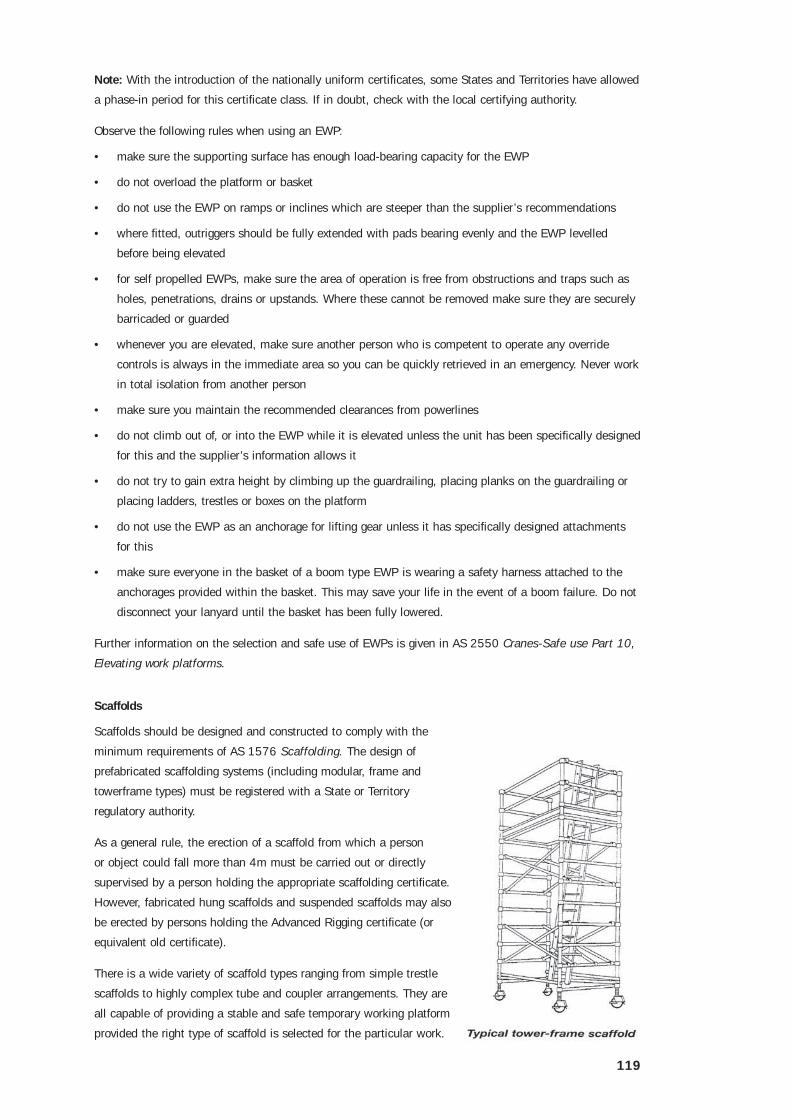
Scaffolds
Scaffolds should be designed and constructed to comply with the
minimum requirements of AS 1576 Scaffolding. The design of
prefabricated scaffolding systems (including modular, frame and
towerframe types) must be registered with a State or Territory
regulatory authority.
As a general rule, the erection of a scaffold from which a person
or object could fall more than 4m must be carried out or directly
supervised by a person holding the appropriate scaffolding certificate.
However, fabricated hung scaffolds and suspended scaffolds may also
be erected by persons holding the Advanced Rigging certificate (or
equivalent old certificate).
There is a wide variety of scaffold types ranging from simple trestle
scaffolds to highly complex tube and coupler arrangements. They are
all capable of providing a stable and safe temporary working platform
provided the right type of scaffold is selected for the particular work.

120
Steel erectors can often make use of scaffolds which have been set up for other work tasks such as wall
cladding, bricklaying, concreting, roof work or services installation.
Scaffolds can also be provided specifically for the setting of steel and associated consolidation tasks such
as welding, insulation and sheeting. These may include bracket scaffolds attached to large structural
members, perimeter safety screens, formwork shutters or large storage tanks, trestle scaffolds for low level
work, cantilevered or spurred scaffolds projecting from the face of the structure, purpose designed hung
scaffolds, and suspended scaffolds such as swing stages, work cages and boatswain’s chairs. One of the
most common forms of scaffolding used during the erection of low rise portal frame buildings and modern
structural design multi-storey construction is mobile prefabricated tower frame scaffolds.
Observe the following rules when using scaffolds:
• make sure the scaffold has been completed and is ready for use. Carefully read all tags or notices
attached to the scaffold. Make sure it has been provided with properly secured means of access such
as single ladders or temporary stairways
• on a mobile scaffold, make sure the lower access ladder is clear of the supporting surface
• make sure the operational area for a mobile scaffold is a hard, flat surface free of penetrations or
obstructions which could destabilise the scaffold during relocation
• do not place a mobile scaffold closer than 1m to a slab edge, penetration or step down unless a fixed
barrier is in place to prevent it crossing that point
• if the supporting surface for a mobile scaffold is sloped, make sure the scaffold is fitted with
adjustable castors with brakes and use the adjustment to level the scaffold before use. Where the
surface gradient exceeds 50, separate adjustable baseplates or similar must be used to take the load
off the castors while the scaffold is in use
• make sure all approaches, access points and platforms have effective lighting without glare or deep
shadows
• do not interfere with a scaffold by removing ties, braces, guardrailing, platform planks, toeboards or
other members. Any alterations needed to the scaffold must be carried out or directly supervised by a
person with the appropriate certificate of competency
• apply the wheel brakes to the castors of a mobile scaffold before use. Do not release the brakes while
anyone is on the scaffold
• do not climb up the framework of the scaffold. Use the access provided
• make sure the access ladder of a tower frame scaffold is always on the inside of the scaffold with the
access opening in the working platform protected by a hinged trapdoor, sliding hatch or similar
• make sure that, wherever a person or object could fall more than 2m, rigid guardrails, midrails and
toeboards are securely fixed to the edges of all platforms and ladder landings
• do not attach shade cloth or other sheeting to a scaffold unless you know it has been designed for the
extra deadloading and windloads
• do not use the scaffold as an anchorage for lifting gear unless it has been designed for the
additional loading
• do not overload the working platforms. If you are unsure of the scaffold’s duty classification, assume it
is light duty. The maximum allowable light duty loading is 225kg per platform per bay. This includes
the weight of persons and materials
• any materials and equipment deposited on working platforms should be positioned to maintain clear
unobstructed access along the full length of the platform at all times

121
• maintain platforms in a tidy condition by frequently removing surplus material and debris
• where platform decking units are constructed from aluminium gridmesh and the material or tools you
are using could fall through the gaps in the gridmesh, cover the platform surface with non-slip sheets
of plywood
• do not try to gain extra height by climbing on the guardrailing, placing planks across the guardrails or
placing a step ladder or trestle on the working platform
• do not move a mobile scaffold while anyone is on it unless the scaffold has been specifically designed
to allow for this
• when relocating a scaffold by crane, make sure it is slung from the base and that the slings are long
enough to enclose the scaffold. Additional scaffold tubes may need to be fixed to provide suitable
lifting points. For large scaffolds, a purposedesigned lifting frame may be required to prevent the
scaffold from distorting during lifting. Make sure all members are secure against dislodgment and all
loose materials have been removed from the platforms.
Further advice on the selection, use and inspection of scaffolds is given in AS 4576 Guidelines for
Scaffolding. Guidance on the erection of fabricated hung scaffolds and suspended scaffolds is given in
Chapters 21 and 22 of this Guide.
Portable ladders
Portable ladders should be designed and constructed to meet the minimum requirements set out in
AS 1892 Portable ladders.
Portable ladders are available in two grades – Industrial and Domestic. Never use a domestic grade ladder
for industrial use because it is not required to be as robust and strong as an Industrial Grade ladder.
Ladders can be constructed from steel, aluminium, timber or reinforced fibreglass and are generally
classified as being one (or a combination) of the following types:
• Single ladders, available in lengths of up to 9m.
• Extension ladders, in two or more stages and available in maximum working lengths of up to 15m.
• Stepladders, available in lengths of up to 5.5m.
• Trestle ladders, used to support scaffold planks and available in lengths of up to 5m.
Trestle ladders are not generally suitable for steel erection but the other types of portable ladders can often
be used for unslinging beams and for bolting up structural members.
Ladders can be checked for serviceability by:
• taking each end of the ladder in turn and trying to push the stiles apart and then together. Movement
indicates insecure rungs or loose tie rods
• laying the ladder flat, raising one end and attempting to push one stile while pulling the other. If the
stiles move relative to each other, the rungs are loose
• tapping timber rungs with a mallet. A dull sound indicates a defective rung.
Damaged or unsound ladders should not be used until they have been repaired and passed re-inspection.
Do not use a ladder with any of the following faults:
• timber stiles warped, splintered, cracked or bruised
• metal stiles twisted, bent, kinked, crushed or with cracked welds or damaged feet

122
• rungs, steps, treads or top plates which are missing, worn, damaged or loose
• tie rods missing, broken or loose
• ropes, braces or brackets which are missing, broken or worn
• timber members which, apart from narrow identification bands, are covered with opaque paint or
other treatment that could disguise faults in the timber.
When using portable ladders, observe the following rules:
• place single and extension ladders at a slope of four to one, and set up step ladders in the fully
opened position
• do not handle or use ladders where it is possible for you or the ladder to make contact with power
lines. In particular, metal or metal-reinforced ladders must not be used in the vicinity of live electrical
equipment
• do not set up a ladder within the arc of a swinging door
• single and extension ladders should be footed by another person or secured top and bottom
• do not use a step ladder near the edge of an open floor or penetration. If the ladder topples, you
could fall over the edge
• do not set up ladders on scaffold platforms or EWPs to gain extra height
• always have two hands free to ascend and descend the ladder. Any materials or tools which cannot
be safely stowed on your belt should be independently transferred or hoisted to the work location
• always face the ladder when climbing or carrying out work
• your feet should never be higher than 900mm from the top of a single or extension ladder, or the
third tread from the top plate of a step ladder
• do not have more than one person on the ladder at any time
• do not work over other people
• make sure there is no danger of crane lifted loads trapping or striking you
• do not overreach. Your belt buckle should be within the ladder’s stiles throughout the work
• do not use a ladder for work involving restricted vision or hot work (such as welding or oxy-cutting)
• the use of power tools on a ladder should be limited to tools which are easily operated one handed
• when working from a single or extension ladder, make sure you can brace yourself at all times.
Further advice on the selection and use of ladders is given in AS 1892.4 Selection, safe use and care of
portable ladders.
Crane lifted work boxes
Crane lifted work boxes are often suitable for very high work or isolated parts of the project where it is
difficult or impractical to provide scaffolds or EWPs.
The work box must be specifically designed for the purpose of lifting people. The work box design must be
registered with a State or Territory regulatory authority.
The work box must be stamped or be provided with a stamped metal data plate, securely and
permanently attached to it in a prominent position, and providing the following information:
• the maximum hoisted load (kilograms)
• the safe working load (kilograms)
123
• the tare mass (kilograms)
• minimum allowable (rated) crane capacity (kilograms)
• identification reference.
The work box must also be marked permanently and legibly with letters and numerals not less than
25mm high in a colour contrasting with the background, with its safe working load in kilograms.
The work box must be painted in high visibility colours. The lifting slings must be permanently attached to
its lifting lugs with moused shackles, or similar. An access door, if fitted, must only open inwards and be
provided with a means to secure it shut.
The number of people supported in the work box must not exceed the number specified on the side of the
box and, in any event, should not be more than three.
At least one person in the work box must hold a dogging or rigging certificate (or equivalent old
certificate).
Any crane used to lift people in a work box must be:
• fitted with a safety hook
• equipped with controls that return to neutral and stop the crane when released
• equipped with power lowering
• equipped with a lockout control to prevent free fall
• fitted with an uplimit switch on the hoist motion
• fitted with a downlimit switch where the work box is to be lowered below the crane’s
supporting surface.
The following rules must be observed when using crane lifted work boxes:
• use the work box solely for lifting persons and their equipment. Structural members are to be
independently lifted into position
• the crane operator must remain at the controls throughout the operation
• all crane movements must be carried out under power
• when the work box is at the maximum intended radius, the crane’s SWL must be at least twice the
total load of the work box, or 1.5t, whichever is the greater
• there must be an effective means of instant communication between the dogman or rigger in the work
box and the crane operator
• where a mobile crane is used, it must not travel while anyone is in the work box
• every person in the work box must wear a safety harness which is attached to the crane hook or hoist
rope termination or to purpose designed anchorages within the work box
• where it is necessary to carry oxyacetylene cylinders or any flammable liquids, these should be in the
minimum necessary quantities, correctly secured and housed in a compartment separate to the work
box. Make sure a suitable fire extinguisher is carried.
Climbing in and out of work boxes at heights can be a dangerous practice. However, where there is no
alternative the work box must be securely attached to the structure before anyone enters or exits.

124
Safety nets
Industrial safety nets are suitable for some types of structures such as bridges and very high portal
frames. They can provide an effective means of fall protection while allowing the steel erectors freedom
of movement on the structural framework. Guidance on the installation and maintenance of safety nets is
given in Chapter 14.
Safety line systems
Safety line systems involve the use of safety harnesses and can include various methods of anchorage
including static lines, life lines and fixed anchorage points for inertia reels or lanyards.
The use of these systems as a primary means of fall protection is not generally recommended and should
only be considered where none of the other methods mentioned previously are practical. Guidance on the
installation and use of safety line systems is given in Chapter 15.
125
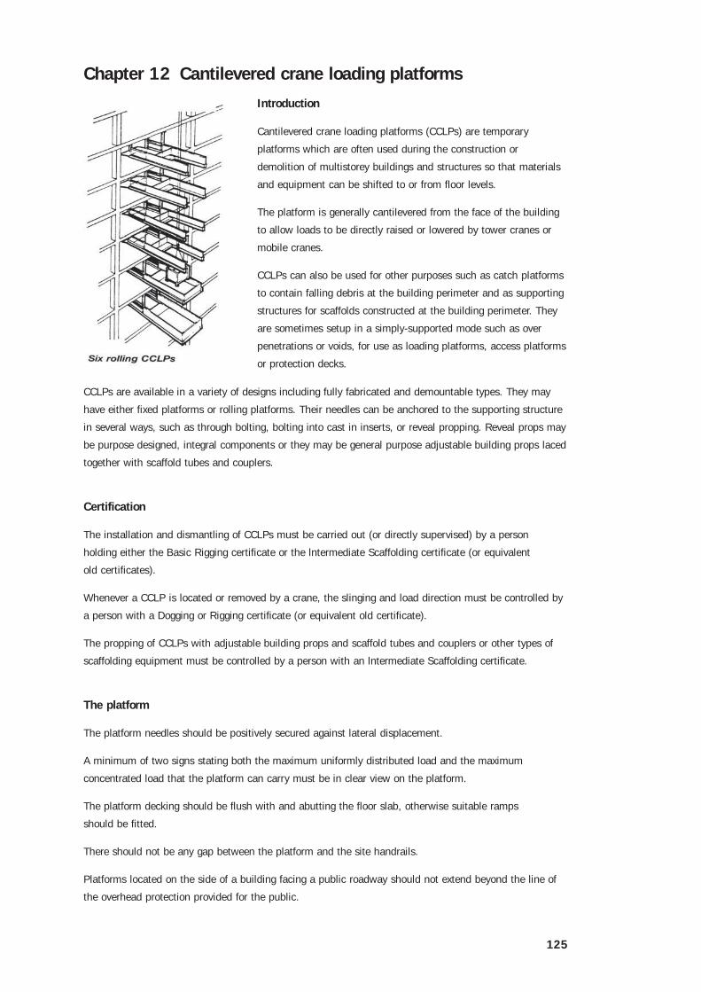
Chapter 12 Cantilevered crane loading platforms
Introduction
Cantilevered crane loading platforms (CCLPs) are temporary
platforms which are often used during the construction or
demolition of multistorey buildings and structures so that materials
and equipment can be shifted to or from floor levels.
The platform is generally cantilevered from the face of the building
to allow loads to be directly raised or lowered by tower cranes or
mobile cranes.
CCLPs can also be used for other purposes such as catch platforms
to contain falling debris at the building perimeter and as supporting
structures for scaffolds constructed at the building perimeter. They
are sometimes setup in a simply-supported mode such as over
penetrations or voids, for use as loading platforms, access platforms
or protection decks.
CCLPs are available in a variety of designs including fully fabricated and demountable types. They may
have either fixed platforms or rolling platforms. Their needles can be anchored to the supporting structure
in several ways, such as through bolting, bolting into cast in inserts, or reveal propping. Reveal props may
be purpose designed, integral components or they may be general purpose adjustable building props laced
together with scaffold tubes and couplers.
Certification
The installation and dismantling of CCLPs must be carried out (or directly supervised) by a person
holding either the Basic Rigging certificate or the lntermediate Scaffolding certificate (or equivalent
old certificates).
Whenever a CCLP is located or removed by a crane, the slinging and load direction must be controlled by
a person with a Dogging or Rigging certificate (or equivalent old certificate).
The propping of CCLPs with adjustable building props and scaffold tubes and couplers or other types of
scaffolding equipment must be controlled by a person with an lntermediate Scaffolding certificate.
The platform
The platform needles should be positively secured against lateral displacement.
A minimum of two signs stating both the maximum uniformly distributed load and the maximum
concentrated load that the platform can carry must be in clear view on the platform.
The platform decking should be flush with and abutting the floor slab, otherwise suitable ramps
should be fitted.
There should not be any gap between the platform and the site handrails.
Platforms located on the side of a building facing a public roadway should not extend beyond the line of
the overhead protection provided for the public.
126
Relocation of crane loading platforms
The floor area where the platform is to be moved to, and the floor area where the platform is to be moved
from, should be barricaded to prevent unauthorised persons from entering into the area while the change
is made.
Perimeter fencing must be removed while the change is made.
No person should work near the unfenced perimeter edge unless attached to the building by a
safety harness.
The area below the platform relocation must be barricaded and spotters provided where necessary.
Clear all loose objects from the platform before the platform is lifted by the crane.
Perimeter fencing (handrails) should be replaced immediately after moving the platform.
All bolts must be placed back in the respective vacant holes when erecting or dismantling.
The lifting position must be clearly marked with signs painted on the platforms.
The lifting lugs should be engineer designed to lift the platform.
Props must be correctly secured at the top and also at the base by bolting, welding, or other suitable
securing method to stop any lateral displacement.
The tare weight of the platform must be displayed on the platform.
Some platforms have a rubbish bin inserted under the platform deck. The rubbish bin must be removed
and emptied before the platform is shifted.
A waterproof sheet with instructions should be attached to the platform showing all operational and safety
instructions of how to use, and lift the platform.
Use
Before the platform can be used:
• all bolts or connectors must be secured and tightened in position
• all props must be plumb and have the rear ties in position
• adjustable props must be adjusted to ensure minimal adjustable jack extension
• rear handrails must be in position
• the side panels and gates must be positively fixed in position.
Gates must be closed at all times except for long loads. All platforms must be kept clean and clear of
loose materials.
Platforms should only be used in the manner for which they were designed. Any alterations or different
use of the platforms should be to an engineered design.

127
Rolling platforms
Rolling CCLPs are platforms which can be rolled inside the building and back out again for ease of loading
and unloading.
The two braces at the front of the platform, and the two locking pins on the left and right side must be in
position and secured at all times for lifting, transporting and use as a loading platform.
The tie bar at the rear of the platform is to be used at all times when lifting or transporting the platform.
The spreader bar under the platform is to be secured and in position at all times.
Move the platform deck forward until it connects with the end of the beam. Secure the left and right
side locking pins. Close the gates and place the left and right brace in position. To move the platform
backwards, reverse the procedure.
Further information
For further information on the installation of CCLPs, refer to the supplier’s design specifications and
recommendations for the particular type and model.
The general guidance for the erection of cantilever scaffolds given in AS 4576 Guidelines for Scaffolding,
can also be applied to CCLPs.

128
Chapter 13 Erection of hoists and mast climbers
Introduction
Riggers are required to erect, dismantle and carry out maintenance on various types of hoist. These are
the external guided cantilevered platform materials (one or two barrow) hoist and the mast climbing
work platform. Both types are widely used in the building and construction industry but can also be used
effectively in other industries.
Certification
The installation, dismantling and maintenance of cantilevered platform materials hoists and mast climbers
must be carried out or directly supervised by a person holding either a Basic Rigging certificate or an
Intermediate Scaffolding certificate.
The Basic Scaffolding certificate can only be used where the WLL of the hoist does not exceed 500kg .
A Basic Rigging or Advanced Scaffolding certificate is needed where the WLL is over 500kg.
The cantilevered platform (one or two barrow) materials hoist
Cantilevered platform materials hoists run up and down the outside of the tower and are powered by
electricity or an internal combustion engine. They are designed for the erection of small multistorey
buildings and should be designed and constructed to comply with AS 1418.7 Builder’s hoists and
equipment.
The working height of the platform is 30 metres or less and some have a maximum height of only 16
metres. Check the manufacturer’s specifications.
Under no circumstance can these hoists be used to carry passengers. Only certificated personnel carrying
out erection, dismantling and maintenance can ride on the platform of a materials only hoist. There must
be a notice on the platform clearly displaying the words - NO PERSONS RIDING.
Set up
The hoist must not be set up over a trench or excavation. When setting up near a trench the distance
between the base of the tower and the edge of the trench must be greater than the depth of the trench.
The hoist must not be set up on bricks. It must be set up on solid timber packing. Where outriggers and
screw jacks are fitted they must be tightened to maintain the hoist in a vertical position.
At the base of the tower the handrail must be set back at least 600mm from the working platform to stop
people from leaning over and being hit by the platform coming down.
There must be an effective gate in the handrail such as a moveable or sliding rail to allow access
to the platform.
On the floors above, a handrail must be placed 600mm from the edge of floors to prevent people falling
off. Do not stand inside this barrier unless the platform is at your level.
There must be an overhead guard for the protection of the driver. The hoist must not be set up in front of
any access way to a building unless it is blocked off.
The gap between the platform and building floor must be secured and made of solid timber or metal. The
gap must be no less than 25mm and no more than 100mm. Do not use loose bridging plates.

129
130
If the hoist goes past any window or opening in the building, the opening must be blocked off to prevent
people leaning out and being struck by the platform. Two barrier chains or gates must be in place on
either end of the platform.
The tower must be guyed or tied every 6m and have no more than 3m free standing above the top tie,
irrespective of the working height of the platform. The guys must extend diagonally from the four corners
of the tower and the platform must not foul any guy rope. Guy ropes must be at least 9mm in diameter
for hoists to 500kg capacity and at least 12mm for more than 500kg (and 6 x 19 construction).
Ties must be at least the same strength as the guys and rigid enough to stop the tower flexing. Fibre rope
guys must not be used because they shrink when wet and stretch when dry.
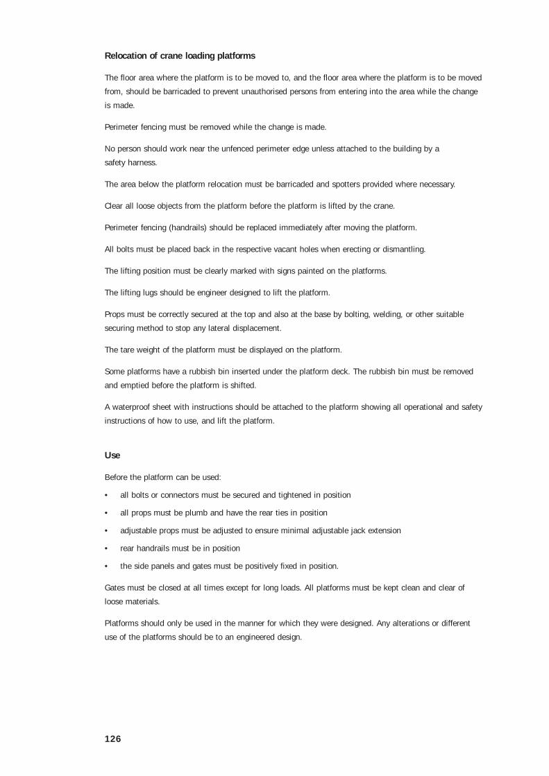
Electrical
If the electrical power lead from the main box is loose it must be
tied up clear of the ground. There have been many serious and fatal
accidents because of leads lying in wet ground becoming entangled in,
or severed by, equipment. All electrical equipment must be protected
against water.
The wire hoisting system
All materials only hoists (cantilevered platform and tower) use a wire
rope hoisting system for raising and lowering the platform.
There must always be at least two turns of wire rope on the hoist
drum. The wire must be fixed mechanically. It must be at least
6 x 19 construction flexible steel wire rope (FSWR) and have no
condemnable defects.
The hoist wire must lie neatly on the drum. Do not allow the wire to show loose turns. In the event of a
rope failure there is a cam or a gripper to stop the platform from falling.
A top limit switch must be installed to stop the platform approaching closer than 1.5m from the head
sheave on the hoist. A floor indicator must be installed where the platform travels more than six floors or
15m or if the driver’s view is obstructed.
Working load limit
The working load limit (WLL) must be displayed on the platform. The hoist WLL will be either a ‘Single
barrow 250kg’ or a ‘Double barrow 500kg’. Do not allow the load to exceed the WLL.
Pre-checks
Prior to operating the hoist, carry out the following pre-checks:
• make sure that the hoist ties are in place and the tower has secure foundations. Check that the tower
is vertical
• the hoist rope must lie neatly on the drum
• the lead from the power source must be secured well clear of the ground and in good order
• the tower guides must be clean and rust free.

131
• the WWL and NO PERSONS RIDING signs must be in place and readable
• the attachment points for the barrier must not be bent or damaged.
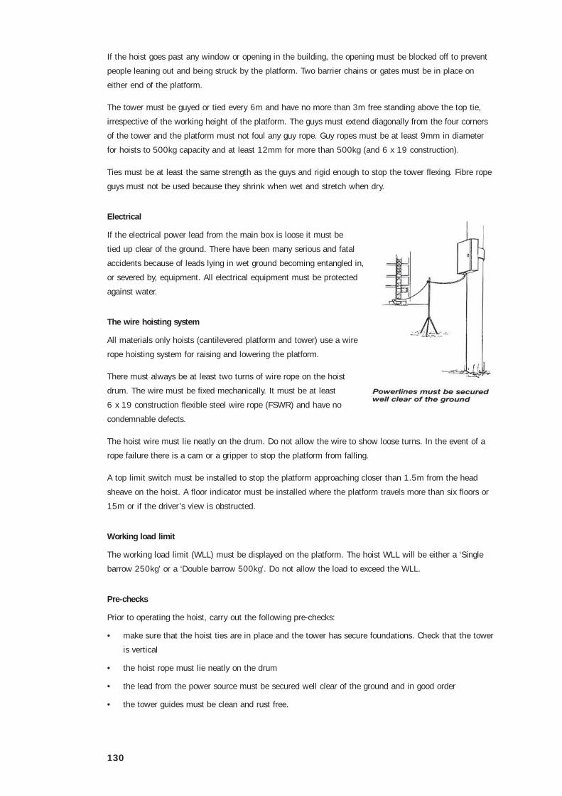
Mast climbers
Design and construction
Mast climbing work platforms should be designed and constructed to comply with AS 1418-10 Elevating
work platforms. The design must be registered with the local regulatory authority.
Mast climbing work platforms are available for use as either freestanding single or multiple tower units
tied to the supporting structure as they are erected.
The supplier’s information for a particular mast climber should:
• confirm that the design has been registered with the local regulatory authority
• include sufficient instructions to enable the rigger or scaffolder to erect, alter and dismantle the unit
safely within its design limitations
• include testing requirements, pre-operational checks and servicing requirements.
Any variation to the supplier’s recommendations should be to an engineered design.
Before preparing to set up a site for mast climbers, the distance from electric power lines must be known.
If the distance is too close the power must be re-routed, the wires covered or the power cut off.
The ground must be checked to ensure that there are no underground services such as large drainage
pipes directly under where the base or outriggers are to be situated.
If a mast climber is to be situated on a suspended concrete slab, the capacity of the concrete slab must
be checked to ensure that it will take the total weight of the loaded machine. The floor must be supported
by propping down the required number of floors, if the concrete is not strong enough. The builder or
person in charge must be able to produce an engineer’s certificate regarding the strength of the
concrete slab.
If the mast climber has to sit on bare ground, the bearing pressure of the ground must be checked to
ensure that adequate packing is provided to support the machine.
The area should be level or the base packed so that it is level before the mast is placed and erected.
The site where erection is to take place should be barricaded or roped off to prevent unauthorised persons
entering the area.
132
Erection
The manufacturer’s manual should be carefully studied before erection starts.
Loose fitting clothes or ties should not be worn as they could be entangled in the moving parts.
Platforms must not be erected or dismantled in high winds.
Base units are fitted with lifting lugs which must be used according to manufacturer’s recommendations
for the various lifting methods used for cranes, fork lift trucks etc.
The base can be either placed with mast outwards for free standing or with the mast inwards where the
mast is tied to the building.
The outriggers must be extended and locked as per manufacturer’s recommendations for the actual setup
of the machine. Packing must be placed under the screw jack feet to distribute the load required for local
ground conditions.
The manufacturer’s recommendations should be checked for the free standing height and jack loadings of
various models.
A free standing mast should not be used in high winds. The mast must be anchored at the top to ensure
stability because high winds can occur suddenly. The building must be checked to ensure that it can
withstand the forces of reaction that may occur in high winds.

133
If the building is not strong enough to support the mast at the top tie position, the anchor (tie) should be
lowered to a point where there is enough strength to provide adequate support. The top anchor is usually
designed so that it can be removed and turned over the top of the mast if the platform is to be driven to
the top.
The platform should be lowered to the lowest position when it is not in use.
Anchoring of masts
Masts which exceed the maximum freestanding height must be tied to the building. When ties are used
the base must be placed so that the mast is toward the building.
Tie spacing must be according to the manufacturer’s specifications or engineer’s design.
The building must be capable of taking the forces imposed by the mast climber at the anchoring points.
The base does not have to be set up on a mobile frame, it may be set up anywhere to suit a
particular need.
If the machine is to be set up on needles on the outside of a building, the set up must be done according
to an engineered design.
134
Chapter 14 Industrial safety nets
Introduction
Industrial safety nets are sometimes used as an effective means of fall protection for those working at
heights where it is not practicable to provide scaffolds or temporary guardrailings. When combined with
overlay nets of finer mesh size, they can also be used to contain falling debris.
Certification
The installation or dismantling of industrial safety nets must be carried out or directly supervised by a
person with either a Basic Rigging or a Basic Scaffolding certificate or old equivalent.
Although safety nets can be attached to, or supported from scaffolds, they are often secured directly to the
structural framework of buildings, bridges, towers and similar structures.
The advantages associated with safety nets include their ability to provide a comparatively inexpensive
means of protecting people from injury due to falling or falling debris without adding considerable loads to
the supporting structure.
Their advantage over individual fall arrest systems such as safety harnesses is that they allow unrestricted
movement for workers.
The disadvantages are that safety nets can suffer from damage or misuse and are vulnerable to
cutting, chafing and damage from sparks. Nets should not be used where they are likely to be
exposed to chemicals.
Manufacture
Safety nets should comply with the design, manufacturing and test requirements of BS 3913, Industrial
Safety Nets.
They are manufactured from synthetic fibre knotted lines with a 100mm mesh size. These lines are
attached to perimeter cords. Safety nets are usually available in sizes of 4m x 3m or larger, and nets can
be joined to cover larger areas.
The label attached to each net will state a maximum fall distance for which the net has been designed.
This will be either 1m or 6m.
Installation
Prior to the installation of a safety net, the intended configuration, method of attachment and strength
of the supporting structure should be verified as adequate by a competent person such as an engineer
experienced in structural design. The verification should be in writing and retained on site until the net has
been dismantled.
In particular, where nets are to be cantilevered from scaffolds, the scaffold must be designed for the
additional loads and additional ties to the scaffold’s supporting structure may be required.
The installation design should include detailed information regarding the exact positioning of the net, the
fixing and tensioning methods and the erection and dismantling procedure.
Where possible, fabrication of the net assembly should be carried out on the ground or on an adjacent
floor and lifted into place with a crane, hoist or purchase.
135
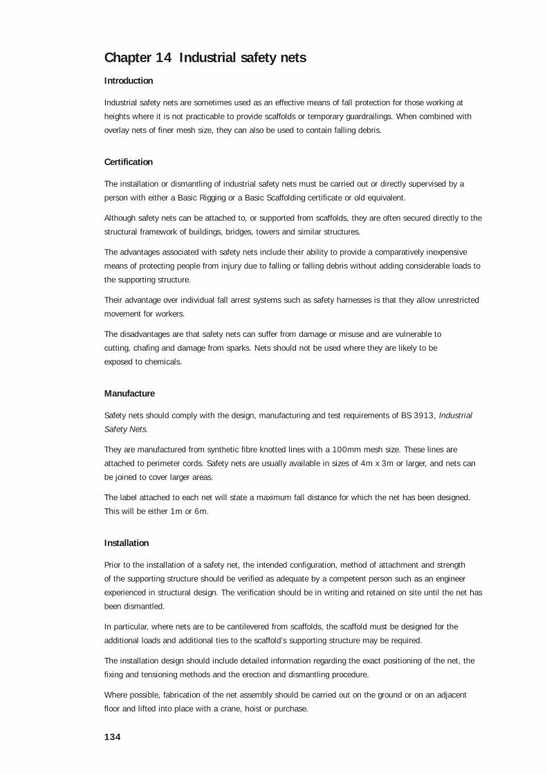
Nets should be installed as close as possible to the working levels and in no case further below than the
maximum fall distance stated on the net’s label.
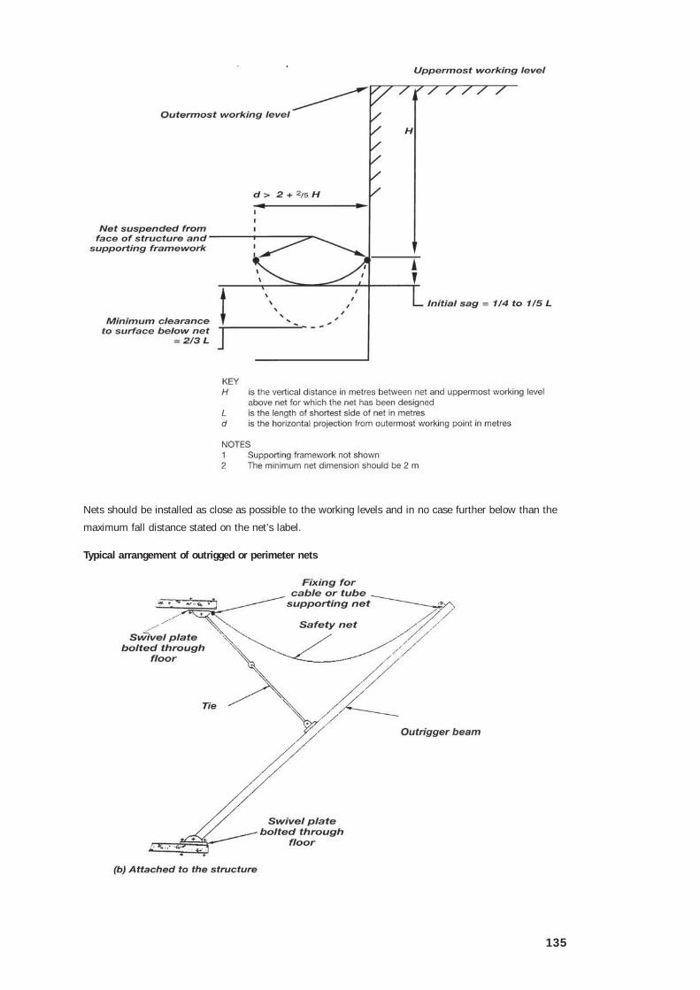
Typical arrangement of outrigged or perimeter nets

136
The gap between a net and the building or structure should be as small as practicable, but never greater
than 200mm.
Nets should not be stretched taut when erected. They should have an unloaded sag of between one
quarter and one fifth of the length of the shortest side.
Sufficient clearance should be maintained at all times below the net to allow for stretch when a person
falls into the net. This clearance should be at least two thirds of the length of the shortest side or 2m,
whichever is greater.
When erected, nets should project beyond the outermost working point a horizontal distance of at least
two fifths of the maximum fall height plus an extra 2m.
Nets should be sited so that a person who has fallen can be quickly rescued. For example, nets erected
adjacent to a working platform, floor or other access point are easily accessible. Where this is not
possible, it may be necessary to cut the net to quickly and safely retrieve a fallen person. Where there is
any possibility of debris falling into the net, the installation design should allow debris clearance which
does not require walking in the net.
Nets should be securely attached to the supporting framework using tie cords, hooks, rings or thimbles
equally spaced at intervals not more than 750mm along each side and at the corners. They should be
fixed to the border cords and adjacent mesh cords of the net.
Where cords are wrapped around sharp edges they should be packed to prevent damage.

137
Use and maintenance
A net which is used for the safety of persons should never be subjected to a loading test. The net should
incorporate test cords which can be removed and tested in accordance with BS 3913.
After a net is put into use, these tests should occur at regular intervals dictated by site conditions, but in
any event, at least every three months.
The test cords should not be used for any other purpose and should remain fixed to the net until they are
required for testing. A record of the test results should be kept.
Nets should be thoroughly examined on both sides by a competent person immediately before they are
erected. When a net is spread out for examination, particular care should be taken to avoid it coming into
contact with cement mortar or other corrosive substances.
The net supporting framework and all anchorages should be inspected by a competent person immediately
following erection, at weekly intervals, and immediately following any incident which may affect the
strength of the net.
It is important that nets are kept free of all debris which may cause injury to persons falling into them.
The following situations should be avoided wherever possible:
• dragging the net over rough surfaces
• contact of cords with sharp edges
• stacking materials on the net
• accumulation of debris in the net
• persons jumping or throwing objects into the net
• sparks or flame from welding or oxy-cutting, hot gases from blow torches and hot ashes from
chimneys or furnaces
• chemical attack
• the supporting framework being struck by moving loads
• unauthorised interference with any part of the net assembly.
Expert advice from the supplier or a competent person should be sought where there is any doubt
regarding the suitability of the net following contamination or severe shock loading. Expert advice should
also be sought on the serviceability of any net which has been in use for two years or more.
Damaged nets should be repaired only by specialists.
When they are not in use, safety nets should be stored under cover where they are protected from the
weather and strong sunlight.

138
Chapter 15 Safety line systems
Safety line systems are used to prevent falls from multi-storey buildings when work has to be carried out
in the absence of safety screens or handrails.
The installer designs the system based on the number of persons on the line at any given time taking into
account whether or not energy absorbing lanyards are to be used and any other restrictions on the use of
the line system.
Riggers and other users of the systems must also be aware of all the restrictions on the system.
Permanent installations must have any restrictions on the use of the system shown on sign posts at the
access points.
Certification
The installation of safety line systems may be carried out or directly supervised by a person with either a
Basic Rigging or a Basic Scaffolding certificate or old equivalent.
Specifications
The safety line system may be purpose designed or the following specifications may be used.
Single spans
For single spans of four to six metres, where no more than two people are on the line at any one time,
and both persons are using lanyards with energy absorbers rated at 600kg (6kN) or less the specifications
are:
• FSWR 10mm diameter (minimum)
• sag – approximately 50mm per meter, ie 6m span – 300mm sag
• anchorage – capable of supporting an imposed load of 4t (40kN)
• tensioning turnbuckles – minimum 16mm diameter threaded section.
Multiple span
The specification for multi-span systems are the same as a single span system with the
following exceptions:
• sag for two or three continuous spans – approximately 30mm per meter, ie 6m spans = 180mm sag
• sag for four or more spans – no minimum sag required but the line should not be over tensioned
• corner supports or intermediate supports where the FSWR is not free to slide through the support end
anchorages (ie they should be capable of supporting an imposed load of 4t).

139
Static line spans
The static line is the supporting safety line attached to the inside of the perimeter columns. The line
should be supported at each column or in accordance with an engineer’s specification.
The line should be placed to eliminate the risk of tripping.
Where practicable the line should be located no less than
2.1 metres above the floor of the work area. The point of
attachment to the safety line system should be within reach of
the user standing on the floor.
Anchorages and lines between supports should be positioned
on the inside face of columns where practicable and used to
anchor static lines, or the static line may pass through a cavity
tube cast in concrete for that purpose.
Static lines between supports must be free of obstructions to allow uninterrupted movement for persons
who may be attached to the line.
If a line passes around a column, corner, or other sharp edge, it should be packed to prevent
damage to the line.
Do not use bulldog grips on static lines.
Tensioning should be achieved by turnbuckles or other appropriate means such as wire rope pullers and
creeper winches.
If ratchet and pawl devices such as creeper winches are used for tensioning, remove them from the
system after tensioning is completed.
Joining static lines
One method of joining static lines:
• terminate one end with a thimble and three double saddle clamps and allow a 200mm tail
• the second line should be passed through using a second thimble and three evenly spaced double
saddle clips allowing a 200mm tail and shackle between each rope end
• line joins should be located at or adjacent to supports or anchorage points
• lapped joins on lines must not be used under any conditions.

140
Line systems for vertical travel
When using vertical lifelines (droplines) or other vertical fall arrest systems in connection with work from
boatswain’s chairs or ladders, only one person should be attached to any one lifeline. Vertical lifelines
should comply with AS 1891-3 Fall arrest devices.
Termination of static lines
The termination of the static line should be by eye and thimble. Where practicable ends should be
secured by one of the following methods:
• double saddle clamps with a minimum of three equal spaces with a minimum 200mm tail past the
last clamp
• hand splice with thimble eye
• machine splice with thimble eye
• suitable wedge sockets
• purpose designed fittings such as swaged or pressed fittings.
Lines and fittings may be secured directly to anchorage points with dee or bow shackles which should
have a minimum WLL of 2t. The pin of the shackle should be moused (lashed) to the shackle.
Installation of anchorage points
Anchorage points used should be located as high as equipment permits, as it is safer to work below the
point of anchorage.
The span between the intermediate supports of static lines should not exceed the engineer’s or supplier’s
specification. All bolts should comply with AS 2317-1984 Collared eyebolts.
The following types of anchorages are acceptable when used in concrete:
• Cast-in anchors (in situ). A wall tie (shee bolt) purpose designed. An engineer designed anchorage
• Chemical and friction type anchors. Chemical and friction type anchorages should be positioned so
the load from a fall is taken in shear. They should be proof tested in tension to at least one third of
the design load prior to use. Collared eye bolts should be used.
All anchorages should be visually checked prior to use.
Turnbuckles
Only framed turnbuckles of an open type design which allow visual inspection of the condition and
extension of the threaded sections should be used.
The frame should be locked or moused to the eye bolt to prevent slackening due to vibration, shock or
spin in the line attached. Hook type turnbuckles should not be used. Only clevis or eye type should be
used on lifelines.
Harnesses, lanyards and equipment
Body type harnesses and lanyards which comply with AS 1891 Industrial safety belts and harnesses
should be used. The harness should be connected to the lanyard or lifeline at the top dorsal position.

141
If a life line and rope grab device is used on steeply sloping surfaces, the user needs to have the device
located in front. This will allow safe manual operation of the mechanism.
Do not connect into a single D-ring on the side of the harness belt. Both side D-rings may be used for
pole straps if a fall of 600mm or more is not possible. Do not use waist type belts.
Safety harnesses should be selected and used in accordance with AS 2626 Industrial safety belts and
harnesses – Selection use and maintenance. Always follow the manufacturer’s information and advice,
if available.
There should be a minimum of slack in the lanyard between the person and the attachment to the
anchorage. The length of the lanyard should restrict the fall distance to a maximum of 1.8m.
Where an anchorage point is above the harness connection point a 1.8m lanyard will achieve this result.
Where the anchorage point is below the harness connection point a shorter lanyard, or other means of
restricting the fall distance may be required.
Do not use home made lanyards. Do not join lanyards together. If extra reach is needed use an inertia reel
or similar equipment.
Do not connect lanyards with inertia reels. Snap hooks or other connectors should have a locking device
and be compatible with all anchorages.
Those using safety harnesses should not work alone. In the event of a fall it is vital that the person is
rescued as soon as possible to prevent further injury by the harness restricting blood flow.
To reduce injuries caused by a fall, energy absorbers should be used as part of the lanyard.
Equipment used with static lines should be compatible with the original system specification, such as
manufactured travellers or energy absorbing lanyards.
Inertia reels
Inertia reel systems can be used to arrest falls where workers are required to carry out their work near an
unprotected edge. They must comply with AS 1891.3 Fall arrest devices.

142
Inertia reels are not designed for continuous support but become effective in the event of a fall. They
should not be used as working supports by locking the system and allowing it to support the user during
normal work. Inertia reels may be less effective for certain applications, eg stopping a person from sliding
down an inclined surface.
When inertia reel anchorages are located lower than head height or a person is located at a horizontal
distance from the anchorage, the line of the inertia reel will strike an edge if the person falls from the
structure. The damage this may cause to the line could result in its failure. To avoid this, inertia reels
should be used in accordance with the manufacturer’s instructions.
Inertia reels may be connected to a static line with a snap hook fitted with a locking device.
Pendulum effect
This is a potential hazard connected with the use of individual fall arrest systems. The pendulum effect
may also occur if the positioning of the inertia reel allows for a significant length of unsupported line
connected to the user.
Swing down can occur if an inertia reel is extended out diagonally so that the line makes an extreme angle
with the perimeter edge of the structure. In this situation, the forces generated in an arrested fall over the
edge will cause the line to rotate back along the perimeter edge until it reaches a position directly in line
with the inertia reel and at right angles with the perimeter edge.
As the line moves back in this way, the unsupported section lengthens, dropping the attached worker
further than the original (arrested) fall distance. If the length of the unsupported line equals the height of
the building then the worker will hit the ground. Even if the worker does not reach the ground they may
collide with obstructions on the side of the building.
To eliminate the pendulum effect place the inertia reel anchorage point square to the position of the line at
the perimeter edge. A mobile anchorage helps here.
143
Chapter 16 Handling pre-cast concrete
Introduction
Pre-cast concrete is commonly used in a wide range of modern building and construction projects. Pre-
cast concrete includes pre-tensioned beams, pre-cast concrete floor and facade panels.
Certification
The placement of pre-cast concrete must be carried out or directly supervised by a person holding a Basic
Rigging certificate or old equivalent.
Work associated with tilt up panels is covered under the Intermediate Rigging certificate but excluded from
the Basic Rigging certificate. For tilt up panels see Chapter 17.
Pre-stressed concrete beams
Pre-stressed concrete beams are designed so that stressing strands allows the concrete to hold a given
load over a larger span.
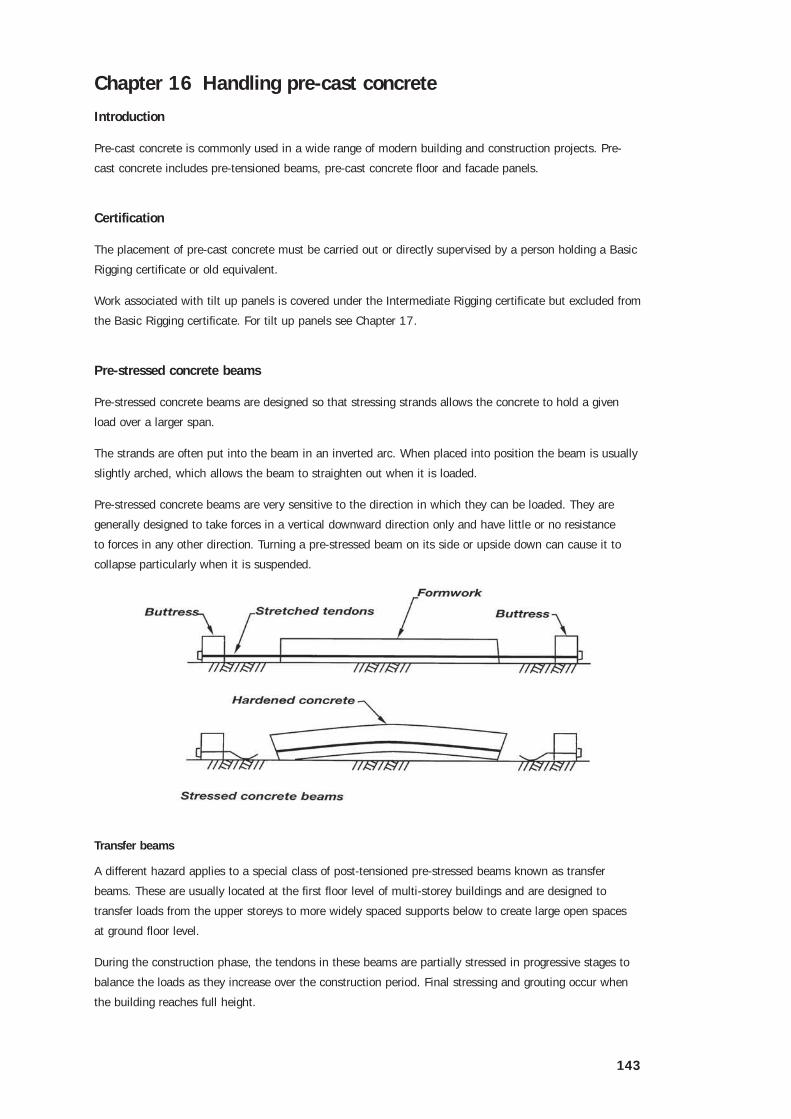
The strands are often put into the beam in an inverted arc. When placed into position the beam is usually
slightly arched, which allows the beam to straighten out when it is loaded.
Pre-stressed concrete beams are very sensitive to the direction in which they can be loaded. They are
generally designed to take forces in a vertical downward direction only and have little or no resistance
to forces in any other direction. Turning a pre-stressed beam on its side or upside down can cause it to
collapse particularly when it is suspended.
Transfer beams
A different hazard applies to a special class of post-tensioned pre-stressed beams known as transfer
beams. These are usually located at the first floor level of multi-storey buildings and are designed to
transfer loads from the upper storeys to more widely spaced supports below to create large open spaces
at ground floor level.
During the construction phase, the tendons in these beams are partially stressed in progressive stages to
balance the loads as they increase over the construction period. Final stressing and grouting occur when
the building reaches full height.
144
If no action is taken to reverse the effects of this procedure during demolition, the beam will tend to bow
upward an increasing amount as the load from above is reduced. This can lead to local failure of the
structure at, or just below, the working level. A reverse bending failure and collapse of the beam well
below the working level can cause a collapse of the entire structure.
Riggers must be extremely careful when choosing the slings and lifting equipment because of the dangers
associated with handling pre-stressed concrete beams.
The beams should be lifted by their ends, and from as near as possible to the position where they are to
be placed.
It is recommended that a spreader beam is used to lift the beams to avoid having slings at an excessive
angle. Spreader beams should be properly designed by an engineer to the length required and the weight
of pre-stressed concrete beams.
Pre-cast concrete facade panels
Pre-cast concrete facade panels should be delivered to the site sitting on a frame so that they only require
one erection crane and can be top lifted. If they are to be stored on site they should be stored on frames.
They should not be erected in high winds.
Although they are usually erected by specialist contractors, riggers should be aware of the hazards.
The lifting inserts must be cleaned out to ensure that the lifting media can be fully bolted.
The lifting media (lugs etc) must be to an engineered design.
Panels should be lifted with a spreader beam so that the pull on the inserts is direct.
The angle between the slings during lifting should not be more than 60˚.
Do not work under the panel to put slings around it, if an insert pulls loose.
Contact the panel manufacturer and/or designer to have the insert positively fixed (welded) to the
reinforcing steel if it is loose.
People who work outside a handrail, or if a handrail is removed, must be attached to a lifeline and be
wearing a safety harness.
One person is to be in charge of the crane when lowering a panel into position.
The crane operator must be instructed to lower as slowly as possible when lowering a panel into
final position.
When lowering panels by radio, if any person under any circumstances cuts across the channel, operations
must stop until their reason for cutting across is discussed. If that reason is not safety they must be
informed not to repeat an extreme safety breach.
Operations must cease immediately if the radio channel being used for giving directions for lowering a
panel is cut into from a person not involved in the operation.


