RIGMASTER POWER AUXILIARY POWER UNIT OWNERS MANUAL 2003 MODEL – RMP-P10-4 Congratulations on your purchase of the RigMaster Auxiliary Power Unit. RigMaster is a totally self contained, stand-alone AC generator, Air Conditioner and Heater System. The only items that are shared with your Truck Systems are fuel and battery supply. The RigMaster unit also trickle charges the Truck batteries while in operation. Superior design and performance have been incorporated into this product to give you trouble-free, economical operation. We are confident you will be satisfied with your new RigMaster Auxiliary Power Unit. The following pages contain design features, principles of operation, preventative maintenance procedures and trouble shooting guides. Please review it carefully prior to starting and operating your RigMaster Unit. Should you have any questions or concerns, please contact your nearest authorized RigMaster Power Dealer, or International Power System Inc. Product Support Group at: 1-800-249-6222
Transcript
RIGMASTER POWER
AUXILIARY POWER UNIT
OWNERS MANUAL
2003 MODEL – RMP-P10-4
Congratulations on your purchase of the RigMaster Auxiliary Power Unit. RigMaster is a totally self contained, stand-alone AC generator, Air Conditioner and Heater System. The only items that are shared with your Truck Systems are fuel and battery supply. The RigMaster unit also trickle charges the Truck batteries while in operation. Superior design and performance have been incorporated into this product to give you trouble-free, economical operation. We are confident you will be satisfied with your new RigMaster Auxiliary Power Unit. The following pages contain design features, principles of operation, preventative maintenance procedures and trouble shooting guides. Please review it carefully prior to starting and operating your RigMaster Unit. Should you have any questions or concerns, please contact your nearest authorized RigMaster Power Dealer, or International Power System Inc. Product Support Group at:
1-800-249-6222
(2)
TABLE OF CONTENTS •
• • •
• • • • • •
• • • • •
• • • •
• • • • • • • •
• •
Principals of Operation: Heater 3 Air Conditioner 5 110 Volt Generator 6
Pre-Start Inspection 7 Control Panel Description and Operating Procedures 8 Fuel System Description and Bleeding Procedures 15 Preventative Maintenance Schedules 19 Consumable Parts Cross Reference List 20 Normal Maintenance and Adjustments Instructions:
Oil Change Instructions 21 Generator Belt Removal/Adjustment 22 Compressor Belt Removal/Adjustment 23 Fan Belt Removal/Adjustment 24 Breakers Reset Instructions 25
Main Components and Part Locations 26 Cleaning Instructions 27 Trouble Shooting Guide 30 Warranty: 32
12 Month Warranty Coverage 32 Warranty Obligations 32 Maintenance 33 Installation 34 Non-Warrantable Items 34 Limitations of Warranty 34 Indemnity 35 Transfer of Warranty 35
Maintenance Record 36 Notes 41
(3)
HEATER, AIR CONDITIONER, 110V GENERATOR HEATER The RigMaster heating system is fully automatic. A constant comfort zone is maintained with the temperature selector (see Climate Control Operation - Page 11). The bunk heating system has a capacity of 12,000 BTU's. This is a closed,stand-alone system that is not integrated into the vehicle's cooling system. When heat is selected, and the RigMaster is in operation, the hot coolant flows through the heat core (installed under the bunk see Figure 1). The heater/air conditioner blower motor (fan) circulates the cab air through the heater core pushing warm air into the bunk area. The coolant is then re-circulated back to the RigMaster Unit. NOTE: PLUGGING IN THE BLOCK HEATER PLACES A LOAD OF APPROXIMATELY 1,500 WATTS ON THE ENGINE, THIS LOAD ENABLES THE ENGINE TO HEAT THE COOLANT. When the coolant temperature reaches 82 degrees C (180 degrees F) an internal bypass valve will open, allowing the coolant to flow to the RigMaster's radiator, where the excess heat is dispersed. This system is designed to maximize bunk heating efficiency.
(4)
Legend:
Hot Coolant Supply Cold Coolant System
1) Engine 2) Radiator 3) Fill/Expansion Reservoir 4) Flow Control Valve 5) Heater/Air Conditioner Unit 6) Coolant Control Valve
HEATER - FIGURE 1
(5)
AIR CONDITIONER The RigMaster air conditioner is fully automatic. A constant comfort zone is maintained with the temperature selector setting (see Climate Control Operation - Page 8). The RigMaster air conditioner is a R134A system that is not integrated into the vehicle's existing air conditioning system.
WARNING
ONLY CERTIFIED AIR CONDITIONING TECHNICIANS SHOULD SERVICE THE AIR CONDITIONER.
The compressor installed in the RigMaster pumps the refrigerant gas through the condenser which dissipates the heat and changes the refrigerant from a gas to a liquid. Then the liquid refrigerant passes through a filter (receiver dryer), and then through the evaporator core located in the bunk heater/air conditioner unit. The heater/air conditioner blower motor (fan) then activates and cool, dry air is then forced into the bunk area.
Legend:
High Pressure Gas 1) Refrigerant Compressor High Pressure Liquid 2) Condenser
Low Pressure Gas 3) Receiver Dryer 4) Heater / Air Conditioner Unit 5) Expansion Valve
AIR CONDITIONER - FIGURE 2
(6)
110 VOLT GENERATOR The 4kw heavy duty generator is located at the rear of the RigMaster and is belt driven at 3600 RPM. The generator has two (2) factory supplied cords. One (1) block heater cord (complete with a plug), allows the generator to be plugged into the vehicle's block heater. This ensures that the vehicle's main engine will be warm when starting in cold weather. This also provides a load for the RigMaster's engine that allows the unit to run more efficiently and prolong the RigMaster's service life. The block heater connection uses one (1) - 15 AMP breaker. It is recommended that the RigMaster remain plugged into the vehicle's block heater throughout the winter months. When the RigMaster is not required, the block heater cord can be unplugged and the operator can then plug the vehicle into a conventional power source. A second 15 AMP supply of 110V power is supplied for the owner/operator convenience. A multiple outlet cord is supplied and can be installed in the bunk area of the vehicle to provide power for 110V appliances.
GENERATOR - FIGURE 3
Each 15 Amp Breake s
NOTE
r has a capacity of 1800 Watt
(7)
PRE-START INSPECTION WITH THE RIGMASTER TURNED OFF 1) Remove the cover. 2) Visually inspect the unit for evidence of oil or coolant leakage. 3) Check the oil and add oil if necessary. 4) Check the tension and wear of all belts. 5) Check the mounting bolts and tighten if necessary. 6) Check for broken, corroded, or loose connectors and/or wires. 7) Check the physical condition and tightness of all hoses and hose clamps. 8) Replace and secure the cover.
(8)
CONTROL PANEL SYSTEM
1
2
6
CONTROL PANEL-FIGURE 4
1. The LCD module display is used to prompt the user through each operating
mode. The display will back light when the user touches any key and will turn off if not used for 30 seconds. If the status light is glowing red the LCD will display an error message directing you to the problem. Please refer to the Error Message Listing for further information.
4
3
5
2. The STATUS light indicates when the cabin controller is active or an error message. While the RigMaster is running the status light will glow green to indicate the system is operating smoothly. The status light will glow red if the system experiences any problems.
3. The POWER key controls whether the module is active. Pushing the
Power key will turn on the LCD backlight and activate the menu display.
4. The MODE key is used to activate the different operational modes. NOTE: Pressing the mode button will back you out of a menu mode but does not save the information inputted when entering operational data.
5. The arrow keys are used to locate the desired data and/or adjust those
values.
6. The SELECT key enters the data and advances the program to the next menu step.
(9)
OPERATION OF THE CABIN CONTROLLER To Turn Power On When the power switch is activated the LCD display will light and show the day of the week and time on the top line and the system status (on/off) as well as the temperature setting on the bottom line. If no keys are pressed, the display panel will then go blank. Clock & Date Set Up It is necessary to enter the time and date programming mode if the module has never been programmed or a different time zone is required. Press MODE key. Press UP or DOWN arrow keys to find SET TIME/DAY/DATE mode on the display. Press SELECT Press UP or DOWN arrow to find SET TIME Press SELECT: Clock hour will start flashing. Press UP or DOWN arrow to adjust Clock hour as required. Press SELECT: Clock hour will stop flashing and Clock minutes will start flashing. Press UP or DOWN arrow to adjust Clock minutes as required. Press SELECT: Clock minutes will stop flashing and am/pm will start flashing. Press UP or DOWN arrow to change as required. Press Mode key for 2 seconds. To Set Date Press MODE key. Press UP or DOWN arrow keys to find Set Time/Day/Date mode on the display. Press SELECT Press UP or DOWN arrow keys to find Set Date mode. Press SELECT: Month will start flashing. Press UP or DOWN arrow keys to find the correct month. Press SELECT: Month will stop flashing and calendar date will start flashing. Press UP or DOWN arrow keys until correct date appears. Press SELECT
(10)
To Set Day Press MODE key. Press UP or DOWN arrow keys to find Set Time/Day/Date mode on the display. Press SELECT Press UP or DOWN arrow keys to find Set Day mode. Press SELECT Press UP or DOWN arrow keys to find the correct day of the week. Press SELECT The correct time and date should now be displayed on the bottom line of the LED. Engine Start Press MODE key. Press UP or DOWN arrow to find Start/Stop Engine mode on the display. Press SELECT The words Start System will display on the screen. Press SELECT The control panel will display the status of the operation as it occurs: after SELECT is pressed the words Glow Plug and a countdown will display on the screen. (The countdown will start at 20 in warm weather or 30 in cold weather situations.) Once the countdown is complete the display will read Cranking as the RigMaster starts up. Once started the control will display Engine Running for 5 seconds and then return to status screen. (Pressing SELECT again will return the display to the status screen immediately.) Engine Stop Press MODE key. Press UP or DOWN arrow to find Start/Stop Engine mode on the display. Press SELECT The words Stop System will display on the screen. Press SELECT The screen will initially display Engine Running and then change to Engine Stopped once the operation is complete. The control will return to the status screen when SELECT is pressed or after 5 seconds.
(11)
Temperature Control Press MODE key. Press UP or DOWN keys to find the Set Temperature mode on the display. Press SELECT Press UP or DOWN keys to find your temperature preference. Note: Temperature control ranges from 65ºF to 85ºF Press SELECT Unless the power is disconnected from the module the system will remember the last set temperature when the RigMaster is turned on. Fan Speed Control Press MODE key. Press UP or DOWN keys to find the Set Fan Speed mode on the display. Press SELECT Press Press UP or DOWN keys to locate automatic, low, medium or high. Press SELECT Each time the RigMaster is turned on a Fan Speed option must be selected or the fan will not run. The air conditioning/heating will start when the fan speed is set. To stop air conditioning/heating the fan speed must be set to OFF. If the system was stopped by another method the air conditioning/heating will start immediately when the system is restarted. Note: If the power was disconnected from the power module the system will forget the fan speed will default to off. Set Alarm Clock Press MODE key. Press UP or DOWN arrow keys to locate Set Alarm Clock mode on the display. Press MODE key for 2 seconds: Alarm Clock hour will start flashing. Press UP or DOWN arrow to adjust Alarm Clock hour as required. Press SELECT: Alarm Clock hour will stop flashing and Alarm Clock minutes will start flashing. Press UP or DOWN arrow to adjust Alarm Clock minutes as required. Press SELECT: Alarm Clock minutes will stop flashing and am/pm will start flashing. Press UP or DOWN arrow to change as required. Press SELECT Press UP or DOWN arrow to turn Alarm clock on. Press SELECT The Alarm symbol will appear on the screen to indicate that the alarm is on. When the alarm clock goes off pressing the SELECT button will cancel the alarm and remove the alarm symbol from the screen. Note: If the alarm is not turned off manually it will ring for 1 minute and then “snooze” for 4 minutes before sounding again.
(12)
AUTOSTART CONTROL OPTION (Must be purchased separately)
AutoStart Option Features Time of Day AutoStart Programming –allows you to program the Auto-start to
the exact time you need your RigMaster to start automatically Day of the Week AutoStart Programming-–allows you to program the Auto-
start to any day of the week you need your RigMaster to start automatically. Automatic Temperature Control Start Up/Shut Down-will start and stop the
RigMaster to regulate the temperature giving you further fuel savings on extended absenses from the cab. Great for pets.
Low Battery Start Up-automatically starts up the RigMaster to charge the truck battery if it gets low. Note:Once the Auto-start feature has been programmed into your RigMaster this feature overrides and replaces the Low-Battery Alarm feature unless this feature is set to off.
Program AutoStart When you purchase the AutoStart Feature you will be provided with a 4 character code which is a series of numbers and/or digits that must be first be programmed in through your control panel before the feature can be used. Press MODE and SELECT at the same time for 3 seconds. Press UP or DOWN to locate the first character in the code Press SELECT to enter the information Continue entering the code in the above manner until all four characters have been selected. Press SELECT to return to the main menu.
(13)
Set Auto Start Timer Press MODE key. Press UP or DOWN keys to locate the AutoStart mode on the display. Press SELECT: SET TIME AUTOSTART will appaear on the screen Press SELECT: AutoStart Day will start flashing. Press UP or DOWN arrow to adjust AutoStart Day as required. Press SELECT: AutoStart day will stop flashing AutoStart hour will start flashing. Press UP or DOWN keys to adjust AutoStart hour as required. Press SELECT Continue to set the AutoStart Minutes and am/pm as you would set the clock. Press SELECT after each entry. Press UP or DOWN to locate ON. Press SELECT and then press the MODE key to back out of the system. Once you have programmed the Auto Start Timer a key symbol will appear on the screen to show that the AutoStart has been engaged. Note: The AutoStart timer will need to be set before each use. After a successful AutoStart sequence has been completed the autostart will be set to off. Set Auto-Temperature Start-Up Press MODE key. Press UP or DOWN arrow keys to locate Set Temperature Press SELECT Press UP or DOWN arrow keys to find your temperature preference. Press SELECT
(14)
ERROR MESSAGES LISTING Error Code
Name Description
1 Safety Cover is Open System disabled due to open safety cover.
2 Oil Pressure Low System disabled due to low oil pressure.
3 Battery Voltage Low Alarm low battery voltage-start system immediately.
4 System Run Failure The engine did not come up to running speed during Start/AutoStart mode. User intervention required.
5 Engine Overheated System shutdown due to high engine temperature.
6 Output Malfunction Electrical problem with output. 7 System Start failure No pulses are being detected on
the magnetic pickup after 3 retry attempts.
8 Communication Malfunction Power Module and Cabin Controller are not communicating.
9 Main Engine Running* System disabled due to truck engine running.
*This error message will only occur if 12V voltage is applied to Auxiliary #1, J4-4.
(15)
FUEL SYSTEM The RigMaster incorporates a low/high pressure system. In order to prevent the vehicle engine from sucking the RigMaster's fuel supply line dry. The fuel supply is interconnected to the vehicle fuel system, utilizing an in-line check valve that is inserted at the point of interconnection on the vehicle's suction fitting and the RigMaster unit. The RigMaster fuel supply line is connected to the Perkins engine feed pump, which in turn supplies fuel to the filter/sediment bowl assembly and then in turn to the injection pump.
NOTE
THIS TYPE OF FUEL SYSTEM DOES NOT DE-AIRATE ITSELF.
All air must be bled from all of the hoses and components. There are air bleed screws located in the fuel filter head assembly and on the inlet fitting of the injection pump. BLEEDING PROCEDURES
NOTE
THE LOW PRESSURE SYSTEM MUST BE COMPLETELY FREE OF AIR
BEFORE THE HIGH PRESSURE SYSTEM CAN BE BLED PROPERLY.
LOW PRESSURE SYSTEM (see Figure 4) 1) Position a container or shop wiper under the fuel sediment bowl in order to
contain any spillage of fuel. 2) Using a Philips screwdriver, loosen the right hand bleed screw located in the fuel
filter head (Location B).
(16)
BLEEDING PROCEDURES - LOW PRESSURE SYSTEM (cont'd.) 3) Prime the fuel system using the manual primer pump lever located on the fuel feed
pump (Location F). 4) Continue to pump until the sediment bowl is full and clear flow of fuel is present
at the bleed screw. 5) Tighten the bleed screw in the fuel filter head (Location B). 6) Loosen the air bleed screw on the inlet to the injection pump (Location K). 7) Operate the manual primer pump lever until a clear stream of fuel is present from
the bleed screw (Location K). Ensure that that fuel bowl (Location D) is free of air.
8) Carefully tighten the bleed screw.
CAUTION
DO NOT OVER-TIGHTEN THIS BLEED SCREW
AS DAMAGE MAY RESULT
(17)
Legend: A) Filter Feed Hose B) Air Bleed Screw (Filter Housing) C) Shut-Off Valve D) Fuel Filter Element and Fuel Bowl E) Fuel Supply Pump - Feed Pump F) Manual Primer Pump Lever (Fuel Supply Pump) G) Fuel Supply Hose H) Fuel Return Hose (Injector Bleed-off) I) Fuel Injector Nozzles J) Fuel Injection Pump K) Air Bleed Screw (Injection Pump) L) Injector Pump Feed Line
FUEL SYTEM - FIGURE 5
(18)
BLEEDING PROCEDURES (cont'd.) HIGH PRESSURE SYSTEM (see Figure 5)
NOTE THE LOW PRESSURE SYSTEM MUST BE COMPLETELY FREE OF AIR
BEFORE THE HIGH PRESSURE SYSTEM CAN BE BLED PROPERLY. 1) Tape metal washer over Cover Safety Sensor. 2) Loosen both high-pressure line nuts located at the injectors (Location I).
NOTE IT IS RECOMMENDED THAT A SECOND PERSON ASSIST
IN THE PERFORMANCE OF STEPS #2, #3, #6 AND #7. 3) Start system using method described on Page 10. NOTE This procedure is meant only to remove air bubbles. Unit will not start with nuts loosened. 4) If the air bubbles are still present after 30 seconds of cranking, re-start with nuts
loose.
NOTE
CYCLING THE ON/OFF SWITCH RESETS THE OIL PRESSURE SHUT DOWN DELAY TIMER AND RE-ENERGIZES THE RUN SOLENOID. 5) Tighten the left injector line nut (Location I). 6) If the unit fails to start, Repeat steps ______ 7) As a final measure, it is recommended to bleed the fuel system with the engine
running. 8) Slowly loosen one injector nut (left nut first -Location I) at a time and retighten
quickly when engine speed drops. This will remove any remaining air. Be sure to tighten the first injector nut (left nut) before continuing to the next injector nut (right nut).
(19)
PREVENTATIVE MAINTENANCE Maintenance schedules listed below are for NORMAL road conditions and the specific hour intervals must be adhered to. For SEVERE conditions perform the scheduled maintenance(s) earlier. SCHEDULED INTERVALS EVERY
MAINTENANCE ITEMS
50 200 400 600 800 1000 1600 hrs. hrs. hrs. hrs. hrs. hrs. hrs. • Check coolant level. Top up with premixed coolant only.
• Renew engine lubricating oil, (fill slowly, ensure right quantity is used - 1.8 ltr. / 1.7 qt.).
• Renew engine oil filter. • Renew fuel filter element. • Check tension of drive belts. • Check drive belts for wear. • Renew drive belts. • Check and clean heater/AC unit filter • Remove LHS louver panel and Clean - blow out Condenser
and Radiator (dry) with pressurized air. • Wash out internal engine compartment, condenser, the air
in-take RHS panel and the LHS exhaust panel. • Check electrical systems. • Check all nuts/bolts for tightness. • Check injectors for performance. • Renew air filter element / Standard filter. • Renew air filter element / Long Life filter.
• • • • • • • Check for and correct any leaks or engine damage.
NOTE
THESE PREVENTATIVE MAINTENANCE PERIODS APPLY TO AVERAGE CONDITIONS OF OPERATION. IF NECESSARY USE SHORTER PERIODS.
(20)
CONSUMABLE PARTS - CROSS REFERENCE LIST OIL FILTER AIR FILTER BRAND PART No. BRAND PART No. Wix 51396 RigMaster (IPS) RP3-002 Perkins 140516250 Donaldson C045001 AC Delco PF1234 Baldwin PA3643 K-Mart Motorvator K014477 FleetGaurd AH19001 Fram PH4386 Baldwin B37 Toyota 90915-03004 Purolator PER4477 Deutsch D369 FUEL FILTER FAN BELT BRAND PART No. BRAND PART No. Perkins 130366040 Perkins 080109083 NAPA 3262 Goodyear FM29 Wix 33262 Gates 10A0735 Fram C7516 Baldwin PF937 AC Delco GF771 COMPRESSOR DRIVE BELT GENERATOR DRIVE BELT BRAND PART No. BRAND PART No. RigMaster (IPS) RP8-003 RigMaster (IPS) RP8-004 Gates 13A0840 Gates (special) 3VX425 GLOW PLUGS RECEIVER-DRIER BRAND PART No. BRAND PART No. Perkins 185366060 RigMaster (IPS) RP9-027 RigMaster (IPS) RP12-078 Four Seasons 34334 NGK Y-107-V Everco (UAP) A78239
(21)
PROCEDURE: 1) Remove Front Cover (A). 2) Remove Drain Plug Access Cover (B). 3) Remove Drain Plug (C). 4) Remove Oil Filter (D). 5) Install New Oil Filter. 6) Install New Drain Plug Gasket. 7) Install and Tighten Drain Plug. 8) Refill Engine with 1.8 litres (1.7 qts.) of New Engine Oil (E)** 9) Check Oil Level with Dipstick (F). 10) Run RigMaster. 11) Recheck the Oil Level and Add Oil if necessary. **Notes: 1) Use only good quality lubricating oil which meets (and not exceeds) any of the following specifications - API CC/CD/CE/CF/CF-4/CG-4 - ACEA E1/E2/E3 2) Recommended Viscosity Grades: 10W30 & 15W40 are most commonly used.
OIL CHANGE - FIGURE 6
(22)
PROCEDURE: 1) Remove Bottom Panel (A). 2) Remove Generator Cover (B). 3) To Replace the Generator Belt, First - Loosen and Remove the Compressor Belt (see
Figure 8 for details). 4) LOOSEN, but DO NOT REMOVE, the four (4) Generator Mounting Bolts (C). 5) Using the Two Eye Bolts (D), Gently pull the Generator (E) outward and evenly in the
direction of the Arrows until the Belt Deflection is Less than 12 mm.(1/2"). 6) Tighten the four Generator Bolts (C), replace and adjust the Compressor Belt (see
Figure 8 for details). 7) Replace the Generator Cover (B) and the Bottom Panel (A).
GENERATOR BELT REMOVAL / ADJUSTMENT - FIGURE 7
(23)
PROCEDURE: 1) Remove the Front Cover. 2) Loosen the Adjustment Bolt (A) and the Pivot Bolt (B). 3) Rotate the Compressor (C) in the direction of the Arrow until the Belt Deflection is Less
than 6 mm. (1/4"). 4) When the Belt is sufficiently tight, Tighten the Adjustment Bolt (A), and then Tighten the
Pivot Bolt (B).
COMPRESSOR BELT REMOVAL / ADJUSTMENT - FIGURE 8
(24)
PROCEDURE: 1) Remove the Right Hand Louver Panel (A) and the Right Hand Side Panel (B). 2) Loosen, but DO NOT REMOVE, the Adjustment Bolt (C) and the Pivot Bolt (D). 3) To Remove the Fan Belt, slide the Alternator Pulley (E) outward towards the front of the
unit. Replace the Fan Belt. 4) To Adjust the Fan Belt, slide the Alternator Pulley (E) in the direction of the Arrow
(inward) until the Belt Deflection is less than 6 mm. (1/4"). 5) When the Fan Belt is tight, tighten the Adjustment Bolt (C) and the Pivot Bolt (D).
FAN BELT REMOVAL / ADJUSTMENT - FIGURE 9
(25)
Note: The cover is shown removed for clarity purposes only. WARNING: CORRECT THE ELECRICAL OVERLOAD PRIOR TO THE RESETTING OF EITHER BREAKER. PROCEDURE: 1) Remove the Rubber Plugs (A) from the Generator Cover (E) using a flat head screw
driver. 2) Locate the Breakers (D) located on the front and right side of the Electrical Connection
Box (B) mounted on top of the Generator (C). 3) Insert the screw driver and depress the Buttons (D) which protrude from the Electrical
Connection Box (B) to reset the breakers.
RESETTING THE BREAKERS - FIGURE 10
(26)
MAIN COMPONENTS AND PART LOCATIONS - FIGURE 11
(27)
CLEANING INSTRUCTIONS The RigMaster Auxiliary Power Unit should be periodically inspected and any accumulation of road contaminants (such as: paper; plastic; dirt; oil; etc.) must be removed. Three main components, as outlined below, must be kept clean and free of contaminants and/or debris. Refer to Figure 11 for location of components. 1) MAIN UNIT GENERAL CLEANING (See Figure 12)
a) Using a power spray wand, wash down the exterior of the main unit especially all louver panels (air intake / exhaust openings). b) Remove the Front Cover and wash down the interior of the main unit, holding
the spray wand no closer than twelve inches (12") away from any component. c) Replace the Front Cover, properly seating cover and secure cover latches.
Allow main unit to drip dry prior to starting.
MAIN UNIT - FIGURE 12
(28)
CLEANING INSTRUCTIONS (cont'd.) 2) GENERATOR CLEANING (See Figure 13)
a) Remove the Generator Cover and inspect for any accumulation of dirt or oil especially at the generator air inlet and outlet openings. b) Using a compressed air line and nozzle, blow out the generator compartment. c) Using a clean cloth, soak up any oil or other liquids. d) Replace the Generator Cover and secure.
GENERATOR - FIGURE 13
(29)
CLEANING INSTRUCTIONS (cont'd.) 3) HEATER / AIR CONDITIONING UNIT (See Figure 14) a) Pull (slide) the removable air filter out of the Heater / Air Conditioning Unit. b) Wash the air filter using soapy water or blow clean with compressed air.
c) Re-insert the (dry) air filter into the slide portion and push the air filter all the way into the Heater / Air Conditioner Unit.
HEATER / AIR CONDITIONER UNIT - FIGURE 14
(30)
TROUBLE SHOOTING GUIDE _____________________________________________________________________________ __ SYMPTOM / PROBLEM DIAGNOSIS __ Engine does not crank. - Check Start Solenoid Wire is in place.
________________________________________________________________________________ Engine cranks but does not start. - Check fuel bowl. Fuel bowl must be completely full
of fuel. - Confirm that the Run Solenoid is energized. - Check for corroded or broken wires. - Check for engine puffing white smoke. Check Glow Plugs for scorching.
________________________________________________________________________________ Engine hard to start or runs rough. - Check for improperly installed fuel filter. - Check for plugged fuel filter. - Inspect fuel lines for leaks and/or damage.
- Inspect Fuel Injectors for contamination and/or wear.
- Inspect Air Filter ________________________________________________________________________________ Oil Pressure Low Error Message shows - RigMaster will shut down immediately.
- Check oil level. - Check for oil leaks. - Check connections at Oil Pressure Switch.
________________________________________________________________________________ Engine Overheat Error Message shows - Check coolant level and add if necessary.
- Check air intake/exhaust louvers for obstruction(s). - Remove LHS louver and check radiator for obstruction(s). - Check fan belt tension. Refer to Page 24 for details.
________________________________________________________________________________ Unit not producing AC voltage. - Check voltage with voltage meter.
- Check power cords to block heater and bunk. - Check generator drive belt tension. Refer Page 22 for details. - Check engine RPM. If low RPM contact the nearest dealer for service.
_________________________________________________________________ __ Truck battery discharges with unit running. - Check RigMaster DC charging system. - Check condition of batteries.
- Check battery and ground connections.
(31)
TROUBLE SHOOTING GUIDE (cont'd) ________________________________________________________________________________ SYMPTOM / PROBLEM DIAGNOSIS __ ________________________________________________________________________________ Poor Air Flow - Check for proper air flow throughout the bunk area. - Check vent(s) for obstructions. - Check FAN SPEED selector. - Check COOL/HEAT selector for air
conditioning mode. - Check heater/air conditioning unit for obstructions.
________________________________________________________________________________ Little or No Cold Air - Check air filter and air inlet to bunk
heater/air conditioner unit for obstructions. - Check for freon leaks.
- Check compressor drive belt tension. Refer to Page 23 for details. - Check fan belt tension. Refer to Page 24 for details. - Check condition of Condenser for road contaminants.
________________________________________________________________________________ Air not Hot Enough - Ensure power cord to the block heater is plugged in.
- Check unit coolant level. - Check if water is flowing through heater coil.
- Check air filter and air inlet to bunk heater/air conditioner unit for obstructions.
- Check for coolant leaks. - Check fan belt tension. Refer to Page 24 for details. - Check condition of Condenser and Radiator for road contaminants.
WARRANTY The RigMaster Auxiliary Power Unit (APU) warranty terms and conditions expressed in the paragraphs below are limited to the following components:
1) The Generator Set; 2) The Control Panel Unit; 3) The combination Heater / Air Conditioning Unit; and 4) The Muffler.
The Perkins Engine - Model No. 102-05 is warranted by Perkins engine distributor or dealer in North America for twelve (12) months from the "In-Service Date" (ISD). Major castings are warranted by Perkins Engines Inc. for twenty-four (24) months from ISD.
NOTE
ENGINE RELATED CLAIMS SHOULD BE SUBMITTED DIRECTLY TO THE REGIONAL PERKINS MASTER DISTRIBUTOR OR THE LOCAL PERKINS
ENGINE INC. AUTHORIZED DEALER. 12 MONTH WARRANTY COVERAGE International Power Systems Inc warrants that, under normal service and use, the RigMaster APU components will be free from defects in material and workmanship for twelve (12) months from date of purchase and is subject to all terms, conditions, limitations, and provisions of this limited warranty. This limited warranty is governed by the laws of the Province of Ontario, Canada and any claims or disputes arising out of this limited warranty are subject to said laws of the Province of Ontario, Canada. WARRANTY OBLIGATIONS During the above mentioned warranty period, International Power Systems Inc. will repair or replace, at its discretion, the RigMaster APU components listed above. Repair or replacement will be completed by any authorized dealer or company owned facility, upon presentation of proof of purchase and subsequent determination that a component is defective or has failed under normal service and use, at no charge to the RigMaster owner, within the first twelve (12) months from the date of purchase.
(33)
NOTE
INTERNATIONAL POWER SYSTEMS INC., INCLUDING ITS AGENTS AND AUTHORIZED DEALERS, MAKES NO OTHER WARRANTIES AND
DISCLAIMS ALL OTHER WARRANTIES, EXPRESSED OR IMPLIED, INCLUDING ALL WARRANTIES OF MERCHANTABILITY AND FITNESS
FOR A PARTICULAR PURPOSE.
AND
NO PERSON, FIRM OR REPRESENTATIVE IS AUTHORIZED TO ASSUME ANY OBLIGATION OR MAKE ANY WARRANTY ON BEHALF
OF INTERNATIONAL POWER SYSTEMS INC. OTHER THAN THIS LIMITED WARRANTY AS STATED HEREIN.
MAINTENANCE The RigMaster Owner's Manual lists all maintenance functions required to validate this limited warranty. Where a dispute arises regarding proper maintenance, the manufacturer reserves the right to request proof in the form of receipts for maintenance, and any other records of service to establish that proper maintenance has been performed, as per the maintenance manual.
NOTE
FAILED COMPONENTS DUE TO POOR OR IMPROPER MAINTENANCE
WILL NOT BE COVERED BY THIS LIMITED WARRANTY.
(34)
INSTALLATION It is the responsibility of the installer and the owner to ensure that all RigMaster APU components are correctly installed and are in proper working order at time of installation.
NOTE
THE ORIGINAL EQUIPMENT MANUFACTURER IS NOT RESPONSIBLE
FOR ANY FAILED COMPONENT(S) THAT ARE A RESULT OF IMPROPER INSTALLATION OR THE INSTALLATION ITSELF.
NON-WARRANTABLE ITEMS Normal maintenance items, including, but not restricted to: tune-ups; adjustments; inspections; the tightening of clamps, hoses, and/or fasteners; and the replacement of fuel, oil, and/or air filters are excluded from this limited warranty. LIMITATIONS OF REMEDIES The remedy of repair or replacement as set forth herein is the sole exclusive remedy available to the purchaser or user of the RigMaster. International Power System Inc. disclaims and shall not be liable or responsible to the owner or user of the RigMaster APU or any other person for incidental, consequential, direct, indirect, special or general damages of any kind arising out of or in any way related to the use of the RigMaster APU, including, but not limited to: towing charges; accident repairs; road calls; traveling expenses; loss of revenue profits; loss of truck use or damage to persons or property. No claim of any kind asserted against International Power Systems Inc. arising out of or in any way related to the use of the RigMaster APU, whether asserted under legal theories of negligence, strict liability, warranty, or any other common law or statutory basis, shall be greater in amount than the purchase price of the RigMaster with respect to which damages are claimed.
(35)
INDEMNITY The user and owner of the RigMaster APU agree to indemnity and hold International Power Systems Inc. harmless from any and all claims, expenses, suits or liability of any nature whatsoever asserted against International Power Systems Inc. arising out of or in any related to negligence on the part of or in any related to negligence on the part of the user or owner of the RigMaster APU. TRANSFER OF WARRANTY Where the vehicle with the RigMaster APU has been sold by the first owner to a second owner and the RigMaster has not been removed, this limited warranty is transferable from the original owner to a second owner with whatever portion of the twelve (12) month limited warranty that remains from the date of sale to the first owner. Where the RigMaster APU has been removed from the vehicle in which it was originally installed, and sold by the first owner to a second owner, re-installation is required to be completed by an authorized dealer in order to validate the remaining portion of this limited warranty. Where the original owner transfers the RigMaster to a new vehicle, the installation must be completed by an authorized dealer to validate whatever is remaining of this warranty.
CALIFORNIA
Proposition 65 Warning
Diesel engine exhaust and some of its constituents are known by the State of California to cause cancer, birth defects and other reproductive harm.
(36)
MAINTENANCE RECORD
MAINTENANCE PERFORMED
DATE Hour Meter 200 400 600 800 1000 1600 REMARKS Reading hrs. hrs. hrs. hrs. hrs. hrs.
(37)
MAINTENANCE RECORD
MAINTENANCE PERFORMED DATE Hour Meter 200 400 600 800 1000 1600 REMARKS
Reading hrs. hrs. hrs. hrs. hrs. hrs.
(38)
MAINTENANCE RECORD
MAINTENANCE PERFORMED
DATE Hour Meter 200 400 600 800 1000 1600 REMARKS Reading hrs. hrs. hrs. hrs. hrs. hrs.
(39)
MAINTENANCE RECORD
MAINTENANCE PERFORMED DATE Hour Meter 200 400 600 800 1000 1600 REMARKS
Reading hrs. hrs. hrs. hrs. hrs. hrs.
(40)
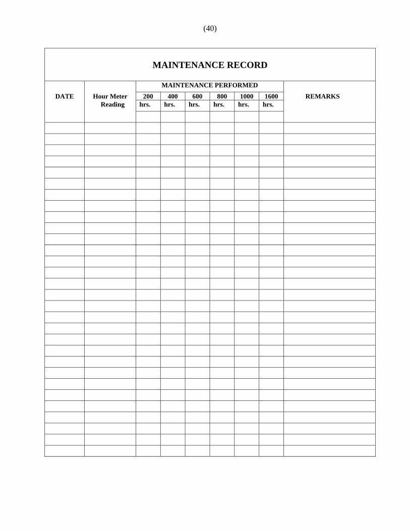
MAINTENANCE RECORD
MAINTENANCE PERFORMED
DATE Hour Meter 200 400 600 800 1000 1600 REMARKS Reading hrs. hrs. hrs. hrs. hrs. hrs.