Report of the Committee on Alternative Pmtocfion Options to I-Ialon . iNenno, Cha/r Assoc. Inc., MD ~rin L Harrington, Secraa~ gton Group, Inc., GA William M. Care),, Underwriters Laboratories Inc., IL Jon S. Casler, Eke Protection Systems, MO Salvatore A. Chines, Industrial Risk Insurers, CT Pep. Industrial Risk Insurers Logim T. ][tidier, Ansul Fh'e Protection, FL Rep. Halon Alternative Research Corp. John Foreacre, St. Paul Companies, IL Wi~iam J. Fries, Liberty Mutual Insurance CO., MA Rep. The Alliance of American Insurers M anjeri IL Go.palan, MCI Telecom'munications Corp., TX Ello G "elml, North American Fire Guardian Tech Inc. Canada . . . • • Alaalmr Gupta, Boeing Commercial AirplaneGroup,WA David H. I~y, U.S. Dept. of the Navy, I)C George A, Krabhe, Automatic Suppression Systems Inc., IL Rep. Fire Suppression Systems Assn. James D. Lake, Nat'l Fire Sprinkler Assn., NY Micheile Maynard, Nat'l Aeronautics 8* Space Admin., FL Robert C. Merritt, Factory Mutual Research Corp., MA Daniel W. Moore, The DuPont Company. DE lm A. Pigaato, Jr., 3M CO., MN • Douglas Register, Great Lakes Chemical Corp., IN Wiillam J. ~eld, Hartford Steam Boiler Inspection -& Insurance Co., CT Jeseph A. Seeecal, Fenwal Safety Systems, MA Clifford IL Sinopoli, Baltimore Gas & Electric, MD Pep. Electric Light Power Group/Edison Electric Inst. Louise C. Spelte~, Federal Aviation Administration, NJ Steven W. Stone, CIGNA Loss Control Services Inc.,TX Pep. American Insurance Services Group, Inc. Robert E. Tapscott, New Mexico Engr Research Inst., NM Tim N. Testerman, Procter & Gamble, OH Stephen B. Watovs, Fireline Corp., MD Rep. Nat'l Assn. of Fire Equipment Distributors Inc. Robert T. Wicidtam, Kidde-Fenwal, Inc., MA Rep. Nat'l Electrical Mfrs Assn. Alternates Kerry M. Bell, Underwriters Laboratories Inc., IL (&It. to W. M. Carey) Robert L Darwin, U.S. Dept. of the Navy, DC (Alt. to D. H. Kay) William A. Froh, U.S. Dept. of Energy, DC (Vot Ah. for DOE Rep.) Oarlstopher P. I-Ianauslm, Hughes Assoc., Inc., MN (Alt. to P.J. DiNenno) James P. H-ehert, Universal Fire Equipment Co., TX (&It. to S. B. Waters) Jeffrey F. Moore, Fike Protection Systems, MO (&It. toJ. S. Casler) Michad J. Prowse, Cerberus Pyrotronics, NJ (&it. to 1Z T. Wickham) Paul E. Rivem, 3M Co.. MN (Alt. toJ. A. Piguato) Todd E. Schumann, Industrial Risk Insurers, IL (Alt. to S. Chines) Stephanie R. Skaggs, New Mexico Engr Research Inst. (Alt. to 1~ E. Tapscott) David C. Sm/th, Factory Mutual Research Corp., MA (&It. to R. C. Merritt) Al Thornton, Great Lakes Chemical Corp. TX (Alt. to W. D. Register) Charles F. Wilhns, Fire Suppression Systems Assoc., NC (Ah. to G. A. Krabbe) Jmeph A. Wright,FederalAviation Administration Tech Ctr., NJ (Ah. to L C.Speltel) Nonvoeng Anatoly Baratov, C~vil Engr University, Russia Michael John Holmes, Preussag Fire Protection Ltd., England Brian J. Meacham, FireTech, Switzerland Dougtas J, Pickemgill, Fire and Safety Systems, Australia Fernando Vigara, Vimpex - Security Devises, SA, Spain Staff Liaison: CaseyC. Grant This list ~ the monbership at the time the Committee wa~ balloted on the text of this edition. Since that time, changes in the membership may have occurred. Committee Scope: This Committee shall have primary responsibility for documents on alternative protection options to Halon 1501 and 1211 fire extinguishing systems, It shall not deal with design, installation, o0eration testing, and maintenance of systems employing carbon dioxide, dry" chemical, wet chemical, foam, Halon 1501, Halon 2211, Halon 2402, or water as the primary extinguishing media. This Committee shall also have the respgnsibility of developing documents for comparing the properties of suppression systems relative to the occupan- des beifig prdtected. - . . . . The Report of the Technical Committee on Alternative Protection Options to Halon is presented for adoption. This Report was prepared by the Tedmical Committee on Altesnative Prote~on Options to I-Ialon and proposes for adoption amendments to NFPA 2001-1994, Standard on Clean Agent Fire _ _F_,~inguis" "h~g system. NFPA 2001- 1994 ispublished in Volume 9 of the 1994 National Fife Codes and in separate pamphlet form. This Report has been submitted to letter ballot of the Technical Committee on Alternative Protection Options to Halon which consists of 29 voting members; of whom 26 affirmatively, 1 negatively (Mr. Wickham), and2 ballots were not returned (Messrs. Cosier and Moore). Mr. Wickham vote negatively stating: :There are several proposals - most notably (but not limited to) Logs #56, 57, 59, 60 and 61, that contain technical data without any form of techntcal substantiation. It is inappropriate to incorporate this type of information in the standard without the-benefit of a review- by members of the technical committee - of laboratory reports (for measured data) and derivations (for formulae). In the absence of this information, the National Electrical Manufacturers Association has directed a negative ballot on F95-ROP for NTPA 2001, Standard on Clean Agent Fire Extinguishing System&" Mr. Chines voted affirmatively with the following comments: "I have voted affirmatively becatise I believe the standard's revision process should go forward. However• I would like to comment on my concerns and need for editorial changes byLog numbers: Log#4 (Table 1-4.2.2), Log #15 (Table 1-4.2.2) and Log #CP1 (1-5.2). In Las Vegas, Dr. Lambertson made a very convincing case for allowing lower than normal oxygen levels in the presence of CO 2. -He indicated he was misquoted by his detractors. As a result IG-542 was found to be acceptable for inclusion and suitable in occupied areas. Inert gas agents that do not contain CO 2 should not be allowed to drop oxygen levels as low as IG-541. Log #64 (2-1.2). The third sentence of the proposal provides needed quality control. Revise his existing text to read ~eacfi system container." Log#6 (2-1.4.2). Is it possible to standardize IG pressure? When IG 541 was accepted there was much concern over piping safety, pressure reducer safety and bperation, and noise levels. Log #5t, (2-1.4.5 and A-2-1.4.5). Will CO 2 in IG-541 become 2 phase at lower discharge pressures. Log #1"9 (2-2.1.1(e)) and Log#57 (2-2.1(0). Section should address the need for fail-safe pressure regulation. The use of orifice plates reduces moving parts. Log#8~2-2.5.5). Suggest "Nozzles shall be designed to minimize unhealthy noise levels." Log #39 (Table 3-5.1 (a)). Where is °C data for IG-55? Log#40 (Table 5-5.1(k)). Why is this data on basis of weight per unit volume? IG a~ent data should be as consistent as possible. LOg #37 DratYtneeds p_magraph bar line to show ft has been revised. Log #13 (4-7.2.2.12). If you decrease the test pressure you should also decrease the percent of allowable leakage. At such low pressures allowable leakage should be negligible. Log #2 (Table A-14.1(a)), Log #24 (Table A-14.1(a)), and Log #41 (Table A- 14.1]a)). Data for IG-55 and IC,-01 are not complete. SI data is needed and should be added. Log#29 (A-2-2.1.1) and Log #45 (A-2-2.1.1). Why are IG agent pressures different than Table 2-1.4.1. Log #30 (A-2-2.5.1 (e)). Should u'y to standardize text for IG systems. Log #60 (Table A-3-4.2.1) and Log #61 (Table A-3.4.2.2). Data prepared by GLCC should be put into a single expanded table with similar data from other manufacturer's. Log#1 (A-5-4.3). Committee voted to change formula, yet it has not been changed in the committee action or on the final draft. It alSpears from various tests that generally shorter discharge times and ag Where is generic informatmn for engineered systems promised in this second edition? ~ Mr. Gupta voted affirmatively with the following comments: 1. Paragraph 1-3 Defintions and Units, suggest add: Sea Level Equivalent. Having a properW that is equivalent to that which exists at barometric pressure of 760 mmHg. At sea-level, agas mixture containing 16 percent o~gen exerts a partial pressure of 12"1.6 mm Hg. The oxygen partial pressure with 12 percent oxygen is 91.2 mm Hg. 2. Table 1-4.2.2 Note 2: - - The note identifies the percentage compositions of IG-541 and HCacC Blend A by volume and weight respectively. It does not address IG-01 and IG-55. I think these should also be addressed. Suggest change first stance of the note to read: "Ctmposition of IG-01, IG-541 and IG-55 are given in percent by volume." 3. SuFd~est add: 1-5.1.2.'2............... used in a normally occupied area at sea-level. 1.5.2.3 occupied areas at sea level. 4. Table 2-2.2(b) suggest delete in column under IG-541-0.0%. 5. Table 2-1.4.1 Correct Last line 1 lb/ft$ = 16.0183 kg/m3 6. Table 5-5.20) IG-01 Total flooding Quantity Correct Note 2 V/V {Agent Volume ............ } 7. Table $-5.1(k) I suggest that the manufacturer be required to provide the data in terms of V/V. I am afraid that we have two types of tables for inert gas agents: V/V for IG-0I and IG-541, and W/V for IG-55. This can lead to mtstakes. We should try to be consistent. 8. Table $-6 Suggest correct. It has several errors: Altitude 5000 ft (1.52 kin) 6000 ft (1.83 kin) 7000 ft (2.13 kin) 8000 ft (2.44 kin) 9000 ft (2.74 kin) 9. Table A-I-5.1.3 change to read: 12 percent sea-level eqmvalent . ......... I0 percent sea-level equivalent.......... 128
Transcript
Report of the Committee on
Alternative Pmtocfion Options to I-Ialon
. iNenno, Cha/r Assoc. Inc., MD
~rin L Harrington, Secraa~ gton Group, Inc., GA
William M. Care),, Underwriters Laboratories Inc., IL Jon S. Casler, Eke Protection Systems, MO Salvatore A. Chines, Industrial Risk Insurers, CT
Rep. Halon Alternative Research Corp. John Foreacre, St. Paul Companies, IL Wi~iam J. Fries, Liberty Mutual Insurance CO., MA
Rep. The Alliance of American Insurers M anjeri IL Go.palan, MCI Telecom'munications Corp., TX Ello G "elml, North American Fire Guardian Tech Inc. Canada
. . . • •
Alaalmr Gupta, Boeing Commercial Airplane Group, WA David H. I~y, U.S. Dept. of the Navy, I)C George A, Krabhe, Automatic Suppression Systems Inc., IL
Rep. Fire Suppression Systems Assn. James D. Lake, Nat'l Fire Sprinkler Assn., NY Micheile Maynard, Nat'l Aeronautics 8* Space Admin., FL Robert C. Merritt, Factory Mutual Research Corp., MA Daniel W. Moore, The DuPont Company. DE
lm A. Pigaato, Jr., 3M CO., MN • Douglas Register, Great Lakes Chemical Corp., IN
Wiillam J. ~ e l d , Hartford Steam Boiler Inspection -& Insurance Co., CT Jeseph A. Seeecal, Fenwal Safety Systems, MA Clifford IL Sinopoli, Baltimore Gas & Electric, MD
Pep. Electric Light Power Group/Edison Electric Inst. Louise C. Spelte~, Federal Aviation Administration, N J Steven W. Stone, CIGNA Loss Control Services Inc.,TX
Pep. American Insurance Services Group, Inc. Robert E. Tapscott, New Mexico Engr Research Inst., NM Tim N. Testerman, Procter & Gamble, OH Stephen B. Watovs, Fireline Corp., MD
Rep. Nat'l Assn. of Fire Equipment Distributors Inc. Robert T. Wicidtam, Kidde-Fenwal, Inc., MA
Rep. Nat'l Electrical Mfrs Assn.
Alternates
Kerry M. Bell, Underwriters Laboratories Inc., IL (&It. to W. M. Carey)
Robert L Darwin, U.S. Dept. of the Navy, DC (Alt. to D. H. Kay)
William A. Froh, U.S. Dept. of Energy, DC (Vot Ah. for DOE Rep.)
Oarlstopher P. I-Ianauslm, Hughes Assoc., Inc., MN (Alt. to P.J. DiNenno)
James P. H-ehert, Universal Fire Equipment Co., TX (&It. to S. B. Waters)
Jeffrey F. Moore, Fike Protection Systems, MO (&It. toJ. S. Casler)
Michad J. Prowse, Cerberus Pyrotronics, NJ (&it. to 1Z T. Wickham)
Paul E. Rivem, 3M Co.. MN (Alt. toJ. A. Piguato)
Todd E. Schumann, Industrial Risk Insurers, IL (Alt. to S. Chines)
Stephanie R. Skaggs, New Mexico Engr Research Inst. (Alt. to 1~ E. Tapscott)
David C. Sm/th, Factory Mutual Research Corp., MA (&It. to R. C. Merritt)
Al Thornton, Great Lakes Chemical Corp. TX (Alt. to W. D. Register)
Charles F. Wilhns, Fire Suppression Systems Assoc., NC (Ah. to G. A. Krabbe)
Jmeph A. Wright, Federal Aviation Administration Tech Ctr., NJ (Ah. to L C.Speltel)
Nonvoeng Anatoly Baratov, C~vil Engr University, Russia Michael John Holmes, Preussag Fire Protection Ltd., England Brian J. Meacham, FireTech, Switzerland Dougtas J, Pickemgill, Fire and Safety Systems, Australia Fernando Vigara, Vimpex - Security Devises, SA, Spain
Staff Liaison: CaseyC. Grant
This list ~ the monbership at the time the Committee wa~ balloted on the text of this edition. Since that time, changes in the membership may have occurred.
Committee Scope: This Committee shall have primary responsibility for documents on alternative protection options to Halon 1501 and 1211 fire extinguishing systems, It shall not deal with design, installation, o0eration testing, and maintenance of systems employing carbon dioxide, dry" chemical, wet chemical, foam, Halon 1501, Halon 2211, Halon 2402, or water as the primary extinguishing media.
This Committee shall also have the respgnsibility of developing documents for comparing the properties of suppression systems relative to the occupan- des beifig prdtected. - . . . .
The Report of the Technical Committee on Alternative Protection Options to Halon is presented for adoption.
This Report was prepared by the Tedmical Committee on Altesnative P r o t e ~ o n Options to I-Ialon and proposes for adoption amendments to NFPA 2001-1994, Standard on Clean Agent Fire _ _F_,~inguis" "h~g system. NFPA 2001- 1994 ispublished in Volume 9 of the 1994 National Fife Codes and in separate pamphlet form.
This Report has been submitted to letter ballot of the Technical Committee on Alternative Protection Options to Halon which consists of 29 voting members; of whom 26 affirmatively, 1 negatively (Mr. Wickham), a n d 2 ballots were not returned (Messrs. Cosier and Moore).
Mr. Wickham vote negatively stating: : T h e r e are several proposals - most notably (but not limited to) Logs #56, 57, 59, 60 and 61, that contain technical data without any form of techntcal substantiation. It is inappropriate to incorporate this type of information in the standard without the-benefit of a review- by members of the technical committee - of laboratory reports (for measured data) and derivations (for formulae). In the absence of this information, the National Electrical Manufacturers Association has directed a negative ballot on F95-ROP for NTPA 2001, Standard on Clean Agent Fire Extinguishing System&"
Mr. Chines voted affirmatively with the following comments: "I have voted affirmatively becatise I believe the standard's revision process
should go forward. However• I would like to comment on my concerns and need for editorial changes byLog numbers:
Log#4 (Table 1-4.2.2), Log #15 (Table 1-4.2.2) and Log #CP1 (1-5.2). In Las Vegas, Dr. Lambertson made a very convincing case for allowing lower than normal oxygen levels in the presence of CO 2. -He indicated he was misquoted by his detractors. As a result IG-542 was found to be acceptable for inclusion and suitable in occupied areas. Inert gas agents that do not contain CO 2 should not be allowed to drop oxygen levels as low as IG-541.
Log #64 (2-1.2). The third sentence of the proposal provides needed quality control. Revise his existing text to read ~eacfi system container."
Log#6 (2-1.4.2). Is it possible to standardize IG pressure? When IG 541 was accepted there was much concern over piping safety, pressure reducer safety and bperation, and noise levels.
Log #5t, (2-1.4.5 and A-2-1.4.5). Will CO 2 in IG-541 become 2 phase at lower discharge pressures.
Log #1"9 (2-2.1.1(e)) and Log#57 (2-2.1(0). Section should address the need for fail-safe pressure regulation. The use of orifice plates reduces moving parts.
Log#8~2-2.5.5). Suggest "Nozzles shall be designed to minimize unhealthy noise levels."
Log #39 (Table 3-5.1 (a)). Where is °C data for IG-55? Log#40 (Table 5-5.1(k)). Why is this data on basis of weight per unit
volume? IG a~ent data should be as consistent as possible. LOg #37 DratYt needs p_magraph bar line to show ft has been revised. Log #13 (4-7.2.2.12). If you decrease the test pressure you should also
decrease the percent of allowable leakage. At such low pressures allowable leakage should be negligible.
Log #2 (Table A-14.1(a)), Log #24 (Table A-14.1(a)), and Log #41 (Table A- 14.1]a)). Data for IG-55 and IC,-01 are not complete. SI data is needed and should be added.
Log#29 (A-2-2.1.1) and Log #45 (A-2-2.1.1). Why are IG agent pressures different than Table 2-1.4.1.
Log #30 (A-2-2.5.1 (e)). Should u'y to standardize text for IG systems. Log #60 (Table A-3-4.2.1) and Log #61 (Table A-3.4.2.2). Data prepared by
GLCC should be put into a single expanded table with similar data from other manufacturer's.
Log#1 (A-5-4.3). Committee voted to change formula, yet it has not been changed in the committee action or on the final draft.
It alSpears from various tests that generally shorter discharge times and
ag Where is generic informatmn for engineered systems promised in this second
edition? ~ Mr. Gupta voted affirmatively with the following comments: 1. Paragraph 1-3 Defintions and Units, suggest add: Sea Level Equivalent. Having a properW that is equivalent to that which
exists at barometric pressure of 760 m m H g . At sea-level, agas mixture containing 16 percent o ~ g e n exerts a partial pressure of 12"1.6 mm Hg. The oxygen partial pressure with 12 percent oxygen is 91.2 mm Hg.
2. Table 1-4.2.2 Note 2: - - The note identifies the percentage compositions of IG-541 and HCacC Blend
A by volume and weight respectively. I t does not address IG-01 and IG-55. I think these should also be addressed.
Suggest change first stance of the note to read: "Ctmposition of IG-01, IG-541 and IG-55 are given in percent by volume." 3. SuFd~est add: 1-5.1.2.'2 ............... used in a normally occupied area at sea-level. 1.5.2.3 occupied areas at sea level. 4. Table 2-2.2(b) suggest delete in column under IG-541-0.0%. 5. Table 2-1.4.1 Correct Last line 1 lb/ft$ = 16.0183 kg/m3 6. Table 5-5.20) IG-01 Total flooding Quantity Correct Note 2 V/V {Agent Volume ............ } 7. Table $-5.1(k) I suggest that the manufacturer be required to provide the
data in terms of V/V. I am afraid that we have two types of tables for inert gas agents: V/V for IG-0I and IG-541, and W/V for IG-55. This can lead to mtstakes. We should try to be consistent.
8. Table $-6 Suggest correct. It has several errors: Altitude
5000 ft (1.52 kin) 6000 ft (1.83 kin) 7000 ft (2.13 kin) 8000 ft (2.44 kin) 9000 ft (2.74 kin)
( Log #12) 2001- 1 - (1-3.1 Glean Agent): Reject SUBMITIXR: EricJ. Zinn, Spectrex, Inc. RECOMMENDATION: The definition of Clean Agent needs to be addressed because the SFE aerosol leaves a small amount of residue, however, the amount of residue is so small it is considered by many to be insignificant and the residue appears to be benign. Even though an agent leaves a residue, it can still be considered a clean
ANTIATION: In accordance with the procedures estab- lished by the NFPA Codes and Standards Development Process, Spectrex, Inc. a developer and manufacturer of an alternative total flooding fire extinguishing agent to halon called Spectrex Fire Extinguishant (SPE) or Encapsulated micron Aerosol Agent (EMAA), respectfully request that the Technical Committee on Alternative Protection Options to Halon consider adding SPE to the NFPA 2001 Standard.
SPE is a new technology that produces an aerosol consisting of both gases and micron size solid particulates generated through an oxidation-reduction process, therefore, SFE does not meet some of the criterion of the new NFPA 2001 Standard.
Paragraph 1-2.1 states "Nothing in this standard is in tended to restrict new technology or alternative arrangements provided the restrict new technology or alternative arrangements provided the level of safety prescribed by this standard is no t lowered." Paragraph 1-2.2 goes on to state "No standard can be promulgated that will provide all the necessary criteria for the implementat ion of a total flooding, clean agent fire extinguishing system. Technology in this area is under constant development, and this will be reflected in revisions to this standard."
Based on the paragraphs quoted above, it is obvious that the Technical Committee on Alternative Protection Options to Halon recognize that technologiessuch as SFE would be for thcoming and they were wise enough to design the standard as a "living docu- ment." In concert with their intent, we submit these r ecommended changes to the NFPA 2001 Standard. COMMITrEE ACTION: Reject. COMMITrEE STATEMENT: This technology is outside the scope of NFPA 2001. The definition of clean agent should not be changed because it is appropriate and is consistent with the intent of the document . The technology is substantially different from the agents presendy included in NFPA 2001 and is more appropriate in a separate document .
(Log #50) 2001- 2 - (1-3.1 Inert Gas Agent): Accept SUBMITTER: Logan T. Fidler, Ansul Fire Protection RECOMMENDATION: Revise Inert Gas Agent definition to:
Inert Gas Agent. A clean agent that contains as primary compo- nents one or more of the gases lielium, neon, argon, or nitrogen. Iner tgas agents that are blends of gases may also contain carbon dioxide as a secondary component . SUBSTANTIATION: Avoids potential conflict with Carbon Dioxide Standard. COMMITTEE ACTION: Accept.
(Log #62) 2001- 3 - (1-3.1 Inert Gas Agent): Accept in Principle SUBMITrER: Robert Langer, Ansul Fire Protection RECOMMENDATION: Revise text as follows:
Inert Gas Agent. A clean agent that contains one or more of the gases helium, neon, argon, or nitrogen. Blends of Inert Gas Agents
SO contain carbon dioxide. ANTIATION: Avoids potential conflict with Carbon Dioxide
Standard NFPA 12. Removing "Primary" to avoid inclusion of non- inert gases or other material in blends. Current definition has no control over potential material contained in an inert gas blend. COMMITrEEACTION: Accept in Principle. CoMMrlTEE STATEMENT: Refer to the Action on Proposal 2001-2 (Log #50).
(Log #4) 2001-4- (Table 1-4.1.2): Accept Note: This proposal appea redas comment 2001-23 which was held
for fur ther study from the Fall 93 TCD, which was on proposal 2001-1. SUBMITTER: Michel N. Charette, Securiplex Technologies Inc. RECOMMENDATION: Add clean agent IG-55 (Argonite) as follows:
IG-55 Nitrogen (50%) N2, AR Argon (50%)
SUBSTANTIATION: Argonite does not use CO2 in the gas mixture because of health hazard associated with it's usage and also because of our disagreement with claimed benefits of having CO2 in the mixture to help oxygen intake in case of exposure to the gas.
NOTE: Support ing material is available for review at NFPA Headquarters. COMMYITEE ACTION: Accept.
(Log #15) 2001- 5 - (Table 1-4.1.2): Accept in Principle $UBMITTER: Hartmut E. Donner , Minimax GmbH RECOMMENDATION: Add new text as follows:
"IG-100 Argon (99.9%) AR" SUBSTANTIATION: Proposal to add IG-100 to NFPA 2001.
This clean agent has been used successfully for fire protection. NOTE: Supporting material is available for review at NFPA
headquarters. COMMITrEE ACTION: Accept in Principle. Accept the submitters recommendat ion, except change the
designation to "IG-01" COMMITTEE STATEMENT: This meets the intent of the submitter, but revises the designation in accordance with the format used by, NFPA 2001.
(Log #34) 2001- 6 - (Table 1-4.1.2): Accept SUBMITTER= Ole Bjarnsholt, Ginge-Kerr RECOMMENDATION: Add to Table 1-4.1.2:
IG 55 Nitrogen (50%) N 2 Argon (50%) Ar
SUBSTANTIATION: We propose to add Glean Agent IG 55 as follows:
Proposal for revision is submitted in order to include a new agent IG-55 in the 2001 standard. COMMITrEE ACTION: Accept.
(Log #CP1) 2001- 7- (1-5.1): Accept SUBMITrER: Technical Co~nmittee on Alternative Protection l ~ t i o n s to Halon
COMMENDATION: 1. Revise section 1-5.1 as follows: 1-5.1" Hazards to Personnel. 1-5.1.1" Any agent that is to be recognized by NFPA 2001 as
acceptable for use in normally occupied spaces shall first be evaluated in a manner equivalent to the process used b~, the U.S. Environmental Protection Agency's SNAP Program.
NOTE: The U.S. Environmental Protection Agency's SNAP Program was originally outl ined in Federal Register 59 FR 13044.
1-5.1.2" Halocarbon Clean Agents. 1-5.1.2.1 Unnecessary exposure to all halocarbon clean agents and
their decomposit ion products shall be avoided. Haiocarbon agents for which the design concentrat ion is equal to or less than the NOAEL shall be permit ted for use in normally occupied areas. Halocarbon agents for which the design concentrat ion is greater than the NOAEL shall not be permit ted for use in normally occupied areas.
1-5.1.2.2 To keep oxygen concentrations above 16 percent (sea level equivalent), the point at which onset of impaired personnel function occurs, no halocarbon fire extinguishing agents addressed in this standard shall be used in a normally occupied area of concentrat ion greater than 24 percgnt.
129
N F P A 2001 - - F95 R O P
1-5.1.3" Inert Gas Clean Agents. No inert gas agent with a design concentrat ion above 43 percent , which corresponds to an oxygen concentration of 12 percent (sea level equivalent), shall be permit ted for use in normally occupied areas.
1-5.1.4" Safety Requirements. For fire situations, suitable safeguards shall be provided to ensure p rompt evacuation of and prevent entry into hazardous atmospheres and also to provide means for p rompt rescue of any t rapped personnel. Safety items such as
~ ersonnel training, warning signs, discharge alarms, self-contained reathing apparatus, evacuation plans, and fire drills shall be
considered. 2. Revise the heading for A-1-5.1.2 to A-1-5.1.4. 3. Revise section A-1-5.1.1 and related sections as follows: A-1-5.1 Potential hazards to be considered for individual systems
are the following: (a) Noise. Discharge of a system can cause noise loud enough to
be startling but ordinarily insufficient to cause traumatic injury. (b) Turbulence. High velocity discharge from nozzles may be
sufficient to dislodge substantial objects directly in the path. System discharge may cause enough general turbulence in the enclosures to move unsecured paper and light objects.
(c) Cold Temperature. Direct contact with the vaporizing liquid being discharged f rom a system will have a strong chilling effect on objects and can cause frostbite burns to the skin. The liquid phase vaporizes rapidly when mixed with air and thus limits the hazard to the immediate vicinity of the discharge point. In humid atmo-
minor reduct ion in visibility may occur for a brief per iod e to the condensat ion of water vapor.
A-I-5.1.1 The discharge of clean agent systems to extinguish a fire may create a hazard to personnel from the natural form of the dean agent or f rom the products of decomposi t ion that result f rom exposure of the agent to the fire or hot surfaces. Unnecessary exposure of personnel to either the natural agent or to the decomposi t ion products should be avoided.
A-1-5.1.2 Halocarbon Clean Agents. Table A-1-5.1.2 provides • information on toxicological and physiological effects of halocarbon
agents covered by this standard. The No Observed Adverse Effect Level (NOAEL) is the highest concentrat ion at which no adverse physiological or toxicological effect has been observed. The Lowest Observed Adverse Effect Level (LOAEL) is the lowest concentrat ion at which an adverse physiological or toxicologik:al effect has been observed.
Restrictions on the use of certain halocarbon agents covered in this standard for use in normally occupied areas are based on a comparison of the actual agent concentrat ion to the NOAEL. Where the actual concentrat ion will be higher than the NOAEL or where the needed data are unavailable, the agents are restricted to use only in areas that are no t normally occupied. To keep oxygen concentra- tions above 16 percen t (sea level equivalent), the point at which onset of impaired personnel function occurs, no halogenated fire extinguishing agents addressed in this standard should be used in a normally occupied area of concentrat ion greater than 24 percent. Although most o f the clean agents have a low level of toxicity, the
decomposi t ion products generated by the clean agent breaking down in the presence of very high amounts of heat may be hazard- ous. All of the present halocarbon agents contain fluorine. In the presence of available hydrogen (from water vapor, or the combus- tion process itself) the main decomposi t ion product is hydrogen fluoride (HF).
These decomposi t ion products have a sharp, acrid odor, even in minute concentrat ions of only a few parts per million. This characteristic provides a built-in warning system for the agent, but at the same time creates a noxious, irritating a tmosphere for those who must enter the hazard following a fire. The amount of agent that can be expected to decompose in
extinguishing a fire depends to a large extent on the size of the fire, the particular clean agent, the concentrat ion of the agent, and the length of timb the agent is in contact with the flame or heated surfac e. If there is avery rapid buildup of concenllat ioo to the critical value, then the fire will be extinl~uished quickly and the decomposing will b e limited to the m i m m u m possible with that agent. Should that agent 's specific composition be such that it could generat e large quantities of decomposi t ion products, and the time to achieve the critical value is lengthy, then the quantity of decompo- sition products may be quite great. The actual concentrat ion of the decomposi t ion products must then depend on the volume of the room in which the fire was burn ing and on the degree of mixing and ventilation.
Clearly, longer exposure of the agent to high temperatures would produce greater concentrat ions of these gases. The type and sensitivity of detection, coupled with the rate of discharge, should be selected to minimize the exposure time of the agent to the elevated temperature ff the concentrat ion of the breakdown products must
be minimized. In most cases the area would be untenable for human occupancy due to the heat and breakdown products of the fire itself. A-1-5.1.3 Inert Gas Clean Agents. Table A-1-5.1.3 provides
information on physiological effects of inert gas agents covered by this standard. The health concern for inert gas clean agents is asphyxiation due to the lowered oxygen levels. With inert gas agents, an oxygen concentrat ion of no less than 12 percent (sea level equivalent) is required for normally occupied areas. This corre- sponds to an agent concentrat ion of no more than 43 percent.
IG-541 uses carbon dioxide to promote breathing characteristics in tended to sustain life in the oxygen deficient environment for protection of personnel. Care should be used not to design inert gas-type systems for normally occupied areas using design concentra- tions higher than that specified in the system manufacturer 's listed design manual for the hazard being protected.
Inert gas clean agents do no t decompose measurably in extinguish- ing a fire. As such, toxic or corrosive decomposi t ion products are not found. However, heat and breakdown products of the fire itself can still be substantial and could make the area untenable for human occupancy.
4. Revise the Table A-I-5.1.1 to Table A-1-5.1.2 with a title of "Toxidty Information for Halocarbon Clean Agents". Also delete the row for IG-541 and delete the note information designated by the asterisk as follows:
Table A-1-5.1.2 Toxicity Information for Halocarbon Clean Agents
NOTE 1: LCs0 is the concentration lethal to 50% of a rat population during a 4-hour exposure. The ALC is the approximate lethal concentration.
NOTE 2: The cardiac sensitization levels are based on the observance or non-observance of serious heart arrhythmias in a dog. The usual protocol is a 5-minute exposure followed by a challenge with epinephrine.
NOTE 3: High concentration values are determined with the addition of oxygen to prevent asphyxiation.
NOTE 4: Values for Halon 1301 are included in this table for sake of comparison.
5. Insert a new Table A-1-5.1.3 entitled "Physiological Effects for Inert Gas Agents" as follows:
Table A-1-5.1.3 Physiological Effects for Inert Gas Agents
6 g e m ~ IG-01 43% 52% IG-55 43% 52% IG-541 43% 52%
* Based on physiological effects in humans in hypoxic atmospheres. These values are the functional equivalents o f NOAEL and LOAEL values, and correspond to 12 percent min imum oxygen for the N o Effect Level and I0 percent min imum oxygen for the Low Effect Level. SUBSTANTIATION: This separates halocarbon clean agents from inert gas clean agents to accommodate the fundamental differences in physiological effects between the various agents. With regard to the changes to the value in the old Table A-1-5.1.1, refer to the Action on Proposal 2001-53 (Log #CP3). COMMYITEE ACTION: Accept.
130
N F P A 2001 - - F95 R O P
(Log #66) 2001- 8- (2-1): Reject SUBMITTER: EricJ. Zinn, Spectrex, Inc. RECOMMENDATION: Components and 2-2 - Distribution may need to be addressed since SFE will not use super pressurized vessels and other equipment normally associated with pressurized gaseous YSui~tems-
TANTIATION: Refer to substantiation for Proposal 2001-1
(C~gM~FEE ACTION: Reject. COMMrITEE STATEMENT: Refer to the Action on Proposal 2001-1 (Log #12).
(Log #16) 2001- 9 - (2-1.2): Accept in Principle SUBMITrER: Hartmut E. Donner, Minimax GmbH RECOMMENDATION: Revise first sentence:
"New clean agents shall comply with the standard of quality as shown in Tables 2-1.2(a), 2-1.2(b), 2-1.2(c) and 2-1.2(d)." SUBSTANTIATION: Data of the new agent IG-100 are given in Table 2-1.2(d).
Refer to Substantiation for Proposal 2001-5 (Log #15). COMMITTEE ACTION: Accept in Principle. COMMITTEE STATEMENT: Refer to the Action on Proposal 2001-13 (Log #17).
Add the values recommended by the submitter to Table 2-1.2(b). Also remove the percent sign following the submitters value for water content. COMMITrEE STATEMENT: Editorial.
(Log #5) 2001- 12 - (Table 2-1.2(b)): Accept in Principle Note: This proposal appeared as comment 2001-62 which was held
for further study from the Fall 93 TGD, which was on proposal 2001-23. SUBMITrER: Michel N. Charette, Securiplex Technologies Inc. RECOMMENDATION: Add IG-55 gas to the inert gas agent quality requirements:
Composition IG-55 N2 - 50% + 5% Ar - 50% +5%
Water content by 0.50 sWu~hANt, maximum
TIATION: None. COMMITrEE ACTION: Accept in Principle. COMMITrEE STATEMENT: Refer to Action on Proposal 2001-11 (Log #35).
(Log #64) 2001- 10 - (2-1.2): Accept in Prindple SUBMrrTER: Douglas Register, Great Lakes Chemical Corporation RECOMMENDATION: Add the following to the end of sentence tWO:
"Clean agent blends must remain homogeneous in storage and use under the anticipated temperature range and conditions of service that they will encounter. These agent blends shall not be rendered inhomogeneous as a result of service conditions. Blend quality requirements must be separately evaluated for each system cylinder to assure conformance to the agent's quality requirements as stated in Section 2-1.2." SUBSTANTIATION: Problems with stratification of some blend agents upon storage have'been reported. In one case, after removing most of the agent from a cylinder, a flammable liquid residue was noted. This presents the possibility that filling a system from a stratified bulk tank or cylinder could result in an agent that does not conform to NFPA 2001 quality guidelines and could possibly present additional hazard to the occupants. COMMITTEE ACTION: Accept in Principle. Add the following to the end of sentence two: "Clean agent blends shall remain homogeneous in storage and use
under the listed temperature range and conditions of service that they will encounter.-- COMMITrEE STATEMENT: The submitter's second sentence is redundant with the first, and the third sentence puts forth impracti- cal and excessive criteria. Other changes to the first sentence are editorial.
(Log #35) 2001- 11 - (2-1.2 and Table 2-1.2(e) (New)): Accept in Principle SUBMITI'ER: Ole Bjarnsholt, Ginge-Kerr RECOMMENDATION: 1. Change first sentence:
"New clean agents shall comply with the standard of quality as shown in Tables 2-1.2(a), 2-1.2(c), 2-1.2(d) and 2-1.2(e)."
2. Add newTable 2-1.2.(e):
Table 2-1.2(e) Inert Gas CaeanAgent Quality Requirements
IG 55
Composition, % by volume
Water Content, % by Weight
N 2 50% + 5% Ar 50% + 5%
Maximum 0.005%
SUI~TANTIATION: Proposal for revision is submitted in order to include a new agent IG-55 in the 2001 standard. COMMITTEE ACTION: Accept in Principle.
2001- 13 - (Table 2-1.2(d) (New)): Accept in Principle SUBMITTER: Hartmut E. Donner, Minimax GmbH RECOMMENDATION: Add a new Table:
Table 2-1.2(d) Inert Gas Clean Agent Quality Requirements
(Log#17)
IG-100
Water Content, % by Weight Ar 99.9% Maximum 0.005%
SUBSTANTIATION: Proposal to add IG-100 to NFPA 2001. This clean agent has been used successfully for fire protection. Refer to Substantiation for Proposal 2001-5 (Log #15).
COMMITrEEACTION: Accept in Principle. Add the values recommended by the submitter to Table 2-1.2(b).
Also remove the percent sign following the submitters value for water content and revise IG-100 to IG-01. COMMITTEE STATEMENT: Editorial. Refer to the Action on Proposal 2001-5 (Log#lS).
(Log #6) 2001- 14- (2-1.4.1): Accept in Principle Note: This proposal appeared as comment 2001-70 which was held
for further study from the Fall 93 TCD, which was on proposal 2001-23. SUBMITrER: Michel N. Charette, Securiplex Technol~ies Inc. RECOMMF_2qDATION: Add the following words (underline) in the Note:
"The maximum fill densityxequirements is not applicable of IG-541 and I~55. The maximum container pressure for IG-541 is 2175 psig at 70°F and is 4350 nsi~ at 70°F for IG-55." SU1K~TANTIATION: ~ecuriplex Argonite systems are using a higher pressure (300 bar). Proposed note would restrict the use of containers with higher pressurization than used for the IG-541 for no reason. C O M M I T r ~ ACTION: Accept in Principle. COMMITTEE STATEMENT: Refer to Action on Proposal 2001-16 (Log #36).
(Log #l 8) 2001- 15 - (Table 2-1.4.1): Accept in Principle SUBMITTER: Hartmut E. Donner, Minimax GmbH
I RECOMMENDATION: Add a new column to Table 2-1.4.1 Storage Container Characteristics.
131
N F P A 2001 m F 9 5 R O P
... IG-549 IG-IO0
Maximum fill density for conditions listed below (lb/ft 3)
Minimum Container Design Level Working Pressure (psig)
Total Pressure Level at 70°F (psig)
N/A
2325
2370
SUBSTANTIATION: Proposal to add IG-100 to NFPA 2001. This clean agent has been used successfully for fire protection. Refer to Substantiation for Proposal 2001-5 (Log #15).
COMMITFEE ACTION: Accept in Principle. Accept the submitter's recommendation but change IG-100 to
IG-01, and change the value "2325" to "2120". COMMITTEE STATEMENT: The minimum container design level has been corrected for 70°F. Other changes are editorial. Refer to Action on Proposal 2001-5 (Log #15).
(Log #36) 2001- 16 - (Table 2-1.4.1): Accept in Principle SUBMITTER: Oie Bjarnsholt, Ginge-Kerr RECOMMENDATION: 1. Add a new column to Table 2-1.4.1 Storage Container Characteristics:
Maximum fill density for conditions listed below (lb/ft3) N/A
Minimum Container Design Level Working Pressure (psig) 2175
Total Pressure Level at 70°F (psig) N/A
2. Revise the note for Table 2-1.4.1 as follows: NOTE: The maximum fill density requirement is not applicable
for IG 541 and IG 55. Cylinders for IG 541 and IG 55 shall be DOT 3A or 3AA, 2015+ stamped, or greater. SUBSTANTIATION: Proposal for revision is submitted in order to include a new agent IG-55 in the 2001 standard. COMMITrEE ACTION: Accept in Principle. Revise the value for Minimum Container Desi~r~ Level to "2015+"
and revise the value for Total Pressure Level to 2175". Also revise the values for IG-541 in the same manner. COMMYITEE STATEMENT: The corrected values have been included in the Table. IG-541 has also been updated.
COMMITTEE STATEMENT: Editorial.
(Log #53) 2001- 18 - (2-1.4.5 and A-2-1.4.5): Accept in Principle S U B ~ Logan T. Fidler, Ansui Fire Protection RECOMMENDATION: Move test currently in A-2-1.4.5 from appendix to bodyofstandard. Eliminate A-2-1.4.5.
2-1.4.5 Manifolded Containers. (a) For halogenated clean agents in a multiple container system,
all containers supplying the same manifold outlet for distribution of the same agent shall be interchangeable and of one select size and charge.
(b) Inert gas agents may utilize multiple storage container sizes connected to a common manifold. Inert gas agents are single-phase
es in storage and at all times during discharge. TANTIATION: Provides separate text where requirements are
different for halocarbon agents and inert gas agents. COMMITrEE ACTION: Accept in Principle. Delete A-2-1.4.5 from the appendix and revise 2-1.4.5 as follows: 2-1.4.5 Manifolded Containers. (a) For halocarbon clean agents in a multiple container system, all
containers supplying the same manifold outlet for distribution of the same agent shall be interchangeable and of one select size and charge.
(b) Inert gas agents shall be permitted to utilize multiple storage container sizes connected to a common manifold. Inert gas agents are single-phase gases in storage and at all times during discharge. COMMITrEE STATEMENT: Editorial.
(Log #19) 2001- 19 - (2-2.1.1 (e) (New)): Accept in Principle SUBMITTER: Har~nut E, Donner, Minimax GmbH RECOMMENDATION: Add a new clause (e):
(e) For IG-100 normally charged to 2370psig at 70°F (21°C), use an internal pressure of 2650 psig (130°F) (55°C) for piping upstream of the pressure reducer; and use an internal pressure of 975 psig (130°F) (55°C) for piping downstream of the pressure reducer. The pressure reducing device shall be readily identifiable. SUI~TANTIATION: Proposal to add IG-100 to NFPA 2001.
This clean agent has been used successfully for fire protection. Refer to Substantiation for Proposal 2001-5 (Log #15).
COMMITYEE ACTION: Accept in Principle. Accept the submitters recommendation but revise as a new
paragraph (c) and redesignate subsequent paragraphs accordingly (c) For IG-01 normally charged to 2370 psig at 70°F (21°C), use an
internal pressure of 2650 psig (at 130°F) (550(;) for piping upstream of the pressure reducer;, and use an internal pressure of 975 psig (at 130°F) (55°C) for piping downstream of the pressure reducer. The pressure reducing device shall be readily identifiable. COMMIT1T_~ STATEMENT: Editorial. Refer to Action on Proposal 2001-5 (Log #15).
(Log #51) 2001- 17- (2-1.4.2): Accept in Principle SUBMITTER: Logan T. Fidler, Ansul Fire Protection RECOMMENDATION: Revise text as follows:
2-1.4.2 Each agent container shall have a p~rmanent nameplate or other permanent marking.
(a) Each halocarbon agent container shall have a permanent nameplate or other permanent marking that shall specify the agent, tare and gross weights, and superpressurization level (where applicable) of the container.
(b) Each inert gas agent container shall have a permanent nameplate, or other permanent marking specifying the agent,
~ ressurization level of the container, and nominal agent volume. UBSTANTIATION: Clarifies standard by paragraph separation of
inert gas agent requirements from halocarbon agent requirements where they are different. COMMITrEE ACTION: Accept in Principle.
Revise text as follows: 2-1.4.2 Each agent container shall have a permanent nameplate or
otherpermanent marking that indicates the following: (a) For halocarbon agents containers, the agent, tare and gross
weights, and superpressurization level (where applicable) of the container; or
(b) For inert gas agent containers, the agent, pressurization level of the container, and nominal agent volume.
(Log #37) 2001- 20 - (2-2.1 (f) (New)): Accept in Principle SUBMITTER: Ole Bjarnsholt, Ginge-Kerr RECOMMENDATION: Add a new clause (f) to 2-2.1 Piping
(f) For IG 55 normally charged to 2175 psig at 70°F (20°C), use an internal pressure of 2575 psig (130°17) (55~C) for piping upstream of the pressure reducer and use an internal pressure of 950 psig (130°F) (55°C) for piping downstream of the pressure reducer. The pressure reducing device shall be readily identifiable. SUBSTANTIATION: Proposal for revision is submitted in order to include a new agent IG-55 in the 2001 standard. COMMITTEE ACTION: Accept in Principle. Accept the submitters recommendation but revise as follows as a
new paragraph (d) and redesignate subsequent paragraphs accordingly.
(d) For IG-55 normally charged to 2175 psig at 70°F (20°C), use an internal pressure of 2575 psig (at 130°F) (55°C) for piping upstream of the pressure reducer and use an internal pressure of 950 psig (at 130°F) (55°C) for piping downstream of the pressure reducer. The pressure reducing device shall be readily identifiable. COMMITTEE STATEMENT: Editorial.
132
N F P A 2001 - - F 9 5 R O P
(Log #20) 2001- 21 - (2-2.3.3): Accept SUBMITTER: Hartmut E. Donner, Minin/ax GmbH RECOMMENDATION: Revise first sentence:
"All threads used in joints and fittings shall conform to ANSI B1.20.1 or ISO 7." SUBSTANTIATION: ISO 7 describes threads for this type of system too. It is helpful to include ISO Standards.
Refer to Substantiation for Proposal 2001-5 (Log #15). COMMITTEE ACTION: Accept.
(Log #38) 2001- 22 - (2-2.3.3): Accept SUBMITTER: Ole Bjarnsholt, Ginge-Kerr RECOMMENDATION: Change first sentence of 2-2.3.3:
"All threads used in joints a n d fittings shall conform to ANSI B1.20.1 or ISO 7." SUBSTANTIATION: Proposal for revision is submitted in order to include a new agent IG-55 in the 2001 standard. COMMITFEE ACTION: Accept.
(Log 08) 2001- 23 - (2-2.5.5 (New)): Reject Note: This proposal appeared as comment 2001-99 which was held
for fur ther study f rom the Fall 93 TCD, which was on proposal 2001-1. SUBMITTER: Logan T. Fidler, Ansul Fire Protection RECOMMENDATION: Add new section as follows:
"Nozzles shall be designed to comply with noise levels specified in OSHA 1910.95 or other national health authority regulations during system discharge." SUBSTANTIATION: Adds the requirement that systems not exceed OSHA noise levels during discharge. Because high gas volumes are being discharged during limited time frames, the resultant was velocity could~generate unacceptable 'noise levels, unless nozzl ~ es are designed to minimize noise. COMMITTEE ACTION: Reject. COMMITTEE STATEMENT: Based on fur ther investigation of this topic, the submitter 's wording references "OSHA or other national health authority", which may conflict. The documents position on this topic does not preclude reference to other criteria. Criteria on this topic in NFPA 2001 is unnecessary and is not needed.
(Log #11) 2001- 24- (2-3.1.1): Reject SUBMITrER: James P. Hebert, NAFED RECOMMENDATION: Add exception note to read: All detection, actuation alarm and control wiring will be installed in
conduit. SUBSTANTIATION: NFPA 70 allows the use of fire alarm rated cable to be used in lieu of a conduit system. We still want to prevent false alarms or discharges of the new clean
agent systems. Installing the wire in a conduit system will provide reasonable assurance that the system will no t be susceptible to accidental operation. This will also bring this paragraph in line with paragraph 4-7.2.4.1. COMMITTEE ACTION: Reject. COMMITTEE STATEMENT: The requirements of NFPA 70 provide an acceptable basis for design and installation. Refer to the Action on Proposal 2001-43 (Log #10).
COMMITTEE STATEMENT: This subject is already adequately covered by the requirements of NFPA 72, which is referenced in paragraph 2-3.1.1.
(Log #7) 2001- 26 - (3-2.1.1 (New)): Accept in Principle Note: This proposal appeared as comment 2001-123 which was held
for fur ther study from the Fall 93 TCD, which was on proposal 2001-1. SUBMITTER: Thomas Wysocki, Guardian Services Inc. RECOMMENDATION: Add new text as follows:
3-2.1.1 A listed calculation me thod shall predict nozzle pressure, agent discharged per nozzle and discharge time within the following minimum limits of accuracy:
3-2.1.1.1 The weight of agent predicted by flow calculation to discharge from the nozzle shall agree with the total weight o f agent actually discharged from each nozzle in the system within a range of -5 percent to +10 percent (predicted to actual).
3-2.1.1:2 The discharge time predicted by the flow calculation me thod shall agree with the actual discharge time from each nozzle in the system within a range of_+_10 percent (predicted to actual).
3-2.1.1.3 The accuracy of calculated nozzle pressures versus actual pressures at each nozzle shall be such that actual nozzle pressures in an installation will not fall outside the range required for acceptable nozzle performance, that is
(a) the nozzle pressure will no t fall below the min imum or above the maximum nozzle pressure required for the nozzle to uniformly distribute the agent throul{hout the volume which that nozzle's discharge is to protect, ana
(b) the nozzle pressure will not be above the maximum nozzle pressure for which the nozzle is designed. SUBSTANTIATION: Guidance need be given listing agencies (or if a listed calculation is not required by this Standard, guidance need be given authorities, having jurisdiction) as to the accuracy required for a flow calculation method.
The proposed accuracy for weight per nozzle is based on maintain- ing a reasonable safety factor for fire suppression (equates to 14 percent over the minimum concentration de termined by test) on the low end and maintaining a margin for life safety on the high end.
The proposed limits on actual discharge time base based on the currently published limits used for listing of Halon 1301 systems by major listing and approval agencies. COMMITI3EE ACTION: Accept in Principle.
Replace A-3-2.1 as follows: A-3-2.1 A listed or approved calculation me thod should predict
nozzle pressure, agent discharged per nozzle and discharge time within the following min imum limits of accuracy.
(a) The weight of agent predicted by flow calculation to discharge from the nozzle should agree with the total weight of agent actually discharged from each nozzle in the system within a range of-5 percent to +10 percent (predicted to actual).
(b) The discharge time predicted by the flow calculation method should agree with the actual discharge time from each nozzle in the system within a range of±10 percent or ±1 second, whichever is greater (predicted to actual).
(c) The accuracy of calculated nozzle pressures versus actual pressures at each nozzle should be such that actual nozzle pressures in an installation will not fall outside the range required for acceptable nozzle performance.
(d) The nozzle pressure should not fall below the minimum or above the maximum nozzle pressure required for the nozzle to uniformly distribute the agent th roughout the volume which that nozzle's discharge is to protect. COMMITrEE STATEMENT: The submitter 's recommendat ion are valid, but are more appropriate in the appendix. The existing A-3-2.1 is out-dated and is no longer useful information.
(Log #48) 2001- 25 - (2-3.1.2): Reject SUBMITTERx Vic.D. Humm, Vic Humm & Associates RECOMMENDATION: Add new text to read as follows:
" f f the premise in which this system is being installed has a building fire alarm system, then the systems shall be properly in terconnected as outl ined in NFPA 72-1993." SUBSTANTIATION: Since an extinguishing system is part o f a life safety system, the interconnect ion should be required to practice proper engineer ing and life safety practice. COMMITTEE ACTION: Reject.
(Log #33) 2001- 27 - (3-4): Accept in Principle SUBMITTER: Richard Niemann, Modular Protection Group RECOMMENDATION: Revise Section 3-4as follows:
3-4 Design Concentrat ion Requirements. 3-4.1 For combination of fuels, the flame extinguishment or
inerting or inerting value for the fuel requit ing the greatest concentrat ion shall be used unless tests are made on the actual mixture.
3-4.2 For a particular fuel, either flame extinguishment or inerting concentrations shall be used.
133
N F P A 2 0 0 1 - - F 9 5 R O P
3-4.2.1" Inerting. 3-4.2.1.1 The min imum design concentrat ion for inerting Class A.
Class B. and Class C fires shal(be de termined by test plus a~10 oercent safety factor. "3-4.2.1.2 For Class B fires, the inerting concentrations shall be used where conditions for subsequent reflash or explosion could exist. These conditions are when both:
(a) The quantity of fuel permit ted in the enclosure is sufficient to develop a concentrat ion equal to or greater than one-half of the lower flammable limit throughout the enclosure; and
(b) The volatility of the fuel before the fire is sufficient to reach the lower flammable limit in air (maximum ambient temperature or fuel temperature exceeds the close cup flash point temperature) or the system response is no t rapid enough to detect and extinguish the fire before the volatility of the fuel is increased to a dangerous level as a result of the fire.
CAUTION ~. Unde r certain conditions it may be dangerous to " extinguish a burning g ~ j e t . As a first measure, the gas supply should be shut off.
3-4.2.1.3 Inerting concentrat ions shall be used for Class Cfires where it is no t feasible to shut off the nower source to prevent ref l~h.
3-4.2.2* Flame Extinguishment. 3-4.2.2.1 The minimum design concentrat ion for Class B flam-
mable liquids shall be a demonst ra ted extinguishment concentrat ion plus 20 percent safety factor. Extinguishing concentrat ion shall be demonstra ted by the cup burner test. ff reliable clean agent cup burner test is not obtainable, the ext inguishingconcentrat ion shall be de te rmined by full-scale testing pe r fo rmedby the listing organization as part of a complete listing investigation. As a minimum, the testing shall conform to UL 1058, Standard.for Safety Halogenated Agent Extinguishing Systems Units, or equivalent.
3-4.2.2.2 The extinguishing concentrat ion for Class A fires shall be de termined by test as part o f a listing program.
3-4.2.2.3* The min imum design concentrat ions for Class Afires " shall be the extinguishing concentrat ion plus a 20 percent safety factor.
3-4.2.2.4 The ext inguishment concentrat ion for Class C fires shall be de te rmined bv reset as hart o f a listin~ nro~larn.
3-4.2.2.5 The n~inimurr~design concetlu'ati~on for Class C fires shall be the extinguishing concentrat ion plus a 20 percent safety factor. SUBSTANTIATION: Paragraph 3-4, Design Concentrat ion Requirements, Chapter 3, System Design, NFPA 2001, 1994 Edition, does not provide guidance for inerting and extinguishing Class C (electrical) fires. Paragraphs 1-4.2.3(a) and (b), Chapter 1, General, NFPA 2001,
1994 Edition, discusses protection of Class C electrical, electronics and telecommunications hazards but no guidance is furnished in Paragraph 3-4, Design Concentrat ion Requirements, for these Class C hazards. The requirement to design Class C fire suppression systems for
cellular sites, telecommunicat ions sites, electrical power generating facilities, computer rooms, etc. clearly demonstrates the need for additional guidance in NFPA 2001 to cover Class C fire. While guidance is furnished for inert ing and extinguishing Class B
fires, guidance for Class A fires covers ext inguishment but no t inerting.
Proposed revisions are underl ined. COMMITrEE ACTION: Accept in Principle. Add a new A-1-4.2.3 as follows: A-1-4.2.3 While an attractive feature of these agents is their
suitability for use in environments containing energized electrical equipment without damaging that equipment, in some instances the electrical equipment may be the source of ignition. In such cases, the energized equipment should be de-energized prior to or during agent discharge.
Add a new A-3-7 as follows: A-3-7 Energized electrical equipment that might provide a
prolonged ignition source should be de-energized prior to or during agent discharge. If electrical equipment cannot be de-energized, consideration should be given to the use of extended discharge, the use of higher initial concentration, and the possibility of the formation of combustion and decomposi t ion products. COMMrITEE STATEMENT: Based on extensive Committee deliberations, a new A-1-4.2.3 and a new A-3-7 have been added that more appropriately address the concerns of the submitter.
(Log #65) 2001- 28 - (3-4.2.2): Reject SUBMITTER: Richard Niemann, Modular Protection Group RECOMMENDATION: Revise textas follows:
3-4.2.2* Flame Extinguishment. 3-4.2.2.1 The minimum design concentrat ion for Class B Flam-
mable liquids shall be a demonstra ted extinguishing concentrat ion
c • l U s 20 percent safety factor. Extinguishing concentration shall be emonstrated by the cup burner test. Thelowest concentrat ion for
any agent shall be the agehts lowest demonstra ted Heptane cup burner extinguishing concentrat ion plus 40 percent. If reliable clean agent cup burner test data is no t obtainable, the extinguishing concentrat ion shall be de te rmined by full-scale testing per formed by the listing organization as part of a complete listing investigation. As a minimum, the testing shall conform to UL 1058, Standard for Safety Halogenated Agent Extinguishing Systems Units, or equiva- lent. SUBSTANTIATION: Reports have found that design concentra- tions of cup burner plus 20 percent results in excessive toxic decomposit ion byproducts. Additional fire size and damage. References: I: Report by Moore, Dierdorf & Skaggs et al (1993) "Large Scale Inerting Evaluation of NFPA 2001 A~ents" C e n ~ r of Global En~ronmenta l Tecl~nologies an~d NMERI The University of New Mexico II: Report by Sheinson, Eaton, Black, Brown, Burchell, Salmon,
Aubin, and Smith "Total Flooding Fire Sunnressant Testing in a 5fi m3 (2000 ft 3~
Compartment" Naval Research labora tory III: Repor t by Moore, Dierdorf & Skaggs et al (1993) "Intermediate-Scale (645-ft3) Fire Suppression Evaluation of NFPA
L .
2001 Agents" Center of Global Environmental Technologies and NMERI The University of New Mexico
COMMITTEE ACTION: Reject. COMMITYEE STATEMENT: Based on extensive Committee deliberations, a safety factor o f 20 percent is considered a reasonable minimum. The submitters concerns for decomposi t ion products are adequately addressed in A-I-5.1.1. Paragraph 3-5.3 permits the use of higher concentrations where appropriate. Refer to Proposal 2001-38 (Log #CP2).
(Log #9) 2001- 29 - (Table 3-4.2.2 (New))i Accept in Principle Note: This proposal appeared as comment 2001-134 which was held
for fur ther study f rom the Fall 93 TCD, which was on proposal 2001-1. SUBMITTER: Charles F. Willms, Fire Suppression Systems Assoc. RECOMMENDATION: Insert table giving min imum design concentrat ion values for flame extinguishment for all clean agents, for all of the fuels in which data is available. (Table shown on following page.) SUBSTANTIATION: This information is necessary to the user in order to apply this standard.
NOTE: The agent manufacturers are to,supply the required information. COMMITTEE ACTION: Accept in Principle. Revise the designation for Table A-3-4.2.2 to Table A-3-4.2.2(a).
Include the Table as r ecommended by the submitter as a new Table A-3-4.2.2(b) with the following modifications:
(a) Provide only five columns for the fuels "Acetone", "Class A Surface Fires", "Heptane", "Isopropanol", and "Toluene";
(b) Insert alphabetically new rows for IG-01 and IG-55; (c) Insert table value for FC-3-1-10 of fi.0% in the columns for the
fuels "Class A Surface Fires" and "Heptane"; (d) Insert table value for HFC-227ea of 7.0% in the columns for
the fuels "Class A Surface Fires" and "Heptane ' ; (e) Insert table value for IG-541 of 37.5-% in the columns for the
fuels "Class A Surface Fires" and "Heptane ' ; (f) Add a note indicating "NOTE 1: This data has been verified by
at least one of the following organizations: (a) Underwriters Laboratories (b) Factory Mutual (c) Underwriters laborator ies Canada, in accordance with the fire test procedure described in UL- 1058A". Superscript each table data entry with (a), (b);
(g) Add a note indicating "NOTE 2: Data presently no t available for empty table entries";
(h) Add a note indicating "NOTE 3: These data are equipment manufacturer specific and are the lowest repor ted values at this time"; ~
(i) Revise the table title to "Clean Agent Minimum Design Concentrat ion for Flame Extinguishment (at 25°C at 1 amio-
he re ) ' . MMITrEE STATEMENT: The modifications editorially revise
the table to the format that is appropriate for the document .
154
N F P A 2001 m F 9 5 R O P
Clean Agent
FE-3-1-10
HBFC-22B1
H CFC-124
HFC-125
HFC-227ea
HFC-23
R-595
IG-541
Table 34.2.2 Clean Agent Design Concentrations for Flame Extinguishment (in 25°C at 1 atm).
Minimum Desil~n Concentrat ion % by Volume Fuel
(Log #63) 2001- 30 - (34.2.2.1): Reject SUBMITTER: Earl D. Neargarth, Fike Protection System RECOMMENDATION: Remove wording in this paragraph starting at:
"ff reliable clean agen t cup burner test data. . ." SUBSTANTIATION: No full scale done and U.L. 1058 is no t "up to date" for use on the new clean agent, plus this is a standard, no t a test protocol. COMMITTEE ACTION: Reject. COMMITTEE STATEMENT: Sufficient technical data has not been presented to suppor t the submit ter ' s r ecommenda t ion . In addition, the relevant aspects of the test protocol have been added to the appendix by ano the r proposal. Refer to Action on Proposal 2001-69 (Log #1).
(Log #67) 2001- 31 - (3-5): Reject SUBMITTER; EricJ. Zinn, Spectrex, Inc. RECOMMENDATION: Total Flooding Quanti ty - Establishing a Design Concent ra t ion Table for SFE needs to be addressed. SUBSTANTIATION: Refer to substant iat ion for Proposal 2001-1 (Log #12). COMMITrEE ACTION: Reject. COMMITTEE STATEMENT: Refer to Action on Proposal 2001-1 (Log #12).
2001- 32 - (Table %5.1 (a)): Accept in Principle SUBMITTER: Harl lnut E. Donner , Minimax G m b H RECOMMENDATION: Add a new line:
(Log#23)
SUBSTANTIATION: Proposal to add IG-100 to NFPA 2001. This clean agen t has been used successfully for fire protection. Refer to Substantiat ion for Proposal 2001-5 (Log # 1 5 ) .
COMMITI"EE ACTION: Accept in Principle. Accept the submit ters r ecommenda t ion but change IG-100 to
IC,-O1. COMMITrEE STATEMENT: Editorial. Refer to Action on Proposal 2001-5 (Log #15).
(Log #39) 2001- 33 - (Table %5.1 (a)): Accept in Principle SUBMITTER: Ole Bjarnsholt, Ginge-K~rr RECOMMENDATION: Add a new l i n ( t o Table %5.1 (a) Specific Volume Constants kl and k2:
o F K1 K2
A~ents
IG 55 10.0116 0.02178"1
SUBSTANTIATION: Proposal for revision is submi t ted in order to include a new agen t IG-55 in the 2001 standard. COMMITTEE ACTION: Accept in Principle. Accept the submit ters r e commenda t i on but revise the value of K2
to "0.02170". COMMITrEE STATEMENT: This provides consistency with Proposal 2001-35 (Log #40).
o F o C kl k2 kl k2
A~ents
IG-100 8.514 0.0185 0.5685 0.00208
135
N F P A 2 0 0 1 - - F 9 5 R O P
(Log #21) 2001- 34- (Table 3-5.1 (j) (New)): Accept in Principle SUBMITTER: Harmaut E. Donner, Minimax GrnbH
I RECOMMENDATION: Add a new Table: SUBSTANTIATION: Proposal to add IG-100 to NFPA 2001.
This clean agent has been used successfully for fire protection. Refer to Substantiation for Proposal 2001-5 (Log #15).
COMMITrEE ACTION: Accept in Principle. I Accept the submitters recommendation but change IG-100 to
IG-01. COMMITrEE STATEMENT: Editorial. Refer to Action on Proposal 2001-5 (Log #15).
Table 3-5.10) IG-100 Total Flooding Quantity [1]
IG-100 Specific Vapor
Temp Volume -t- -S- (F) (cu ft/lb) [31 [4]
IG-100 Volume Requirements of Hazard Volume V/V (cu ft IG-1001/cu ft) [2]
[ 1 ] The manufacturer's listing shall specify the temperature range for operation.
[2 ] For V/V [Agent Weight Requirements (cu ft/cu It) ], refer to 3-5.2.
[3] t [Temperature (F) ] - The design temperature in the hazard area.
[4] S [Specific Volume (cu ft/lb) ] - Specific volume of superheated IG-100 vapormay be approximated by the formula: S = 8.51387 + 0.0185 t where t = temperature (F)
[5] C [Concentration (%)] -Volumetric concentration of ICL100 in air at the temperature indicated.
136
N F P A 2 0 0 1 - - F 9 5 R O P
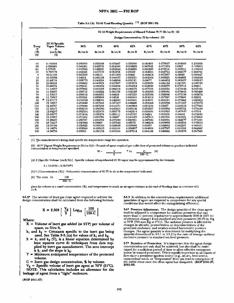
(Log #40) 2001- 35 - (Table 3-5.1 (]) (New)): Accept in Principle SUBMrlTER: Ole Bjarnsholt, Ginge-Kerr .
| RECOMMENDATION: Add a new table to 3-5: SUBSTANTIATION: Proposal for revision is submitted in order to include a new agent IG-55 in the 2001 standard. COMMITrEE ACTION: Accept in Principle. Accept the submitters recommendat ion but revise the formula in
note 4 to "S=10.0116+0.02170"t" COMMITI'EE STATEMENT: Editorial.
Table 3 - 5 . 1 ( j ) I G - 5 5 Total Flooding Q u a n t i t y
t
IG 55 Weight Requirements of Hazard Volume W / V ( lb /cu ft)
[1] The manufacturer 's listing shall specify the temperature range for operation.
[ 2] - W / V [Agent Weight Requirements ( lb /cu ft) ] = Pounds of agent required per cubic foot of protected volume to produce indicated concentration at temperature specified.
W = V * I n C [6] S 100 - C
[ 4] S [Specific Volume (cu f t / lb) ] - Specific volume of superheated IG 55 vapor may be approximated by the formula:
S = 10.0116 + 0.02170"1
[5] C [Concentration (%)] - Volumetric concentration of IG 55 in air at the temperature indicated.
[6] The term I n 100 100 - C
gives the volume at a rated concentration (%) and temperature to reach an air-agent mixture at the end of flooding time in a volume o f l oaft.
137
NFPA 2001 - - F95 ROP
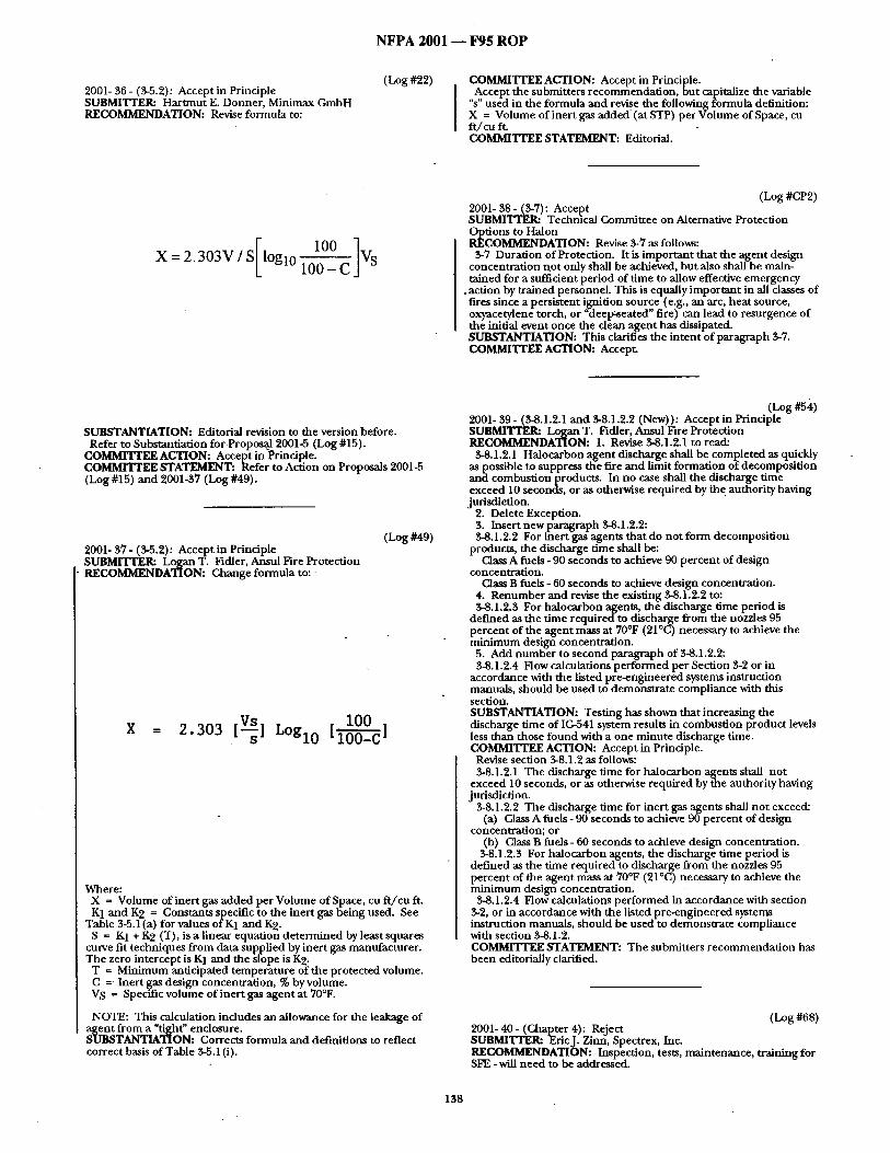
2001- 30 - (3-5.2): Accept in Principle SUBMITTEPa Hartmut E. Donner, Minimax GmbH RECOMMENDATION: Revise formula to:
(Log #22) COMMITTEE ACTION: Accept in Principle. Accept the submitters recommendat ion, but capitalize the variable
%" used in the formula and revise the following formula definition: X = Volume of inert gas added (at STP) per Volume of Space, cu f t / cu ft. COMMITTEE STATEMENT: Editorial.
I00 ] X = 2. 303V / S loglo 100- C VS
(Log #CP2) 2001- 38 - (3-7): Accept SUBMITTER: Technical Committee on Alternative Protection
~d~ tions to Halon COMMENDATION. Revise 3-7 as follows:
3-7 Duration of Protection. It is impor tant that the agent design concentrat ion no t only shall be achieved, but also shall be main- rained for a sufficient per iod of time to allow effective emergency
.action by trained personnel. This is equally important in all classes of fires since a persistent ignition source (e.g., an arc, heat source, oxyacetylene torch, or "deel~seated" fire) can lead to resurgence of the initial event once the clean agent has dissipated. SUBSTANTIATION: This clarifies the in tent of paragraph 3-7. COMMITTEE ACTION: Accept.
SUBSTANTIATION: Editorial revision to the version before. Refer to Substantiation for P ropos~ 2001-5 (Log #15).
COMMrlTEE ACTION: Accept inPrinciple . COMMITTEE STATEMENT: Refer to Action on Proposals 2001-5 (Log #15) and 2001-37 (Log #49).
2001- 37- (3-5.2): Accept in Principle SUBMITTER: Logan T. Fldler, Ansui Fire Protection RECOMMENDATION: Change formula to:
(Log #49)
X = 2 . 3 0 3 [ ~ ] L O g l 0 " 1 0 0 , s tz0-- -cJ
Where: X = Volume of inert gas added per Volume of Space, cu f t / cu ft. K1 and K 2 = Constants specific to the inert gas being used. See
Table 3-5.1 (a) for values of K1 and K 2. S = K1 + K 2 (T), is a linear equation de te rmined by least squares
curve fit techniques f rom data supplied by inert gas manufacturer. The zero intercept is K1 and the slope is K 2.
T = Minimum ant idpa ted temperature of the protected volume. C = Inert ~as design concentration, % byvolume. VS = Specific volume of inert gas agent at 70°F.
NOTE: This calculation includes an allowance for the leakage of S a ~ f rom a "tight" enclosure.
TANTIATION: Corrects formula and definitions to reflect correct basis of Table 3-5.1 (i).
(Log #53,) 2001- 39 - (3-8.1.2.1 and 3-8.1.2.2 (New)): Accept in Principle SUBMITrER: Logan T. [7idler, Ansul Fire Protection RECOMMENDATION: 1. Revise 3-8.1.2.1 to read:
5-8.1.2.1 Halocarbon agent discharge shall be completed as quickly as possible to suppress the fire and limit formation of decomposi t ion and combustion products. In no case shall the discharge time exceed 10 seconds or as otherwise required by the authority having jurisdiction.
2. Delete Exception. 3. Insert new paragraph $-8.1.2.2: $-8.1.2.2 For inert gas agents that do not form decomposi t ion
products, the discharge time shall be: Class A fuels - 90 seconds to achieve 90 percent of design
concentration. Class B fuels - O0 seconds to achieve design concenu-ation.
4. Renumber and revise the exisdng 3-8.1.2.2 to: $-8.1.2.$ For halocarbon agents, the discharge time period is
def ined as the time required to discharge from the nozzles 95 percent of the agent mass at 70°F (21°C) necessary to achieve the minimum design concentration.
5. Add number to second paragraph of 3-8.1.2.2: 3-8.1.2.4 Flow calculations per formed per Section 3-2 or in
accordance with the listed pre-engineered systems inslruction manuals, should be used to demonstrate compliance with this section. SUBSTANTIATION: Testing has shown that increasing the discharge time of IG-541 system results in combustion product levels less than those found with a one minute discharge time. COMMITTEE ACTION: Accept in Principle.
Revise section 3-8.1.2 as follows: 3-8.1.2.1 The discharge time for halocarbon agents shall not
exceed 10 seconds, or as otherwise required by the authority having jurisdiction.
3-8.1.2.2 The discharge time for inert gas agents shall no t exceed: (a) Class A fuels - 90 seconds to achieve 90 percent of design
concentration; or (b) Class B fuels - 60 seconds to achieve design concentration.
3-8.1.2.3 For halocarbon agents, the discharge t ime per iod is def ined as the time required to discharge from the nozzles 95 percent of the agent mass at 70°F (21°C) necessary to achieve the minimum design concentration.
3-8.1.2.4 Flow calculations per formed in accordance with section 3-2, or in accordance with the listed pre-engineered systems instruction manuals, should be used to demons~a te compliance with section 3-8.1.2. COMMITTEE STATEMENT: The submitters recommendat ion has been editorially clarified.
(Log #68) 2001- 40 - (Chapter 4): Reject SUBMITTER: Er icJ . Zinn, Spectrex, Inc. RECOMMENDATION: Inspection, tests, maintenance, training for SFE - will need to be addressed.
138
N F P A 2 0 0 1 m F 9 5 R O P
SUBSTANTIATION: Refer to substant iat ion for Proposal 2001-1
( c L ~ E E ACTION: Reject. COMMITTEE STATEMENT." Refer to Action on Proposal 2001-1 (Log#12).
(Log #13) 2001- 41 - (4-7.2.2.12): Accept in Principle SUBMITTER: Stephen B. Waters, NAFED RECOMMENDATION: Revise text as follows:
"The piping shall be pneumat ical ly tested in a closed circuit for a period of 10 minutes at ~,,_Q_p_.s~. At the end "
Delete "CAUTION ..." in its entirety. SUBSTANTIATION: We agree with the caut ion s t a tement for a 150 psig test. However, evacuation of areas on a construct ion site may no t be practical. Lower test pressures will achieve similar results without creating a severe safety board.
NOTE: Suppor t ing material is available for review at NFPA Headquarters . COMMITrEE ACTION: Accept in Principle.
Revise 4-7.2.2.12 (and delete the caution) as follows: 4-7.2.2.12 The piping shall be pneumatical ly tested in a closed
circuit for a per iod of 10 minu tes at 40 psig. At the end of 10 minutes , the pressure drop shall no t exceed 20 percent of the test pressure.
Exception: The pressure test shall be permi t ted to be omit ted if the total piping contains no more than one change in direction fit t ing between the storage container and the discharge nozzle, and where all piping is physically checked for t ightness. COMMITTEE STATEMENT: A pressure of 40 psig is safer and still accomplishes the intent. . of t h i s . paragraph. Reducing the pressure to a safer level and e h m m a t m g the caution makes the test more practical and encourages its implementa t ion .
(Log #14) 2001- 42- (4-7.2.2.12): Reject SUBMITTER: Stephen B. Waters, NAFED RECOMMENDATION: Delete Section 4-7.2.2.12 in its entirety. SUBSTANTIATION: The piping network is an open ended system. The flow test specified in Section 4-7.2.2.13 is adequate to insure there is no blockage. COMMI'ITEE ACTION: Reject. COMMITTEE STATEMENT: T he flow test does no t adequately address p ip ing system integrity. Refer to Action on Proposal 2001-41 (Log #13).
(Log #10) 2001- 43 - (4-7.2.4.1): Accept in Principle Note: This proposal appea red as c o m m e n t 2001-208 which was he ld
for fu r ther study f rom the F93 TCD, which was on proposal 2001-85. SUBMI'rI~I~a StevenJ. Marbes, New England Fire Equ ipmen t Co. RECOMMENDATION: Revise text as follows:
"All wir ingsystems shall be properly installed in conduit.. ." SUBSTANTIATION: Define conduit . Metal clad cable, electrical metallic tubing, in termediate conduit , rigid conduit , etc. Article 760 of NFPA 70 will allow installations with no "conduit ." i f2001 will have requ i rements beyond NFPA 70, 2001 mus t clarify what type of condui t to install. For example, is E.M.T. the m i n i m u m ? Is flexible condui t allowed? Does the condui t have to be metallic? Also, some installations canno t physically be installed in condui t because of structure.- COMMITTEE ACTION: Accept in Principle.
Revise as follows: 4-7.2.4.1 All wiring systems shall be properly installed in compli-
ance with local codes and the system drawings. AC and DC wiring shall no t be combined in a c o m m o n condui t or raceway unless pCroperly shielded a nd grounded .
OMMITTEE STATEMENT: Deleting the reference to condui t addresses the concerns of the submit ter and appropriately mainta ins the in tent of the paragraph.
(Log #25) 2001- 44 - (A-1-4.1.2): Accept in Principle SUBMITTER: Har t mu t E. Donner , Minimax GmbH RECOMMENDATION: Add a last sentence:
"The designat ion IG-100 is used in this s tandard for an u n b l e n d e d inert gas: argon."
SUBSTANTIATION: Proposal to add IG-100 to NFPA 2001. This clean agen t has been used successfially for fire protection. Refer to Substant iat ion for Proposal 2001-5 (Log #15).
COMMITTEE ACTION: Accept in Principle. Accept the suhmit ters r e c o m m e n d a t i o n hu t change IG-100 to
IG-01. COMMITTEE STATEMENT: Editorial. Refer to Action on Proposal 2001-5 (Log #15).
(Log #2 ) 2001- 45 - (Table A-l-4.1 (a)): Accept in Principle Note: This proposal appea red as c o m m e n t 2001-216 which was held
for fur ther study f rom the Fall 93 TCD, which was on proposal 2001-23. SUBMITTER: Michel N. Charette, Securiplex Technologies Inc. RECOMMENDATION: Add physical propert ies of IG-55 to this table:
Ni t rog .~ Chemical designat ion N 2 Ar Molecular weight 28.0 39.9 Boiling Point at 1 atm. -193.35°C -185.87°C Critical Tempera tu re -147.0°C -1 ~2.43°C Critical Pressure 33.9 bar 48.6 bar Densi ty at 1 a tm (15°C 1 . 1 9 k g / m 3 1.69 k g / m 3 Relative density at 1 a tm 0.967 1.38 (15°C) in relation to a tmospher ic air
SUBSTANTIATION: Physical propert ies shown in the table covers only the Halon blends. COMMITTEE ACTION: Accept in Principle. COMMITTEE STATEMENT: Refer to Action on Proposal 2001-47 (Log #41).
(Log #24) 2001- 46 - (Table A-l-4.1 (a)): Accept in Principle SUBMITTER= Harmaut E. Donner , Minimax GmbH RECOMMENDATION: Add a new co lumn to Table A-l-4.1 (a) Physical Properties of Clean Halocarbon Agents (English Units):
SUBSTANTIATION: Proposal to add IG-100 to NFPA 2001. This clean agent has been used successfully for fire protection. Refer to Substantiation for Proposal 2001-5 (Log#15).
COMMrITEE ACTION: Accept in Principle. Accept the submitters recommendation but change IG-100 to
IC,4)I. COMMITTEE STATEMENT: Editorial. Refer to Action on Proposal 2001-5 (Log #15).
(Log #41) 2001- 47 - (Table A-l-4.1 (a)): Accept SUBMrrrER: Ole Bjarnsholt, Ginge-Kerr RECOMMENDATION: Add a new column to Table A-l-4.1 (a):
IG 55
Molecular Weight 33.95 Boiling Point 760 mm Hg -310.2 Freezing Point -327.5 CriticalTemperature -210.5 Critical Pressure 602 Critical Volume N/A Critical Density N/A Specific heat, liquid 77°F N/A Specific heat, vapour constant pressure 0.187 (1 aun.) and 77~F Heat of Vaporization at Boiling Point 77.8 Thermal Conductivity of Liquid 25°C N/A Viscosity, liquid 25°C N/A Relative, dielectric strength 1 arm. 734 mm Hg 1.01 77°F (N2 = 1.0) Solubility of water in Agent 70°F 0.006% Vapour Pressure 77°F N/A
SUBSTANTIATION: Proposal for revision is submitted in order to include a new agent IG-55 in the 2001 standard. COMMITTEE ACTION: Accept.
(Log #50) 2001- 48 - (Table A-l-4.1 (a)): Accept SUBMITIT.R: Mark L. Robin, Great Lakes Chemical Corporation RECOMMENDATION: For liquid viscosity of HFC-227ea at 77°F, replace 0.547 with 0.443. SUBSTANTIATION: Revised value based upon recent measure- ments. COMMITrEE ACTION: Accept.
SUBSTANTIATION: Toxicity information on Nitrogen and Argon are already published and IG-55 figures should be no different than those. COMMYI'rRR ACTION: Accept in Principle. COMMrlTRE STATEMENT: Refer to Action on Proposal 2001-7 (Log #CP1).
(Log #26) 2001- 51 - (Table A-1-5.1.1): Accept in Principle SUBMITTER: Harunut E. Donner, Minimax GmbH RECOMMENDATION: Add to TableA-1-5.1.1 Toxicity Informa- tion:
SUBSTANTIATION: Proposal to add IG-100 to NFPA 2001. This clean agent has been used successfully for fire protection. Refer to Substantiation for Proposal 2001-5 (Log #15).
COMMITTEE ACTION: Accept in Principle. COMMrFrEE STATEMENT: Refer to Action on Proposal 2001-7 (Log #CP1). - ..
(Log #42) 2001- 52 - (Table A-1-5.1.1 ): Accept in Principle SUBMITrER: Ole Bjarnsholt, Ginge-Kerr RECOMMENDATION: Add to Table A-1-5.1.1 Toxicity Informa- tion:
SUBSTANTIATION: Proposal for revision is submitted in order to include a new agent IC-55 in the 2001 standard. COMMITrEE ACTION: Accept in Principle. COMMI'VI'EE STATEMENT: Refer to Action on Proposal 2001-7 (Log #CP1 ).
(Log #57) 2001- 49 - (Table A-l-4.1 (b)): Accept SUBMITTEPa Mark L Robin, Great Lakes Chemical Corporation RECOMMENDATION: For liquid viscosity of HFC-227ea at 25°C, replace 0.226 with 0.184. SUBSTANTIATION: Revised value based upon recent measure- ments. COMMITTEE ACTION: Accept.
(Log #3) 2001- 50 - (A-I-5.1.1): Accept in Principle Note: "This proposal appeared as comment 2001-223 which was held
for further study from the Fall 93 TCD, which was on proposal 2001-23. SUBMITTRR: Michel N. Charette, Securiplex Technologies Inc. RECOMMF~DATION: Add toxicity information on IG-55.
(Log #CP3) 2001- 53 - (Table A-I-5.1.1): Accept SUBMITIYR: Technical Committee on Alternative Protection
~j~ tious to H'alon COMMENDATION: Revise the NOAEL value of HBFC-22B1 to
0.3% and the LOAEL value of HBFC-22B1 to 1.0%. Revise the LOAEL value of I-IFC-227ea to >10.5%. SUBSTANTIATION: This provides updated values and is consistent with the U.S. EPA SNAP list. Refer to Action on Proposal 2001-7 (Log #CP1). COMMrrrEE ACTION: Accept.
140
N F P A 2001 - - F 9 5 R O P
2001- 54- (Figure A-2-1.2.1(k) (New)): Accept SUBMITTER: Ole Bjamsholt, Ginge-Kerr RECOMMENDATION: Add new Figure A-2-1.2.1 (k):
(Log #44)
2700 /
/ 2600
/ /
25O0 / A /
~ 2 4 0 0 /,
" /
2200" /
2100 ~/
200O 0
/ /
20 40 60 80 100 120 140
Temperature (*F)
SUBSTANTIATION: Proposal for revision is submitted in order to include a new agent IG-55 in the 2001 standard. COMMITTEE ACTION: Accept. °
(Log #27) 2001- 55 - (A-2-1.4.1): Accept SUBMITTER: Harunut E. Donner, Minimax GmbH RECOMMENDATION: Revise first sentence of clause 3:
"With the exception of inert gas-type systems, all of the other clean agents are classified as liquefied compressed gases at 70°F (21°C)." SUBSTANTIATION: Change "1G-541" against "inert gas-type systems." The revised text includes all inert gas agents.
Refer to Substantiation for Proposal 2001-5 (Log #15). COMMITI'F.~ ACTION: Accept.
(Log #43) 2001- 56 - (A-2-1.4.1): Accept in Principle SUBMITTER: Ole Bjarusholt, Ginge-Kerr RECOMMENDATION: Change first sentence ofA-2-1.4.1 para-
~Wiaph 3: th the exception of IG 541, IG 100 and IG 55, all of the other clean agents are classified as liquefied compressed gases at 70°F (21°C). " SUBSTANTIATION: Proposal for revision is submitted in order to include a new agent IC,-55 in the 2001 standard. COMMITrE~ ACTION: Accept in Principle. COMMITI'EE STATEMENT: Refer to Action on Proposal 2001-55 (Log #27).
(Log #59) 2001- 57 - (Figure A-2-1.4.1 (New)): Accept SUBMITTER: Mark L Robin, Great Lakes Chemical Corporation RECOMMENDATION: Add following Figure:
24OO
1200 : .=
IOO0
80O
60O
400
/ /
/ / / i /
/ / / / / /
A
20
+ 70 IbRl 3
.
les t ~
i /
[ ' ~ Ib /~
40 60 80 100 120 140 160 180 200 Temperature (°F)
F'tgure A-2-1.4.1 Isometric Diagram of HFC-227ea Pressurized to 600 psig withNitrogen at 70°F
SUBSTANTIATION: Required information for design of 600 psig HFC-227ea systems. COMMITTEE ACTION: Accept.
(Log #58) 2001- 58 - (Figures A-2-1.4.1 (a), (b), (e), and (g)): Accept SUBMITTER: Mark L. Robin, Great Lakes Chemical Corporation RECOMMENDATION: In Figures A-2-1.4.1(a), (b), (e) and (g), replace "mPa" with "MPa." SUBSTANTIATION: Correct abbreviation for Megapascals is MPa; editorial. COMMITTEE ACTION: Accept.
(Log #CP4) 2001 - 59 - ( Figu re A-2-1.4.1 (g) ): Accept SUBMITYER= Technical Committee on Alternative Protection
~ tions to Halon COMMENDATION: Delete "Pressurized to" in the caption for
S~L~e A-2-1.4.1 (g). TANTIATION: Editorial.
COMMI'ITEE ACTION: Accept.
141
N F P A 2 0 0 1 - - F 9 5 R O P
(Log #28) 2001- 60 - (Fi~resA-2-1.4.1 (h) and (i) (New)): Accept in Principle SUBMITTEI~ Hartmut E. Donner, Minimax GmbH RECOMMENDATION: Add Figure A-2-1.4.1 (h) and Figure A-2-1.4.1 (i):
SUBSTANTIATION: Proposal to add IG-I00 to NFPA'2001. This clean agent has been used successfully for fire protection. Refer to Substantiation for Proposal 2001-5 (Log #15).
COMMITTEE ACTION: Accept in Principle. Accept the submitters recommendation but change IG-100 to
IG-01. Also revise the captions for each figure by deleting the words reSsurized to".
MMITrEE STATEMENT: Editorial. Refer to Action on Proposal 2001-5 (Log #15).
28O0
2700
2600
.~ 2500 /
| , / o. 2300 ¢
/ 2200 J
/
2100 /
2OOO 0
/ /
/ /
20 40 60 80 100 120 140 Temperature (°F)
Figure A-2-1.4.1 (h) Isometric diagram of IG100 (pressurized to 2370 psi at 70°F) [English Units]
19
18
17
- i
O .
15
/ 14
-20
/ /
/ /
l i i l i !
ill|il l l l l l l
/ /
/ /
/
-10 0 10 20 30 40 50 60 Temp~atum (°C)
Figure A-2-1.4.1(i) Isometric diagram of IGLOO (pressurized to 160 ' " bar at 15°C) [SI units]
(Log #52) 2001- 61 - (A-2-1.4.2): Accept in Principle SUBI~TTER: Logan T. Fidler, Ansul Fire Protection RECOMMENDATION: 1. Add "halocarbon" before "agent" in entire paragraph.
2. Add new paragraph: "Inert gas agents are naturally recycling since a discharge results in
a return of the agent to its original source, the atmosphere." SUBSTANTIATION: Differentiates importance of recycling halocarbon agents to minimize environmental impact and inert gas
ents comprised of naturally occurring gases. MMITrEE ACTION: Accept in Principle.
1. Add "halocarbon" before "agent" in entire paragraph. 2. Add a new second paragraph: "Inert gas agents need not be collected or recycled."
COMMITrEE STATEMENT: The revised wording meets the intent of the submitter and is consistent with the current wording of the paragraph.
(Log #29) 2001- 62 - (A-2-2.1.1): Accept in Principle SUBMITTER: Harmmt E. Donner, Minimax GmbH RECOMMENDATION: Add following sentences to point 4:
"For IG-100 systems, the calculated pressure P, must be equal to or greater than:
2650 psi for piping upstream of the pressure reducer. 975 psi for piping downstream of the pressure reducer."
SUBSTANTIATION: Proposal to add IG-100 to NFPA 2001. This clean agent has been used successfully for fire protection. Refer to Substantiation for Proposal 2001-5 (Log #15).
COMMITTEE ACTION: Accept in Principle. Accept the submitters recommendation but change IG-100 to
IG-01. COMMITTEE STATEMENT: Editorial. Refer to Action on Proposal 2001-5 (Log #15).
(Log #45) 2001-63- (A-2-2.1.1): Accept in Principle SUBMITTER: Ole Bjamsholt, Ginge-Kerr RECOMMENDATION: Add following sentences to A-2-2.1.1:
"For IG 55 systems, the calculated pressure P, must be equal to or greater than:
2480 psi. for ppi ing upstream of the pressure reducer. 450 psi for plpmg downstream of the pressure reducer. The pressure values are based on a maximum agent storage
temperature of 130°F (55°C)." SUI~TANTIATION: Proposal for revision is submitted in order to include a new agent IG-55 in the 2001 standard. COMMITTEE ACTION: Accept in Principle. Accept the submitter recommendation but revise the values 450 to
950. COMMITI'EE STATEMENT: This provides consistency with Proposal 2001-20 (Log #37).
(Log #30) 2001- 64- (A-2-2.3.1 (e) (New)): Accept in Principle SUBMITTER: Hartmut E. Donner, Minimax GmbH RECOMMENDATION: Add a new clause to A-2-2.3.1:
(e) Fittings for IG-100 systems having a charging pressure of 2370 psig at 70°F (21°C) should be, as a minimum:
Upstream of the pressure reducer: 3000-1b Class forged steel, in all sizes.
Downstream of the pressure reducer: Class 300 malleable or ductile iron fi~dngs through 3 in. NPS, and 1000-1b rated ductile iron or forged steel fittings in all larger sizes. Flanged joints should be Class 600.
142
N F P A 2 0 0 1 - - F 9 5 R O P
The materials itemized above do not preclude the use of other materials and type and style of fittings that satisfy the requirements of 2-2.3.1. SUBSTANTIATION: Proposal to add IG-100 to NFPA 2001.
This clean agent has been used successfully for fire protection. Refer to Substantiation for Proposal 2001-5 (Log #15).
COMMITFEE ACTION: Accept in Principle. Accept the submitters recommendation but insert as a new
paragraph (c) and redesignate subsequent paragraphs accordingly. Also change IG-100 to IG-01. COMMITITEE STATEMENT: Editorial. Refer to Action on Proposal 2001-5 (Log #15).
(Log #46) 2001- 65 - (A-2-2.3.1 (e) (New)): Accept in Principle SUBMITTER: Ole Bjarnsholt, Ginge-Kerr RECOMMENDATION: Add a new clause A-2-2.3.1 (e):
(e) Fittings for IG 55 systems having a charging pressure of 2175 psig at 70°F (21°C) should be, as a minimum:
Upstream of the pressure reducer: 3000-1b Class forged steel/in all sizes•
Downstream of the pressure reducer: Class 300 malleable or ductile iron fittings through 3 in. NIPS, and 1000-1b rated ductile iron or forged steel fittings in all larger sizes• Flanged joints should be Class 600. The material itemized above do not preclude the use of other
materials and type and style of fittings that satisfy the requirements of 2-2.3.1. SUBSTANTIATION: Proposal for revision is submitted in order to include a new agent IG-55 in the 2001 standard. COMMITrEE ACTION: Accept in Principle. Accept the submitters recommendation but insert as a new
paragraph following the new paragraph that has been inserted by Proposal 2001-64 (Log #30). Redesignate subsequent paragraphs accordingly. COMMITrEE STATEMENT: Editorial.
(Log #55) 2001- 66 - (A-3-3.3 (New)): Reject SUBMITTER: Logan T. Fldler, Ansul Fire Protection RECOMMENDATION: Add new paragraph with text the same as NFPA 12A, A-3-3.3 with appropriate changes to reflect agents covered by this standard: A-3-3.3 The design of total flooding halocarbon agent systems only
beneath the raised floor of EDP facilities when the occupied space above the raised floor is not similarly protected by a total flooding halocarbon agent system does not meet the intent of this standard.
Inert gas agents that do not form products of decomposition may be used in total flooding systems protecting only beneath the raised floor of I~DP facilities. SUBSTANTIATION: NFPA 12A recognized the danger of less than extinguishing concentrations of 1301 occurring above the raised floor due to agent loss. Should a fire occur above the floor such as in a piece of equipment, failure to achieve design extinguishing concentration will result in the potential to produce unacceptable levels of products of decomposition.
Inert gas agents that do not form products of decomposition may be used in raised floor only systems because the potential unaccept- able levels of decomposition products will not occur. COMMITrEE ACTION: Reject.
• COMMrrrEE STATEMENT: This topic is presently under review by the Standards Council regarding the jurisdictional scope between the NFPA 12A Committee and the NFPA 75 Committee. The submitter is encouraged to resubmit a public comment on this matter when the jurisdictional issue is resolved. Furthermore, no data has been provided that supports the submitter's recommenda- tion.
(Log #60) 2001- 67 - (Table A-3-4.2.1): Accept S U B M I T I ' E R : Mark L. Robin, Great Lakes Chemical Corporation RECOMMENDATION: Add following inert concentrations for HFC-227ea to Table A-3-4.2.1:
SUBSTANTIATION: Required information.for proper design of HFC-227ea systems for inertion of listed fuels. COM]~TrEE ACTION: Accept.
(Log #61) 2001- 68 - (Table A-3-4.2.2 (New)): Accept in Principle SUBMITTER: Mark L. Robin, Great Lakes Chemical Corporation RECOMMENDATION: Include new table listing cup burner extinguishing values for listed fuels with HFC-227ea:
HFC-227ea Extinguishing Concentrations
Fuel Cup Burner Extinguishing Concentration, % v / v
SUI~TANTIATION: Required information for proper design of systems for protection of the listed fuels• C O M M I T F E E A C T I O N : Accept in Principle. Accept the submitters recommendation, but add a note as follows: ~NOTE: Information supplied by mannfacturer (GLCC)."
COMMrlTEE STATEMENT: This provides additional information.
143
NFPA 2001 - - F95 R O P
(Log #1) 2001- 69 - (A-3-4.3 (New)): Accept in Principle Note: This proposal appeared as comment 2001-265 which was held
for fur ther study from the Fall 93 TCD, which was on proposal 2001-1. SLrBMITTER: PhilipJ. DiNenno, Hughes Associates, Inc. RECOMMENDATION: Add description of fire test methods used to evaluate extinguishing concentrat ion for Class A fuels. These tests should be those used by independen t testing laboratories in developing listings. SUBSTANTIATION: A description of test methods used by independen t test laboratories in listing clean agent systems. COMMITTEE ACTION: Accept in Principle.
(3hange 3-4.2.2.1 to 3-4.2.2.1" Insert a new A-34.2.9.1 as follows: A-3-4.Z2.1 Fire Ext inguishment /Area Coverage Fire Test
Procedure for Engineered and Preengineered Clean Agent Extinguishing System Units.
(a) General Requirements. (i) An engineered or. p reengineered extinguishing system should
mix and distribute its extinguishing agent and shall totally flood an enclosure when tested in accordance with the recommendat ions of (iii) through (xvii) under the maximum design limitations and most severe installations instructions. See also (ii).
(ii) When tested as described in (iv) th rough (xi), an extinguish- ing system unit should extinguish all fires within 30 seconds after the end of discharge. When tested as described in (iv) through (viii) and (xii) through (xvii), an extinguishing system should prevent reignition of the wood crib after a 10 minute soak period.
(iii) The tests described in (iv) through (xvii) consider the in tended use and limitations of the extinguishing system, with specific reference .to (1) the area coverage for each type of nozzle; (2) the operating temperature range of the system; (3) location of the nozzles in the protected area; (4) ei ther maximum length and size of piping and number of fittings to each nozzle, or min imum nozzle pressure; (5) maximum discharge time; and (6) maximum fill density.
(b) Test Enclosure. (iv) The enclosure for the test should be constructed o f e i ther
indoor or outdoor grade min imum 9.5 mm (3/8 inch) thick plywood or equivalent material.
(v) An enclosure(s) is to be constructed having (1) the maximum area coverage for the extinguishing system unit or nozzle being tested, a nd ( 2 ) the min imum and maximum protected area height limitations.
Exception: The test enclosure(s) for the maximum height, flammable liquid and wood crib fire ext inguishment tests need no t have the maximum coverage area but shall be at least ten feet wide by ten feet long.
(c) Extinguishing System. (vi) A preengineered type extin~uishi'ng system unit is to be
assembled using its maximum piping limitations with respect to number of fittings and length of pipe to the discharge nozzles and nozzles configuration(s) as specified in the Manufacturer Design and Installation Instructions.
(vii) An engineered-type extinguishing system unit is to be assembled unsing a p ip inga r r angemen t that results in the min imum nozzle design pressure at70°F (21°(3).
(viii) Except for the flammable liquid fire test using the 2-1/2 ft pan and the wood crib ext inguishment test, the cylinders are to be condi t ioned ot the min imum operating temperature specified in the manufacturer 's installation instructions.
(d) Extinguishing Concentrat ion (ix) The extinguishing agetn concentrat ion for each test is to be
83.34 percent o f the in tended end use design concentration specified in the Manufacturer 's Design and Installation Instructions at the ambient temperature 9 f t h e enclosure. The concentrat ion fo r inert gas clean.agents may be adjusted to take into consideration actual leakage measured f rom the ' test enclsoure. The concentrat ion within the enclosure for halocarbon clean agents shall be calculated using the following formula unless it is demonstra ted that the test enclosure exhibits significatn leakage. If significant test enclosure leakage does exist, the formula used to de termine the test enclosure concentrat ion halocarbon clean agents can be modif ied to account for the leakage measured.
Halocarbon Glean Agents
Where: W = Weight of dean agents, Ib V = Volume of test enclsoure, ft3 S = Specific volume of d e a n agent at test temperature (ft$/Ib) (3 = Concentration, percent
(e) Flammable Liquid Extinguishment Tests (x) Test cans, 3.0 to 3.5 in. (76.9 mm to 88.9 mm) in diameter and
at least 4 in. (102 mm) high, containing either heptane or heptane and water, a re to be placed within 2 in. (50.8 mm) of the corners of the test enclosure(s) and directly behind the baffle (see below), and located vertically within 12 in. (305 mm) of the top or bottom fo the enclosure, or both top and bot tom if the enclosure permits such placement. If the cans contain heptane and water, the heptane is to be at least 2 in. (50.8 mm) deep. The level of 'heptane in the cans shall be at least 2 in. (50.8 r am)be low the top of the can. In addition, for the min imum height limitation area coverage test,.a baffle is to be installed between the floor and ceiling in the center of the enclosure. The baffle is to be perpendicular to the direction fo nozzle discharge, and be 20 percent o f the length or width of the enclosure, whichever is applicable with respect to nozzle location. For the maximum room height extinguishment test, an additional test shall be conducted using a 2-1/2 ft2 (0.23 m2g) square pan located in the center of the room and the storage cylinder condi- t ioned to 70°F. The test pan is to contain at least 2 in. (50.8. ram) of heptane with the heptane level at least 2 in. below the top of the pan. The heptane is to be ignited and allowed to burn for 30 s, after whicht eh extinguishing system is to be manually actuated. At the time of actuation, the percent of oxygen within the enclosure shall be at least 20.0 percent.
(xi) The heptane is to be commercial grade having the following characteristics:
Distillation - Initial boiling point 90°(3 (194°F) 50 percent 93°(3 (199°F) Dry point 96.5°(3 (208017 )
Specific gravity (60°F/60°F) 0.719 (15.6°(3/15.6°(3)
Reid vapor pressure 2.0 psi Research octane rating 60 Motor octane rating 50
(f) Wood Crib Extinguishment Tests (xii) The storage cylinder is to be condi t ioned to 70°F. The test
enclosure is to have the maximum ceiling height as specified in the manufacturer 's installation instructions.
(xiii) The wood crib is to consist of four layers of six, trade size 2 by 2 (1-1/2 by 1-1/2 in.) by 18 in. long, kiln spruce or fir lumber having a moisture conten t between 9 and 13 percent. The alternate layers of the wood members are to be placed at right angles to one another. The individual wood members in each layer are to be evenly spaced in forming a square de te rmined by the specified length of the wood members. The wood members forming the outside edges of the crib are to be stapled or nailed togehter.
(xiv) Ignition of the crib is to be achieved by the burning of commercial grade heptane in a square steel pan 2-1/2 ft2 in.area and no t less than 4 in. in height. The crib is to be centered with the bot tom of the crib 24 in. above the top of the pan and the test stand constructed so as to allow for the bot tom of the crib to be exposed to the atmosphere.
(xv) The heptane is to be ignited and the crib is to be allowed to burn freely for approximately 6 min. outside the test enclosure. Just Pthrior to the end of the p reburn period, the crib is to be moved into
e test enclosure and placed on a stand such that the bot tom of the crib is between 20 and 28 in. above the floor. The enclosure is then to be sealed.
(xvi) After allowing the crib to burn for a per iod of 6 min., the system is to be actuated. At the time of actuation, the percent oxygen within the enclosure at the level of the crib shall be at least 20.0 l~.ercent.
(xvti) After the end of system discharge, the enclosure is to remain sealed for a total of 10 rain. After the 10 min. soak period, the crib is rob e removed from the enclosure, observed to determine that sufficient rnel remains to sustain combustion and for signs of reignition. COMMITTEE STATEMENT: The added section addresses the submitters concerns and meets the sub. mitters intent.
V C S 100.
144
N F P A 2 0 0 1 m F 9 5 R O P
(Log #31) 2001- 70 - (A-4-7.2.2.13): Accept in Principle SUBMITTER: Harunut E. Donner, Minimax GmbH RECOMMENDATION: 1. Add a new clause 4:
"For inert gas-type systems the flow test should be performed using original agent. The quantity of agent used for this test should be suttlcient to verify that each and every nozzle is unobstructed."
2. Revise last clause to: "Visual indicators should be used to verify that test medium has
discharged out of each and every nozzle in the system." SUBSTANTIATION: Proposal to add IG-100 to NFPA 2001. This clean agent has been used successfully for fire protection. Refer to Substantiation for Proposal 2001-5 (Log #15).
COMMITI'EEACTION: Accept in Principle. Revise 4-7.2.2.13 as follows: 4-7.2.2.13" A flow test using nitrogen or an inert gas shall be
performed on the piping network to verify that flow is continuous, and that the piping and nozzles are unobstructed.
Revise A-4-7.2.2.13 as follows: A-4-7.2.2.13 Piping Network Flow Test. The purpose is to conduct
a flow test of short duration (also known as a "puff test") through the piping network to determine that (1) the flow is continuous, (2) check valves are properly ori'ented, and (3) the piping and nozzles are unobstructed.
The flow test should be performed using gaseous nitrogen or an inert gas at a pressure not to exceed the normal operating pressure of the clean agent system. The nitrogen or an inert gas pressure should be introduced into
the piping network at the clean agent cylinder connection. The quantity of nitrogen or an inert gas used for this test should be sufficient to verify that each and every nozzle is unobstructed. Visual indicators should be used to verify( that nitrogen or an inert
gas has discharged out of each and every hozzle in the system. COMMITI'EE STATEMENT: These changes more appropriately address the concerns of the submitter.
(Log #32) 2001- 71 - (Table B-2-7.1.4): Accept in Principle SUBMITTER: Hartmut E. Donner, Minimax GmbH
I RECOMMENDATION: Add to Table:
IG-100 1.70 kg/m3 (0.106 lb/ft3)
SUBSTANTIATION: Proposal to add IG-100 to NFPA 2001. This clean agent has been used successfully for fire protection. " Refer to Substantiation for Proposal 2001-5 (Log #15).
COMMITrEE ACTION: Accept in Principle. Accept the submitters recommendation but change IG-100 to
IG-01. COMMITI'EE STATEMENT: Editorial. Refer to Action on Proposal 2001-5 (Log #15).
(Log #47) 2001- 72 - (Table B-2.7.1.4): Accept SUBMITTER: Ole Bjarnsholt, Ginge-Kerr RECOMMENDATION: Add a new line to Table B-2.7.1.4:
IG 55 1.41 kg/m3 (0.088 lb/ft3) SUBSTANTIATION: Proposal for revision is submitted in order to include a new agent IG-55 in the 2001 standard. COMMITrEE ACTION: Accept.
The following draft of NFPA 2001-1996 incorporates the Committee Actions on Public Proposals that make up the Techoical Committee Report and that appear on the preceding pages. The draft is presented only as an aid to the reviewer.
NFPA 2001
Standard on
Clean Agent Fire Extinguishing Systems
1996 Edition
NOTICE: An asterisk (*) following the number or letter designating a paragraph indicates explanatory material on that paragraph in Appendix A-
Information on referenced publications can be found in Chapter 5 and Appendix C.
Chapter I General
1-1 Scope. This standard contains minimum requirements for total flooding, clean agent fire extinguishing systems.It does not cover fire extinguishing systems that use carbon dioxide, Halon 1301, Halon 1211, Halon 2402, or water, which are addressed by other NFPA documents.
1o2 Purpose.
1-2.1 The agenls in this standard were introduced in response to international resu'ictions on the production of certain halon fire extinguishing agents under the Montreal Protocol signed September 16, 1987, as amended. This standard is prepared for the use and guidance of those charged with purchasing, designing, installing, testing, inspecting, approving, listing, operating, and maintaining engineered or pre-engineered clean agent extinguishing systems, so that such equipment will function as intended throughout its life. Nothing in this standard is intended to restrict new technologies or alternate arrangements provided the level of safety prescribed by this standard is notlowered.
1-2.2 No standard can be promulgated that will provide all the necessary criteria for the implementation of a total flooding, clean agent fire extinguishing system. Technology in this area is under constant development, and this will be reflected in revisions to this standard. The user of this standard must recognize the complexity of clean agent fire extinguishing systems. Therefore, the designer is cautioned that the standard is not a design handbook. The standard does not do away with the need for the engineer or for competent engineering judgment. It is intended that a designer capable of applying a more complete and rigorous analysis to special or unusual problems shall have latitude in the development of such designs. In such cases, the designer is responsible for demonstrating the validity of the approach.
1-3 Definitions and Units.
1-3.1 Definitions. For purpose of clarification, the following general terms used with special technical meanings in this standard are defined:
Approved.* Acceptable to the authority having jurisdiction.
Authority HavingJurlsdictlon.* The organization, office, or individual responsible for approving equipment, an installation, or a procedure.
Clean Agent. Electrically nonconducting, volatile, or gaseous fire extinguishant that does not leave a residue upon evaporation. The word "agent" as used in this document shall mean "clean agent" unless otherwise indicated.
Clearance. The air distance between clean agent equipment, including piping and nozzles, and unenclosed Or uninsulated live electrical components at other than ground potential.
Engineered Systems. Those requiring individual calculation and design to determine the flow rates, nozzle pressures, pipe size, area or volume protected by each nozzle, quantity of clean agent, and the number and types of nozzles and their placement in a specific system.
145
NFPA 2001 - - F95 RO P
F'dl Densi~. The ,~ass of clean agent per unit of container volume (e.g., lb/ft", kg/m ).
Halocarbon ent. A clean agent that contains as primary A g . . .
components one or more organic compounds contmnlng one or more of the elements fuorine, chlorine, bromine, or iodine. Examples are bydrofluorocarbons (HFCs), bydrochlorofluorocarbons (HCFCs), and perfiuorocarbons (PFC~).
Inert Gas Agent. A clean agent that contains as primary compo- nents one or more of the gases helium, neon, argon, or nitrogen. Inert gas agents that are blends of gases can also contain carbon dioxide asa secondary component. (ROP 2001-2)
Listed.* Equipment or materials included in a list published by an organization acceptable to the authority having jurisdiction and concerned with product evaluation that maintains periodic inspection of production of listed equipment or materials and whose listing states either that the equipment or material meets appropri- ate standards or has been tested and found suitable for use in a specified manner.
No Observed Adverse Effect Level~ The highest concentration at which no adverse toxicological or physiological effect has been observed.
NOAEL. See No Observed Adverse Effect Level.
Normally Occupied Area.* One that is intended for occupancy.
Pre-Engineered Systems. Those having predetermined flow rates, nozzle pressures, and quantities of clean agent. These systems have the specific pipe size, maximum and minimum pipe lengths, flexible hose specifications, number of fittings, and number and types of nozzles prescribed by a testing laboratory. The hazards protected by these systems are specifically limited as to type and size by a testing laboratory based upon actual fire tests. Limitations on hazards that can be protected by these systems are contained in the manufacturer's installation manual, which is referenced as part of the listing.
Shall. Indicates a mandatory requirement.
Should. Indicates a recommendation or that which is advised but not required.
Superpressurization. The addition of a gas to the fire suppression agent container necessary to achieve the pressure required for proper system operation.
Total Flooding. A system consisting of a supply of clean agent arranged to discharge into, and fill to the proper concentration, an enclosed space or enclosure about the hazard.
1-3.2 Units.
1-3 2 1 Metric units of measurement in this standard are in • • . . i
accordance with the modermzed metric system known as the International System of Units (SI). Two units (liter and bar), outside of but reco~[nized by SI, are commonly used in international fire protection, lhese units are listed in Table 1-3.2 with conversion factors.
1-3.2.2 If a value for measurement as given in this standard is followed byan equivalent value in other units, the first stated is to be regarded as the requirement. A given equivalent value might be approximate.
1-4 General Information.
t-4.1" Applicability of Clean Agents.
1-4.1.1 The clean agents addressed in this standard are electrically nonconductive agents that extinguish fires and leave no residue upon evaporation.
1-4.1.2" Clean agents that meet the criteria of 1-4.1.1 and are diseussed in this standard are shown in Table 1-4.1.2.
Table 1-$.2 Metric Co-version Factors
Name of Unit Ualt Symbol Conversion Factor
millimeter mm 1 in. - 25.4 mm fiter L 1 gad = 3.785 L cubic decimeter dm s 1 8"41_ - 3.785 dm s cubic meter m s 1 ft s -- 0.028317 m s kilogram kg 1 lb ~ 0.4536 kg kilograms per
cubic meter kg/m s 1 lb/ft s -- 16.0183 kg/m s pascal Pa 1 psi = 6895 Pa
"bar bar I psi ~ 0.0689 bar bar bar l b a r = 10SPa • i i l l i | , l i
NOTE 1: For additional converaiona and information ~ .~TM E380, Sta~/ar&for M~/c P n u ~ . NOTE 2: In Canada refer to Camad~ Ma6c Pma/~ Gu~, CSA Standard CANS-Z234.1-89.
(ROP 2001-4, 2001-5, 2001-6)
Table l-4k I.~ Cleam A g m Addrnm~ ia ~ 5nmdKd
FC~3-1-10 Perfluorobutane C4FI0 HBFC-22B1 Bmm&lifluoromethane CHF2Br HCFC Blend A Dichlorotrifluoroethane CHCI2GF s
HCFC-I~$ (4.75%) Chlorodilluoromethane
HCFC-22 (89%) CHCIF 2 Chlorotetrafluoroethane
HCFC-124 (9.5%) CHCIFCF s Isopropenyl-l-
methylcydohexene (3.75%)
HCFC-124 Chlorotetrafluoroethane CHCIFCF a HFC-125 Pentafluoroethane CHF2CF 5 HFC-297ea Heptafluoropropane CFqCHFCF s HFC-23 Trifluoromethane CHF s 10.01 Argon (99.9%) Ar 10-541 Nitrogen (52%) N 2
Argon (40%) Ar Carbon dioxide (8%) CO 2
10-55 Nitrogen (50%) N~ Argon (50%) Ar
NOTE 1: Other agenm might become avallable at later dmeL They might be added via the NFPA proa~ in fama~ editions or ammadmentl of the standanL NOTE 2: Compmition of IG-S41 I- given in percent by volume. Compmi- tlon of HCFC Blend A is given in percent by weight.
14.1.3 The design, installation, service, and maintenance of clean agent systems shall be performed by those skilled in clean agent fire extinguishing system technology.
1-4.2 Use and Limitations.
1-4.2.1 Preqengineered systems consist of system components designed to be installed according to pretested limitations as listed by a testing laboratory. Pre-engineered systems might incorporate special nozzles, flow rates, methods of application, nozzle placement, and pressurization levels that might differ from those detailed elsewhere in this standard. All other requirements of the standard apply. Pre-engineered systems shall be installed to protect hazards within the limitations that have been established by the testing laboratories where listed.
1-4.2.2 Glean agent fire extinguishing systems are useful within the limits of this standard in extinguishing fires in specific hazards or equipment and in occupancies where an electrically nonconductive medium is essential or desirable, or where cleanup of other media presents a problem.
146
N F P A 2001 - - F 9 5 R O P
1-4.2.3" Total flooding, clean agent fire extinguishing systems are used primarily to protect hazards that are in enclosures or equip- ment that, in itself, includes an enclosure to contain the agent Some typical hazards that might be suitable include, but are not limited to, the following: (ROP 2001-27)
(a) Electrical and electronic hazards;
(b) Telecommunications facilities;.
(c) Flammable and combustible liquids and gases; and
(d) Other high value assets.
1-4.2.4" Clean agent systems might also be used for explosion prevention and suppression where flammable materials might collect in confined areas.
14.2.5 Clean agents shall not be used on fires involving the following materials unless they have been tested to the satisfaction of the authority havingjurisdicti6n:
(a) Certain chemicals or mixtures of chemicals, such as cellulose nitrate and gunpowder, that are capable of rapid oxidation in the absence of air;
(b) Reactive metals such as lithium, sodium, potassium, magne- sium, titanium, zirconium, uranium, and plutonium;
(c) Metal hydrides; or
(d) Chemicals capable of undergoingautothermal decomposition, such as certain organic peroxides and hydrazine.
1-4.2.6 Electrostatic charging of nongrounded conductors might occur during the discharge of liquefied gases. These conductors might discharge to other objects, causing an.electric arc of sufficient energy to initiate an explosion. (SeeNFPA 77, Recommended Practice on Static Electricity.)
1-4.2.7 Where clean agent systems are used, a fixed enclosure shall be provided about the hazard that is adequate to enable the specified concentration to be achieved and maintained for the specified period of time.
1-4.2.8" The effects of agent decomposition on fire protection effectiveness and ecluipment shall be considered where using clean agents in hazards vmh high ambient temperatures (e.g., furnaces and ovens).
1-5 Safety.
1-5.1" Hazards to Personnel. (ROP 2001-7)
* 1-5.1.1 Any agent that is to be recognized by this standard as acceptable for use in normally occupied spaces shall first be evaluated in a manner equivalent to the process used by the U.S. Environmental Protection Agency's SNAP Program.
NOTE: The U.S. Environmental Protection Agency's SNAP Program was originally outlined in Federal Register 59 FR 13044.
1-5,1.2" Halocarbon Clean Agents.
1-5.1.2.1 Unnecessary exposure to all halocarbon clean agents and their decomposition products shall be avoided. Halocarbon agents for which the design concentration is equal to or less than the NOAEL shall be permitted for use in normally occupied areas. Halocarbon agents for which the design concentration is greater than the NOAEL shall not be permitted for use in normally occupied areas.
1-5.1.2.2 To maintain oxygen concentrations above 16 percent (sea level equivalent), the point at which onset of impaired personnel function occurs, no halocarbon fire extinguishing agents of concentration greater than 24 percent addressed in this standard shall be used in a normally occupied area.
1-5.1.3" Inert Gas Clean Agents. No inert gas agent with a design concentration above 43 percent, which corresponds to an oxygen concentration of 12 percent (sea level equivalent), shall be permitted for use in normally occupied areas.
* 1-5.1.4 Safety Requirements. For fire situations, suitable safe- guards shall be provided to ensure prompt evacuation of and prevent entry into hazardous atmospheres and also to provide means
for prompt rescue of any gapped personnel. Safety items such as personnel training, warning signs, discharge alarms, self-contained breathing apparatus, evacuation plans, and fire drills shall be considered.
1-5.2 Electrical Clearances.
1-5.2.1 All system components shall be located to maintain no less than minimum clearances from energized electrical parts. The following references shall be considered as the minimum electrical clearance requirements for the installation of clean agent systems:
(a) ANSI C-2, National Electrical Safety Code
(b) NFPA 70, NationalElectrical Code~
(c) 29 CFR 1910 Subpart S.
1-5.2.2 Where the design basic insulation level (BIL) is not available, and where nominal voltage is used for the design criteria, the highest minimum clearance listed for this group shall be used.
1-5.2.3 The selected clearance to ground shall satisfy the greater of the switching surge or BIL duty, rather than being based on nominal voltage.
1-5.2.4 The clearance between uninsulated energized parts of the electrical system equipment and any portion of the clean agent system shall not be less than the minimum clearance provided elsewhere for electrical system insulations on any individual component.
1-5.2.5 Where BIL is not available and where nominal voltage is used for the design criteria, the highest minimum clearance listed for this group shall be used.
1-6" Environmental Factors. When an agent is being selected to protect a hazard area, the effects of the agent on the environment shall be considered. Selection of the appropriate fire suppressant agent shall include consideration of the following items:
a~(~ Potential environmental effect of a fire in the protected area;
(b) Potential ehvironmental effect of the various agents that may be used.
1-7 Retrofitabifity. Retrofitting of any clean agent into an existing fire extinguishing system shall result in a system that is listed or approved.
1-8 Compatibility with Other Agents.
1-8.1" Mixing of clean agents in the same container shall be permitted only if the system is listed.
1-8.2 Systems employing the simultaneous disqharge of different clean agents to protect the same enclosed space shall not be permitted.
Chapter 2 Components
2-1 Agent Supply.
2-1.1 Quantity.
2-1.1.1 The amount of clean agent in the system shall be at least sufficient for the largest single hazard protected or group of hazards that are to be protected simultaneously. This quantity of agent is defined as the primary agent supply.
2-1.1.2" Where required, the reserve quantity shall be as many multiples of the primary supply as the authority having jurisdiction considers necessary.
2-1.1.3 Where uninterrupted protection is required, both the pthrimary an d the reserve supply shall be permanently connected to
e distribution piping andarranged for easy changeover.
* W 2-1.2 Quality. Ne clean agents shall comply with the standard of quality as sho ,wn, in Tables 2-1.2(a), 2-1.2(b), and 2-1.2(c). Each manufacturer s batch shall be tested and certified to the tolerances or specifications as indicated in the tables. Clean agent blends shall remain homogeneous in storage and use under the listed tempera- ture range and conditions of service that they will encounter. (ROP 2001-9, 2001-10)
2-1.3.1 Storage containers alld accessories shall be so located and arranged that inspection, testing, recharging, and other mainte- nance are facilitated and interruption of protection is held to a minimum.
2-1.3.2" Storage containers shall be located as close as possible to or within the hazard or hazards they protect.
2-1.3.3 Storage containers shall not be located so as to be subject to severe weather conditions or to potential damage due to mechani- cal, chemical, or other causes. Where potentially damaging exposures might exist, suitable enclosures or guards shall be provided.
2-1.3.4 Storage containers shall be securely installed and secured accordin~ to the manufacturer's listed installation manual and in a manner mat provides for convenient individual servicing or content weighing.
2-1.3.5 Where storage containers are manifolded, automatic means such as a check valve shall be provided to prevent agent loss if the system is operated when any containers are removed for mainte- nance.
2-1.4 Storage Containers.
2-1.4.1" Storage Containers. The clean agent supply shall be stored in containers designed to hold that specific agent a tambien t temperatures. Containers shall not be charged to a fill density or superpressurization level different from the manufacturer's lisdng. Superpressurization levels other than those shown in Table 9-1.4.1 shall be permitted.
2-1.4.2" Eachagent container shall have a permanent nameplate or other permanent marking that-lndicates the following: (ROP 2001-17)
(a) For halocarbon agent containers, the agent, tare and gross weights, and superpressurization level (where applicable) of the container; or
(b) For inert gas agent containers, the agent, pressurization level of the container, and nominal agent volume.
2-1.4.3 The containers used in these systems shall be designed to meet the requirements of the U.S. Department of Transportation or the Canadian Transport Commission, if used as shipping containers. If not shipping containers, they shall be designed, fabricated, inspected, certified, and stamped in accordance with Section VIII of the ASME Boiler and Pressure Vessel Coda independent inspection and certification is recommended. The design pressure shall be suitable for the maximum pressure developed at 130°F (55°C) or at the maximum controlled temperature limit.
Total Pressure Level at 7ff'F ~psig) . 860 360 $60 195.0 166.4" 360 608.9* 2370 2175 2175
Note: The maximum fill demity requirement is not applicable for IC,-.~I. Cylindert for IC,-.~I thall be DOT SA or SAA, 9015 + stamped, or greater. * Vapor premure for HFC-2$ and HFC-195. For SI Unita: I ]l~ft t = 6.018 ks/mS; 1 psig = 6895 Pa; I'F = ~s) (I'C) + 32.
a~
(ROP 2001-15, 2001-16)
148
N F P A 2001 - - F 9 5 R O P
2-1.4.4 A reliable means of indication shall beprovided to deter- mine the pressure in refillable superpressurized containers.
2-1.4.5" Manifolded Containers. (ROP 2001-18)
(a) For halocarbon clean agents in a multiple container system, all containers supplying the same manifold outlet for distribution of the same agent shall be interchangeable and of one select size and charge.
(b) Inert gas agents shall be permitted to utilize multiple storage container sizes connected to a common manifold. Inert gas agents are single-phase gases in storage and at all times during discharge.
2-1.4.6 Storage temperatures shall not exceed or be less than the manufacturer's listed limits. External heating or cooling shall be used to keep the temperature of the storage container within desired ranges.
2"2 Distribution.
2-2.1" Piping.
2-2.1.1" Piping shall be of noncombustible material having physical and chemical characteristics such that its integrity under stress can be predicted with reliability. Special corrosion-resistant materials or coatings shall be ree)uired in severely corrosive atmospheres. The thickness of the piping wall shall be calculated in accordance with ASME B51.1, Power Pipiug Cod~ The internal pressure used for this calculation shall he the maximum pressure in the container at a maximum storage temperature of not less than 130°F (55°C) (use manufacturer's maximum allowable fill density), but in no case shall the value used for the pressure be less than the following:
(a) For clean agents specified in Table 2-1.4.1 having a charging pressure up to and including 360 psig (2,482 kPa) at 70°F (21°C), use an internal pressure of 020 ps[g (4,275 kPa) at 130°F (55°C).
(b) For HFC,23, use an internal pressure of 2,250 psig (15,514 kPa) at 130~F (55°C).
Exception: Steel piping used in I-tF~23 systems shall meet the following requirements:
Pipe 1/8 in. through 3/4 in. NPS shall be a minimum of Schedule 40.
Pipe I ir~ through 4 in. N t ~ shall be a minimum of Schedule 80.
Black or galvanized steel pipe shall be either ASTM A-106 Seamless, Grade A, B, or C; or ASTM A-53 Seamless or Electric Welded, Grade A or B.
ASTM A-120 and ASTM A-53 Class F Furnace Welded Pipe shall not be used.
(c) For IG-O1 normally charged to 2370 psig (16,341 kPa) at 70°F (21°C), use an internal pressure of 2650 psig (18,972 kPa) at 130°F (55°C) for piping upstream of the pressure reducer; and use an internal pressure of 975 psig (6,723kPa) at 130°F (55°C) for piping downstream of the pressure reducer. The pressure reducing device shall be readily identifiable. (ROP 2001-19)
(d) For IG-541 normally charged to 2,175 psig (14,997 kPa) at 70°F (21°C), use an internal pressure of 2,575 psig (17,755 kPa) at 130°F (55°C) for piping upstream of the pressure reducer; and use an internal pressure of 1,000 psig (6,895 kPa) at I$O°F (55°C) for Pdiping downstream of the pressure reducer. Thepressure reducing
evice shall be readily identifiable. (ROP 2001-20)
(e) For IG-55 normally charged to 2175 psig (14,997 kPa) at 70°F o o (20 C), use an internal pressure of 2575 psig (17,755 kPa) at 130 F
(55°C) for piping upstream of the pressure reducer and use an internal pressure of 950 psig (6,550 kPa) at 130°F (55°C) for piping downstream of the pressure reducer. The pressure reducing device shall be readily identifiable.
(f) ff higher storage temperatures are approved for a given system, the internal pressure shall be adjusted to the maximum internal Palressure at maximum temperature. In performing this calculation,
I jo int factors and threading, grooving, or welding allowances shall be taken into account.
2-2.1.2 Cast-iron pipe, steel pipe conforming to ASTM A120, or nonmetallic pipe shall not be used.
2-2.1.3 Stenciled pipe identification shall not be painted over, concealed, or removed prior to approval by the authority having
jurisdiction.
2-2.1.4 Where used, flexible piping, tubing, or hoses (including connections) shall be of approved materials and pressure ratings.
2-2.1.5 Each pipe section shall be cleaned internally after prepara- tion and before assembly by means of swabbing, utilizing a suitable nonflammable cleaner. The pipingnetwork shall be free of particulate matter and oil residue before installation of nozzles or discharge devices.
2-2.1.6 In sections where valve arrangement introduces sections of closed piping, such sections shall be equipped with pressure relief devices or the valves shall be designed toprevent entrapment of liquid. In systems using pressure-operatecl container valves, means shall be provided to vent any container leakage that could build up pressure in the pilot system and cause unwanted opening of the container valve. The means of pressure venting shall be arranged so as not to prevent reliable operation of the container valve.
2-2.1.7 All pressure relief devices shall be designed and located so that the discharge from the device will not injure personnel or pose a hazard.
2-2.2 PipeJohats. Pipe joints other than threaded, welded, brazed, flared, compression, or flanged type shall be listed or approved.
2-2.3 FittingL
2-2.3.1" Fittings shall have a minimum rated working pressure equal to or greater than the maximum pressure in the container at 130°F (54°G) when filled to the maximum allowable fill density for the clean agent being used, or as otherwise listed or approved. For systems that employ the use of a pressure reducing device in the distribution piping, the fittings downstream of the device shall have a minimum rated working pressure equal to or greater than the maximum anticipated pressure in the downstream piping.
2-2.3.2 Cast-iron fittings shall not be used. Class 150 lb fittings shall not be used unless it can be demonstrated that they comply with the appropriate ANSI stress calculations.
2-2.3.3 All threads used in joints and fittings shall conform to ANSI B1.20.1, Standard for Pipe Threads, General Purpos¢ or ISO 7, Require- raents for Standards Suitable for Product Certification. Joint compound, tape, or thread lubricant shall be applied only to the male threads of the joint. (ROP 2001-21, 2001-22)
2-2.3.4 Welding and brazing alloys shall have a melting point above 1000°F (538°C).
2-2.3.5 Welding shall be performed in accordance with Section IX, "Qualification Standard for Weldingand Brazing Procedures, Welders, Brazers and Welding and Brazing Operators," of the ASME Boiler and Pressure Vessel Code.
2-2.8.6 Where copper, stainless steell or other suitable tubing is jointed with compression-type fittings, the manufacturer's pressure temperature ratings of the fitting shall not be exceeded.
2-2.4 Valves.
2-2.4.1 All valves shall be listed or approved for the intended use.
2-2.4.2* All gaskets, o-rings, sealants, and other valve components shall be constructed of materials that are compatible with the clean agent. Valves shall be protected against mechanical, chemical, or other damage.
2-2.4.3 Sj~ecial corrosion-resistant materials or coatings shall be used in severely corrosive atmospheres.
2-2.5 Discharge Nozzles.
2-2.5.1 Discharge nozzles shall be listed for the intended use including the flow characteristics and area of coverage. Discharge orifices, and discharge orifice plates and inserts, shall be of a material that is corrosion resistant to the agent used and the atmosphere in the intended application.
2-2.5,2 Special corrosion-resistant materials or coatings shall be required in severely corrosive atmospheres.
149
N F P A 2 0 0 1 - - F 9 5 R O P
2-2.5.3 Discharge nozzles shall be permanently marked to identify the manufacturer as well as the type and size of the orifice.
2-2.5.4 Where clogging by external foreign materials is likely, discharge nozzles shall be provided with frangible discs, blowoff caps, or other suitable devices. These devices shall provide an unobstructed opening upon system operation and shall be located so they will not injure personnel.
2-3 Detection, Actuation, and Control Systems.
2-3.1 General.
2-3.1.1 Detection, actuation, alarm,, and control systems shall be installed, tested, and maintained in accordance with appropriate NFPA protective signaling systems standards (see NFPA 70, National Electrical Code, and NFPA 72, National Fire Alarm Code. In Canada refer to CAN/ULC $524-M86, Standard for the Installation of Fire Alarm Systems, and CAN/ULC $529-M87, Smoke Detectors for Fire Alarm s y s t , , , ~ ) .
2-3.1.2 Automatic detection and automatic actuation shall be used.
Exception: Manual-only actuation shall be permitted if acceptable to the authority having jurisdiction.
2-3.2 Automatic Detection.
2-3.2.1" Automatic detection shall be by any listed method or device capable of detecting and indicating heat, flame, smoke, combustible vapors, or an abnormal condition in the hazard, such as process trouble, that is likely to produce fire.
NOTE: Detectors installed at the maximum spacing as listed or approved for fire alarm use may result in excessive delay in agent release, especially where more than one detection device is required to be in alarm before automatic actuation results.
2.3.2.2 Adequate and reliable primary and 24-hr minimum standby sources of ener~, shall be used to provide for operation of the detection, signaling, control, and actuation requirements of the system.
2-3.2.3 When a new clean agent system is being installed in a space that has an existing detection system, an analysis shall be made of the detection devices to assure that the detection system is in good operating condition and will respond promptly to a fire situation. This shall be done to assist in limiting the decompositil)n products from a suppression event.
2-3.3 Operating Devices.
2-3.3.1 Operating devices shall include agent releasing devices or valves, discharge controls, and shutdown equipment necessary for successful performance of the system.
2-3.3.2 Operation shall be by listed mechanical, electrical, or
~ neumatic means. Ari adequate and reliable source of energy shall e used.
2-3.3.3 All devices shall be designed for the service they will encounter and shall not readily be rendered inoperative or susceptible to accidental operation. Devices normally shall be designed to function properly from -20°F to 130°F (-29°C to 54°C) or marked to indicate temperature limitations.
2-3.3.4 All devices shall be located, installed, or suitably protected so that they are not subject to mechanical, chemical, or other damage that would render them inoperative.
2-3.3.5 A means of manual release of the system shall be provided. This shall be accomplished by a mechanical manual release, or by an electrical manual release when the control equipment monitors the battery voltage level of the standby battery supply and will provide a low battery signal. The release shall cause simultaneous operation of automatically operated valves controlling agent release and distribution.
2-3.$.6 Thenormal manual control(s) for actuation shrill be located for easy accessibility at all times, including at the time of a fire. The manual control(s) shall be of distinct appearance and clearly recognizable for the purpose intended. Operation of any control shall cause the complete system to operate in its normal fashion.
2-3.3.7 Manual controls shall not require a pull of more than 40 lb (178 N) nor a movement of more than 14 in. (356 mm) to secure operation. At least one manual control for activation shall be located not more than 4 ft (1.2 m) above the floor.
2-3.3.8 Where gas pressure from the system or pilot containers is used as a means for releasing the remaining containers, the supply and discharge rate shall be designed for releasing all of the remaining containers.
2-3.3.9 All devices for shutting down supplementary equipment shall be considered integral parts of the system and shall function with the system operation.
2-3.3.10 All manual operating devices shall be identified as to the hazard they protect.
2-3.4 Control Equipment.
2-3.4.1 Electric Control Equipment. The controlequipment shall sup ervise . . . . the actuating devices and associated wirihllJ and, as reqmred, cause actuation. The control eqmpment shall be specifi- cally listed for the number and type of actuating devices utilized, and their compatibility shall have been listed.
2-3.4.2 Pneumatic Control Equipment. Where pneumatic control equipment is used, the lines shall be protected against crimping and mechanical damage. Where installations could be exposed to conditions that could lead to loss of integrity of the pneumatic lines, special precautions shall be taken to ensure that no loss of integrity will occur. The control equipment shall be specifically listed for the number and type of actuating devices utilized, and their compatibil- ity shall have been listed.
2-3.5 Operating Alarms and Indicators.
2-3.5.1 Alarms or indicators or both shall be used to indicate the operation of the system, hazards to personnel, or failure of any supervised device. The type (audible, visual, or olfactory), number, and location of the devices shall be such that their purpose is satisfactorily accomplished. The extent and type of alarms or indicator equipment or both shall be approved.
2-3.5.2 Audible and visual pre-discharge alarms shall be provided within the protected area to give positive warning of impending discharge. The operation of the warning devices shall be continued after agent discharge until positive action has been taken to acknowledge the alarm and proceed with appropriate action.
2-3.5.3* Abort switches generally are not recommended. However, where provided, the abort switches shall be located within the protected area and shall be located near the means of egress for the area. An abort switch shall not be operated unless the cause for the condition is known and corrective action can be taken. The abort switch shall be of a type that requires constant manual pressure to cause abort. The abort switch shall not be of a type that would allow
• the system to be left in an aborted mode without someone present. In all cases the normal and manual emergency control shall override the abort function. Operation of the abort function shall result in both audible and distinct visual indication of system impairment. The abort switch shall be dearly recognizable for the purpose intended.
2-3.5.4 Alarrng indicating failure of supervised devices or equipment shall give prompt and positive indication of any failure and shall be distinctive from alarms indicating operation or hazardous condi- tions.
2-3.5.5 Warning and instruction signs at entrances to and inside protected areas shall be provided.
2-3.5.6 Time Delays.
2-3.5.6.1 For applications where a discharge delay does not significantly increase the threat to life or property, clean agent extinguishing systems shall incorporate a predischarge alarm with a~ time delay sufficient to allow personnel evacuation prior to discharge.
2-3.5.6.2 Time delays shall be used only for personnel evacuation or to prepare the hazard area for discharge.
2-3.5.6.$ Time delays shall not be used as a means of confirming operation of a detection device before automatic actuation occurs.
150
N F P A 2001 - - F95 R O P
2-3.6* Unwanted System Operation. Care shall be taken to thoroughly evaluate and correct any factors that could result in unwanted discharges.
Chapter 3 System Design
3-1 Specifications, Plans, and Approvals.
3-1.1 Specifications. Specifications for clean agent fire extinguish- ing systems shall be prepared under the supervision of a person fully experienced and qualified in the design of clean agent extinguishing systems and with the advice of the authority having jurisdiction. The specifications shall include all pert inent items necessary for the
~ roper design of the system such as the designation of the authority aving jurisdiction, variances from the standard to be permitted by
the authority having jurisdiction, design criteria, system sequence of operations, the type and extent of the approval testing to be performed after' installation of the system, and owner training requirements.
3-1.2 Working Plans.
3-1.2.1 Working plans and calculations shall be submitted for approval to the authority havingjurisdiction before installation or remodeling begins. These documents shall be prepared only by persons fully experienced and qualified in the design of clean agent extinguishing systems. Deviation from these documents shall require permission of the authority having jurisdiction.
3-1.2.2 Working plans shall be drawn to an indicated scale, and shall show the following items that pertain to the design of the system:
(a) Name of owner and occupant;
(b) Location, including street address;
(c) Point of compass and symbol legend;
(d) Location and construction of protected enclosure walls and partitions;
(e) Location of fire walls;
(f) Enclosure cross section, full height or schematic diagram, including location and construction of building floor/ceiling assemblies above and below, raised access floor and suspended ceiling;
(g) Type of clean agent being used;
(h) Design extinguishing or inerting concentration;
(i). Description of occupancies and hazards, being protected,. des,gnating whether or not the enclosure is normally occupmd;
(j) Description of exposures surrounding the enclosure;
(k) Description of the agent storage containers used including internal volume, storage pressure, and nominal capacity expressed in units of agent mass, or volume at standard conditions of tempera- ture and pressure;
(I) Description of nozzle(s) used including size, orifice port" configuration, and equivalent orifice area;
(m) Description of pipe and fittings used including material ,specifications, grade, and pressure rating;
(n) Description of wire or cable used including classification, gauge (AWG), shielding, number of strands in conductor, conduc- tor material, and color coding schedule. Segregation requirements of various system conductors shall be clearly indicated. The required method of making wire terminations shall be detailed;
(o) Description of the method of detector mounting;
(p) Equipment schedule or bill of materials for each piece of equipment or device showing device name, manufacturer, model or part number, quantity and description;
(q) Plan view of protected area showing enclosure partitions (full and partial height); agent distribution system including agent storage containers, piping, and nozzles; type of pipe hangers and rigid pipe supports; detection, alarm, and control system induding
all devices and schematic of wiring interconnection between them; end-of-line device locations; location of controlled devices such as dampers and shutters; location of instructional signage;
(r) Isometric view of agent distribution system showing the length and diameter of each pipe segment; node reference numbers relating to the flow calculations; fittings including reducers and strainers; orientation of tee~ nozzles including size, .orifice port configuration, flow rate, an~l equivalent orifice area;
(s) Scale drawing showing the layout of the annunciator panel graphics if required by the authority having jurisdiction;
(t) Details of each unique rigid pipe support configuration showing method of securement to the pipe and to the building structure;
(u) Details of the m e ~ o d of container securement showing method of securement to the container and to the building structure;
(v) Complete step-by-step description of the system sequence of operations including functioning of abort and maintenance switches, delay timers, and emergency power shutdown;
(w) Point-to-point wiring schematic diagrams showing all circuit connections to the system control panel and graphic annunciator panel;
(x) Point-to-point wiring schematic diagrams showing all circuit connections to external or add-on relays;
(y) Complete calculations to determine enclosure volume, quantity of clean agent, and size of backup batteries. Method used to determine number and location of audible and visual indicating devices, and number and location of detectors; and
(z) Details of any special features.
3-1.2.$ The detail on the system shall include information and calculations on the amount of agent; container storagepressure; internal volume of the container; the location, type, andflow rate of each nozzle including equivalent orifice area; the location, size, and equivalent lengths of pipe, fittings, and hose; and the location and size of the storage facility. Pipe size reduction and orientation of tees shall be clearly indicated. Information shall be submitted pertaining to the location and function of the detection devices, operating devices, auxiliary equipment, and electrical circuitry, if used. Apparatus and devices used shall be identified. Any special features shall be adequately explained.
Exception: Pre-engineered systems do not require specifying internal volume of the container, nozzle flow rates, equivalent lengths of pipe and fitting and hose, or flow calculations, when used within their listed limitations. The information required by the listed systern design manual, however, shall be made available to the authority having jurisdiction for verification that the system is within its listed limitations.
3-1.~.4 An as-built instruction and maintenance manual that includes a full sequence of operations and a full set of drawings and calculations shall be maintained on site.
3-1.2.5 Flow Calculations.
3-1.2.5.1 Flow calculations along with the working plans shall be submitted to the authority having jurisdiction for approval. The version of the flow calculation program shall be identified on the computer calculation printout.
3-1.2.5.2 Where field conditions necessitate any material change from approved plans, the change shall be submitted for approval.
3-1.2.5.3 When such material changes from approved plans are made, corrected "as installed" plans shall be provided.
3-1.3 Approval of Plans.
3-1.$.1 Plans and calculations shall be approved prior to installation.
3-1.$.2 Where field conditions necessitate any significant change from approved plans, the change shall be approved prior to implementation.
3-1.$.$ When such significant changes from approved plans are made, the working plans shall be updated to accurately represent the system as installed.
151
NFPA 2001 - - F95 ROP
3-2 System Flow Calculations.
3-2.1" System flow calculations shall be performed using a calcula- tion method listed or approved by the authority having jurisdiction for the agent. The system design shall be within the manufacturer's listed limitations.
Exception: Pre-en~neered systems do not r eq~e a flow calculation where used within their listed limitations.
3-2.2 Valves and fittings shall be rated for equivalent length in terms of pipe or tubing sizes with which they will be used. The equivalent length of the container valves shall be listed and shall include siphon tube, valve, discharge head, and flexible connector.
3-2.3 The piping lengths, nozzle, and fitting orientation shall he in accordance with the manufacturer's listed limitations to ensure proper system performance.
3-2.4 If the final installation varies from the prepared drawings and calculations, new drawings and calculations representing the "as built" installation shall be prepared.
3-3 Enclosure.
3-3.1 In the design of total flooding systems, the characteristics of the enclosure shall he considered as part of Section 3-$.
3-3.2 The area of unclosable openfngs shall be kept to a minimum. The authority having jurisdiction can require pressurization/ depressurization or other tests to assure proper performance as defined by this standard.
3-3.$ To prevent loss of agent through openings to adjacent hazards or work areas, openings shall be permanently sealed or equipped with automatic closures. Where reasonable confinement of agent is not practicable, protection shall be extended to include the adjacent connected hazards or work areas.
. 3-$.4 Forced-air ventilating systems shall be shut down or closed automatically where their continued operation would adversely affect the performance of the fire extinguishment agent system or result in propagation of the fire. Completely serf-contained recirculating ventilation systems are not required to shut down. The volume of the system and associated ductwork shall be considered as part of the total hazard volume when determining agent quantities.
Exception: Ventilation systems nocessa 0 to em'uro safety are not required to be shut down u~on system activation. An extended agent discharge shall be provided to maintain the design concentratlon for the required duration of protection.
3-4 Design Concentration Requirements.
3-4.1 For combinations of fuels, the flame extinguishment or inerting value for the fuel requiring the greatest concentration shall be used unless tests are made on the actual mixture.
3-4.2 For a particular fuel, either flame extinguishment or inerting concentrations shall be used.
3-4.2.1" Inerting.
3-4.2.1.1 The inerting concentrations shall be used where condi- tions for subsequent reflash or explosion could exist. These conditions are when both:
(a) The quantity of fuel permitted in the enclosure is sufficient to develop a concentration equal to or greater than one-half of the lower flammable limit throughout the enclosure; and
(b) The volatility of the fuel before the fire is sufficient to reach the lower flammable limit in air (maximum ambient temperature or fuel temperature exceeds the close cup flash point temperature) or the system response is not rapid enough to detect and extinguish the fire before the volatility of the fuel is increased to a dangerous level as a result of the fire.
CAUTION: Under certain conditions, it may be dangerous to extinguish a burning gas jet. As a first measure, the gas supply should be shut off.
3-4.2.1.2 The minimum design concentrations used to inert atmospheres involving flammable liquids and gases shall be determined by test plus a 10 percent safety factor.
3-4.2.2* Flame,Extingulshment.
3-4.2.2.1" Tile minimum design concentration for Class B flam- mable liquids shall be a demonstrated extinguishing concentration plus a 20 percent safety factor. Extinguishing concentration shall be demonstrated by the cup burner test. If reliable clean agent cup burner test data is not obtainable, the extinguishing concentration shall be determined by full-scale testing performed by the listing organization as part of a complete listing investigation. As a minimum, the testing shall conform to UL 1058, Standard for Safety Halogenated Agent Extinguishing System Units, or equivalent. (ROP 2001-69)
3-4.2.2.2 The extinguishing concentration for Class A fires shall be determined by test as part of a listing program.
3-4.2.2.3* The minimum design concentration for Glass A fires shall be the extinguishing concentration plus a 20 percent safety .factor.
3-5 Total Flooding Quantity.
3-5.1" The amount of halocarbon clean agent required to achieve • the design concentration shall be calculated from the following formula:
W = V/S [C/(100-C)l (1)
S = kl + k2 (T) (2)
Where:
W = weight of clean agent. T = minimum anticipated temperature of the protected
volume. kl and k2 = oonstants specific to the dean agent being used. See
Table 3-5.1 for values ofkl and k2. G = clean agent design concentrat~n, % by volume. V = net volume of hazard, cuft (m ~) (enclosedvolume
minus fixed structures impervious to clean agent). S = kl + k2 (T) is a linear equation determined by least
squares curve fit techniques from data supplied by the clean agent manufacturers. The zero intercept is kl and the slope is l~.
NOTE: This calculation includes an allowance for the normal leakage from a "tight" enclosure due to agent expansion.
Table $-5.100 SPecific Volume ~ m ~ m t a kl and lr~
[1] The manufacturer's listing shall specify the temperature range for operation. [2] W/V [Agent Weight Requiremenm 0b/cu ft)] : Pounds of agent required per cubic foot of protected volume to produce temperau~ s p e d ~ . V C
W = ~ S 100 - C
[3] T [Temperatare (F)] - - The d e a n temperature in the hazard area. [4] S [Specific Volume (cu ft/Ib)] - - Specific volume of superheated FC-$-I-10 vapor may be approximated by the formula:
S = IA09 + 0.00$1T where T -. temperature (F)
[5] C [Concentration (~)] - - Volumetric concentration of FC $-1-10 in air at the temperature indicated.
indicated concentration at
153
N F P A 2 0 0 1 - - F 9 5 R O P
Table $.5.1(e) HBFC.22BI Total Flooding Quantity [1]
EIBFC-22BI T.Tmp. Sp~r~c Wl~r
Volume , HBF~22BI Weight Requirements d H a m M Volume W/V (lb/cu ft) [2] . s -
(cu fl/]b) Design Concentration (~ by volume) [5] IS] [41
[1] The manufacturer's listing shall specify the temperature range for operation. [2] W/V [Agent Weight Requireme~m Ob/cu ft)] - Pounds of agem required per cubic foot of prod'ted volume to produce indlcated concena-adon at temper- amre specified. V C
W ~ S 1 0 0 - C
[8] T [Temperature (1~] ~ The design temperature in the hazard area. [4] S [Specific Volume (out ft/Ib)] ~ Specific volume of superheated HBFC-22B I vapor may be approxima~l by the formula:
S ffi 2.4845 + 0.005796T where T = uemperam~ (F)
[5] C [Cmxce~u'adon (%)] - - Volumetric concenwadon of HBFC-22BI in air at the temperature indicated.
154
NFPA 2001 - - F95 ROP
Table $-5.1(d) " HCFC Blend A Total Flooding Quanti ty [1]
HCFC B l i n d A Temp Specific Vapor
-T- Volume HCFC Blend A Weight Requiremeats ol v Hazard Volume W/V 0b/cu ft) [2] (°F} -S-
(cu ft/Ib) Design Concentration ( ~ by volume) [5] IS] [4]
[1] The manufaaurer's listing shall speci£ 7 the temperature range for operation. [2] W/V [Agent Weight Requirements 01Ycu ft)] = Pounds of agent required per cubic foot of protected volume m produce indicated concentration at temper- ature specified. V C
W = S 100 - C
[$] T [ T e m ~ t u r e (19] - - The design temperature in the hazard [4] S [Specific Volume (cu ffflb)] - - Specific volume of superheated LICFC Blend A vapor may be approximated by the formula:
S = 3.619 + 0.0079T where T - temperature (19
[5] C [Concentration (~)] - - Volumetric concentration of HCFC Blend A in air at the temperature indicated.
155
N F P A 2001 - - F 9 5 R O P
Temp - T -
Table &5.1(e) HCFC-IZ4 Total ]Plood]ng Quantity [1]
[1] The manufacturers It*rin K shall specify the temperature range for operation. [2] W/V [Asent Weight Requirements 0b/cu ft)] = PoundJ of agent required per cubic foot of protected volume to produce indicated concentration at temper- ature specified. V C
W ~ - s 100 - c
[$] T [Temporamre (F)] - - The dmign temperature in the hazard area. [4] S [Specific Volume (cu ft/Ib)] - - Specific volume of mperheated HCFC-124 vapor may be approximated by the formula:
s - 2.352 + 0.0057T where T = temperature OF)
[5] C [Concentration (%)] ~ Volumetric concentration of HCFC-124 in air at the te~nperature indicated.
156
N F P A 2001 m F 9 5 R O P
Table $-5.1(f) H 1 ~ 1 ~ 5 Tolal Floodlag Quant i ty [I]
H ~ C - 1 2 5
-T- Volume HFC-125 Weight geqhr .meatJ of H m a r d Volume W/V 0b/cu it) [2] ('T) -S-
(cu ft/lb) De.dgn Comcentratlon (% by Volume) [5] IS] [41
[1] The manufacturer's listing shall specify the temperature range for operatlon. [2] W/V [Agent Weight Requirements 0b/cu ft)] = Pounds of agent required per cubic foot of protected volume to produce indicated concentration at temper- amre specified. V C
W ~ s 100 - c
[$] T [Tempevamre OF)] - - The design temperature in the hazard area. [4] S [8pecifa: Volume (cu ft/Ib)] - - Specific volume of mperheated HFC-125 vapor may be approximated by the formula:
S ffi 2.724 + 0.0063T where T = u~nperamre (ID
[5] C [Concentration (%)] - - Volumetric concentration of HTC-125 in air at the temperature indicated.
157
N F P A 2001 - - F 9 5 R O P
Table 3-5.1(g) HFC-227m Total Flooding Quanti ty [1]
[1] The manufacturer's listing shall specify the temperature range for operation. [2] W/V [Agent Weight ]~xluiremenm 0b/cu it)] *- Pounds of agent required per cubic foot of protected volume to lgoduce indicated concenu'mion at temper- amre specified. V C
W = ~ s lO0 - c
[$] T [Temperature (19] ~ The design trmperature in the hazard area. [4] S [Specific Volume (as ffflb)] ~ Specific volume of superheated HFC.227ea vapor may be approximated by the formula:
S = 1.8854 + 0.004574T where T = mmperature (F)
[5] C [C~cemrafion (~)] - - Volumetric concentration of HFC-227ea in air at the temperature indicated.
158
N F P A 2001 m F95 R O P
Table S-5.100 HFC-2$ Total Flooding { ~ t u t i t y [I]
[1] The manufacmrer'j limting shall specify the temperature range for operation. [2] W/V [Asent Weight Requiremenm Ob/cu ft)] = Pounds of agent required per cubic foot of protected volume m produce indicated concentration at temper- amre specified. V C
S I 0 0 - C
[$] T [Temperature (F)] - - The design temperature in the hazard area, [4] S [Specific Volume (cu ft/Ib)] - - Specific volume of superheated HFC-2$ vapor may be approximated by the formula:
S = 4.731 + 0.0107T where T = temperature (F)
[5] C [Concentration (%)] - - Volumetric concentration of HFC-2S in air at the temperature indicated.
159
N F P A 2 0 0 1 m F 9 5 R O P
Table 3-5.1(i) IO-01 Total Flooding Quanti ty [ 1 ] (ROP 2001-34)
IG-O1 Specific Vapor
Te.T~. Volu~e
(°F) (cu f t / lb) [3] [4]
IG-01 Volume Requirements o f Hazard Volume V/V (cu ft IG-01/cu ft) [2]
[1] The manufacturer ' s listing shall specify the temperature range for operation.
[2] For V/V [Agent Weight Requirements (cu f t / cu ft) ], refer to 3-5.2.
[3] T [Temperature (F)] - T h e design temperature in the hazard area.
[4] S [Specific Volume (cu f t / lb)] - Specific volume of superheated IG-01 vapor may be approximated by the formula= S = 8.51387 + 0.0185 T where T = temperature (F)
[5 ] C [ Concentrat ion (%) ] - Volumetric concentrat ion o f IG-01 in air at the temperature indicated.
160
NFPA 2001 - - F95 ROP
T~,te s-5.t(j) xc,.s41 T o ~ n o ~ t t ~ Q ~ t y p]
16-.911 Temp Specific Vapor
-T- Volume 16-541 Volume Requiremeats of Hazard Volume V/V (cuf t 16-541/cu ft) [2] C~ -s-
(CU ~t/]b) Design Concentration (~ by volume) [5] [s] [4]
[1] The manufacturer's listing shall specify the temperature range for operation. [2] For VN [Agent Volume Requiremenm (cu f¢cu ft)], refer to $-5.2. [$] T [Temperature (F)] - - The design temperature in the hazard area. [4] S [Specific Volume (cu ft/Ib)] - - Specific volume of superhea__-'d IC,-541 vapor may be approximated by the formula:
S ffi 9 . 7 2 6 1 + 0.0211T where T == temperature (F)
[5] C [Co~xcemratlon (~)] - - Volumetric concentration of 10-541 in air at the temperature indicated.
[1 ] The manufacturer's listing shaft specify the temperature range for operation.
[2] - W/V [Agent Weight Requirements (lb/cu ft) ] = Pounds of agent required per cubic foot of protected volume to produce indicated concentration at temperature specified.
W = V * In C [6] S 100 - C
[4] S [Specific Volume (cu ft/lb) ] - Specific volume of superheated IG 55 vapor may be approximated by the formula:
S = 10.0116 + 0.02170"1"
[5] C [Concentration (%)] -Volumetric concentration of IG 55 in air at the temperatur6 indicated.
[6] The term In 100 100 - C
gives the volume at a rated concentration (%) and temperature to reach an air-agent mixture at the end of flooding time in a volume of 1 cu ft.
3-5.2 The a m o u n t of iner t gas clean agen t requi red to achieve the design concent ra t ion shall be calculated f rom t he following formula:
X = 2.303 [ Vs [ 100
Where: X -- Vo lume o f inert gas added (at STP) per volume of
space, cu ft/cu ft. k I and k 2 ffi Constants specific to the inert gas being
used. See Table 3-5.1(a) for values of kl and k 2. S = kl and k 2 (T), is a linear equation determined by
least squares curve fit techniques from data sup- plied by inert gas manufacturer. The zero intercept is k I and the slope is k~.
T = Minimum anticipated temperature of the protected volume.
C = Inert gas design concentration, % by volume. V s = Specific vo lume o f inert gas agent at 70°F (21"[2). NOTE: This calculation includes an allowance for the
leakage of agent from a "fight" enclosure.
3-5.3 In addi t ion to the concent ra t ion requirements , addit ional quanti t ies of agen t are requi red to compensa te for any special condit ions tha t would affect the ex t inguish ing efficiency.
3-6* Pressure Adjustment . The design quant i ty of the clean agen t shall be adjusted to compensa te for ambien t pressures tha t vary more than 11 percen t [equivalent to approximately 3000 ft (915 m) of elevation change] f rom s tandard sea level pressures [29.92 in. Hg at 70°F (760 m m Hg at 0°C)]. The ambien t pressure is affected by changes in altitude, pressurization or depressurizat ion of the protected enclosure, and weather - re la tedbarometr ic pressure changes. The agen t quant i ty is de t e rmined by mult iplying the quant i ty de t e rmined in 3-5.1 or 3-5.2 by the ratio o f average ambien t enclosure pressure to s tandard sea level pressure.
3-7* Durat ion o f Protection. It is impor tan t tha t the agen t des ign concentra t ion no t only shall be achieved, bu t also shall be main- ta ined for a sufficient per iod of t ime to allow effective emergency action by t ra ined personnel . This is equally impor tan t in all classes of fires since a persistent ignition source (e.g., an arc, hea t source, oxyacetylene torch, or "deep-seated" fire) can lead to resurgence of the initial event once the clean agen t has dissipated. (ROP 2001-27, 2001-38)
(ROP 2001-37)
162
NFPA 2001 - - F 9 5 R O P
Table
Equivalent Altitude
Atmmpherie Con~-tlon Y a c k s
A ~ r l c
Eaclosure PreHure Factor
-3 ,000 ft (0.92 -2,000 ft (0.61 - 1,000 ft (0.30
oft (o.oo 1,ooo ft (0.30 2,000 ft (0.61 3,000 ft (0.92 4,0OO ft (1.21 5,000 ft (0.92 6,000 ft (1.52 7,000 ft (1.83 8,000 ft (2.13 9,000 ft (2.44
10,000 ft (3.05
kin) 16.95 psia (84.0 cm Hg) 1.il kin) 15.71 psia,(81.2 an Hg) 1.07 km) 15.93 psia'(78.7 cm Hg) 1.04 km) 14.71 psia (76.0 cm HK) 1.00 km) 14.18 psia (73.3 cm Hg) 0.96 kin) 13.64 pfia (70.5 tan Hg) 0.95 kin) 13.19 psia (67.8 tan Hg) 0.89 km) 12.58 psia (65.0 cm Hg) 0.86 kin) 12.04 psia (62.2 tam Hg) 0.89 km) 11.55 psia (59.6 can Hg) 0.78 km) 11.03 pfia (57.0 cm Hg) 0.75 km) 10.64 psia (55.0 an Hg) 0.72 km) 10.22 psia (52.8 cm HK) 0.69 kin) 9.77 psia (50.5 cm Hg) 0.66
3-8 Distribution System.
3-8.1 Rate of Application.
3-8.1.1 The min imum design rate of application shall be based on the quantity of agent required for the desired concentration and the time allotted to achieve the desired concentration.
3-8.1.2" Discharge Time.
3-8.1.2.1 The discharge time for halocarbon agents shall no t exceed 10 sec, or as otherwise required by the authority having jurisdiction. (ROP 2001-39)
3-8.1.2.2 The discharge time for inert gas agents shall no t exceed:
(a) Class A fuels - - 90 sec to achieve 90 percent of design concentration; or
(b) Class B fuels - - 60 sec to achieve design concentration.
3-8.1.2.3 For halocarbon agents, the discharge time period is defin'ed as the time required to discharge from the nozzles 95 percent of the agent mass [at 70°F (21°C)] necessary to achieve the min imum design concentration.
3-8.1.2.4 Flow calculations per formed in accordance with Section 3-2, or in accordance with the listed pre-engineered systems instruction manuals, shall be used to demonstrate compliance with 3-8.1.2.
3-8.2* Extended Discharge. When an ex tended discharge is necessary, the rate shall be sufficient to maintain the desired concentrat ion for the required hold time.
3-9 Nozzle Choice and Location.
3-9.1 Nozzles shall be of the type listed for the in tended purpose and shall be placed within the protected enclosure in compliance with listed limitations with regard to spacing, floor coverage, and alignment.
3-9.2 The type of nozzles selected, their number , and their placement shall be such that the design concentrat ion will be established in all parts of the hazard enclosure and such that the discharge will no t unduly splash flammable liquids or create dust clouds that might extend the fire, create an explosion, or otherwise adversely affect the contents or integrity of the enclosure.
Chapter 4 Inspection, Maintenance, Testing, and Training
4-1 Inspection andTest&
4-1.1 At least annually, all systems shall be thoroughly inspected and tested for proper operat ion by competent personnel . Discharge tests are not required.
4-1.2 The inspection report with recommendat ions shall be filed with the owner.
4-1.$ At least semiannually, the agent quantity and pressure of refillable containers shall be checked.
4-1.$.1 For halocarbon clean agents, i ra container shows a loss in agent quantity of more than 5 percent or a loss in pressure (adjusted for temperature) of more than 10 percent, it shall be refilled or replaced.
4-1.3.2 For inert gas clean agents that are not liquefied, pressure is an indication of agent quantity, f f an inert gas clean agent container shows a loss in pressure (adjusted for temperature) of more than 5 ~'ercent, it shall be refilled or replaced. Where container pressure gauges are used for this purpose, they shall be compared to a separate calibrated device at least annually.
4-1.3.3 Where the amount of agent in the container is de te rmined by special measuring devices, these devices shall be listed.
4-1.4 All halocarbon clean agent removed from refillable containers during service or maintenance procedures shall be collected and recycled or disposed of in an environmentally sound manner and in accordance with existing laws and regulations. All inert gas clean agents based on those gases normally found in the earth 's atmo- sphere need no t be recycled.
4-1.5 Factory-charged, nonrefillable containers that do not have a means of pressure indication shall have the agent quantity checked at least semiannually, f fa container shows a loss in agent quantity of more than 5 percent, it shall be replaced. All factory-charged, nonrefillable containers removed f rom useful service shall be returne~ for recycling of the agent or disposed of in an environmen- tally sound manner and in accordance with existing laws and regulations.
4-1.6 For halocarbon dean agents, the date of inspection, gross weight of cylinder plus agent or net weight of agent, type of agent, person performing the inspection, and, where applicable, the pressure at a recorded temperature shall be recorded on a tag attached to the container. For inert gas d e a n agents, the date of inspection~ type of agent, person performing the inspection, and the pressure at a recorded temperature shall be recorded on a tag attached to the container.
4-2 Container Test.
4-2.1 Depar tment of Transportat ion (D.O.T.), Canadian Transport Commission (C.T.C.), or similar design clean agent containers shall no t be recharged without retest if more than 5 years have elapsed since the date of the last test and inspection. For halocarbon agent storage containers, the retest may consist of a complete visual inspection as described in the Code of Fed~al Regulations, Title 49, Section 173.34 (e) (10).
NOTE: Transport ing charged containers that have not been tested within 5 years may be illegal. Federal and local regulations should be consulted.
. 4-2.2 WLsual Inspection. Cylinders continuously in service without discharging sha l lbe given a complete external visual inspection every 5 years or more frequently if required. The visual inspection shall be in accordance with Compressed Gas Association pamphlet C-6, Standard for Visual Inspection of Compressed Gas Cylinders (Steel), Section 3, except that the cylinders need no t be empt ied or s tamped while under pressure. Inspections shall be made only by competent personnel and the results recorded on:
(a) A record tag permanently attached to each cylinder; and
(b) Asuitable inspection report. A completed copy of the inspection repor t shall be furnished to the owner of the system or an authorized representative. These records shall be retained by the owner for the life of the system.
4-2.3 Where external visual inspection indicates that the container has been damaged, additional strength tests shall be required.
4-3 Hose Test.
4-3.1 General. All system hose shall be examined annually for damage. If visual examination shows any deficiency, the hose shall be immediately replaced or tested as specified in 4-3.3.
163
N F P A 2 0 0 1 - - F 9 5 R O P
4-3.2 Testing. All hose shall be tested every 5 years.
4-3.3 All hose shall be tested at 1 1/2 times the maximum container pressure at 130°F (54.4°C) as follows:
(a) Remove the hose from any attachment;
(b) The hose assembly is then to be placed in a protective enclosure designed to permit visual observation of the test;
(c) The hose must be completely filled with water before testing;
(d) Pressure then is applied at a rate-of-pressure rise to reach the test pressure within a minimum of 1 minute. The test pressure is to be maintained for 1 full minute. Observations are then made to note any digtortion or leakage;
(e) If the test pressure has not dropped or if the couplings have not moved, the pressure is released. The hose assembly is then considered to have passed the hydrostatic test if no permanent distortion has taken place;
(f) Hose assembly passing the test must be completely dried internally. If heat is used for drying, the temperature must not exceed the manufacturer's specifications;
(g) Hose assemblies failing a hydrostatic test must be marked and destroyed. They shall be replaced with new assemblies; and
(h) Each hose assembly passing the hydrostatic test shall be marked to show the date of test.
4-4 Enclosure Inspection. At least every 12 months, the enclosure protected by the clean agent shall be thoroughly inspected tO determine if penetrations or other changes have occurred that could adversely affect agent leakage or change volume of hazard or both. Where the inspection indicates conditions tha{ could result in inability to maintain the clean agent concentration, they shall be corrected. If uncertainty still exists, the enclosures shall be retested for integrity in accordance with 4-7.2.3.
Exception: A n enclosure inspection is not required every 12 months i f a documented administrative control program exists that addresses barrier integri O.
4-5 Maintenance.
4-5.1 These systems shall be maintained in full operating condition at all times. Actuation, impairment, and restoration of this protec- tion shall be reported promptly to the authority havingjuris-diction.
4-5.2 Any troubles or impairments shall be corrected in a timely manner consistent with the hazard protected.
4-5.3* Any penetrations made through the enclosure protected by the clean agent shall be sealed immediately. The method of sealing shall restore the original fire resistance rating of the.enclosure.
4-6 Training.
4-6.1 All persons who might be expected to inspect, test, maintain, or operate fire extinguishing systems shall be thoroughly trained and kept thoroughly trained in the functions they are expected perform.
4-6.2* Personnel working in an enclosure protected by a clean agent shall receive training regarding agent safety issues.
4-7 Approval of Instailations.
4-7.1 The completed system shall be reviewed and tested by qualified personnel to meet the approval of the authority having jurisdiction. Only listed equipment and devices shall be used in the systems. To determine that the system has been properly installed and will function as specified, the following tests shall be performed.
4-7.2 Installation Acceptance.
4-7.2.1 It shall be determined that the protected enclosure is in general conformance with the construction documents.
• 4-7.2.2 Review Mechanical Components .
4-7.2.2.1 The piping distribution system shall be inspected to determine that it is in compliance with the design and installation documents.
4-7.2.2.2 Nozzles and pipe size shall be in accordance with system drawings. Means of pipe size reduction and attitudes of tees shall be checked for conformance to the design.
4-7.2.2.3 Piping joints, discharge nozzles, and piping supports shall be securely fastened to prevent tinacceptable vertical or lateral movement during discharge. Discharge nozzles shall be installed in such a manner that piping cannot become detached during disch~ge.
4-7.2.2.4 During assembly, the piping dislribution system shall be inspected internally to detect the possibility of any oil or particulate matter soiling the hazard area or affecting the agent distribution due to a reduction in the effective nozzle orifice area.
4-7.2.2.5 The discharge nozzle shall be oriented in such a manner that optimum agent dispersal can be effected.
4-7.2.2.6 ff nozzle deflectors are installed, they shall be positioned to obtain maximum benefit.
4-7.2.2.7 The discharge nozzles, piping, and mounting brackets shall be installed in such a manner that they will not potentially cause injury to personnel. Agent shall not directly impinge on areas where personnel might be found in the normal work area. Agent shall not directly impinge on any loose objects or shelves, cabinet tops, or similar surfaces where loose objects could be present and become missiles.
4-7.2.2.8 All agent storage containers shall be properly located in accordance with an approved set of system drawings.
4-7.2.2.9 All containers and mounting brackets shall be fastened securely in accordance with the manufacturer's requirements.
4-7.2.2.10 A discharge test is generally not recommended; however, ff a discharge test is to be conducted, containers for the agent to be used shall be weighed before and after discharge. Fill weight of container shall be verified by weighing or other approved methods. For inert gas clean agents, container pressure shall be recorded before and after discharge.
4-7.2.2.11 Adequate quantity of agent to produce the desired spedfled concentration shall be provided. The actual room volumes shall be checked against those indicated on the system drawings to ensure the proper quantity of agent. Fan coastdown and damper closure time shall be taken into consideration.
4-7.2.2.12 The piping shall be pneumatically tested in a closed circuit for a permd o f l0 min at 40 psig (276 Ida). At the end of 10 min, the pressure drop shall not exceed 20 percent of the test pressure. (ROP 2001-41)
Exception: The pressure test shall be permitted to be omitted i f the total piping contains no more than one change in direction fitt ing between the storage - container and the discharge nozzle, and where all piping is physically checked far ~nt ,~.
4-7.2.2.15" Aflow test using nitrogen or an inert gas shall be performed on the piping network to verify that flow is continuous, and that the piping and nozzles are unobstructed. (ROP 2001-70)
4-7.2.3* Review Enclosure Integrity. All total flooding systems shall have the enclosure examined and tested to locate and then effectively seal any significant air leaks that could result in a failure of the enclosure to hold the specified agent concentration level for the specified holding period. The currently preferred method is using a blower door fan unit and smoke pencil. If quantitative results are recorded, these could be useful for comparison at future tests. (For guidance, refer to Appendix B of this standard.)
4-7.2.4 Revlew Eleetrlcai Component&
4-7.2.4.1 All wiring systems shall be properly installed in compliance with local codes and the system drawings. AC and DC wiring shall not be combined in a common conduit or raceway unless properly shielded and grounded. (ROP 200145)
4-7.2.4.2 All field circuits shall be free of ground faults and short circuits. Where field circuitry is being measured, all electronic components (such as smoke and flame detectors or special electronic equipment for other detectors or their mounting bases) shall be removed and jumpers shall be properly installed to prevent the possibility of damage within these devices. Components shall be replaced after measuring.
164
N F P A 2 0 0 1 - - F 9 5 R O P
4-7.2.4.3 Power shall be supplied to the control unit f rom a separate dedicated source that will no t be shut down on system operation.
4-7.2.4.4 Adequate and reliable primary and 24-hr minimum standby sources of energy shall be used to provide for operation of the detection, signaling, control, and actuation requirements of the system.
4-7.2.4.5 All auxiliary functions such as alarm-sounding or display- ing devices, remote annunciators, air-handling shutdown, power shutdown, and so on shall be checked for proper operation in accordance with system requirements and design specifications. If possible, all air-handling and power-cutoff controls shall be of the type that, once interrupted, require manual restart to restore power.
4-7.2.4.6 Silencing of alarms (if desirable) shall not affect other auxiliary functions such as air handl ing or power cutoff if required in the design specification.
4-7.2.4.7 The detection devices shall be checked for proper type and location as specified on the system drawings.
4-7.2.4.8 Detectors shall not be located near obstructions or air ventilation and cooling equipment that would appreciably affect their response characteristics. Where applicable, air changes for the protected area shall be taken into consideration.
NOTE: Refer to NFPA 72, NationalFireAlarm Codg and the manufacturer 's r e commended guidelines.
4-7.2.4.9 The detectors shall be installed in a professional manner and in accordance with technical data regarding their installation.
4-7.2.4.10 Manual pull stations shall be properly installed, readily accessible, accurately identified, and properly protected to prevent damage.
4-7.2.4.11 All manual stations used to release agents shall require two separate and distinct actions for operation. They shall be properly identified. Particular care shall be taken where manual release devices for more than one system are in close proximity and could be confused or the wrong system actuated. Manual stations in this instance shall be clearly identified as to which zone or suppres- sion area they affect.
4-7.2.4.12 For systems with a main/reserve capability, the ma in / reserve switch shall be properly installed, readily accessible, and clearly identified.
4-7.2.4.13 For systems using abort switches, the switches shall be of the . . . . . deadman type requiring constant manual pressure, properly lnstaUed, readily accessible ~athln the hazard area, and clearly identified. Switches that remain in the abort position when released shall no t be used for this purpose. Manual pull stations shall always override abort switches.
4-7.2.4.14 T h e control unit shall be properly installed and readily accessible.
4-7.2.5 Functional Testing.
4-7.2.5.1 Preliminary Functional Tests. The following preliminary functional tests shall be provided:
(a) If the system is connected to an alarm receiving office, the alarm receiving office shall be notified that the fire system test is to be conducted and that an emergency response by the fire depart- ment or alarm station personnel is no t desired. All concerned personnel at the end-user 's facility shall be notified that a test is to be conducted and shall be instructed as to the sequence of opera- tion.
(b) Disable each agent storage container release mechanism so that activation of the release circuit will no t release agent. Reconnect the release circuit with a functional device in lieu of each agent storage container release mechanism. For electrically actuated release mechanisms, these devices can include 24-volt lamps, flash bulbs, or circuit breakers. Pneumatically actuated release mecha- nisms can include pressure gauges. Refer to the manufacturer 's recommendat ions in all cases.
(c) Check each detector for proper response.
(d) Check that polarity has been observed on all polarized alarm devices and auxiliary relays.
(e) Check that all end-of-line resistors have been installed across the detection and alarm bell circuits where required.
(f) Check all supervised circuits for proper trouble response.
4-7.2.5.2 System Functional Operational Test. The following system functional operational tests shall be performed:
(a) Operate detection initiating circuit(s). All alarm functions shall occur according to the design specification.
(b) Operate the necessary circuit to initiate a second alarm circuit if present. Verify that all second alarm functions occur according to design specifications.
(c) Operate manual release. Verify that manual release functions occur according to design specifications.
(d) ff supplied, operate abort switch circuit. Verify that abort functions occur according to design specifications. Confirm that visual and audible supervisory signals are received at the control panel.
(e) Test all automatic valves unless testin~ the valve will release agent or damage the valve (destructive tesung).
(f) Where required, check pneumatic equipment for integrity to ensure proper operation.
4-7.2.5.5 Remote Monitoring Operations. The following testing of remote moni tor ing operations, if applicable, shall be performed:
(a) Operate one of each type of input device while on standby power. Verify that an alarm signal is received at remote panel after device is operated. Reconnect primary power supply.
(b) Operate each type of alarm condition on each signal circuit and verify receipt of trouble condition at the remote station.
4-7.2.5.4 Control Panel Primary Power Source. The following testing of the control panel primary power source shall be per- formed:
(a) Verify that the control panel is connected to a dedicated circuit and labeled properly. This panel shall be readily accessible, yet restricted from unauthorized personnel.
(b) Test a primary power failure in accordance with the manufacturer 's specification with the system fully operated on standby power.
4-7.2.5.5 When all predischarge work is completed, reconnect each agent storage container so that activation of the release circuit will release the agent. The system shall be re turned to its fully opera- tional design condition. The alarm-receiving office and all con- cerned personnel at the end-user 's facility shall be notified that the fire system test is complete and that the system has been re turned to full service condition.
Chapter 5 Referenced Publications
5-1 The following documents or portions thereof are referenced within this standard and shall be considered part of the require- ments of this document . The edition indicated for each reference is the current edition as of the date of the NFPA issuance of this document .
5-1.1 NFPA Publications. National Fire Protection Association, 1 Batterymarch Park, P.O. Box 9101, Quincy, MA 02269-9101.
NFPA 70, NationalElectrical Code, 1995 edition.
5-1.2 Other Publications.
5-1.2.1 ANSI Publications. American National Standards Institute, Inc., 1430 Broadway, NewYork, NY 10018.
ANSI B1.20.1-1985, Standard for Pipe Threads, General Purpos~
ANSI C2-1995, National Ele~trical Safely Code.
165
N F P A 2 0 0 1 n F 9 5 R O P
5-1.2.2 ASME Publication. American Society of Mechanical Engineers, 345 East 47th Street, New York, NY 10017.
ASME Boiler and Pressure Vessel Code, 1986.
ASME B31.1-1992, Power Piping Cod~
5-1.2.3 ASTM Publications. American Society for Testing and Materials, 1916 Race Street, Philadelphia, PA 19103.
ASTM A53-1990, Standard Specification for Pipe, Steel, Black and Hot- Dipped, Zinc-Coated Welded and Seamless.
ASTM A106-1991, Standard Specification for Seamless Carbon Steel Pipe for High- Temperature Service.
ASTM A120-84, Specifications for Welded and Seamless Steel Pip~
5-1.2.4 CGA Publications. Compressed Gas Association, 1235 Jefferson Davis Highway, Arlington, VA 22202.
CGA C-6-1984, Standard for Visual Inspection of Corapressed Gas Cytinders (Steer).
5-1.2.5 ISO Publication. International Organization for Standard- ization, Case Postale 56, CH-1211, Gen~ve 20, Switzerland.
ISO/IEC Guide 7, Requirements for Standards Suitable for Product Certification, 1982 edition.
5-1.2.6 UL Publication. Underwriters Laboratories Inc., 333 Pfingsten Road, Northbrook, IL 60062.
UL 1058, Standard for Safety Halogenated Agent Extinguishing System Units, 1989 edition.
5-1.2.7 ULC Publications. Underwriters Laboratories of Canada, 7 Crouse Road, Scarborough, Ontario, Canada MIR 3A9.
ULC $524-M86, Standard for the Installation of Fire Alarm Systems.
ULC $529-M87, Smoke Detectors for Fire Alarm Systems.
5-1.2.8 U.S. Government Publicatlon. Superintendent of Docu- ments, U.S. Government Printing Office, Washington, DC 20401.
Code of FederalRegulations, Title 29, Part 1910, Subpart S.
Code of FederalRegulations, Title 49 Transportation, Parts 170-190.
This Appendix is not a part of the requirements of this NFPA document but is included for informational purposes only.
A-I-$.I Approved The National Fire Protection Association does not approve, inspect, or certify any installations, procedures, equipment, or materials; nor does it approve or evaluate testing laboratories. In determining the acceptability of installations, procedures, equipment, or materials, the authority having jurisdic- tion may base acceptance on compliance with NFPA or other appropriate standards. In the absence of such standards, said authority may require evidence of proper installation, procedure, or use. The authority having jurisdiction may also refer to the listings or labeling practices of an organization concerned with product evaluations that is in a. position to determine compliance with appropriate standards for the current production of listed items.
A-l-3.1 Authority Having Jurisdiction The phrase "anthorityhaving jurisdiction" is used in NFPA documents in a broad manner, since jurisdictions and approval agencies vary, as do their responsibilities. Wherepublic safety is primary, the authority having jurisdiction may be a federal, state, local, or other regional department or individual such as a fire chief; fire marshal; chief of a fire prevention bureau, labor depmxment, or health department; building official; electrical inspector; or others having statutory authority. For insurance purposes, an insurance inspection department, rating bureau, or other insurance company representative may be the authority having jurisdiction. In many circumstances, the property owner or his or her designated agent assumes the role of the authority having Jdurisdiction; at government installations, the commanding officer or
epartmental official may be the authority having jurisdiction.
A-I-$.I Listed The means for identifying listed equipment may vary for each organization concerned with product evaluation, some of which do not recognize equipment as listed unless it is also labeled. The authority having jurisdiction should utilize the system employed by the listing organization to identify a listed product.
A-I-$.I Normally Occupied Areas. Spaces occasionally visited by personnel, such as transformer bays, switch-houses, pump rooms, vaults, engine test stands, cable trays, tunnels, microwave relay stations, flammable liquid storage areas, enclosed energy systems, etc., are examples of areas considered not normally occupied.
A-l-4.1 Physical Propertie~ The clean halocarbon agents currently listed possess the physical properties as detailed in Tables A-1-4.1 (a) and A-1-4.1 (b). This data will be revised from time to time as new information becomes available. Additional background information and data on these agents can be found in several references: Fernandez, R. (1991); Hananska, C. (1991); Robin, M.L. (1991); Sheinson, P~S. (1991).
A-1-4.1.2 The designations for perfluorocarbons (FC,), hydrobromofluorocarbons (HBFCs), hydrochlorofluorocarbons (HCFCs), and hydrofluorocarbons (HFCs) follow designations in a standard prepared by the American National Standards Institute (ANSI) and the American Society of Heating, Refrigerating and Air- Conditioning Engineers (ASHRAE): ANSI/ASHRAE Standard 34, Number Designation and Safety Classification of Refrigerants. HCFC Blend A is a designation for a blend of HCFGs and a hydrocarbon. The designation IG-541 is used in this standard for a blend of three inert gases: nitrogen, argon, and carbon dioxide (52 percent, 40 percent, and 8 percent, respectively). The designation IG-01 is used in this standard for an unblended inert gas: argon. (ROP 2001-44)
A-1-4.2.3 While an attractive feature of these agents is their suitability for use in environments containing energized electrical equipment without damaging that equipment, in some instances the electrical equipment may be the source of ignition. In such cases, the energized equipment should be de-energized prior to or during agent discharge. (ROP 2001-27)
A-1-4.2.4 The provision of an enclosure can create an unnecessary explosion hazard where otherwise only a fire hazard exists. A hazard analysis should be conducted to determine the relative merits of differing design concepts (i.e., with and without enclosures) and the most relevant means of fire protection.
A-1-4.2.8 This provides consideration for using a clean agent in an environment that might result in an inordinate amount of products of decomposition (i.e., within an oven).
A-l-5.1 Potential hazards to be considered for individual systems are the following: (ROP 2001-7)
(a) Noise. Discharge of a system can cause noise loud enough to be starting but ordinarily insufficient to cause traumatic injury.
(b) Turbulence. High-velocity discharge from nozzles might be sufficient to dislodge substantial objects directly in the path. System discharge can cause enough general turbulence in the enclosures to move unsecured paper and light objects.
(c) Cold Temperature. Direct contact with the vaporizing liquid being discharged from a system will have a strong chilling effect on objects and can cause frostbite burns to the skin. The liquid phase vaporizes rapidly when mixed with air and thus limits the hazard to the immediate vicinity of the discharge point. In humid atmo-
minor reduction in visibility can occur for a brief period e to the condensation of water vapor.
A-I-5.1.1 The discharge of clean agent systems to extinguish a fire might create a hazard to personnelfrom the natural form of the dean agent or from the products of decomposition that result fro m exposure of the agent to the fire or hot surfaces. Unnecessary exposure of personnel either to the natural agent or to the decomposition products should be avoided.
A-1-5.1.2 Halocarbon Clean Agents. Table A-1-5.1.2 provides information on the toxicological and physiological effects of halocarbon agents covered by this standard. The No Observed Adverse Effect Level (NOAEL) is the highest concentration at which no adverse physiological or toxicological effect has been observed. The Lowest Observed Adverse Effect Level (LOAEL) is the lowest concentration at which an adverse physiological or toxicological effect has been observed.
166
N F P A 2001 m F 9 5 R O P
Units
Table &-l-4.1(a) Physical Properties ef Clean Halocarbon Agents (English Units)
Hr.I~ FC-3-1-10 I'~FC-22B1 B I ~ d A HCFC-124 I 'IF~I25 I-IFC-227ea HFC-2$ IG-01 IG-541 IG-55
Solubility of 0.07% 0.07% 500 ppm water in agent 0.001% 0.05% 0.12% by weight by weight 0.06% @ 50°F @ 21"C N/A by weight by weight by weight @ 25"C @ 25"C by weight (10"C) 0,015%
Restrictions on the use of certain halocarbon agents covered in this standard for use in normally occupied areas are based on.a comparison of the actualagent concentration to the NOAEL. Where the actual concentration will be higher than the NOAEL or where the needed data are unavailable, the agents are restricted to use only in areas that are not normally occupied. To keep oxygen concentra- tions above 16 percent (sea level equivalent), the point at which onset of impaired personnel function occurs, no halogenated fire extinguishing agents addressed in this standard should be used at a concentration greater than 24 percent in a normally occupied arem
Although most of the clean agents have a low level of toxicity, the decomposition products generated by the clean agent breaking down in the presence of very high amounts of heat can be hazard- ous. All of the present halocarbon agents contain fluorine. In the presence of available hydrogen (from water vapor, or the combus- tion process itself), the main decomposition product is hydrogen fluoride (HF).
These decomposition products have a sharp, acrid odor, even in minute concentrations of only a few parts per million. This characteristic provides a built-in warning system for the agent, but at the same time creates a noxious, irritating atmosphere for those who must enter the hazard following a fire.
The amount of agent that can be expected to decompose in extinguishing a fire depends to a large extent on the size of the fire, the particular clean agent, the concentration of the agent, and the length of time the agent is in contact with the flame or heated surface. If there is a very rapid buildup of concentration to the critical value, then the fire will be extinguished quickly and the decomposing will be limited to the minimum possible with that • agent. Should that agent's specific composition be such that it could generate large quantifies of decomposition products, and the time to achieve the critical value is lengthy, then the quantity of decompo- sition products can be q~lite great. The actual concentration of the decomposition products must then depend on the volume of the room in which the fire was burning and on the degree of mixing and ventilation.
Clearly, longer ex[oosure of the agent to high temperatures would produce greater concentrations of these gases. The type and sensitivity of detection, coupled with the rate of discharge, should be selected to minimize the exposure time of the agent to the elevated temperature if the concenwation of the breakdown products must be minimized. In most cases the area would be untenable for human occupancy due to the heat and breakdown products of the fire itself.
168
N F P A 2 0 0 1 - - F 9 5 R O P
TableA-1-5.1.2 Toxicity Information for Halocarbon Clean Agents
LC50 is the concentration lethal to 50% of a rat population during a 4-hour exposure. The ALC is the approximate lethal concentraUon. The cardiac sensitization levels are based on the observance or non-observance of serious heart arrhythmias in a dog. The usual protocol is a 5-minute exposure followed by a challenge with epinephrine. High concentration values are determined with the addition of oxygen to prevent asphyxiation. Values for Halon 1301 are included in this table for sake of comparison.
A-1-5.1.3 Inert Gas Clean Agent~ Table A-1-5.1.3 provides informat ion on physiological effects of inert gas agents covered by this standard. The h e a l t h c o n c e m for iner t gas clean agents is asphyxiation due to the lowered oxygen levels. With inert gas agents, an oxygen concentra t ion of no less than 12 percen t (sea level equivalent) is requi red for normally occupied areas. This corre- sponds to an agen t concentra t ion of no more than 43 percent .
IG-541 uses carbon dioxide to p romote brea th ing characteristics in t ended to sustain life in the oxygen-deficient env i ronmen t for protect ion of personnel . Care should be used no t to design iner t gas-type systems for normally occupied areas us ing design concentra- tions h igher than that specified in the system manufac tu re r ' s listed design manua l for the hazard being protected.
Inert gas clean agents do not decompose measurably in extinguish- ing a fire. As such, toxic or corrosive decomposi t ion products are no t found. However, hea t and breakdown products of the fire itself can still be substantial and could make the area untenable for h u m a n occupancy.
Table A-1-5.1.3 Physiological Effects for Inert Gas Agents
* Based on physiological effects in h u m a n s in hypoxic a tmospheres . These values are the funct ional equivalents of NOAEL a n d LOAEL values, a n d cor respond to 12 percen t m i n i m u m oxygen for the No Effect Level and 10 percent m i n i m u m oxygen for the Low Effect Level.
A-1-5.1.4 Safety Requirements . T he steps and safeguards necessary to prevent injury or dea th to personnel in areas whose a tmospheres will be made hazardous by the discharge or thermal decomposi t ion of clean agents can include the following: (ROP 2001-7)
(a) Provision of adequate aisleways and routes of exit, and procedures to keep t h e m clear at all times.
(b) Provision of emergency lighting and directional s ignsas necessary to ensure quick, safe evacuation.
(c) Provision of alarms within such areas that will operate immediate ly u p o n detect ion of the fire.
(d) Provision of only outward-swinging, self-closing doors at exits f rom hazardous areas and, where such doors are latched, provision o f panic hardware.
(e) Provision of cont inuous alarms at ent rances to such areas until the a tmosphere has been restored to normal .
(f) Provision of warriing and instruct ion signs at entrances to an d inside such areas. These signs shou ld in form persons in or en ter ing the protected area that a clean agen t system is installed, and should contain addit ional instruct ions per t inen t to the condit ions of the hazard.
(g) Provision for the p romp t discovery and rescue of persons r endered unconsc ious in such areas. This shou ld be accomplished by having such areas searched immediate ly by t ra ined personnel equ ipped with proper brea th ing equ ipment . Self-contained brea th ing equ ipmen t and personnel t ra ined in its use and in rescue practices, including artificial respiration, shou ld be readily available.
(h) Provision of ins t rudf ion and drills for all personnel within or in the vicinity of such areas, inc luding ma in tenance or construct ion people who migh t be b rough t into the area, to ensure their correct action when a clean agen t system operates.
(i) Provision of means for p romp t ventilation of such areas. Forced ventilation will often be necessary. Care shou ld be taken to readily dissipate hazardous a tmospheres and no t merely move t h e m to ano the r location.
(j) Prohibit ion against smoking by persons until the a tmosphere has been de t e rmined to be free of the clean agent.
(k) Provision of such o ther steps and safeguards that a careful study of each particular situation indicates is necessary to prevent injury or death.
A-I-6 Many factors impact the envi ronmenta l acceptability of a fire suppress ion agent. Uncont ro l led fires may pose significant impact by themselves. All ext inguishing agents should be used in ways tha t el iminate or minimize the potential envi ronmenta l impact. General guidelines that may be followed to minimize this impact include the following:
(a) Do no t per form unnecessary, discharge testing;
(b) Consider the ozone deplet ion and global warming impact of the agen t u n d e r considerat ion and weigh these impacts against the fire safety concerns;
(c) Recycle all agents where possible; and
(d) Consul t the mos t recent envi ronmenta lxegula t ions on each agent.
The unnecessary emission of clean ext inguishing agents with ei ther the potential of ozone depletion, the potential of global warming, or the potential of both, should be avoided. All phases of design, installation, testing, and main tenance of systems us ing these agents should be pe r fo rmed with the goal of no emission to the environ- ment .
A-l-8.1 It is generally believed that, because of the highly stable na ture of the c o m p o u n d s that are derived f rom the families including ha logena ted hydrocarbons and iner t gases, incompatibili ty will no t be a problem. These materials t end to behave in a similar fashion and, as far as is known, the reactions tha t migh t occur as the resuR of mix ing of these materials within the container is not t hough t to be a real considerat ion with regard to their application to a fire protect ion hazard.
It is clearly no t the in tent of this section to deal with compatibility of the agents with componen t s of the ext inguishing hardware. This particular considerat ion is addressed elsewhere in this document . It is also clearly no t the in tent of this section to deal with the subject of storability or storage life of individual agents or mixtures of those agents. This also is addressed in ano the r section of this s tandard.
A-2-1.1.2 An extra full comp lemen t of charged cylinders (connec ted reserve) mani fo lded and piped to feed into the automat ic system should be considered on all installations. The reserve supply is normally actuated by manua l operat ion of the ma in / r e se rve switch on ei ther electrically operated or pneumatical ly opera ted systems. A connec ted reserve is desirable for the following reasons:
(a) Provides protect ion should a reflash occur.
(b) Provides reliability should the main bank malfunct ion.
169
N F P A 2001 - - F 9 5 R O P
(c) Provides protection during impaired protection when main tanks are being replaced.
(d) Provides protection of other hazards if selector valves are involved and multiple hazards are protected by the same set of cylinders.
If a full complement of charged cylinders cannot be obtained, or the empty cylinder recharged, delivered, and reinstalled within 24 hr, a third complement of fully charged nonconnected spare cylinders should be considered and made available on the premises for emergency use. The need for spare cylinders might depend on whether or not the hazard is under the protection of automatic sprinklers.
• A-2-1.2 The normal and accepted procedures for making these quality measurements will be provided by the chemical manufactur- ers in a future submittal. As each clean agent varies in its quality characteristics, a more comprehensive table than the one currently in the standard will be developed. It will be submitted through the public proposal process. Recovered or recycled agents are currently not available, and thus quality standards do not exist at this time. As data becomes available, this criteria will be developed.
A-2-1.3.2 Storage containers should not be exposed to a fire in a manner likely to impair system performance.
A-2-1.4.1 Containers used for agent storage should be fit for the purpose. Materials of construction of the container, closures, gasketsr and other components should be compatible with the agent and designed for the anticipated pressures. Each container is equipped with a pressure relief device to protect against excessive pressure conditions. (ROP 2001-55)
The variations in vapor pressure with temperature for the various clean agents are shown in Figures A-2-1.4.1 (a) through A-2-1.4.1 (k).
I With the exception of inert gas-type systems, all of the other clean agents are classified as liquefied compressed gases at 70°F (21°C). For these agents, the pressure in the container is significantly affected by fill density and temperature. At elevated temperatures the rate of increase in pressure is very sensitive to fill density. If the maximum fill density is exceeded, the pressure will increase rapidly with temperature increase so as to present a hazard to personnel and dProperty. Therefore, it is very important that the maximum fill
ensity limit specified for each liquefied clean agent not be exceeded. Adherence to the limits for fill density and pressurization levels specified in Table 2-1.4.1 should prevent excessively high pressures from occurring if the agent container is exposed to elevated temperatures, and will minimize the possibility of an inadvertent discharge of agent through the pressure relief device.
-17 .6 -6 .7 37.6 48.9 3000 '
2500-
~2ooo- ~ 1500-
1000-
5 0 0 -
O-
Temperature (°C) 60 71.1 82.2 93.3 104.4115.6 126.7 I I I I I I 2O
Figure A-2-1.4.1(k) Isometric diagram o f IG-55. (ROP 2001-54)
A-2-1.4.2 Although it is no t a requirement of this particular paragraph, all new and existing halocarbon agent storage containers should be affixed with a~abel advising the user that the product in question may be return&t for recovery and recycling to a qualified recycler when the halocarbon agent is no longer n e e d e d , T h e qualified recycler may be a halocarbon agent manufacturer, a fire equipment manufacturer, a fire equ ipment distributor or installer, o r a n i ndependen t commercial venture. It is not the intent to set down specific requirements but to indicate the factors that need to be taken into consideration with regard to recycling and reclamation of the halocarbon agent products, once facilities are available. As more information becomes available, more definitive requirements can be set forth in this section regarding quality, efficiency, recovery, and qualifi cations and certifications of facilities recycling halocarbon agents. At this point, no such facilities exist that would apply to the halocarbon agents covered by this document . (ROP 2001-61)
Inert gas agents need no t be collected or recycled.
(ROP 2001-18)
A-2-2.1 Piping. Piping should be installed in accordance with good commercial practice. Care should be taken to avoid possible restrictions due to foreign matter, faulty fabrication, or improper installation.
The piping system should be securely suppor ted with due allow- ance for agent thrust forces and thermal expansion and contraction and should not be subjected to mechanical, chemical, vibration, or other damage. ASME B31.1, Power Piping Code, should be consulted for guidance on this matter. Where explosions are likely, the piping should be at tached to supports that are least likely to be displaced.
Although clean agent systems are not subjected to continuous pressurization, some provisions should be made to ensure that the type of piping installed can withstand the maximum stress at maximum storage temperatures. Maximum allowable stress levels for this condition should he established at values of 67 percent of the minimum yield s trength or 25 percent of the minimum tensile strength, whichever is less. All jo in t factors should be applied after this value is determined.
Minimum Piping Requirements
The following table provides data on the maximum allowable pressure for which the most common types of steel pipe can be used. The pressures have been calculated nsid~ the formfil~ and SE values shox~n in A-2-2.1.1 (4) and A-2-2.1.1 (7). v
The table'provides pressure ratings for pipe sizes 1/2 in. through 8 in. NPS, in b o t h Schedule 40 and Schedfi1680 wall thickness.
Halocarbon a~ent systems: For halocarbon agent systems, choose the proper pip;'ng where the pressure rating is equal to or greater thari thb pre- ss-urtin the container at 130°F (55°C).
Inert gas a~ent system: For piping upstream of the pressure reduceT, choose the proper pl'pt'ng where the pressure rating is equal to or greater than the pr-essu-rtin-the containe-r at 130°F (55~C). -
For piping downstream of the pressure reducer, choose the proper piping where the pressure rating is equal to or greater than the - anticipated pressure in the piping a t I30°F (55~C).
A-2-2.1.1 The following presents calculations to provide nfinimum pipe schedules (wall thickness) for use with clean agent fire extinguishing systems in accordance with this s t and~d . Paragraph 2-2.1.1 requi(es that "the piphag wall shall be calculated in ac-co(- dance with ASME B31.1, PowcrPiping Code"
Minimum Piping Requirements for Clean Agent Systems
1. Limitations on piping to be used for clean agent systems (or any pressurized fluid) are set by:.
(a) Maximum pressure expected within the pipe;
(b) Material of construction of the pipe, tensile strength of the material, yield strength of the material, and temperature limitations of the material;
(a) The minimum calculated pressure is 620 psi (4275 kPa) for systems using an initial charging pressure u p t o and including 360 psi (2482 kPa); 2,250 psi (15-514kPa) for I-IFC-2$ systems; an~l for IG-541 systems, 2,575 psi (17 755 kPa) for piping upstream of the pressure reducer and 1000 psi (6895 kPa) for piping downstream of the pressure reducer;
(b) The calculations contained herein apply only to steel pipe conforming to ASTM A55 or ASTM A106, and copper tubing conforming to ASTM B88;
(c) The calculations cover threaded, welded, and grooved joints for steel pipe; and compression fittings for copper tubing; and
(d) Other materials, such as stainless steel pipe or tubings, can be used provided that the appropriate SE values, wall thicknes?,es, and end connection factors are substituted.
3. The basic equation to determine the minimum wall thickness for piping under internal pressure is:
t = [PD/2SE] + A
where:
t = required wall thickness (inches) D = outside pipe diameter (inches) P = maximffm-allowable pressure (psi) SE = maximum allowable stress [including jo in t efficiency] (psi) A = allowance for threading, grooving, etc. (inches).
NOTE: For these calculations:
A = depth of thread for threaded connections A = depth of groove for cut groove connections A = zero for welded or rolled groove connections A = zero for joints in copper tubing using compression fittings.
173
N F P A 2001 m F 9 5 R O P
NYS
Table A-2-2.1(a) P ip ing with Threaded Connections Maximum Allowable Pressure (psig)
The term SE is defined as 1 /4 of the tensile strength of the pij~ing material or 2 /3 of the yield strength (whichever is Iower) multiplied by a jo int efficiency factor.
Joint efficiency factors are:
1.0 for seamless
0.85 for ERW (electric resistance welded)
0.60 for furnace butt weld (continuous weld) (Class F).
4. The basic equation can be rewritten to solve for P so as to determine the maximum allowable pressure for which a pipe having a nominal wall thickness, t, can be used:
P = 2SE ( t - A) /D
as required by 2-2.1.1 of this standard.
For systems having a charging pressure up to and including 360 psi (2482 kPa), the calculated pressure, P, must be equal to or greater than 620 psi (4275 kPa).
For I-IFC-23 systems, the calculated pressure, P, must be equal to or greater than 2250 psi (15 514kPa).
For IG-O1 s~tems, the calculated pressure, P, must be equal to or greater than: (ROP 2001-62)
2650 psi (18.272 kPa) for piping upstream of the pressure reducer.
975 psi (6,723 kPa) for piping downstream of the pressure reducer.
For IG-541 systems, the calculated pressure, P, must be equal to or greater than:
2575 psi (17 755 kPa) for piping upstream of the pressure reducer.
1000 psi (6895 kPa) for piping downstream of the pressure reducer.
These pressure values are based on a maximum agent storage temperature of 130°F (55°C).
For IG 55 systems, the calculated pressure, P, must be equal to or greater than: (ROP 2001-63)
2480 psi (17,100 kPa) for piping upstream of the pressure reducer.
950 psi (6,550 kPa) for piping downstream of the pressure reducer.
The pressure values are based on a maximum agent storage temperature of 130°F (55°C).
5. If higher storage temperatures are approved for a given system, the internal pressure should be adjusted to the maximum internal PaureSsure at maximum temperature. In performing this calculation,
jo in t factors and threading, grooving, or welding allowances should be taken into account.
6. The following list gives values for SE as taken from Appendix A ofASME B31, Cod~for Pressure Piping. Identical values are given in ASM E B31.1, Power Piping Code, and ASME 31.9, Building Seroices Piping Code.
174
N F P A 2001 m F 9 5 R O P
NPS ~ ' l l de | 'rye.
Table A-2-2. l(b) Piping with Rolled Groove or Welded Connections Maximum Allowable P r e u u r e
SE Value Grade C Seamless Pipe ASTM A-106 17500 psi Grade B Seamless Pipe ASTM A-53 15000 psi Grade B Seamless Pipe ASTM A-106 15000 psi Grade A Seamless Pipe ASTM A-53 12000 psi Grade A Seamless Pipe ASTM A-106 12000 psi Grade B ERW Pipe ASTM A-53 12800 psi Grade A ERW Pipe ASTM A-53 10200 psi Grade F Furnace Welded Pipe ASTM A-53 6800 psi Seamless Copper Tubing (Annealed) ASTM B-88 5100 psi Seamless Copper Tubing (Drawn) ASTM B-88 9000 psi
For SI Units: 1 psi = 6.895 kPa.
7. Paragraph 102.2.4(B) ofASME B31.1, Power Piping Code; allows the maximum allowable stress (SE) to be exceeded by 20 percent ff the duration of the pressure (or temperature) increase islimited to less than 1 percent of any 24-hr period. Since the clean agent piping is normally unpressurized, the system discharge period satisfies this criteria. Therefore, the piping calculations set out in this paragraph are based on values of SE that are 20 percent greater than those outlined above in Paragraph 6 (per Appendix A ofASME B31.1, Power Piping Code). The specific values for maximum allowable stress used in these calculations are as follows:
Grade C Seamless Pipe Grade B Seamless Pipe Grade B Seamless Pipe Grade A Seamless Pipe Grade A Seamless Pipe Grade B seamless Pipe Grade A ERW Pipe
NOTE 1: When using rolled groove connections or welded connections with internal projections (backup r in~, etc.) the hydraulic calculations should consider these ~acto{s.
NOTE 2: Pipe supplied as dual stenciled A-120/A-53 Class F meets the requirements of Class F furnace welded pipe ASTM A- 53 as listed above. Ordinary cast-iron pipe, steel pipe conforming to ASTM A-120, or nonmetallic pipe should not be used.
NOTE 3: All grooved couplings/fittings should be listed/ approved for use with clean agent extinguishing systems.
NOTE 4: The above calculations do not apply to extended discharge exceeding 14.4 min.
NOTE 5: For compression or flare-type tubing fittings, the maximum allowable working pressure specified by the fitting manufacturer should be used.
175
N F P A 2001 - - F95 R O P
Table A-2-Z.I(e) m a l m n n ~ g
t a m M e a t s r m ~ - - , d t h t a ~ Z l a g ~ u p ,,, R d X ~ U a g ~ p , i ~432 tJ~0
Steel P ipe- -Threaded Connections ASTM A-I{~ Seamlea, Grade C ASTM A-106/A-53 Seamleu, Grade B ASTM A-106/A-55 Seamless, Grade A ASTM A-55 ERW Grade B ASTM A-SS ERW Grade A AffFM A-53 Furnace Weld Class F
Steel Pipe--Welded or Rolled Groove Connections ASTM A-106 Seamleu, Grade C ASTM A-106/A-53 Seamless, Grade B ASTM A-106/A-53 Seamless. Grade A ASTM A-53 ERW Grade B ASTM A-53 ERW Grade A ASTM A-53 Furnace Weld Class F
Steel Pipe--Cut Groove Connections ASTM A-106 Seamleu, Grade C ASTM A-106/A-53 Seamless, Grade B ASTM A-106/A-S3 Seamless, Grade A ASTM A-53 ERW Grade B ASTM A-53 ERW Grade A
40--1/s in. thru 8 in. NPS 40--1/8 in. th ru 8 in. NPS 40--1/s in. thru 8 in. NPS 40--VS in. th ru 8 in. NPS 40--1/s in. th ru 8 in. NPS 4o--1/. in. thru )v~ in. NPS 80---2 in. thru 8 in. NPS
~ e d u l e Schedule Schedule Schedule Schedule Schedule Schedule
40--1/s in. thru ~in . NPS 40--1/s in. th ru 8 in. NPS 40--1/a in. thru 8 in. NPS 40--1/s in. thru 8 in. NPS 40--1/s in. th ru 8 in. NPS 40--1/8 in. thru 6 in. NPS 80-----8 in. NPS
Schedule 40--1/8 in. thru 8 in. NPS Schedule 40--1/8 in. thru 8 in. NPS Schedule 40--1/8 in. thru 8 in. NPS Schedule 40--1/s in. thru 8 in. NPS Schedule 40--1/8 in. thru 5 in. NPS Schedule 8 0 . 6 in. thru 8.in. NPS Schedule 40--1/8 in. thru 3 in. NPS Schedule 80---4 in. thru 8 in. NI~
Type K 1/4 in. thru 8 in. TyI>e L 1/4 in. thru 3 in. Type M 1/4 in. thru 11/~ in. Type K 1/4 in. thru 1 in. T y p e L Y4in. thru s/4 in. Type M 1/4 in. ONLY
A-2-2.3.1 Fittings that are acceptable for use in clean agent systems include the following:
(a) Fittings for clean agent systems having a charging pressure up to and including 360 psig (2482 kPa) at 70°17 (21°C) should be, as a minimum:
Class 300 malleable or ductile iron fittings through 3 in. NPS, and 1000-1b rated ductile iron or forged steel fittings in all larger sizes. Flanged joints should be Class 300.
(b) Fittings for HFC-23 systems Should be, as a minimum:
Class 300 malleable or ductile iron fittings through 2 in. NPS, and forged steel fittings in all larger sizes. Flanged joints upstream of any • stop valves shouldbe Class 600, and those downstream of any stop valves or in systems with no stop valves should be Class 300.
(c) Fittings for IG-01 systems having a charging pressure of 2370 psig (16,341 kPa) at 70°F (21°C) should be, as a minimum: (ROP 2001-64)
Upstream of the pressure reducer: $000-1b Class forged steel, in all sizes.
Downstream of the pressure reducer: Class 300 malleable or ductile iron fittings through 3 in. NPS, and 1000-1b rated ductile iron or forged steel fittings in all larger sizes. Flangedioints should be Class 600.
The materials itemized above do not preclude the use of other materials and type and style of fittings that satisfy the requirements of 2-2.3.1.
(d) Fittings for IG-541 systems having a charging pressure of 2,175 psig (14 997 kPa) at 70°F (21°C) should be, as a minimum: (ROP 2001-65)
Upstream of the pressure reducer: 2000-1b Class forged steel, in all sizes.
Downstream of the pressure reducer: Glass 300 malleable or ductile iron fittings through 3 in. NPS, and 1000-1b rated ductile iron or forged steel fittings in all larger sizes. Fiangedjoints should be Class 600.
The materials itemized above do not preclude the use of other materials and type and style of fittings that satisfy the requirements of 2-2.3.1.
(e) Fittings for IG-55 systems having a charging pressure of 2175 psig (14,997 kPa) at 70°F (21°C) should be, as a minimum:
Upstream of the pressure reducer: 3000-1b Glass forged steel, in all sizes.
Downstream of the pressure reducer: Class 300 malleable or ductile iron fittings through 3 in. NPS, and 1000-1b rated ductile iron or forged steel fittings in all larger sizes. Flanged joints should be Class 600.
The materials itemized above do not preclude the use of other materials and type and style of fittings that satisfy the requirements of 2-2.3.1.
(f) Pressure-temperature ratings have been established for certain types of fittings. Alist of ANSI standards covering the different types of fittings is given in Table 126.1 ofASME B31.1, Power Piping Code. Where fittings not covered by one of these standards are used, the design recommendations of the manufacturer of the fittings should not be exceeded.
176
N F P A 2 0 0 1 - - F 9 5 R O P
Ttble A-2-1.1(d) g in imum Piping Requirementa
I0-$41 Syatem~ - - Upetremn of Pream~re Reducer
Steel Pipe---Threaded Connectiom ASTM A-106 Seamless, Grade C
Schedule 40--1/8 in. thru 1/2 in. NPS Schedule 80---~4 in. thru 21/2 in. NPS Schedule 40---DO NOT USE Schedule 80..-~/s thru 1]/4 NPS Schedule 40---DO NOT USE Schedule 80-J /s thru 5/4 in. NPS Schedule 40---DO NOT USE Schedule 80--Jig thru 1 in. NPS Schedule 40---DO NOT USE Schedule 801/8 in. thru 1/2 in. NPS DO NOT USE
Schedule 40--1/8 in. thru 3 in. NPS Schedule 80--4 in. thru 6 in. NPS Schedule 40--1/8 thru 11/2 in. NPS Schedule 80---2 in. thru 4 in. NPS Schedule 40--1/s thru 1 in. NPS Schedule 80 11/4 thru 21/2 NPS Schedule 40---1/8 in. thru 11/4 ill. NPS Schedule 80---11/2 in. thru 3 in. NPS Schedule 40--1/8 in. thru ~/4 NPS Schedule 80---1 in. thru 11/2 NPS Schedule 40--DO NOT USE Schedule 80--1/$ in. thru 1/2 in.
Type K, L, M--DO NOT USE Type K, L, M B D O NOT USE
Table A-2-2,1(e) Minimum Piping Requirementa
° 10-$41 Syaltemm B Downatzam of Premure Reducer
Steel Pipe---Threaded Connectiom ASTM A-106 Seamleu, Grade C ASTM A-106/A-53 Seamless, Grade B
ASTM A-106/A-53 Seamless, Grade A
ASTM A-53 ERW Grade B
ASTM A-55 ERW Grade A
ASTM A-53 Furnace Weld Class F
Steel Pipe--Welded ASTM A-106 Seamier, Grade C ASTM A-106/A-53 Seamleu, Grade B ASTM A-106/A-55 Seamless, Grade A ASTM A-55 ERW Grade B ASTM A-55 ERW Grade A
Schedule 40--1/8 in. thru 8 in. NPS Schedule 40---J/8 in. thru 5 in. NPS Schedule 80--6 in. thru 8 in. NPS Schedule 40---Vs in. thru 21/2 in. NPS Schedule 80--3 in. thru 8 in. NPS Schedule 40--1/2 in. thru 3 in. NPS Schedule 80---4 in. thru 8 in. NPS Schedule 40--t/s in. thru 1]/4 in. NPS Schedule 80--11/2 in. thru 8 in. NPS- Schedule 40---1/8 in. thru 1/~ in. N'PS Schedule 80---~4 in. thru 21/z in. NPS Schedule 120--3 in. thru 8 in. NPS
Schedule 40--]/s in. thru 8 in. NPS Schedule 40---1/8 in. thru 8 in. NPS Schedule 40--1/8 in. thru 8 in. NPS Schedule 40--1/8 in. thru 8 in. NTS Schedule 40--1/s in. thru 6 in. NTS Schedule 80--8 in. NPS Schedule 40---]/s in. thru $ in. NPS Schedule 80--4 in. thru 6 in. NPS Schedule 120---8 in. NPS
Type K 1/4 in. thru 11/4 in. TypeL 1/4 in. thru s/4 in, Type M V4 in. thru S/s in. Type K 1/4 in. thru 5/8 in. Type L DO NOT USE Type M DO NOT USE
! 177
NFPA 2001 m F95 ROP
A-2-2.4.2 Some of the new clean agents might not be compatibie with the elastomers used in Halon 1301 system valves. Before charging a system container with some of the clean agents, it might be necessary to disassemble the discharge valx, e and completely replace the o-tings and other sealing surfaces with components that will not react to that agent. Make certain that this evaluation has been completed. Also make certain that the change results in the valve, container, and system complying with the appropriate listings or approvals.
A-2-3.2.1 The detection system selection process should evaluate the ambient environmental condition in determining the appropriate device and sensitivity in order to prevent unwanted discharges while still providing the necessary earliest actuation. In high air flow environments, air sampling detect ion devices should be considered.
A-2-3.5.3 A t e l e p h o n e should be located near the abort switch.
A-2-3.6 Accidental discharge can be a significant factor in unwanted clean agent emissions. Equipment lockout or service disconnects can be instrumental in preventing false discharges when the clean agent system is being tested or serviced. In addition, servicing of air conditioning systems with the release of refrigerant aerosols, soldering, or turning electric p lenum heaters on for the first time after a long per iod of idleness might trip the clean agent system. Where used, an equipment service disco~anect switch should be of the keyed-access type if external of the control panel or can be of the toggie type if within the locked control panel. Either type should annunciate at the panel when in the out-of-service mode. Written procedures should be established for taking the clean agent system out of service.
A-3-2.1 A listed or approved calculation me thod should predict nozzle pressure, agent discharged per nozzle, and discharge time within the following min imum limits ofaccurac)c. (ROP 2001-26)
(a) The weight of agent predicted by flow calculation to discharge from the nozzle should agree with the total weight of agent actually discharged f rom each nozzle in the system within a range of-5 percent to +10 percent (predicted to actual).
(b) The discharge time predicted by the flow calculation me thod should agree with the actual discharge t ime from each nozzle in the system within a range of_+10 percen t or +1 second, whichever is greater (predicted to actual).
(c) The accuracy of calculated nozzle pressures versus actual pressures at each nozzle should be such that actual nozzle pressures
an installation will not fall outside the range required for acceptable nozzle performance.
(d) The nozzle pressure should not fall below the min imum or above the maximum nozzle pressure required for the nozzle to uniformly distribute the agent th roughout the volume which that nozzle's discharge is to protect.
A-3-3.4 Examples of ventilation systems necessary to ensure safety include cooling of vital equipment required for process safety and ventilation systems required for conta inment of hazardous materials.
A-3-4.2.1 Inerting Concentrations. This appendix section provides a summary of a me thod of evaluating inerting concentrat ion of a fire extinguishing vapor.
One characteristic o f halons and replacement agents is frequently referred to as the inerting, or inhibiting, concentration. Related to this, flammability diagram data (Dalzell, W., 1975 and Coll.,J.P., 1976) on ternary systems was published in NFPA 12A, Standard on Halon 1301 Fire Extinguishing Systems. The procedures used previously have been used more recendy to evaluate inerting concentrations of haions and replacement chemicals against various fu el-air systems. Differences between the earlier studies and the recent work are that
. the test vessel volume used was 7.9 L (2.1 gal) vs 5.6 L (1.5 gal) previously; the igniter type was the same, i.e. carbon rod corona discharge spark, but the capacitor s tored energy levels were higher, approximately 68J (16.2 cal) vs 6 or 11J (1.4 or 2.6 cal) on the earlier work. The basic procedure, employing a gap spark, has been adopted to develop additional data.
Ternary fuel-air agent mixtures were prepared at a test pressure of 1 a tmosphere and at room temperature in a 7.9-L (2.1-gai) spherical test vessel by the partial pressure method. The vessel was fitted with inlet and vent ports, a thermocouple, and a pressure transducer. The test vessel was first evacuated. Agent was then admitted, and i fa liquid, sufficient time was allowed for evaporation to occur Fuel
vapor and finally air were admitted, raising the vessel pressure to 1 atmosphere. An internal f lapper allowed the mixtures to be agitated by rockin~ the vessel back and'forth. The pressure transducer was connected to a suitable recording device to measure pressure rise that might occur on actuation of the igniter.
The igniter employed consisted of a bundle of fuur graphite rods ("H" pencil leads) held together by two wire or metal brand wraps on either end of the bundle leaving a gap.between the wraps of about $ mm (0.12 in.). The igniter was wired in series with two 525 mF 450-volt capacitors. The capacitors were charged to a potential of 720 to 730 VDC. The stored energy was, therefore, 68 to 70J (16.2 to 16.7 cal). The nominal resistance of the rod assemble was about 1 ohm. On switch closure the capacitor discharge current resulted in ibnization at the graphite rod surface. A corona spark j u m p e d across the connector gap. The spark energy content was taken as the stored capacitor energy though, in principle, it must be somewhat less than this amount due to line resistance losses.
The pressure rise, if any, resulting f rom ignition of the test mixture was recorded. The interior of the test vessel was wiped d e a n with a cloth damp with either water or a solvent between tests to avoid buildup of decomposit ion residues that might influence the results.
The definition of the flammable boundary was taken as that composit ion that just produces a pressure rise of 0.07 times the initial pressure, or I psi (6.9 kPa) when the initial pressure is 1 atmosphere. Tests were conducted at fixed fuel-air ratios and varying amounts of agent vapor until conditions were found to give rise to pressure increases that bracket 0.07 times the initial presstlre. Tests were conducted at several fuel-air ratios to establish that condit ion requiring the highest agent vapor concentrat ion to inert.
Data obtained on several chemicals that cao. serve as fire protection agents are given below.
Table A ~ . 2 . 1
Fuel
l a e ~ g C o ~ e ~ ' a t i o ~ for Various ~ m m
Iner~ng A p n t Concentrstlon Reference
i-Butane
1-Chloro-1, 1-difluoroethane (HCFC-142b)
1,1-Difluoroethane (HFC-152a)
Diltuoromethane (HFC-32)
Ethylene O~de
Methane
Pcntanc. Propane
H-IS01 6.7 Senecal HFG-227¢a 11.3 Robin HBFC-22B 1 11.$ S e n e ~ I-IFC-227ea 2.6 Robin
A-34.2.2 Flame Extinguishing Concentrations. This appendix section provides a summary of the cup burner method for determin- ing extinguishing concentrations.
One apparatus, shown schematically in Figure A-5-4.2.2, consists of an 8.5-cm (3.35-in.) I.D. by5$-cm (20.87-in.) tall outer chimney through which air is passed at 40 L / m i n (10.6 gal /min) from a glass bead distributor at its base, and an inner fuel cup burner with a 3.1- cm (1.22-in.) O.D. and a 2.15-cm (0.84-in.) I.D. positioned 30.5 cm (12.01 in.) below the top edge of the outer chimney. Extinguishing agent is added to the air stream prior to enter ing the glass bead distributor. The air flow rate is maintained at 40 L/ ra in (10.6 gal / min) for all trials. Air and agent flow rates are measured using calibrated rotameters.
Each trial is conducted by adjusting the extended fuel reservoir (see FigureA-3-4.2.2) to bring the liquid level in the cup burner to just even with the base of a ground glass lip on the burner cup. With the air flow mainta ined at 40 L / ra in (10.6 ga i /min) , the fuel in the cup burner is ignited. Agent is gradually added to the air stream until the flame is extinguished. The agent rotameter reading is then recorded.
Several. extln, guishing trials are conducted, with. each agent-fuel combmauon to ensure that repeatability is obtmned.
The extinguishment concentration is computed as follows:
Ext. C o n c . F1 - X 100% F 1 + F 2
where F 1 = Agent flow rate, L / m i n F 2 = Air flow rate, L /min .
The average of the several values of agent flow rate at extinguish- ment is used in the above calculation.
A number of investigators using different test methods and procedures have published flame extinguishing data. Reported cup burner flame extinguishing concentrations often vary between investigators, and variations in equipment and techniques exist. Despite this, however, agreement between different laboratories is relatively good. Table Ao3-4.2.2 presents cup burner flame extin- guishin• concentrations for halocarbon agems in this standard from various investigators.
Table A-$-4.2.2(a) Cup-Buraer H e l ~ m e Flmne Eztlagulxhlag Data
NOTES: (a) Add the following Designatiom: NRL - Naval Reseawh Laboratory, NMERI.- New Mexico Engineering Research Institute, GLCC - Great Lakes Chem-
ical Company. fo),Vapor premm~ at 77"F (25~.). (c) Extinguishing concentration by cup burner test. (d) The exlinsuishing COncentration of 7.2% for HCFC Bhmd A hat been obtained by UL Canada.
(ROP 2001-29)
179
NFPA 2001 m F95 RO P
Table A-$..&..2.2(b) Clesa Agent Minimum DedLqa Comcemrm/ou for Flame ExfiaLqmishmemt (at 25"C at I arm).
¢ ~ a a Agent
FE-$-I-10
HBFC-92B1
HCFC-124
HFC-195
HFC-227ea
HFC-2$
R-595
10-.9tl 01
IG-541 ,'
IG-55
Acetone
Minimum Design Concentznfion ~ by Volume
C h u A S m ' t ~ Fn-~
6.0(09)
7"O(.xb ~
$7.5(.~)
I-Iq,me
6.0(tXb)
7.0(a)(b)
37.5(a~)
I .oerot~o l T o l u a e
NOTE h This data has been vedfied by at least one of the fol]owLng orgapi~dom: (a) Underwriters Laboratories (b) Factory Mutual (c) Underwrher8 Labo. retoriel Canada, in accordance with the fire test procedure descn'bed in UL-1058A. NOTE 2: Data pnaientiy not available for empty ~ enuiea. ,NOTE $: Throe dam are equipment manufacturer specific and are the lowest reported values at this lime.
NOTE: Information supplie d by manufacturer (GLCC).
Air
II_ Agent $
I I Glass
"X
IF tm
\
_ /
Beads
l Figure A-3-412.2 Cup burner apparatus.
180
N F P A 2001 m F95 R O P
A-3-4.2.2.1 Fire Ex t ingu i shment /Area Coverage Fire Tes t Procedure for Engineered and Preengineered Clean Agent Extinguishing System Units. (ROP 2001-69)
(a) General Requirements .
1. An eng ineered or p reeng inee red ext inguishing system shou ld mix a n d distr ibute its ext inguishing agen t a n d shou ld totally f lood an enclosure when tested in accordance with the r ecommenda t ions of 3. t h rough 17. u n d e r the m a x i m u m design limitations and most severe installation instructions. See also 2.
2. W h e n tested as described in 4. th rough 11., an ext inguishing system uni t shou ld ext inguish all fires within 30 sec after the end of discharge. W h e n tested as described in 4. t h rough 8. and 12. t h rough 17., an ext inguishing system should prevent reignit ion of the wood crib after a 10-rain soak period. .
3. The tests described in 4. t h rough 17. consider the in tended use and limitations of the ext inguishing system, with specific reference to (1) the area coverage for each type of nozzle; (2) the operat ing tempera ture range of the s~stem; (3) location of the nozzles in the protected area; (4) ei ther m a x i m u m length and size of p ip ing and n u m b e r of fittings to each nozzle, or m i n i m u m nozzle pressure; (5) m a x i m u m discharge time; and (6) m a x i m u m fill density.
(b) Test Enclosure.
4. The enclosure for the test should be constructed of either indoor or outdoor grade m i n i m u m 9.5 m m (3 /8 in.) thick plywood or equivalent material.
5. An enclosure(s) is to be const ructed having (1) the m a x i m u m area coverage for the ext inguishing system uni t or nozzle being tested, and (2) the m i n i m u m and m a x i m u m protected area he ight limitations.
O
Exception: The test enclosure(s) for the maximum height, flammable liquid and wood crib fire extinguishment tests need not have the maximum coverage area but should be at least 1 Off (3. 0 m) wide by 1 Off (3. 0 m) long.
(c) Ext inguishing System.
6. A preengineered- type ext inguishing system uni t is to be assembled us ing its m a x i m u m piping limitations with respect to n u m b e r of fittings and length of pipe to. the discharge nozzles and nozzle configurat ion(s) as speci f iedin the manufac ture r ' s design and installation instructions.
7. An engineered-type ext inguishing system uni t is to be as- sembled us ing p a iping a r r a n s e m e n t tha t results in the m i n i m u m nozzle design pressure at 70°F (21°C).
8. Exc~ept for the f lammable liquid fire test us ing the 2-1/2 ft 2 (0.23 m z) pan and the wood crib ex t ingu i shment test, the cylinders are to be condi t ioned to the m i n i m u m operat ing t empera tu re specified in the manufac tu re r ' s installation instructions.
(d) Ext inguishing Concentrat ion.
9. The ext inguishing agen t concent ra t ion for each test is to be 83.34 percent of the in t ended end use design concentra t ion specified in the manufac tu re r ' s des ign and installation instructions at the amb ien t t empera tu re of the enclosure. The concentra t ion of inert gas clean agents may be adjusted to take into considerat ion actual leakage measu red f rom the test enclosure. T he concent ra t ion within the enclosure for ha locarbon clean agents should be calculated us ing the following formula unless it is demons t ra ted that the test enclosure exhibits significant leakage. If significant test enclosure leakage does exist, the fo rmula used to de te rmine the test enclosure concentra t ion of ha locarbon clean agents can be modif ied to account for the leakage measured .
Halocarbon Clean A~ents
V C W m~. m m
S 100
Where: W = Weight of clean agents, Ib V = Volume of test enclosure, ft 3 S L- Specific vo lume of d e a n agen t at test t empera ture (ft3/lb)
C = Concentrat ion, pe rcen t
(e) Flammable Liquid Ex t ingu i shment Tests.
10. Test cans, 3.0 to 3.5 in. (76.2 m m to 88.9 m m ) in d iameter an d at least 4 in. (102 m m ) high, conta in ing ei ther hep tane or heptane and water, are to be placed within 2 in. (50.8 ram) of the corners of the test enclosure(s) and directly beh ind the baffle (see below), an d located vertically within 12 in. (305 mm) of the top or bo t tom of the enclosure, or both top a n d bo t tom if the enclosure permits such
~ lacement. f f t he cans contain hep tane a n d water, the hep tane is to e at least 2 in. (50.8 m m ) deep. The level of hep tane in the cans
should be at least 2 in. (50.8 m m ) below the top of the can. In addition, for the m i n i m u m he igh t limitation area coverage test, a baffieis to be installed between the floor and ceiling in the center of the enclosure. The baffle is to be perpendicular to the direction of nozzle discharge, and to be 20 percen t of the length or width of the enclosure, whichever is applicable with respect to nozzle location. For the m a x i m u m room he igh t ex t ingn i shment test, an additional test shall be conducted us ing a 2-1/2 ft2 (0.23-m2) square t a n located in the center of the room and the storage cylinder 'condi- t ioned to 70°F (21°C). The test pan is to contain at least 2 in. (50.8 mm) of hep tane with the hep tane level at least 2 in: (50.8 ram) below the top of the pan. The hep tane is to be ignited an d allowed to burn for 30 sec, after which the ext inguishing system is to be manual ly actuated. At the time of actuation, the percent of oxygen within the enclosure should be at least 20.0 percent .
11. The hep tane is to be commercial grade having the following characteristics:
Distillation - Initial boil ing po in t 90°C (194°F) 50 percen t 93°C (199°F) Dry point 96.5°C (208°F)
Specific gravity (60°F/60°F) 0.719 (15.6°C/15.6°C)
Reid vapor pressure 2.0 psi Research octane rating 60 Motor octane rating 50
(f) Wood Crib Ext ingu ishment Tests.
12. The storage cylinder is to be condi t ioned to 70°F (21°C). The test enclosure is to have the m a x i m u m ceiling he igh t as specified in the manufac tu re r ' s installation instructions.
13. The wood crib is to consist of four layers of six, t rade size 2 by 2 (1-1/2 by 1-1/2 in.) by 18"in. long, kiln spruce or fir lumber having a mois ture content between 9 and 13 percent . The al ternate layers of the wood members are to be placed at r ight angles to one another . The individual wood member s in each layer are to be evenly spaced, fo rming a square de t e rmined by the specified length of the wood members . The wood member s fo rming the outside edges of the crib are to be stapled or nai led together.
14. Ignition of the crib is to be achieved by the burn in~ of commercial grade hep tane in a square steel pan 2 1/2 ft~' (0.23 m 2) in area and not less than 4 in. (101.6 rrma) in height . The crib is to be centered with the bo t tom of the crib 24 in. (609.6 m m ) above the top of the pan and the test s tand constructed so as to allow for the bo t tom of the crib to be exposed to the a tmosphere .
15. The hep tane is to be ignited and the crib is to be allowed to burn freely for approximately 6 min outside the test enclosure. Jus t Pthrior to the end of the p reburn period, the crib is to be moved into
e test enclosure and placed on a s tand such tha t the bottom of the crib is between 20 and 28 in. (508.0 and 711.2 m m ) above the floor. The enclosure is t h e n to be sealed.
16. After the crib is allowed to burn for a per iod of 6 min, the system is to be actuated. At the t ime of actuation, the percen t of oxygen within the enclosure at the level of the crib shall be at least 20.0 percenL
17. After the end of system discharge, the enclosure is to remain sealed for a total of 10 rain. After the 10-rain soak period, the crib is to be removed f rom the enclosure and observed to de te rmine whether sufficient fuel remains to sustain combus t ion and to detect signs of reignition.
A-3-4.2.2.3 Deep-seated fires involving Class A fuels may require substantially h igher design concentrat ions and ex tended hold ing times than the design concentrat ions and ho ld ing t imes required for surface-type fires involving Class A fuels.
181
N F P A 2001 m F95 R O P
A-3-5.1 Total Flooding Quantity. The a m o u n t of clean agen t requi red to develop a given concentra t ion will be greater than the final a m o u n t of agen t in the same enclosure.
In most cases, the clean agen t mus t be applied in a m a n n e r that promotes progressive mixing of the a tmosphere . As the clean agen t is injected, the displaced a tmosphere is exhaus ted freely f rom the enclosure t h rough small openings or t h rough special vents. Some clean agen t is therefore lost with the vented a tmosphere , and the h igher the concentrat ion, the greater the loss of clean agent.
For the purposes of this s tandard, it is a s sumed tha t the clean agen t / a i r mixture lost in this m a n n e r contains the final des ign concentra t ion of the clean agent. This represents the worst case f rom a theoretical s t andpoin t and provides a built-in safety factor to compensate for non-ideal discharge a r rangements .
A-3-5.2 The volume of inert gas clean agen t required to develop a given concentra t ion will be greater than the final vo lume remain ing in the same enclosure.
In most cases the iner t gas clean agen t mus t be applied in a m a n n e r that p romotes progressive mix ing of the a tmosphere . As the clean agent is injected, the displaced a tmosphere is exhaus ted freely f rom the enclosure t h rough small openings or t h rough special vents. Some inert gas clean agen t is therefore lost with the vented a tmosphere . This loss becomes greater at h igh concentrat ions. This m e t h o d of application is called "free efflux" flooding.
U n d e r the above condit ions the vo lume of iner t gas clean agen t required to develop a given concentra t ion in the a tmosphere is expressed by the following equations:
100 e x -
100 - % IG or
100 X - - 2 . 3 0 3 L o g 1 0 1 0 0 - % I G
Where: % IG= Volume % o f i n e r t g a s X = Volume of inert gas added per volume of space.
A-3-6 Some areas affected by pressures o ther t han sea level include hyperbaric enclosures, facilities where venti lat ion fans a r e used to create artificially h igher or lower pressures such as test chambers , and facilities at alt i tudes above or below sea level. Al though mines are usually below normal, g r o u n d levels, they occasionally have to be ventilated so that personnel can work in that envi ronment . Ambien t pressures in tha t situation can be considerably different f rom those expected by a pure alti tude correction.
A l though adjusmaents are required for barometr ic pressures equivalent to 3000 ft (915 m) or more above or below sea level, ad jus tments can be made for any ambien t pressure condition.
The a tmospher ic correction factor is no t linear. However, in the modera te range discussed it.can be closely approx imated With two lines:
For -3000 ft to 5500 ft of equivalent altitude: Y = (-0.000036 * X) + 1 For 5501 ft to 10000 ft o f equivalent altitude: Y = (-0.00003 * X) + 0.96 Where: Y = Correction Factor X = Altitude (ft). For SI Units: 1 ft = 0.305 m.
A-3-7 Energized electrical e q u i p m e n t tha t migh t provide a pro- longed ignition source shou ld be de-energized prior to or dur ing agent discharge. If electrical equ i pmen t canno t be de-energized, considerat ion should be given to the use of ex tended discharge, the use of h igher initial concentrat ion, and the possibility of the format ion of combust ion and decomposi t ion products. (ROP 2001-27)
A-3-8.1.2 Discharge Time. The o p t i m u m discharge t ime is a funct ion of many variables. Five variables are very important :
(a) Limitation o f decomposi t ion products;
(b) Limitation of fire damage and its effects;
(c) Enhanced agen t mixing;
(d) Limitat ion of comparlanent overpressure; and
(e) Secondary nozzle flow effects.
The ha logena ted hydrocarbon fire ext inguishing agents described in this s tandard will break down into their decomposi t ion products as they are exposed to a fire. It is essential that the end user unde r s t and this process as the selection of the discharge time, an d o ther des ign factors, will be impacted by the a m o u n t of decomposi- t ion products the protected hazard can tolerate.
The quanti ty of decomposi t ion products genera ted for a particular agen t is proport ional to the size o f the fire, the actual agent concentrat ion, and the speed at which the ext inguishing concentra- t ion is applied tolthe fire. The larger the f lame size, the greater the quant i ty of decomposi t ion products tha t would be expected. Likewise, the decomposi t ion products will be greater if the agent discharges slowly. This is due to the fact tha t it takes longer for the m i n i m u m ext inguishing concent ra t ion to be achieved. Until it is achieved, the f lame will cont inue to decohapose agen t rather than be suppressed. Additionally, studies by Ferreira et al (1992) demon- strated a 50 pe rcen t reduct ion in decomposi t ion products when cup burner plus 20 percent concentrat ions of FC-3-1-10 were used in a compar ison to cup bu rne r concentrat ions only.
This decomposi t ion issue is no t un ique to these agents. Halon 1301 decomposed into l imited quanti t ies of HBr and HF. In a properly des igned Halon 1301 system, the quanti ty of these products would be very small and of little consequence to the end user. After decades of experience, the quanti ty of decomposi t ion products genera ted as Halon 1301 suppressed a fire was no t known to have caused any damage.
The agents described in this s tandard also will decompose., into various chemicals. The most c o m m o n d e c o m p o s m o n product • HF. HF can be a very hazardous substance. Therefore , the s'ystem designer shou ld make every effort to limit the genera t ion of HF to the least possible amount . This is especially critical in areas where people or sensitive equ ipmen t migh t be present .
People would be aware of excessive HF in an area as it generates a very objectionable odor. Excessive HF can be damag ing to sensitive equ ipmen t as it can mix with the water vapor in the air to form di luted hydrofluoric acids tha t can cause corrosion and accelerated aging of contact points.
Limited data on decomposi t ion product format ion indicate that the quant i ty of decomposi t ion products f o rmed is driven by the size of the fire at the t ime of discharge and, to a lesser extent, the discharge time. There is insut~icient da ta to quantify the relationship between discharge t ime or fire size and the quant i ty of decomposi- tion products produced. All n o n b r o m i n a t e d clean agents produce more decomposi t ion products than Halon 1301.
Ferreira, et. al. (1992) repor t that doubl ing the discharge t ime f rom 5 to 10 sec resulted in a 30 to 50 percen t increase in the quanti ty of decomposi t ion products fo rmed for FC-3-1-t0;. increasing the fire size by a factor of 13 (from 0.087 t o l . 1 7 sq ft of fuel surface area per 1000 c u f t of enclosure volume) resulted in an l l - fo ld increase in decomposi t ion products. Robin (1992) repor ted similar results for decomposi t ion products as a funct ion of fire size; increasing the fire size by a factor of 10 (from 0.06 to 0.60 sq ft of fuel surface area per 1000 c u f t of enclosure volume) resulted in a 20-fold increase in decomposi t ion products for HFC-227ea, a 16-fold increase for Halon 1301, and .a 5-fold increase for HBFC-22B1. More
• recently, Ferreira, et. al. (1992b) repor t comparable levels of decomposi t ion products for FC-3-1-10 and HFC-227ea u n d e r various test conditions.
HF format ion can be l imited by us ing the shortes t discharge time feasible and employing detect ion means tha t allow sens ing the fire event in its earliest stages. Where damage f rom potential HF format ion migh t be an issue, the installation of more sensitive detect ion systems should be considered. Utilizing detect ion devices at spacing closer than their m a x i m u m rating migh t be necessary.
Once the de te rmina t ion has been made tha t there is a fire and it is t ime to discharge, a faster discharge will p roduce less decomposi t ion products. A.balance mus t be s truck between discharge t ime an d the
c ressure rise in the protected area. The overpressure can be reduced y utilizing more nozzles or t h rough the use of devices that protect
the area f rom the force of the discharge. Increasing the n u m b e r of nozzles can reduce the degree of tu rbulence and local overpressure
182
N F P A 2 0 0 1 B F 9 5 R O P
effects. The designer should balance the requirements for quick discharge, limiting the disruption of protected area, with the manufacturer 's recommendat ions on flow rates.
Some agents, such as inert gases, will no t form decomposi t ion products and hence do not require discharge time limitations on this basis. However, the increased combustion products and oxygen level reduction associated with longer discharge times should be considered.
Agent mass flow rates must be sufficiently high to cause adequate agent mixing and distribution in the compartment. In general, this parameter is de te rmined by the listing of system hardware.
Overpressurization of the protected compar tment should also be considered in determining min imum discharge time.
Other secondary flow effects on personnel and equipment include formation of missiles caused by very high discharge velocities, higher noise levels, lifting ceiling panels, etc. These increase if the maximum discharge time is set too low.
The maximum 10-sec discharge time given in this s tandard reflects a reasonable value based on experience with Halon 1301 systems. The maximum and minimum discharge time should reflect consideration of the factors described above.
For inert gases, the measured discharge time is considered to be the time when the measuring device starts to record reduction of oxygen until the design oxygen reduction level is achieved.
A-3-8.2 Special consideration should be given to safety and health issues when considering extended discharge systems.
A-4-2.2 Visual Inspection.
CAUTION: These guidelines apply only to the external inspection of containers continuously in service in the fire extinguishing system, and should not be confused with the DOT retest rectuirements for visual inspection described in CFR 49, Section 173.34 (e) (10).
Containers continuously in service without discharging should be given a complete external inspection every five years, or more frequendy if required. The external visual inspection should be performed in accordance with guidelines described in Section 3 of the Compressed Gas Association, Inc. (CGA) pamphlet C-6 rifled Standard for Visual Inspection of Compressed Gas Cylinders (Steel).
For this external inspection the containers should no t be emptied or s tamped while under pressure. Some of the inspection require- ments specified in Section 3 of CGA pamphle t C-6 may not apply where it requires internal inspection, emptying the cylinder, or measuring tare weight.
Proper record keeping is an important part of every inspection. The inspector should be guided by the following outline to ensure that the min imum information is recorded:
(a) Record Tag. A record tag should be attached to every container being inspected for future reference. The record tag should be marked with date of inspection (month/year ) , name of individual(s) and company performing the inspection, container serial number, condition of the container (e.g., paint, corrosion, dents, goliges, etc.), and disposition.
(b) Inspection I~ort . A suitable inspection form should be provided on which at least the following information-should be recorded: date of inspection (month/year ) , name of individual(s) and company performing the inspection, DOT specification number, container serial number , date of manufacture, date of previous inspection a n d / o r test, type of protective coating, surface condition (corrosion, dents, gouges, fire damage, etc.), disposition (satisfactory, repaint, repair, sc~p , etc.).
A sample of a suitable Inspection Report Form is shown in Appendix A of CGA pamphle t C-6.
A copy of the completed inspection repor t should be given to the owner or the owner s authorized representative with instructions to retain as a pe rmanen t record.
A-4-5.3 The method of seaJing should not introduce any new hazards.
A-4-6.2 Training should cover tl~e following:
(a) Health and safety hazards associated with exposu re to extinguishing agent caused by inadvertent system discharge.
(b) Difficulty in escaping spaces with inward swinging doors that are over'pressurized due to an inadvertent system discharge.
(c) Possible obscuration of vision during system discharge.
(d) Need to block open doors at all times during maintenance activities.
(e) Need to verify a clear escape path exists to compar tment a c c e s s .
(f) A review of how. the system could be accidentally discharged . during maintenance, including actions required by resctfe pe rsonne l should accidental discharge occur.
A-4-7.2.2.13 Piping Network Flow Test. The purpose is to conduct a flow test of short duration (also known as a "puff test") through the piping network to determine that (1) the flow is continuous, (2) check valves a reproper ly oriented, and (3) the piping and nozzles are unobstnxcted. (ROP 2001-70)
The flow test should be per formed using gaseous ni trogen or an inert gas at a pressure not to exceed the normal operating pressure of the clean agent system.
The nitrogen or an inert gas pressure should be int roduced into the piping network at the clean agent cylinder connection. The quantity of nitrogen or an inert gas used for this test should be sufficient to verify that each and every nozzle is unobstructed.
Visual indicators should be used to verify that nitrogen or an inert gas has discharged out of each and every nozzle in the system.
A-4o7.2.3 Enclosure Integrity Testing. If the authority having jurisdiction wants to quantify the enclosure's leakage and predicted retention time, Appendix B of NFPA 12A, Standard on Halon 1301 Fire Extinguishing ~stems, may be used. Adjustment to the existing formulas must be made to account for differences in gas density between Halon 1301 and the proposed alternate extinguishing agent. Specifically, Equation 8 in paragraph B-2.7.1.4 of NFPA 12A must ~e modified by substituting the alternate agent 's gas density (in k g / m ) for the existing value of 6,283, which,is the value for Halon 1301. See Appendix B of this standard.
Appendix B Enclosure Integrity Procedure
This A~pp~endix is not a art of the r uirements o this NFPA . . . . p eq f document but ~s included for mformatwnal purposes only.
B-I Procedure Fundamentals.
B-I.1 Scope.
B-I.I.1 This procedure outlines a me thod to equate enclosure leakage as de te rmined by a door fan test procedure to worst case halon leakage. The calculation me thod provided makes it possible to predict the time it will take for a descending interface to fall to a given height or, for th'e continually mixed cases, the time for the concentration to fall to a given percentage concentration.
B-l . l .2 Enclosure integrity testing is not in tended to verify other aspects of clean agent system reliability, i.e., hardware operability, agent mixing, hydraulic calculations, and piping integrity.
B-I.I.$ This procedure is limited to door fan technology. This is not in tended to preclude alternative technology such as acoustic sensors.
B-l . l .4 This procedure should~not be considered to be an exact model of a discharge test. The complexity of this procedure should not obscure the fact that most failures to hold concentration are due to the leaks in the lower surfaces of the enclosure, but the door fan does not differentiate between upper and lower leaks. The door fan provides a worst case leakage estimate that is very useful for enclosures with complex h idden leaks, but it will generally require more sealing than is necessary to pass a discharge test.
B-1.2 Limitations and Assumptions.
I?,-1.2.1 Clean Agent System Enclosure. The following should be considered regarding the clean agent system and the enclosure:
183
N F P A 2 0 0 1 - - F 9 5 R O P
B-1.2.1.1 Clean Agent System Design. This test procedure concerns only balon total f looding fire suppression systems using clean agent and designed, installed, and maintained in accordance with this standard.
!!-1.2.1.2 Enclosure Construction. Clean agent protected enclo- sures, absent o f any containing barriers above the false ceiling, are not within the scope of this document .
B-1.2.1.3 Clean Agent Concentration. Special consideration should be given to dean agent systems with concentrat ions greater than 10 percent where the concern exists that high concentrations may result in significant overpressures from the discharge event in an enclosure with.minimal leakage.
B-1.2.1.4 Enclosure Height. Special consideration should be given to high enclosures where the static pressure due to the clean agent column is higher than the pressure possible to attain by means of the door ~ n .
11-1.2.1.5 Static Pressures. Where at all possible, static pressure differentials (HVAC system, elevator connections, etc.) across the enclosure envelope should be minimized during the door fan test. The test can only be relied on for enclosures having a range of static pressures outlined in B-2-5.2.3.
B-1.2.2 Door Fan Measurements. The following should be considered regarding the door fan and its associated measurements:
B-1.2.2.1 Door Fan Standards. Guidance regarding fan pressuriza- tion apparatus design, maintenance, and operation is provided by ASTM E779, Standard Test Method for Determining Air Leakage Rate by Fan Pressurization, and GAN/GGSB-I'49.10-M86, Determination of the A irtightness of Building Envelopes by the Fan Depressu~ization Method
13-1.2.2.2 Attached Volumes. There can be no significant at tached volumes within or adjoining the enclosure envelope that will allow detrimental halon leakage that would no t be measured by the door fan. Such an at tached volume would be significant if it is absent of any leakage except into the design envelope and is large enough to adversely affect the design concentration.
B-1.2.2.3 Return Path. All significant leaks must have an unre- stricted return path to the door fan.
B-1.2.2.4 Leak Location. The difficulty in de termining the specific leak location on the enclosure envelope boundaries using the door fan is accounted for by assuming halon leakage occurs through leaks at the worst location. This is when one-half of the total equivalent leakage area is assumed to be at the maximum enclosure height and the other half is at the lowest point in the enclosure. In cases where the below false ceiling leakage area (BCLA) is measured using B-2- 6.2, the value attained for BCLA is assumed to exist entirely at the lowest point in the enclosure.
B-1.2.2.5 Technical Judgment . Enclosures with large overhead leaks but no significant leaks in the floor slab and walls will yield unrealis- tic.ally short retent ion time predictions. Experience has shown that enclosures of this type can be capable of retaining clean agent for prolonged periods. However, in such cases the authority having jurisdiction might waive the quantitative results in favor of a detailed witnessed leak inspection of all floors and walls with a door fan and smoke pencil.
B-1.2.3 Retention Calculations. The following should be considered regarding the retent ion calculations and its associated theor)~
B-1.2.3.1 Dynamic Discharge Pressures. Losses due to the dynamic' discharge pressures resulting f rom halon system actuation are not specifically addressed.
B-1:2.3.2 Static Pressure. Variable external static pressure differ- ences (wind, etc.) are additive and should be considered.
13-1.2.3.3 Temperature Differences. When temperature differences exceeding 18°F(10°C) exist between the enclosure under test and the other side of the door ~ , special considerations outl ined in this document should be considered.
B-1.2.3.4 Floor Area. The floor area is assumed to be the volume divided by the maximum height of the protected enclosure.
11-1.2.3.5 Descending Interface. The enclosure integrity procedure assumes a sharp interface. W h e n a clean agent is discharged, a uniform mixture occurs. As leakage takes place, air enters the room.
This procedure assumes that the incoming air rides on top of the remzaning mixture. In reality, the interface usually spreads because of diffnsion and convection. These effects are no t modeled because of their complexity. Where a wide interface is present, the descend- ing interface is assumed to be the mid-point of a wide interface zone. Because of the conservatism built into the procedure, the effects of interface spreading can be ignored. If continual mechanical mixing occurs, a descending interface may not be formed (seeB-2-7.1.6).
B-1.2.$.6 Leak Flow Characteristics. All leak flow is one-dimen- sional and does not take into account stream functions.
B-1.2.3.7 Leak Flow Direction. A particular leak area does not have bidirectional flow at any poin t in tame. Flow through a leak area is either into or out of the enclosure.
11-1.2.3.8 Leak Discharge. The outflow from the leak discharges into an infinitely large space.
B-1.2.3.9 Leak Locations. Calculations are based on worst case clean agent leak locations.
11-1.2.3.10 Clean Agent Delivery. The calculations assume that the design concentrat ion of clean agent will be achieved. If a suspended ceiling exists, it is assumed that the clean agent discharge wil lnot result in displacement of the ceiling tiles. Increased confidence may be obtained if ceiling tiles are clipped within 4 ft (1.2 m) of the nozzles and all perimeter tiles.
!1-1.3 Definitions. For the purpose of Appendix B, the following definitions are to apply.
Attached Volumes. A space within or adjoining the enclosure envelope that is no t protected by halon and cannot be provided with a clearly defined return path. .
Blower. The componen t of the door fan used to move air.
Ceiling Slab. The boundary of the enclosure envelope at the highest elevation.
Column Pressure. The theoretical maximum positive pressure created at the floor slab by the column of the ha lon /a i r mixture.
Descending Interface. The enclosure in tegr i typrocedure assumes a sharp interface. When clean agent is discharged, a uniform mixture occurs. A~ leakage takes place, air enters the room. This procedure assumes that the incoming air rides on top of the remaining mixture. In reality, the interface usually spreads because of diffusion and convection. These effects are riot modeled because of their complexity. Where a wide interface is present, the descend- ing interface is assumed to be the mid-point o f a wide interface zone. Because of the conservatism built into the procedure, the effects of interface spreading can be ignored. If continual mechanical mixing occurs, a descending interface may no t be formed. (See B-2-Z1.6.)
Door Fan. The device used to pressurize or depressurize an enclosure envelope to determine its leakage characteristics. Also called the fan pressurization apparatus.
Effective Floor Area. The volume divided by the maximum halon protected he igh t
Effective Flow Are~ The area that results in the same flow area as the existing system of flow areas when it is subjected to the same pressure difference over the total system of flow paths.
Enclosure. The volume being tested by the door fan. This includes the halon protected enclosure and any at tached volumes.
Enclosure Envelope. The floor, walls, ceiling, or roof that together constitute the enclosure.
Exluivalent Leakage Area (ELA). The total combined area of all leaks, cracks, joints, and porou~ surfaces that act as leakage paths through the enclosure envelope. This is represented as the theoretical area of a sharp edged orifice that would exist if the flow into or out of the entire enclosure at a given pressure were to pass solely through it. For the purposes of this document , the ELA is calculated at the column pressure.
Fan Pressurization Apparatu~ The devife used to pressurize or depressurize an enclosure envelope to determine its leakage characteristics. Also called the door fan.
184
N F P A 2 0 0 1 - - F 9 5 R O P
Floor Slab. The boundary of the enclosure envelope at the lowest elevation.
Flow Pressure Gauge. The c o m p o n e n t of the door fan used to measure the pressure difference across the blower to gSve a value used in calculating the flow into or out of the enclosure edvelope.
Protected Enclosure. The volume protected by the clean agent ext inguishing system.
Maximum Protected Height. The design height of the clean agen t co lumn f rom the floor slab. This does no t include the he ight of unpro tec ted ceiling spaces.
Min imum Protected Height. The m i n i m u m acceptable he ight f rom the floor slab to which the descending interface is allowed to fall dur ing the re tent ion t ime as specified by t he authori ty having jurisdiction.
Return Path. The path ouiside the enclosure envelope that allows air to travel t o / f r o m the leak t o / f r o m the door fan.
Return Path Area. The effective flow area tha t the air being moved by the door fan mus t travel t h rough to complete a re turn path back to the leak.
Room Pressure Gauge. The c o m p o n e n t of the door fan used to measure the pressure differential across the enclosure envel9pe,
Static Pressure Difference. The pressuredif ferent ia l across the enclosure envelope no t caused by the discharge process or by the weight of the clean agent. A positive static pressure difference indicates that the pressure inside the enclosure is greater than on the outside, i.e., smoke would leave the enclosure at the enclosure boundary.
B-2 Test Procedure.
B-2.1 Preliminary Preparat ions. C o n t a c t t h e i n d i v i d u a l ( s ) r e s p o n - sible for the protected enclosure and establish, obtain, and provide the following prel iminary information:
(a) Provide a descript ion of the test,
(b) Advise the time required,
(c) Determine the s t a f fneeded (to control traffic flow, set HVAC, etc.),
(d) Dete rmine the equ i pmen t requi red (e.g., ladders),
(e) Obtain a descript ion of the HVAC system,
(f) Establish the existence of a false ceiling space and the size of ceiling tiles,
(g) Visually de te rmine the readiness of the room with respect to the complet ion of obvious sealing,
(h) Dete rmine if conflict with o ther bui lding trades will occur,
(i) Determine the size of doorways,
(j) Determine the existence of adequate r e t u r n p a t h area outside the enclosure envelope used to accelSt or supply the door fan air,
(k) Evaluate o ther conflicting activities i d a n d a round space (e.g., in terrupt ion to the facility being tested),
(l) Obtain appropriate architectural I-IVAC and halon system design documents .
B-2.2 Equ ipment Required. The following equ i pmen t is required to test an enclosure us ing fan pressurization technology.
B-2.2.1 Door Fan System.
B-2.2.1.1 The door fan (s) should have a total airflow capacity capable of p roduc ing a pressure difference at least equal to the predicted co lumn pressure or 10 Pa, whichever is greater.
B-2.2.1.2 The fan should have a variable speed control or a control dampe r in series with the fan.
B-2.2.1.3 The fan should be calibrated in airflow units or be connec ted to an airflow mete r ing system.
B-2.2.1.4 The accuracy of airflow m e a s u r e m e n t should be +5 percent of the measured flow rate.
B-2.2.1.5 The room pressure gauge should be capable of measur ing pressure differences f rom 0 Pa to at least 50 Pa. It should have an accuracy of +1 Pa and divisions of 2 Pa or less. Incl ined oil-filled manomete r s are considered to be traceable to a pr imary s tandard and need no t be calibrated. All o ther p ressure -measurement apparatus (e.g., electronic t ransducer or magnehel ic) should be calibrated at least yearly.
B-2.2.1.6 Door fan systems should be checked for calibration every 5 years unde r controlled conditions, and a certificate should be available for inspect ion at all Integrity tests. The calibration should be per formed according to manufac tu re r ' s specifications.
The certificate should include the following:
(a) Description of calibration facility and responsible technician.
(b) Date of calibration and serial n u m b e r of door fan.
(c) Room pressure gauge error estimates at 8, 10, 12, 15, 20, and 40 Pa measured by both ascending and descending pressures (min imum) .
(d) Fan calibration at a m i n i m u m of 3 leakage areas (approxi- mate): 0.5, 0.25, and 0.05 sq m measured at a pressure of 10 Pa.
11-2.2.1.7 A second blower or mult iple blowers with flex duct and panel to flow to above-ceiling spaces is optional.
II-2.2.2 Accessories. The following equ ipmen t is also useful:
(a) Smoke pencil, fully charged (see Caution),
CAUTION: Use of chemically genera ted smoke as a means of leak detect ion may result in activation of bui lding or halon system smoke detectors. Appropriate precaut ions should be taken. Due to corrosive na ture of the smoke, it shou ld be used sparingly.
(b) Bright light source,
(c) Floor tile lifter,
(d) Measur ing tape,
(e) Masking or duct tape,
(f) Test forms,
(g) Multi-tip screwdrivers,
(h) Shop knife or utility knife,
(i) Several sheets of thin plastic and cardboard,
(j) Door stops,
(k) Signs to post on doors that say "DO NOT SHUT D O O R * FAN TEST IN PROGRESS" or "DO N O T OPEN D O O R - - F A N TEST IN PROGRESS,"
(1) The rmomete r .
B-2.2.3 Field Calibration Check.
B-2.2.3.1 This p rocedure enables the authori ty having jurisdict ion to obtain an indication of the door fan and system calibration accuracy upon request.
B-2.2.3.2 The field calibration check should be done in a separate enclosure. Seal o f f any HVAC registers and grilles if present. Install the door fan per manufac tu re r ' s instructions and B-2.4. Determine if a static pressure exists us ing B-2.5.2. Check openings across the enclosure envelope for airflow with chemical smoke, ff any appre- ciable flow or pressure exists, choose ano the r r oom or eliminate the s o u r c e .
B-2.2.3.3 Install a piece of rigid material less than 1 /8 in. thickness (free of any penetrat ions) in an unused blower port or o ther convenient enclosure open ing large e n o u g h to accept an approxi- mately 0.01-sq m sharp edge r o u n d or square opening.
185
N F P A 2 0 0 1 - - F 9 5 R O P
B-2.2.3.4 Ensure that the door fan flow measurement system is turned to properly measure pressurization or depressurization and operate the blower to achieve a convenient pressure differential, preferably 10 Pa.
B-2.2.3.5 At the pressure achieved, measure the flow and calibrate an initial ELA value using B-2.6.3. Repeat the ELA measurement under positive pressure and average the two results.
B-2.2.3.6 Create a sharp-edged, round, or square opening in the rigid material. The area of this opening should be at least 33 percent of the initial ELA rr~asured. Typical opening sizes are approximately 0.05, 0.1, and 0.2 m ' , depend ing on the initial leakage of the enclosure. Adjust the blower to the previously used positive or negativepressure differential. Measure the flows and calculate an average ELA value using B-2.6.3.
B-2.2.8.7 Field calibration is acceptable if the difference between the first and second ELA value is within +15 percent of the hole area cut in the rigid material, f f t h e difference in ELAvalues is greater than +15 percent, the door fan apparatus should be re-calibrated according to the manufacturer 's recommendat ions and either ASTM E779-81 or CAN/CGSB-149.10-M86.
B-2.3 Initial Enclosure Evaluation.
B-2.3.1 Inspection.
13-2.3.1.1 Note the areas outside the enclosure envelope that will be used to supply or accept the door fan air.
13-2.3.1.2 Inspect all openable doors, hatches, and movable partitions for their ability to remain shut dur ing the test.
B-2.3.1.3 Obtain or generate a sketch of the floor plan showing walls, doorways, and the rooms connected to the test space. Number or name each doorway.
13-2.3.1.4 Look for large attached volumes open to the test space via the floor or walls of the test space. Note volumes and apparent open connecting areas.
B-2.3.1.5 Check floor drains and sink drains for traps with liquid.
B-2.3.2 Measurement of Enclosure.
B-2.3.2.1 Measure the clean agent protected enclosure volume. Record all dimensions. Deduct the volume of large solid objects to obtain the ne t volume.
B-2.3.2.2 Measure the highest point in the clean agent protected enclosure.
B-2.$.2.3 Calculate the effective floor area by dividing the net halon protected volume by the maximum clean agent protected enclosure height.
B-2.$.$ Preparation.
13-2.3.3.1 Advise supervisory personnel in the area about the details o f thetes t .
B-2.3.3.2 Remove papers and objects likely to be affected by the air currents from the discharge of the door fan.
B-2.3.3.3 Secure all doorways and o p e r ~ g s as for a halon discharge. Post personnel to ensure they stay shu t /open . Open doorways inside the protected enclosure even though they might be closed upon discharge.
B-2.3.3.4 Get the user's personnel a n d / o r the halon contractor to set up the room in the same state as when a discharge would occur, i.e., HVAC shut down, dampers closed, etc. Confirm that all dampers and closeable openings are in the discharge mode position.
B-2.4 Door Fan Installation.
B-2.4.1 The door fan apparatus generally consists o f a single door fan. A double or multiple door fan for larger spaces or for neutraliz- ing leakage through a suspended ceiling may be used for certain applications.
B-2.4.2 Set up one blower unit in the most convenient doorway leading into the space. Choose the doorway that opens into the largest return path area. Consideration should be given to individu- als requiring access into or out of the facility.
B-2.4.3 Follow the manufacturer 's instructions regarding setup.
B-2.4.4 Examine theseal ing around the door (before door fan installation) that the door fan will be moun ted in to determine if significant leakage exists. If significant leaks are found they should be corrected, f f the manufacturer 's stated door fan sealing system leakage is less than the apparent remaining leakage of the doorway, the difference must be added to the leakage calculated in B-2.6 (see B-2. 6.3.5).
B-2.4.5 Ensure all pressure gauges are leveled and zeroed prior to ' connect ing. them to the fan.apparatus. This should.be done by first gently blovang into or drawing from the tubes leading to the pressure gauges so the needle fluid or readout moves through its entire span and stays "at the maximum gauge reading for 10 seconds. This confirms proper gauge operation, ff using a magnehelic gauge, gently tap the gauge face for 10 seconds. With both ports of each gauge on the same side of the doorway (using tubes if necessary), zero the gauges with their particular adjusting method.
B-2.4.6 Connect the tubing for the room pressure gauge. Ensure the tube is at the floor slab elevation and extends at least 10 ft away from the outlet side of the door fan blower, away from its air stream path and away from all significant air streams (i.e., HVAC airflows or openings where airflow cpuld impinge on the tube).
B-2.4.7 The door fan should be arranged to alternately blow out of (depressurize) and blow into the space (pressurize). Both measure- ments should be taken as described in B-2.6.
B-2.5 Door Fan Enclosure'Evaluation.
B-2.5.1 Pressure Runup Inspection.
B-2.5.1.1 Activate the blower and adjust the enclosure pressure to negative 15 Pa or maximum negative achievable (up to 15 Pa).
B-2.5.1.2 Inspect all dampers with smoke to ensure they are closing propterly. Record problems and notify individuals responsible for the enclosure of the problems.
B-2.5.1.3 Inspect doors and hatches to ensure correct closure. Record problems and notify individuals responsible for the enclosure of the problems.
13-2.5.1.4 Inspect the wall per imeter (above and below the false floor) and the floor slab for major leaks. Note location and size of major leaks. Track down major airflow currents.
B-2.5.2 Stadc Pressure Measurement.
B-2.5.2.1 Seal the blower opening with the door fan properly installed but without the blower operating. Observe the room pressure gauge for at least 30 sec. Look for minor fluctuations in pressure.
B-2.5.2.2 Under discharge conditions, measure the worst case (greatest) pressure differential (Pqr4) across a section of envelope containing the largestquanti ty ofT~'Sk, s expected to leak halon. If the subfloor is pressurized at discharge, measure the differential between the subfloor and outside the envelope. Call this value PS~ 4 (for static at discharge). Determine the flow direction with smol(Cbr other indicating method.
!t-2.5.2.3 ff the static p re~ure (PsH) has an absolute value greater than 25 percent of the column pressure calculated in B-2.6.1.3 it must be permanent ly reduced. Large static pressures decrease the level of certainty inheren t in this procedure. The most common causes of excessive static pressure are leaky dampers, ducts, and failure to shut down air-handling equipment serving the enclosure.
B-2.5.2.4 Record the position of all doorways, whether open or shut, when the static pressure (PsH) was measured.
B-2.6 Door Fan Measurement.
B-2.6.1 Total Enclosure Leakage Method.
B-2.6.1.1 This me thod determines the ec~uivalent leakage area of the entire enclosure envelope. It is de te rmined by measuring the enclosure leakage under both positive and negative pressures and averaging the readings. This approach is used in order to minimize the influence of static pressures on the ELA calculation.
186
N F P A 2 0 0 1 m F 9 5 R O P
1 3 - 2 . 6 . 1 . 2
(a) Block open all doorways a round the enclosure and post personnel to ensure they stay open•
(b) Ensure adequate return path area is provided to allow an unrestricted re turn ai~low path back to the door fan from enclosure leaks.
(c) Remove 1 percent of the floor tiles (for false floors) if an equivalent area is not already open.
(d) If agent is designed to discharge above the false ceiling, remove 1 percent o f the ceiling tiles.
(e) Remeasure the static pressure (P~T) at the time of the door fan test, between the room (not below21~e false floor) and the return path space•
(f) Make every effort to reduce the static pressure (PsT) by shutting down air-handling equipment even though it may operate du ring discharge.
(g) Record PST and determine its direction using smoke or other means.
(h) Record the position of each doorway, open/shu t .
(i) If the static pressure fluctuates due to wind, use a wind damping system inc6rporating 4 averaging tubes on each side of the building to eliminate its effects. The CAN/CGSB-149.10-M86 standard may be used•
(j) I fa subfloor pressurization airhandler c~anot be shut down for the test and leaks exist in the subfloor, these leaks may not be accurately measured. Every at tempt should be made to reduce subfloor leaks to insignificance. During the test as many floor tiles as possible should be lifted to reduce the amount ofsubf loor pressur- ization. Note that under such conditions the Suspended Ceiling Leakage Neutralization Method will be difficult to conduct due to massive air turbulence in the room•
C A U T I O N : The removal of raised floor tiles creates a serious safety hazard. Appropriate precautions should be taken.
11-2.6.1-'3 Calculate the column pressure in the clean agent protected enclosure using the following equation:
Where:
P = c g=
H o = r m = r = a
Pc = g Ho (rm - r a ) (1)
Pressure due to the halon column ( P ) _ Acceleration due to gravity (9•81 M/s~c 2) Height o f protected enclosure (m) Clean agent /a i r mixturesdensity (kg /m 3, s e e Air density (1•202 k g / m ).
equation 9)
If the calculated column pressure is less than 10 Pa, use 10 Pa as the column pressure.
1]-2.6.1.4 Depressurize the enclosure with a door fan blower(s) until the measured nressure differential reading on the gauge (P ) goes
• . m through a tota~ pressure reduct ion (dPm) equal ' to the column pressure ( P ) As an example if the staU2 pressure (PST) measured • C " ' • m B-2.6.1.2 was +1 Pa, and the calculated column pressure is 10 Pa, blow air out of the room until a P of +11 Pa is obtained, ff the static pressure (PsT) was +1 Pa, anrr~l the calculated column pressure is 10 Pa, blow air out of the room until a P of +9 Pa is obtained ff
• . m " using magnehelic gauges, tap both the room pressure and flow pressure gauges for 10 sec each. Wait a further 30 sec before taking the readings.
B-2.6.1.5 Measure the airflow (.Qu) required to obtain the pressure reduction (dP ) required. It is important to ensure thai rmanufac-
• . m . . turer mstructaons are followed to ensure that airflow is accurately measured with respect to direction of flow.
B-2.6.1.6 The pressure reduction generated d P may be up to 30 percent greater, but not lower in absolute value~han the ca]culated column pressure.
B-2.6.1.7 Repeat the procedure in B-2.6.1.4 through B-2.6.1.6 while pressurizing the enclosure. As an example, if the static pressure (PsT) measured in B-2.6.1.2 is +1 Pa, and the calculated column
pressure is 10 Pa, blow air into the room until +9 Pa is obtained, ff the static pressure is +1 Pa, and the calculated column pressure is 10 Pa, blow air into the room until +11 Pa is obtained.
!1-2.6.1.8 Ensure that the door fan flow measurement system is actually turned a round between tests to properly measure pressuriza- tion or depressurization and that the motor rotation is no t simply reversed. Ensure that the airflow enter ing the room is no t deflected upward, which may cause lifting of any existing ceiling tiles.
B~2.6.1.9 Measure the air temperature within the enclosure (TI) and outside the enclosure (To) .
13-2.6.2 Suspended Ceiling Leakage N e u l r a l i z a t i o n M e t h o d ( O p t i o n a l ) .
B-2.6.2.1 Where an unobstructed suspended ceiling exists, the leakage area below the ceiling may optionally be measured by neutralizing ceiling leaks. This me thod mayprovide a more accurate estimate of leakage rates. This me thod should no t be used if the walls between rooms within t h e z o n e are sealed at the ceiling slab. This me thod cannot be used when the system is designed to protect above this suspended ceiling. This test me thod does no t imply that leakage above the suspended ceiling is acceptable. This technique may be difficult or impossible to perform under the following conditions:
(a) Air movement within the room may make it difficult to observe neutralization, particularly in small rooms.
(b) Obstructions above the suspended ceiling, i.e., beams, ducts, and partitions, may make it difficult to obtain uniform neutraliza- tion.
(c) Limited clearance above the suspended ceiling, e.g., less than 1 ft, may make it difficult to obtain neutralization.
11-2.6.2.2 If not already done, obtain the Equivalent Leakage Area of the protected enclosure using the total enclosure leakage me thod in B-2.6.1.
R-2.6.2.3 Ceiling level supply registers and return grilles may be temporarily sealed off to increase the accuracy of this method. If sealed, PST should be remeasured.
NOTE: Temporary sealing of such openings is not permit ted when conducting a Total Enclosure Leakage Test.
B-2.6.2.4 Install two separate door fans or a multiple blower door fan with one blower ducted to the above suspended ceiling space and the other into the room space below the suspended ceiling. It is no t necessary to measure airflow through the upper fan.
11-2.6.2.5 Depressurize above and below the suspended ceiling by adjusting two separate blowers until the required pressure reduction and suspended ceiling leak neutralization (i.e., no airflow through the suspended ceiling) is achieved.
Leaks are neutralized when, at opened locations in the suspended ceiling, smoke does not move up or down when emitted within 1 /4 in. of the openings. If neutralization is not possible at all locations, ensure that either smoke does not move or moves down (but not up). Choose undisturbed locations away f rom flex duct flows, airstreams, and lighting fixtures because local air velocities make neutralization difficult to detect.
B-2.6.2.6 Measure the airflow (Q~,) th rough the fan that is depressurizing the volume below~he false ceiling to obtain the pressure reduction (dPm) required.
B-2.6.2.7 The pressure reduction generated in the volume below the false ceiling may be up to 30 percent greater, but not lower in absolute value, than the calculated column pressure.
B-2.6.2.8 Repeat the procedure in B-2.6.2.5 through B-2.6.2.7 while pressurizing the enclosure, except ensure that smoke either does not move or moves up but not down.
B-2.6.2.9 An alternate me thod for measuring the below-ceiling leaks consists of temporarily sealing identifiable ceiling level leaks using a flexible membrane, such as polyethylene sheet and tape, and then measuring the below-ceiling leakage solely using door fans drawing from the lower part of the room• No flex duct is needed. Examples of sealable leaks are undampered ceiling level supply registers or return grills or an entire suspended ceiling lower surface.
187
9
NFPA 2001 - - F95 ROP
B-2.6.3 Equivalent Leakage Area Calculation.
B-2.6.3.1 Subsection B~2.6.3 outlines the door fan calculation to be used in conjunction with B-2.6.1 and B-2.6.2.
B-2.6.3.2 The leakage area is generally derived per CAN/CGSB- 149.10-M8fi. The CGSB document calculates area at 10 Pa only, whereas this procedure calculates area at a minimum of 10 Pa but allows for calculation at the Halon Column Pressure, which could be greater than 10 Pa~
w
B-2.6.3.3 The airflow should be corrected for temperature if the difference between the temperature of the air being blown through the door fan and the temperature of the air going into or out of the leaks during the door fan test exceeds 10°C (18°F). If this condition exists, correct the flows as follows:
[ T L + 273 ]~
Where: Acl = Leakage area (depressurlzation) Ap = Leakage area (pressuriza0tion)
A T = 0.61 (ELA). (5)
Where: EAwEA= Total leakage area (m 2)
= Equivalent leakage area (mZ).
B-2.7.1.2 Lower Leakage Area. If the leakage area is measured using only B-2.6.1, Total Enclosure Leakage Method, then equation 6 should be used to calculate the lower leakage area (At r). ff the below-ceiling leakage area (BCLA) is measured using B2"27.6.2, Suspended CeilingNeutralization Method, then equation 7 applies instead. These equations are:
T L = Temperature of air going through room leaks (°C) T F = Temperature of air going through door fan (°C).
NOTE: When depressurizing:
T =T L O T F = T I.
When pressurizing: T , = T I T ~ = T O.
11-2.6.3.4 For equation 2, corrections for barometric pressure are not necessary since they cancel out, and corrections for humidity are too small to be of concern. No other corrections apply. If equation 2 is not used, then
B-2.6.3.5 After measurements are taken from pressurizing and depressurizing the enclosure, the leakage area in each direction should be calculated, and the results should be ave.ra~ed. Each leakage area is calculated assuming the density of air is 1.202 kg /m 9 and the discharge coefficient for a hole in a flat plate (door fan) is 0.61. The equation is:
L271 O~ A =
The final value for A is determined by averaging the areas obtained under both a positive and negative pressure.
B-2.6.3.6 Equation 3 should be used for both the total enclosure leakage method (B-2.6.1) and the optional suspended ceiling leakage neutralization method (B-2.6.2). For B-2.6.1, the area of leaks (A) equals the equivalent leakage area (ELA). For B-2.6.2, the area of leaks (A) equals the below-ceiling leakage area (BCIA).
B-2.7 Retention Calculation..
B-2.7.1 Calculation.
B-2.7.1.1 Total Leakage Area. Calculate the total leakage area (AT~ using the equivalent leakage area (ELA) determined from~he door fan measurements as per B-2.6.3. This should be based on a discharge coefficient of 0.61 that is used with the door fan apparatus. The following equations apply:.
Zla = ~ 2
ALL = 0.61 (BCLA) (7)
Where: A t j = Lower leakage area (m 2) BEEA ffi Below ceiling leakage area (mZ).
B-2.7.1.3 Leak Fraction. Determine the lower leak fraction (FA) using the following equation:
"FA
B-2.7.1.4 Agent Mixture Density. Calculate the density of the agent/air mixture (rm) using the following equation:
Where: r m = r a =
c =
Vo=
Clean agent /a i r mixture3density (kg/m 3) Air density (1.202 kg/m ) Clean agent concentration (%) 3 Agent vapor density at 21°C ( k g / m ) .
FC-3-1-10: 9.85 kg/m53 (0.615 lb/ f t 3 HBFC-22Bl: 5.54 kg/m~ (0.346 lb/f t~ HCFC Blend A= 3.84 kg/m~ (0.240 Ib/ft~ HFC-124: 5.83 kg/m~ (0.364 Ib/ft~ HFC-125: 5.06 kg/m~ (0.316 lb/ft~ HFG-227ea: 7.26 kg/mO~0.453 Ib/f t ~ HFC-23: 2.915 kg/rfl (0.182 lb/ t ) IG-01: 1.70 kg/m~ (0.106 lh / f r (ROP 2001-71) IG-541: 1.43 kg/m~ (0.089 lb / f t IG-55: 1.41 kg/m ° (0.088 lb / f t (ROP 2001-72)
B-2.7.1.5 Static Pressure. Determine the correct value for (PsH) to be used in equation 12; ff the (P~I4) recorded is negative, let it equal zero (0); if it is positive, use the ~'ddorded value.
B-2.7.l.6 Minimum Height. Determine from the authority having jurisdiction the minimum height from the floor slab (H) that is not to be affected by the descending interface during the holding period.
If continuous mechanical mixing occurs during the retention time such that a descending interface does not form and the halon concentration is constant throughout the protected enclosure, calculate an assumed value for H based on the initial and final specified concentrations using the following equation:
CF H = - g - H o
188
N F P A 2 0 0 1 - - F 9 5 R O P
Where: H = Assumed value for H for mixing calculation c = Actual agent concentrat ion (%) C F = Final agent concentration per authority having jurisdic-
tion requi rement H o = Maximum protect ion height.
Example: H_ = 4 m, initial concentrat ion = 7%, final = 5%, H = 5 / 7 _~ 4 m = 2.8~ m. Ensure mixing is not created by ductwork that leaks excessively to zones outside the enclosure.
B-2.7.1.7 Time. Calculate the min imum time (t) that the enclosure is expected to maintain the descending interface above (H), using the following equations:
2 R (r m - r,) c~ =
[FA I r m + ra ~ A
2PsH C 4 - r m
t = 2Al~ ' ~ / C s H o + C4 - ~ / C a U + C4
CSF, AT
Where: t= C 3 = C 4 = AR=
HO -
Time (seconds) Constant for equation simplification Constant for equatiqp simplification Room floor area ( m ' ) Acceleration due to gravity (9.81 m / s e c 2) Static pressure during discharge (Pa) Height of ceiling (m) Height of interface from floor (m).
B-2.7.2 Acceptance Criteria. The time (t) that was calculated in B- 2.7.1.7 must equal or exceed the holding time period specified by the authority having jurisdiction.
1]-2.8 Leakage Control.
B-2.8.1 Leakage Identification.
B-2.8.1.1 While the enclosure envelope is being pressurized or depressurized, a smoke pencil or other smoke source should be used to locate and identify leaks.
The smoke source should not be produced by an open flame or any other source that is a potential source of fire ignition. Chemical smoke should be used only in small quantities and consideration should be given to the corrosive nature o'f certain chemical smokes and their effects on the facility being tested.
B-2.8.1.2 Leakage identification should focus on obvious points of leakage including wall joints, penetrat ions of all kinds, HVAC ductwork, doors, and windows.
B-2.8.1.3 Alternate methods for leakage identification are available and should be considered. One me thod is the use of a directional acoustic sensor that can be selectively a imed at different sound sources. Highly sensitive acoustic sensors are available that can detect air as it flows through an opening. Openings can be effec- tively detected by placing an acoustic source on the other side of the barrier and searching for acoustic transmission independen t o f fan pressurization or depressurization. Another alternative is to use an infrared scanning device ff temperature differences across the boundary are sufficient.
13-2.8.2 Leakage Alteration.
B-2.8.2.1 Procedure.
B-2.8.2.1.1 Protected areas should be enclosed with wallparfifions that extend from the floor slab to ceiling slab or floor s labto roof.
B-2.8.2.1.2 I fa raised floor continues out o f the protected area into adjoining rooms, partitions should be installed under the floor directly under above-floor border partitions. These partitions should
be caulked top and bottom. If the adjoining rooms share the same under-floor air handlers, then the partitions should have dampers installed the same as required for ductwork.
B-2.8.2.1.3 Any holes, cracks, or penetrat ions leading into or out of the protected area Should be sealed. This includes pil~e chases and wire troughs. All walls should be caulked around the reside perimeter of the room where the walls rest on the floor slab and where the walls intersect with the ceiling slab or roof above.
B-2.8.2.1.4 Porous block walls should be sealed slab-to-slab to prevent gas f rompass ing through the block. Multiple coats of paint might be required.
B-2.8.2.1.5 All doors should have door sweeps or drop seals on the bottoms, and weather stripping around the jambs, latching mechanisms, and door closer hardware. In addition, double doors should have a weather-stripped astragal to prevent leakage between doors and a coordinator to ensure proper sequence of closure.
B-2.8.2.1.6 Windows should have solid weather stripping around all joints.
B-2.8.2.1.7 All unused and out-of-service ductwork leading into or from a protected area should be permanently sealed off (airtight) with metal plates caulked and screwed in place. Ductwork still in service with the building air-handling unit should have butterfly blade type dampers installed with neoprene seals. Dampers should be spring-loaded or moto'i'-operated to provide 100 percent air shutoff. Alterations to air conditioning, heating, ventilating ductwork, and related equipment should be in accordance with NFPA 90A, Standard for the Installation o f A i r Conditioning and Ventilating Systems, or NFPA 90B, Standard for the Installation of Warm Air Heating and Air Conditioning Systems, as applicable.
1]-2.8.2.1.8 All floo r drains should,have traps and the traps should be designed to have water or other compatible liquid in them at all times.
B-2.8.2.2 Materials.
B-2.8.2.2.1 All materials used in altering leaks on enclosure envelope boundaries, including walls, floors, partitions, finish, acoustical treatment, raised floors, suspended ceilings, and other construction, should have a flame spread rating that is compatible with the flame spread requirements of the enclosure.
B-2.8.2.2.2 Exposed cellular plastics should no t be used for altering le . a ~ . e unless considered acceptable by the authority having jurisdiction.
B-2.8.2.2.3 Cable openings or other penetrat ions into the enclosure envelope should be f lrestopped with material that is compatible with the fire rating of the barrier.
B-2.9 Test Report.
B-2.9.1 Upon complet ion of a door fan test, a written test repor t should be p repa red fo r the authority having jurisdiction and made part of the pe rmanen t record. The test report should include:
(a) Date, time, and location of test;
(b) Names of witnesses to the test;
(c) Room dimensions and volume;
(d) All data generated during test, including computer printouts;
(e) Descriptions of any special techniques utilized by test techni- cian (i.e., use of optional ceiling neutralization, and temporary sealing of suspended ceiling);
(f) In case of technical judgment , afull explanation and documen- tation of the judgment ;
(g) Test equipment make, model, and serial number;
(h) Copy of current calibration certificate of test equipment; and
(i) Name and aitiliation of testing technician, and signature.
189
N F P A 2 0 0 1 - - F 9 5 R O P
Appendix C Referenced Pubfications
C-1 The following documents or portions thereof are referenced within this standard for informational purposes only and thus are not considered part of the requirements olYthis document. The edition indicated for each refbrence is the current edition as of the date of the NFPA issuance of this document.
C-I. | NFPA Publication. National Fire Protection Association, 1 Batterymarch Park, P.O. Box 9101, Quincy, MA 02269-9101.
NFPA 12A, Standard o n Halon 1301 Fire Extinguishing Systems, 1992 edition.
NFPA 70, NationalElectrical Code; 1993 edition.
NFPA 72, NationalFireAlarm Code, 1993 edition.
NFPA 77, Recommended Practice on Static Electricio, 1993 editi on.
NFPA 90A, Standard for the Installation of Air Conditioning and Ventilating Systems, 1993 edition.
NFPA 90B, Standard for the Installation of Wa,n Air Heating and Air Conditioning Systems, 1993 edition.
C-1.2 ASHRAE Publications. American Society of Heating, Refrigerating and Air-Conditioning Engineers, Inc., 1791 Tullie Circle, NE, Atlanta, GA 30329.
ANSI/ASHRAE, Standard 34-1989, Number Designation and Safety Classification of Refrigerants.
C-1.3 ASME Publications. American Society of Mechanical Engineers, Un!ted Engineering Center, 345 East 47th Street, New York, NY 10017.
ASME/ANSI B31-1992, Code for Pressure Piping.
ASME B31.1-1992, Power Piping Coda
ASME B31.9-1988, Building Services Piping Coda
C-1.4 ASTM Publications. American Society for Testing and Materials, 1916 Race Street, Philadelphia, PA 19103.
ASTM A55-1990, Standard Specification for Pipe, Steel, Black and Hot- Dipped, Zinc-Coated Welded and Seamless.
ASTM A106-1991, Standard Specification for Searaless Carbon Steel Pipe for High-Temperature Servic~
ASTM B88-1992, Standard Specification for Seamless Copper Water Tuba
ASTM E380-1991, Standard for Metric Practica
ASTM E779-1987, Standard Test Method for Determining Air Leakage Rate by Fan Pressurization.
C-1.5 CGA Publications. Compressed Gas Association, 1235 Jefferson Davis Highway, Arlington, VA 22202.
GGA C-6-1984, Standard for Visual Invpection of Compressed Gas Cylinders (Steel).
CAN/CGSB-149.10-M86, Determination of the Airtightness of Building Envelopes by the Fan Depressurization Method.
C-1.7 IEEE Publication. Institute of Electrical and Electronics Engineers, 345 E, 47th St., New York, NY 10017.
ANSI/IEEE C2-1993, National Electrical Safety Coda"
C-1.8 U.S. Government Publication, Superintendent of Documents, U.S. Government Printing Office, Washington, DC 20401.
Code of Federal Regulations, Title 49, Transportation, Parts 170-190.
C-1.9 Other References.
Coil, John P., Fenwal, CRC Report No. PSR-661, "Inerting Gharacteristics of Halon 1301 and 1211 Using Vailous Combus- tibles," August 16, 1976.
Dalzell, Warner, Fenwal, CRC Report No. PSR-624, "A Determina- tion of the Flammability Envelope of Four Tenrary Fuel-Air-Halon 1301 Systems," October 7, 1975.
DiNenno, P.J. and Budnick, E.K., "A Review of Discharge Testing of Halon 1301-Total Flooding Systems," National Fire Pr6tecfion - Research Foundation, Quincy, MA, 1988.
DiNenno, P.J., Forssell, E. et al., "Evaluation of Halon 1301 Test Gas Simulants," Fire Technology, 25 (1), 1989.
DiNenno, P.J., Forssell, et al., "Hydraulic Performance Tests of Halon 1301 Test Gas Simulants," Fire Technology, 26 (2)~ May 1990, pp. 121-140.
Elliot, D. G., Garrison, P. W., Klein, G.A., Moran, K. M., and Zydowicz, M. P., "Flow of Nitrogen-Pressurized Halon 1301 in Fire Extinguishing Systems,"JPL Publication 84-62, Jet Propulsion Laboratory, Pasadena, CA November 1984.
Fellows, B. R., Richard R. G., and Shankland, I. R., "Electrical Characterization of Alternative Refrigerants," XVI I I International Congress of Refrigeration, August 10-17, 1991.
Fernandez, R, "DuPont's Alternatives to Halon 1301 and 1211, Recent Findings," Proceedings of the Halon Technical Working - Conference, April 30-May 1, 1991, Albuquerque , NM.
Ferreira, M.J., Piguato, J. A. and Pike, M. T., "An Update on Thermal Decomposition-Product Results Utilizing PFC-410," 1992, International CFC and Halon Alternative Conference, Washington, D.C., October 1, 1992.
Ferreira, M.J., Hanauska, C. P., and Pike, M. T., "Thermal Decomposition Products Results Utilizing PFG410 (3M Brand PFC 410 Clean Extinguishing Agent)," 1992 Halon Alternatives Working Conference, Albuquerque,-NM, May 12-14, 1992.
Hananska, C., "Perfluorocarbons as Halon Replacement Candi- dates," Proceedings of the Halon Technical Working Conference, April 30-May 1, 1991, Albuquerque, NM.
Hirt, C. W. and Romero, N. C., "Application of a Drift-Flux Model to Flashing in Straight Pipes," Los Alamos Scientific Laboratory, Los Alamos, NM, 1976. .
Lambertsen, C.J., "Research Bases for Improvements of Human Tolerance to Hypoxic Atmospheres in FirePrevention and Extin- guishment," Institute for Enva'ronmental Medicine, University of Pennsylvania, October 30, 1992.
Lambertsen, c.J., "Short Duration INERGEN Exposures, Relative to Cardiovascular or Pulmonary Abnormality," Institute for Environmental Medicine, University of Pennsylvania, February 1, 1993.
Nicholas,.~. S. and Hansen, S. W., "Summary of the Physiology of INERGEN, Ansul Fire Protection, April 1, 1993.
Robin, M., "Ha/on Alternatives: Recent Technical Progress," 1992 Halon Alternatives Working Conference, Albuquerque,NM, May 12- 14, 1992.
Robin, M. L., "Evaluation of Halon Alternatives," proceedings of the Halon Technical Working Conference, April 30-May 1, 1~31, Albuquerque, MN, p. 16.
Senecal,Joseph A., Fenwal Safety Systems CRC Technical Note No. 361, Agent Inerfing Concentrations for Fuel-Air Systems, .May 27, 1992.
Sheinson, R. S., "Halon Alternatives--Compartment Total Flooding Testing," Proceedings of the International Conference on CFG and Halon-Alternatives, December 3-5, 1991, Baltimore, MD, 1991, p. 629.
Skaggs, S. R., Tapscott, R. E., and Moore, T. A., "Technical Assessment for the SNAP Program," 1992 Halon Alternatives Working Conference, Albuquerque, NM, May 12-14, 1992.
Tamanini, F. "Determination of Inerting Requirements for Methane/Air and Propane/Air Mixtures-by aft Ansul Inerting Mixture of Argon, Carbon Dioxide and Nitrogen," Factory Mutual Research, August 24, 1992.
United Nations Environment Programme, Montreal Protocal on Substances that Deplete the Ozone Layer - - Final Act 1987, UNEP/ RONA, Room DCZ-0803, United Nations, NewYork, NY, 10017.