Ring-laser gyro with spatially resolved eigenstates
Marc Vallet, Nam Huu Tran, Pierre Tanguy, Albert Le Floch, and Fabien Bretenaker
Laboratoire d'Electronique Quantique-Physique des Lasers, Unit6 de Recherche Associ6e au Centre National de laRecherche Scientifique 1202, Universit6 de Rennes I, Campus de Beaulieu, F-35042 Rennes Cedex, France
Received March 9, 1994
The spatial resolution of laser eigenstates is applied to ring geometry. A bidirectional optical diode based on theFaraday effect and nonreciprocal intracavity losses is theoretically and experimentally investigated. This noveloptical diode combined with spatial separation provides a biased gyro with no lock-in band.
Ring-laser gyros (RLG's) are among the most pre-cise gyroscopes. Nevertheless, frequency lockingbetween the counterpropagating waves in a ring cav-ity at low rotation rates is a ticklish problem, bothto circumvent and to interpret fully.1 To avoid thislock-in band, various schemes have been devised thatfall mainly into three categories: constant frequencybias,2 alternating frequency bias (e.g., mechanicaldithering' or in-line piezoelectric phase modulation3 ),and pulse timing.4 Body dithering, the most com-mon method used in commercial gyros, causes techni-cal problems and long-term drift, which is mainly whyRLG's are still an active field of research. Recently,local spatial resolution of laser eigenstates has beenimplemented in two-mirror cavities to control the cou-pling between, and frequencies of, the eigenstates.5' 6
As these two parameters are determinant in RLGoperation, one may ask whether spatial resolution ofeigenstates can be applied to ring geometry in orderto (i) eliminate gain competition in the active mediumand (ii) create a biased oscillating regime free of fre-quency locking. A spatially resolved ring resonatorgenerally harbors four different eigenstates. Theaim of this Letter is to investigate theoretically andexperimentally how a bidirectional, sequential opti-cal diode, whose working is radically different fromthat of usual diodes used in ring lasers,7 selects onepair and then the other of these four eigenstatesto realize conveniently an intrinsically biased RLGfree of frequency locking.
The experimental apparatus is shown in Fig. 1.Gain for 3.39-,um oscillation comes from a 7-mm-boredischarge tube filled with a 7:1 3 He-2 0Ne mixtureat a total pressure of 1.1 Torr. A longitudinal mag-netic field can be applied on the discharge to create aFaraday effect in the atomic medium. Two quasi-perpendicular fused-silica windows close the tube,which is placed in a ring cavity of 1.28-m perimeter.The cavity mirrors are two fully reflective plane mir-rors, Ml and M2, and one output mirror, M3 (radiusof curvature 1.2 m, intensity reflectivity R = 95%).Two rutile crystals, Cl and C2, cut to 45° of their op-tical axes, sandwich the tube with their eigenpolar-izations along the x and y axes. They are 18.5 mmlong, leading to a 2.5-mm polarization walk-off at3.39 ,um. A silica window, P, is introduced insidethe cavity at the Brewster angle of incidence; its low-
and high-loss axis are turned by ±450 relative to thex axis. With the intracavity birefringent crystals,the four eigenstates of the cavity are two counter-propagating x-polarized ordinary eigenstates, E' andE-, and two counterpropagating y-polarized extraor-dinary eigenstates, E+ and Ee (Fig. 1). The char-acteristics of the eigenstates (threshold, polarization,frequency) are established from the resonance condi-tions M'E.e = A' eE'e and M-E.e = AeEe,- whereM+ and M- are 'the 4 X 4 generalized Jones ma-trices for one round trip of the cavity in the coun-terclockwise and clockwise directions, respectively.The Jones matrices M+ and M- are generalized totake into account spatial separation.5 A', is theeigenvalue of the Jones matrix corresponding to theeigenstate with the generalized Jones 4-vector E'[-
The two counterpropagating ordinary (extraordi-nary) eigenstates have the same path in the tubeand the same eigenfrequency, and therefore the samegain at threshold. If Po- (Pe'-) are the intensitylosses experienced by El'- (E+-) for one round tripinside the cavity, an imbalance between Po and Po(Pe' and E+-) then leads to different thresholds forE+ and E- (E+ and Ee ). Then, through satura-tion effects, only one eigenstate oscillates (the ac-tive medium is actually depleted by that eigenstatewhich suffers lower loss, before the counterpropagat-ing eigenstate could reach threshold). The expres-sions for P',- are deduced from the moduli of thefour eigenvalues A'- to yield
3
Ml A M2
Fig. 1. Experimental apparatus: A.M., active medium;B, magnetic field applied to the discharge; Q., rotationrate of the cavity in its plane; A1, A2, two positions of theoscillating fields.
Fig. 2. Evolution of the eigenstate Jones vectors duringpropagation from one rutile crystal to the other. Thedashed-dotted lines represent the low- and high-loss axesof the Brewster plate. The dashed arrows represent thelosses caused by the intracavity components C1, C2 , and P.OF is the Faraday angle. The gain of the active mediumis taken to be 1. The bold arrows correspond to theoscillating eigenstates. Here, for the sake of clarity, OF
is taken to be 30° and T 2 to be 0.5. In the experi-ments, T 2 is equal to 0.8 and OF is of the order of afew degrees.
P- = - (1- T±2)sin2OF,
Pw+ -Pe = -(1-T 2)sin20F, (1)
where T, is the perpendicular (i.e., for the polariza-tion perpendicular to its plane of incidence) trans-mission component of the Brewster window8 and OFis the Faraday-induced rotation angle of the planeof polarization through the tube.9 From Eqs. (1) wesee that a magnetic field (i.e., OF 0 0) unbalances thelosses. For OF > 0, for example, only two counter-propagating spatially resolved traveling waves buildup in the cavity, corresponding to the eigenstatesE+ and Ee. The eigenstates Eo and E+ do notoscillate. The optical system (Cl + C2 + Brewsterwindow + Faraday rotation) thus acts as a doublediode whose direction of flow depends on the po-larization of the beams. The diode operation canbe physically visualized by means of a local vectorialrepresentation of the eigenstate. Let us consider, forexample, the evolution of the eigenstate E+ duringits propagation in the cavity. We denote by E+(A1)and E+ (A2) its vector at positions A1 and A2 (Fig. 1).In this model, a decrease of the modulus correspondsto losses and a change in azimuth to a rotation of theplane of the eigenstate polarization. The evolutionof the vector is shown in Fig. 2. The vector E+ re-mains the same after leaving C1. Then a rotation ofthe plane of polarization is induced by the Faradayeffect in the active medium. The crossing of theBrewster window results in a rotation of its plane ofpolarization, together with a decrease in the modu-lus (the plate actually behaves as a partial polarizer,
the azimuth of its passing axis being 45°). Finally,the x component of the amplitude is rejected by C2.Apart from a factor R, the squared ratio of the vec-tor moduli IE+(A2)12/ IE'(Al)12 is therefore equal toPe. By applying the same recipe to the other threeeigenstates (Fig. 2), we see that Pe (PO ) is greaterthan Py (P.'), in agreement with Eqs. (1). This pre-diction is experimentally checked for different valuesof the gain and the Faraday angle OF. The unidi-rectional selection of two cross-polarized waves isfound to be effective for loss unbalance as low as 1%.From Fig. 3(a) (OF > 0) we can see that the coun-terclockwise ordinary and clockwise extraordinaryeigenstates oscillate, in agreement with Eqs. (1). Asexpected, when one reverses OF [Fig. 3(b)], the othertwo eigenstates are the only ones to oscillate. Thedirections of flow of the optical diode, which are differ-ent for the two perpendicular polarizations, can bothbe inverted by reversing the magnetic field direction,because the Jones matrix of a Faraday rotation andthat of a plate do not commute.
When the cavity rotates, the arguments of theeigenvalues Aly yield the following frequenciesP(E',-) of the associated eigenstates:
P(E+-)= Po + Sf2
V(E"' = e±2 (2)
Here S is the well-known Sagnac effect scale factor ofthe cavity,' fQ is the rotation rate of the cavity in itsplane, and Po and ve are the eigenfrequencies of theordinary and extraordinary eigenstates, respectively,at rest. Since the cross-polarized eigenstates tra-verse different paths between the birefringent crys-tals, the two frequencies are different, leading to afinite frequency bias (Po - ve), which is chosen muchlarger than the initial lock-in band of the RLG (it isof the order of 12 MHz in these experiments). From
(a) IE+I2I
(b) OEfI2L
IE 12
Vc Vc
IEe12I
Vc vc
|I121
vc Vc
IE+I 2t IEC12
P- I b
Vc VC
Fig. 3. Output power versus cavity frequency vP of thefour eigenstates for (a) B = 30 G, (b) B = -30 G (horizon-tal axis, 39 MHz/division). The relative excitation is 1.2.
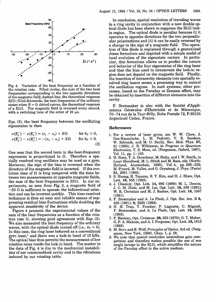
Fig. 4. Variation of the bethe rotation rate. Filled cifrequencies corresponding tof the magnetic field; dashec25qf: filled diamonds. the be
In conclusion, spatial resolution of traveling wavesin a ring cavity in conjunction with a new double op-
- a, tical diode has been shown to suppress the RLG lock-in region. The optical diode is peculiar because (i) it
-,,' operates in opposite directions for the two perpendic-, ' .. - ular polarizations and (ii) it can be easily reversed by
___________________ tio.-a change in the sign of a magnetic field. The opera-20 a c e intion of this diode is explained through a generalized
0 10 20 30 Jones formalism and depicted with a simple model oflocal evolution of the eigenstate vectors. In partic-
Q ( O. s-'l) ular, this formalism allows us to predict the natureand behavior of the four eigenstates of the ring laserand that the bias used to circumvent the lock-in re-gion does not depend on the magnetic field. Finally,the insertion of intracavity elements into spatially re-
~at frequency as a function of solved ring lasers seems a promising way to control
rcles, the sum of the two beat the oscillation regime. In such systems, other pro-to the two opposite directions cesses, based on the Faraday or Zeeman effect, mayI line, the theoretical response be obtained by insertion of different elements into thetat frequencies of the ordinary cavity.
states when B = 0; dotted curves, the theoretical responseof a RLG. The magnetic field is reversed every second,with a switching time of the order of 10 jus.
Eqs. (2), the beat frequency between the oscillatingeigenstates is then
One sees that the second term in the beat-frequencyexpression is proportional to fQ. Therefore a spa-tially resolved ring oscillator may be used as a gyro.Moreover, the sign of the bias is reversed when thedirection of the magnetic field is inverted. If the evo-lution time of f1 is long compared with the time be-tween two measurements at opposite magnetic fields,the sum of the beat frequencies is 2Sf. In our ex-periments, as seen from Fig. 3, a magnetic field of-30 G is sufficient to operate the bidirectional selec-tion and can be inverted quickly. This time-resolvedtechnique is thus an easy and reliable means of sup-pressing residual bias fluctuations while doubling theapparent sensitivity of the device.
Figure 4 presents the experimental values of thesum of the beat frequencies as a function of the rota-tion rate fQ, showing good agreement with Eqs. (3).We also measured the beat frequency of the ordinarywaves, with the optical diode turned off (i.e., OF = 0).In this case, the ring laser behaved as a conventionalgyro laser,1 and there was a lock-in band of 15 kHz.The optical bias thus permits the measurement of lowrotation rates inside the lock-in band. The scatter inthe data of Fig. 4 is due to the mechanical instabili-ties of our nonmonoblock cavity and to the vibrationsinduced by our rotating table.
F. Bretenaker is also with the Soci6t6 d'Appli-cations G6n6rales d'Electricit6 et de M6canique,70-74 rue de la Tour-Billy, Boite Postale 72, F-95101Argenteuil Cedex, France.
References
1. For a review of laser gyros, see W. W. Chow, J.Gea-Banacloche, L. M. Pedrotti, V. E. Sanders,W. Schleich, and M. 0. Scully, Rev. Mod. Phys. 57,61 (1985); J. R. Wilkinson, in Progress in QuantumElectronics, T. S. Moss, ed. (Pergamon, Oxford, 1987),Vol. 11, pp. 1-103.
2. H. Statz, T. A. Dorschner, M. Holtz, and I. W. Smith, inLaser Handbook, M. L. Stitch and M. Bass, eds. (North-Holland, Amsterdam, 1985), Vol. 4, pp. 229-332;M. Pinard, M. Vallet, and G. Grynberg, J. Phys. (Paris)51, 2091 (1990).
3. S. Huang, K. Toyama, B. Y. Kim, and H. J. Shaw, Opt.Lett. 18, 555 (1993).
4. J. Chesnoy, Opt. Lett. 14, 990 (1989); M. L. Dennis,J. C. M. Diels, and M. Lai, Opt. Lett. 16, 529 (1991);W. R. Christian and M. J. Rosker, Opt. Lett. 16, 1587(1991).
5. F. Bretenaker and A. Le Floch, J. Opt. Soc. Am. B 8,230 (1991); 9, 2295 (1992).
6. N. H. Tran, T. Foucher, P. Lagoutte, C. Migault,F. Bretenaker, and A. Le Floch, Opt. Lett. 18, 2056(1993).
7. F. Biraben, Opt. Commun. 29,353 (1979); G. T. Maker,G. P. A. Malcom, and A. I. Ferguson, Opt. Lett. 18, 1813(1993).
8. M. Born and E. Wolf, Principles of Optics, 3rd ed. (Perg-amon, New York, 1986), Chap. 1, p. 38.
9. We note that spatial resolution neutralizes gain com-petition and therefore makes possible the use of onesingle isotope in the RLG, which simplifies the natureof the Faraday effect in the active medium.