10
Data Sheet Earth Leakage Relay Record Analyze Control Measure A 8.8 8 8 ... RISH ELR VI K EL A V RL-1 RL-2 Digital Protection Relay RESET TEST ENTER RISH ELR/ELR+/ELR VI/ELR VI(NE)
Data SheetEarth Leakage Relay
Record AnalyzeControlMeasure
A 8.8 8 8. . .
RISH ELR VI
K
EL
A
V
RL-1 RL-2
Digital Protection Relay
RESET TEST ENTER
RISH ELR/ELR+/ELR VI/ELR VI(NE)
Data SheetEarth Leakage Relay
Record AnalyzeControlMeasure
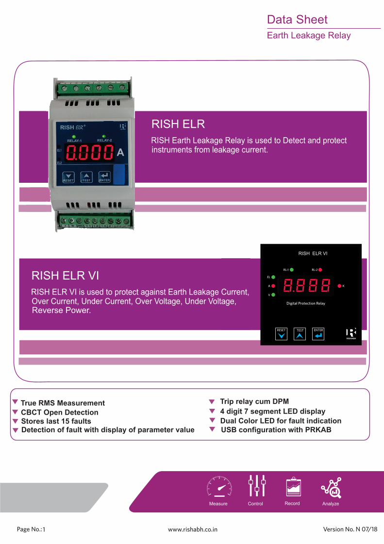
True RMS Measurement
Stores last 15 faults Detection of fault with display of parameter value USB configuration with PRKAB
4 digit 7 segment LED displayCBCT Open Detection
Trip relay cum DPM
RISH ELR
RISH Earth Leakage Relay is used to Detect and protect instruments from leakage current.
Dual Color LED for fault indication
RISH ELR VI
RISH ELR VI is used to protect against Earth Leakage Current, Over Current, Under Current, Over Voltage, Under Voltage, Reverse Power.
A
8.8 8 8. . .
RISH ELR VI
K
EL
A
V
RL-1 RL-2
Digital Protection Relay
RESET TEST ENTER
1 N 07/18

8.8 8 8. . .
RISH ELR VI
K
EL
A
V
RL-1 RL-2
Digital Protection Relay
RESET TEST ENTER
LED indication
- LED indication for relay-1, relay-2 status.
- Trip indication are displayed on 4 Digit display.
Protection for Control panels and switch boards.
Protection for Sensitive environment like chemical plants,
Earth Leakage Protection for Generators, Feeders, utility
Applications:
Leakage current monitoring in 1 & 3 phase system
Auto re-closure / Manual reset
In auto re-closure mode instrument automatically tries to
If the fault persists it disconnects the load. If device set into manual mode, then device must be
Previous fault storage
User selectable trip setting
Compliance to International Safety standardsCompliance to International Safety standard
IEC 61010 - 1 - 2010
Product Features:
.
Protection for Mining and control Engineering.
EMC Compatibility
Compliance to International standard IEC 61326
Trip relay cum DPM
re-connect load within a programmable specified time.
Programmable trip setting from 30mA to 30A
reset manually by push button.
4 digits ultra bright LED display
User selectable password protection
Test and reset key on front Panel display.
Device Configuration with PRKAB Simply con gure the RISH ELR using PRKAB interface.
Instrument memorizes the last 15 faults occurred.
A single ELR+ can Protect two different Loads at a time
Multi Load Protection:
with two CBCT input.
CBCT Open Detection
- LED indication EL for one CBCT model, EL1, EL2 for two CBCT model and V (Voltage), I (Current) and
Inverse Curve for higher Earth Leakage current protection.
power monitoring, Transformers, Motor
Oil refiners.
True RMS measurement
The instrument measures distorted waveform up to 15Harmonic.
th
Adjustable set point & set delay for
-Pre alarm
-Over Voltage
-Under Voltage -Over Current
-Under Current
-Leakage Current
-Reverse Power
Reverse Power Protection (3P4W balanced load,
Over Voltage Protection
Under Voltage Protection
Over Current Protection
Under Current Protection
3P3W balanced load, 1P2W)
Earth to Neutral voltage measurement and
Protection in RISH ELR VI (NE) model.
k for ELR VI Model.
Model Available with measurement and Protection of
Multi Parameter Protection:
Multiple parameters like Voltage, Current and Leakage current of load in a single Device i.e ELR -VI.
Data SheetEarth Leakage Relay
Record AnalyzeControlMeasure
2 N 07/18

Technical Specifications:Input
Auxiliary Supply:
Higher Aux 60 V – 300V AC-DC ----------------------------------------------------------------------------------------------------------------
Aux supply frequency 45 to 66 Hz range
Reference condition for Accuracy :
Reference Condition 23°C +/- 2°C----------------------------------------------------------------------------------------------------------------Input waveform Sinusoidal (distortion factor 0.005)----------------------------------------------------------------------------------------------------------------Input Frequency 50 or 60 Hz ±2%----------------------------------------------------------------------------------------------------------------Auxiliary supply voltage 230 VAC / DC ±1%----------------------------------------------------------------------------------------------------------------Auxiliary supply frequency 50 or 60 Hz ±1%
Nominal Input Voltage (AC RMS) 5 V AC (for Earth to Neutral Voltage measure-ment), 500 (V AC).
Max Continuous Input Voltage(OL Indication)
127% of PT Secondary
System PT Secondary range 1V to 5 VAC, 50V to 500 V programmable on site (as per resp. model).
System PT Primary range 50 to 1200 kV programmable on site. (Note: - Not applicable for 1 to 5V AC input).
Nominal Input Current (AC RMS) 5 A
Max Continuous Input Current(OL Indication)
145% of CT Secondary
System CT Secondary Values 1 A to 5 A programmable on site
System CT Primary Values 1A to 999 kA programmable on site
Operating Frequency Range 45 to 66 Hz
----------------------------------------------------------------------------------------------------------------
----------------------------------------------------------------------------------------------------------------
----------------------------------------------------------------------------------------------------------------
----------------------------------------------------------------------------------------------------------------
----------------------------------------------------------------------------------------------------------------
----------------------------------------------------------------------------------------------------------------
----------------------------------------------------------------------------------------------------------------
----------------------------------------------------------------------------------------------------------------
ELR - VI model
Lower Aux 20-60VDC / 20-40 VAC ----------------------------------------------------------------------------------------------------------------
----------------------------------------------------------------------------------------------------------------Leakage current (I n) 30 mA to 30A
Tripping Range 80% to 100% of I n
Accuracy :
---------------------------------------------------------------------------------------------------------------Trip, Pre Alarm time delays ± 5% of Set Delay or ± 50 msec.
---------------------------------------------------------------------------------------------------------------Instantaneous tripping <25msec for leakage current greater than
(for Leakage Current) (whichever is greater).
Voltage ± 1% of nominal value
Input Current ± 1% of nominal value---------------------------------------------------------------------------------------------------------------
Power ON ,Reset, Trip (for Voltage ± 5% of Set Delay or ± 140 msec.
(whichever is greater).
---------------------------------------------------------------------------------------------------------------
Leakage Current ± 5% of Full Scale---------------------------------------------------------------------------------------------------------------
(Applicable for Leakage tripping) 5 X I n
& Current) time delays
Power ± 2% of nominal value---------------------------------------------------------------------------------------------------------------
----------------------------------------------------------------------------------------------------------------Input Voltage Range 50% to 125% of Pt Secondary----------------------------------------------------------------------------------------------------------------Input Current Range 20% to 140% of Ct Secondary
L N
L N
1 2 7 8 9
L
N
Aux Supply
NC
L
O
A
D
3 4
S1 S2
S1 S2
CBCT
5 6
RISH ELR-VI
NC NC
7 8 9
L
N
Aux Supply
NC
L
O
A
D
1 2
S1 S2
CBCT1
5 6
RISH ELR+
S1 S2
CBCT2
3 4
L
O
A
D
L
N
7 8 9
L
N
L N
Aux Supply
NC
L
O
A
D
1 2
S1 S2
CBCT
5 6
RISH ELR
NC NC
3 4
NC NC
L N
1 2 7 8 9
L
N
NC
L
O
A
D
3 4
S1 S2
S1 S2
CBCT
5 6
RISH ELR - VI (For Earth to Neutral Voltage Measurement)
E
E
E
E
E
EL1
Current Voltage
Aux Supply
EL1
Current Voltage
EL1
EL 2
EL1
A) DIN RAIL MOUNTABLE ELR:
Electrical Connection:
11
12 14
Relay 1 Relay 2
21
22 24
COM
NC NO
COM
NC NO
Relay Terminals for All Models
Data SheetEarth Leakage Relay
Record AnalyzeControlMeasure
3 N 07/18

L N
6 8 9 10 7
L
N
Aux Supply
NC
L
O
A
D
3 4
S1 S2
S1 S2
CBCT
1 2
RISH ELR-VI
L
N
O
A
D
S1 S2
CBCT1
1 2
RISH ELR+
S1 S2
CBCT2
3 4
L
O
A
D
L
N
L
N
O
A
D
3 4
S1 S2
CBCT
1 2
RISH ELR
NC NC
L N
6 8 9 10 7
L
N
NC
L
O
A
D
3 4
S1 S2
S1 S2
CBCT
1 2
RISH ELR - VI (For Earth to Neutral Voltage Measurement)
E
E
E
E
E
EL1
Current Voltage
Aux Supply
EL1
Current Voltage
EL1
EL 2
EL1
9 10
L N
Aux Supply L
5 6
NC NC
7 8
NC NC
9 10
L N
Aux Supply L
5 6
NC NC
7 8
NC NC
A) PANEL MOUNTABLE ELR:
Electrical Connection:
Applicable Standards:
EMC IEC 61326-1:2012, Table 2---------------------------------------------------------------------------------------------------------------Immunity IEC 61000-4-3. 10V/m min – Level 3
---------------------------------------------------------------------------------------------------------------Safety use IEC 61010-1-2010 , Permanently connected ---------------------------------------------------------------------------------------------------------------IP for water & dust IEC 60529---------------------------------------------------------------------------------------------------------------Pollution degree: 2---------------------------------------------------------------------------------------------------------------Installation category: 300 V CAT III / 600 V CAT II---------------------------------------------------------------------------------------------------------------High Voltage Test 2.2 KV AC, 50Hz for 1 minute between all
Environmental:
Operating temperature -10 to + 55°C---------------------------------------------------------------------------------------------------------------Storage temperature -25 to + 70°C---------------------------------------------------------------------------------------------------------------Relative humidity 0... 95% non condensing---------------------------------------------------------------------------------------------------------------Shock 15g in 3 planes---------------------------------------------------------------------------------------------------------------Vibration 10... 55 Hz, 0.15mm amplitude---------------------------------------------------------------------------------------------------------------
Enclosure IP20 (front face only)
Relay Contacts:
Types of output 1CO, 2CO, 1CO+1CO---------------------------------------------------------------------------------------------------------------Contact Ratings (Res. Load) 5A/250VAC/30VDC---------------------------------------------------------------------------------------------------------------Mechanical Endurance 1x10^7 OPS
Electrical Endurance NO- 3x10^4 OPS
Different Load Type CBCT connection Diagram:
Maximum Cable Length for connection between Meter and CBCT : <1 Mtr
Note: - Use Twisted pair shielded cable. (Not to be run parallel to power cables).
Testing as per IEC 60947- 2, Annex - M ---------------------------------------------------------------------------------------------------------------
Weight < 300g Aprrox
Mechanical Attributes:
VA Burden
Input current burden < 0.25 VA approx. per phase
Auxiliary supply burden < 4 VA approx for AC aux.
LOAD
R
Y
B
N
S1 S2
CBCT
E
3 Phase 3 wire connection
LOAD
R
Y
B
S1 S2
CBCT
E
3 Phase 4 wire connection
Input voltage burden < 0.6 VA approx.
Data SheetEarth Leakage Relay
Record AnalyzeControlMeasure
---------------------------------------------------------------------------------------------------------------
4 N 07/18
92m
m+
0.8
Panel Cutout
92mm+0.8
35 mm
27 mm
6 mm
Side View
96m
mDisplay Area
96 mm
Front View
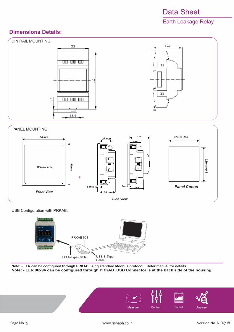
Dimensions Details:
Note: - ELR can be configured through PRKAB using standard Modbus protocol. Refer manual for details.
#
DIN RAIL MOUNTING:
PANEL MOUNTING:
USB B-Type Cable
PRKAB 601
USB A-Type Cable
USB Configuration with PRKAB:
Note: - ELR 96x96 can be configured through PRKAB .USB Connector is at the back side of the housing.
Data SheetEarth Leakage Relay
Record AnalyzeControlMeasure
5 N 07/18
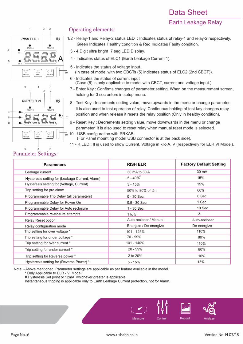
9 - Reset Key : Decrements setting value, move downwards in the menu or change
parameter. It is also used to reset relay when manual reset mode is selected.
Parameters RISH ELR
Hysteresis setting for (Leakage Current, Alarm) 5 - 40%
Energize / De-energize
Programmable Trip Delay (all parameters)
Programmable Delay for Power On
Programmable Delay for Auto reclosure
Relay Reset option
Leakage current 30 mA to 30 A
0.5 - 30 Sec
0 - 30 Sec
Parameter Settings:
A
RISH ELR +
k
RELAY-1 RELAY-2
RISHABH
ENTERTESTRESET
RISHABH
3 - 4 Digit ultra bright 7 seg LED Display.
8 - Test Key : Increments setting value, move upwards in the menu or change parameter.
It is also used to test operation of relay. Continuous holding of test key changes relay
position and when release it resets the relay position (Only in healthy condition).
1 3 2
10
8 79
Operating elements:
1/2 - Relay-1 and Relay-2 status LED : Indicates status of relay-1 and relay-2 respectively.
7 - Enter Key : Confirms changes of parameter setting. When on the measurement screen,
holding for 3 sec enters in setup menu.
Relay configuration mode
Auto-recloser / Manual
10 - USB configuration with PRKAB (For Panel mounting model USB connector is at the back side).
1 - 30 Sec
4
5 4 - Indicates status of ELC1 (Earth Leakage Current 1).
5 - Indicates the status of voltage input.
6 - Indicates the status of current input
EL 1
(In case of model with two CBCTs (5) indicates status of ELC2 (2nd CBCT)).
(Case (6) is only applicable to model with CBCT, current and voltage input.)
Programmable re-closure attempts 1 to 5
Trip setting for over voltage *
Trip setting for under voltage *
101 - 125%
70 - 99%
Trip setting for over current * 101 - 140%
Trip setting for under current * 20 - 99%
Note: - Above mentioned Parameter settings are applicable as per feature available in the model. * Only Applicable to ELR - VI Model. # Hysteresis Set point or 12mA whichever greater is applicable. Instantaneous tripping is applicable only to Earth Leakage Current protection, not for Alarm.
Green Indicates Healthy condition & Red Indicates Faulty condition.
Factory Default Setting
RISH ELR VI
k
RELAY-1 RELAY-2
RISHABH
ENTERTESTRESET
RISHABH
1 3 2
10
8 79
V
A
4
6
5
EL
k 11
11 - K LED : It is used to show Current, Voltage in kilo A, V (respectively for ELR VI Model).
30 mA
15%
0 Sec
60%
1 Sec
3
10 Sec
Auto-recloser
De-energize
110%
80%
EL 2
Hysteresis setting for (Voltage, Current) 3 - 15% 15%
Trip setting for pre alarm 50% to 80% of I n
#
110%
80%
Trip setting for Reverse power * 2 to 20% 10%
Hysteresis setting for (Reverse Power) * 5 - 15% 15%
Data SheetEarth Leakage Relay
Record AnalyzeControlMeasure
6 N 07/18

ELR Ordering Information:
Model Name Description
RISH ELR
RISH ELR +
RISH ELR VI
RISH ELR with single CBCT input
RISH ELR with two CBCT inputs
RISH ELR with CBCT, current and voltage input(one each)
Auxiliary supply voltage
60 - 300V AC DC
20 - 60V DC / 20 - 40V AC
HA
LA
Model Name
RISH ELR
RISH ELR +
RISH ELR VI
1 CO 1 CO + 1CO 2 CO
4000 4001
4011
4021
4002
Description
2] RISH ELR+ - 4011 - LA -96:-
RISH ELR+, 1CO + 1CO, lower auxiliary supply Panel Mount 96X96.
× ×
× ×
: Not Applicable ×Note: - No need to specify secondary current as it is programmable from 1A to 5A for ELR - VI model.
RISH ELR VI (NE) can be used for Earth to Neutral Voltage measurement (Voltage Measurement range is 1 to 5 VAC).
ELR Order Code Example:
RISH ELR VI (NE) 4031 × ×
Inverse Curve Formula: Relay Operating Time = Set Trip Delay XTrip Set value
Measured value
Example: -A) For “OV” (Over Voltage) PT Secondary = 100 VTrip point = 105% of PT Secondary = 105 VHysteresis = 3% of PT Secondary = 3 VRelay Reset point = Trip point - Hysteresis = 105 - 3 = 102 V
Hysteresis Calculation Method:
Example: -B) For Leakage Current Leakage Current setting = 10 ATripping point = 80% to 100% of set Leakage Current = 8 - 10 AHysteresis = 10% of set Leakage Current = 1 ARelay Reset point = Tripping point - Hysteresis = 8 - 1 = 7 A
Size
Panel mount 96X96 96
Description
DIN Rail Mount TS35
Data SheetEarth Leakage Relay
Record AnalyzeControlMeasure
7 N 07/18

Core Balance Current Transformer (CBCT):-
> RISH TWE - 73/30(50)
> RISH TWE - 95/50(40)
> RISH TWE - 135/85(30)
> RISH TWE - 165/130(30)
Features: - > Slim Design
Models : -
> Encapsulated CBCT
> Compact in size
> Light in Weight
CBCT Specifications: - CBCT Type : Closed Toroid
Turns Ratio : 600 / 1A
Rated Current : 30A
System Voltage : 720 V maximum
Insulation Voltage : 3kV for 1 minute
System Frequency : 50 Hz or 60 Hz
Distance Between CBCT and ELR : < 1 meters
Operating Temperature : -10°C to +55°C
RISH TWE - 73/30(50)
RISH TWE - 95/50(40)
RISH TWE - 135/85(30)
RISH TWE - 165/130(30)
CBCT Ordering Information:
CBCT 73
CBCT 95
CBCT 135
CBCT 165
CBCT Description
RISH TWE - 73/30(50)
RISH TWE - 95/50(40)
RISH TWE - 135/85(30)
RISH TWE - 165/130(30)
1] RISH -2 :- CBCT 73
RISH . CBCT TWE - 73/30(50), Quantity Two
CBCT Order Code Example:
2] RISH -1 :- CBCT 165
RISH One. CBCT TWE - 165/130(30), Quantity
RISH TWE - 260/200(22)
Dimensions :-
OD
ID
Axial
CBCT IDOD Axial
RISH TWE - 73/30(50)
RISH TWE - 95/50(40)
RISH TWE - 135/85(30)
RISH TWE - 165/130(30)
73
95
135
165
30
50
85
130
50
40
30
30
Diamentions (in mm)
Current Ranges
30mA to 30A
30mA to 30A
30mA to 30A
500mA to 30A
W
L
H
W
CBCT HL W
RISH TWE - 260/200(22) 260 200 22
Current Ranges
30mA to 30A
> RISH TWE - 260/200(22)
CBCT 260 RISH TWE - 260/200(22)
Data SheetEarth Leakage Relay
Record AnalyzeControlMeasure
8 N 07/18

Record AnalyzeControlMeasure


