RISK ASSESSMENT FOR CO2 GEOLOGICAL SEQUESTRATION Yan Zhang Department of Chemical Engineering Carnegie Mellon University Panagiotis Vouzis Department of Chemical Engineering Carnegie Mellon University Nick Sahinidis National Energy Technology Laboratory Department of Chemical Engineering Carnegie Mellon University [email protected]
Transcript
RISK ASSESSMENT FOR CO2 GEOLOGICAL SEQUESTRATION
Yan Zhang Department of Chemical Engineering
Carnegie Mellon University
Panagiotis Vouzis Department of Chemical Engineering
Carnegie Mellon University
Nick Sahinidis National Energy Technology Laboratory
Department of Chemical Engineering Carnegie Mellon University
• Introduction to CO2 sequestration • A sequestration simulator • Risk assessment work • GPU parallel computing • Conclusions and future work
2�
INTRODUCTION TO CO2 SEQUESTRATION
• Effect of anthropogenic CO2 on global warming • Carbon mitigation portfolio
– Improved efficiency vehicles – Decarbonization
• renewable, nuclear
– Sequestration
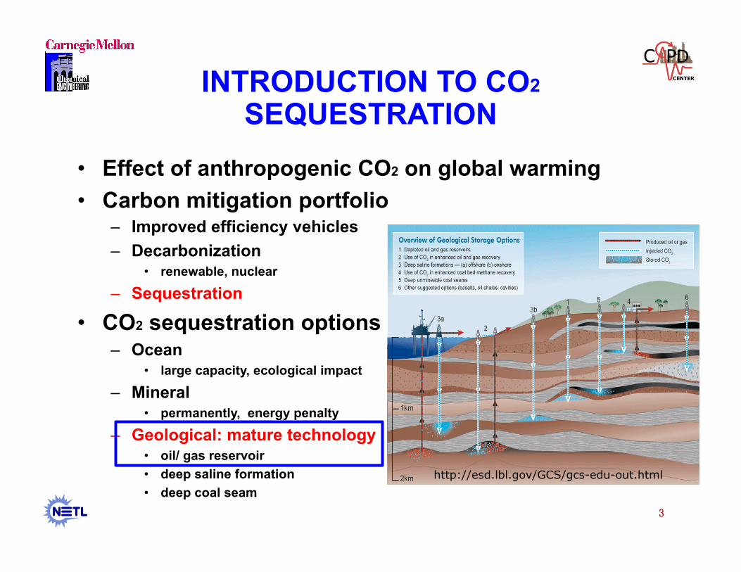
• CO2 sequestration options – Ocean
• large capacity, ecological impact
– Mineral • permanently, energy penalty
– Geological: mature technology • oil/ gas reservoir • deep saline formation • deep coal seam
3�
http://esd.lbl.gov/GCS/gcs-edu-out.html
REVIEW OF SEQUESTRATION MODELING
• Assess the feasibility of CO2 sequestration • Models for
– Pre-injection estimation: capacity evaluation, injection rate, etc – Post-injection prediction: evolution of the sequestration system
4�
Reference Model Modeled problems Formation Trapping mechanism
Bickle et al., 2007 analytical Calibration of model to seismic monitoring data from the Sleipner injection site in the North Sea
homogeneous
Bromhal et., 2005 numerical : PSU-COALCOMP
Storage with enhanced coal-bed methane recovery homogeneous sorption
Doughty and Pruess, 2004
Numerical: TOUGH2
Simulated injection at Frio, TX, test site, evaluated effects of numerical artifacts, choice of characteristic curves
Stochastic three-dimensional heterogeneous
Capillary trapping dissolution
Fiett et al., 2007 Numerical CHEARS
Injection into saline aquifer, assessed impact of varying heterogeneity(sand/shale ratio) on migration
Stochastic three-dimensional heterogeneous
Dissolution, capillary trapping
Gaus et al., 2005 Numerical
Considered impact of geochemical reactions induced by CO2 injection on caprock integrity, based on the Sleipner site
Layered heterogeneity Dissolution, mineralization
*: G.Schnaar and D. C. Digiulio, Vadose Zone Journal, 2009
*
REVIEW OF SEQUESTRATION MODELING (CONT’D)
5�
Reference Model Modeled problems Formation Trapping mechanism
Gheraidi et al., 2005
Numerical: TOUGHREACT
Assessed impact of mineral precipitation and dissolution reactions on migration through caprock; sensitivity analysis for initial mineralogy, kinetic parameters, caprock permeability
Layered heterogeneity Dissolution, mineralization
Izgec et al., 2005 Numerical: STARS
Calibrated model of mineral precipitation and decrease in permeability to data from core experiments; sensitivity analysis for mineralization rate parameters
Homogeneous Dissolution, mineralization
Jessen et al., 2005 Numerical:ECLIPSE300
Injection with enhanced oil recovery operation, analyzed different operation strategies for maximizing storage
Injection in formation similar to North Sea; sensitivity analysis for permeability; assessed leakage through penetration; migration under non-flat caprock
Nordbotten et al., 2004, 2005a, 2005b, 2006a, 2006b
Analytical Analytical solutions for CO2 leakage through abandoned wells Homogeneous
Oldenburg et al., 2001
Numerical: TOUGH2
Injection into formation based on Rio Vista gas field in California for sequestration and enhanced natural gas recovery
Homogeneous
*: G.Schnaar and D. C. Digiulio, Vadose Zone Journal, 2009
*
CQUESTRA
• IEA GHG Weyburn CO2 Monitoring & Storage Project
• Address the migration and fate of CO2 by quantifying – The leakage rate of CO2 to the biosphere – The spatial extent of CO2 plumes underground
• Starts from the end of EOR phase
7�
Figures from Whittaker et al., 2004
REVIEW OF RISK ASSESSMENT WORK
• What is the risk associated with sequestration?
• Models are used for quantitative risk analysis to predict CO2 movement in response to varying conditions or scenarios – Walton et al., 2005, used probabilistic risk assessment to
understand and evaluate the performance of CO2 geological sequestration.
– Raza et al., 2009, performed uncertainty analysis using Monte Carlo simulation for capacity estimates and leakage potential for a saline aquifer.
8�
PHYSICAL SYSTEM
9�
>800
Approx. Depth (m) 300
Radius ~0.1m
Aquifer 1 Aquifer 2
Aquifer 4
Aquifer 3
Aquifer 5
Aquifer 6
Aquitard 2
Aquitard 4
Aquitard 3
Aquitard 5 Aquitard 6
Biosphere
Upper Formations
Lower Formations
Oil Reservoir
CO2 Source Pool
Simplified geological structure
Annulus cement
Steel casing
Cement plug
Caprock Low permeability
PROCESS DESCRIPTION
10�
• Viability of a sequestration system:
Leakage
vs .
Sequestration
M: CO2 mass Fi: inflow rate = 0 Fo: outflow rate = leakage-sequestration
Failed seals of wellbore
Open fractures and faults
Dissolution of source pool
Mineralization & geological trapping
Migration of CO2 into surrounding formations
Wellbore
Caprock
Celia et al., 2004
LEAKAGE THROUGH WELLBORE
• Non-penetrating well equation
11�
Wellbore
Caprock
CO2 movement
Fluid pressure
Buoyancy CO2 source pool
MOVEMENT THROUGH CAPROCK
• Equation for drainage in tunnels
12�
Wellbore
Caprock
Fluid pressure
Buoyancy CO2 source pool
DISSOLUTION OF SOURCE POOL
• Dissolution of source pool to the formations below or above the source
13�
CO2 source pool
A layer of stagnant formation fluids
CO2 source pool
A layer of moving formation fluids
Diffusion through a semi-infinite plane
Diffusion through a falling film
Steady state dissolution rate =
Diffusion through a semi-infinite plane
+
Diffusion through a falling film
MIGRATION THROUGH FAILED SEALS
• Migration of CO2 to surrounding formations through failed seals on the way of rising up – Failure times are unpredictable
• If the cement annulus fails first… • If the cement plug fails first…
– Physical model Heat conduction from a thin wire
• Aquifer with advection, dispersion and reaction • Aquitard with diffusion and reaction
Apply solution for temperature profile
Get CO2 concentration in the formation
Obtain steady state flux at the wall of the wellbore
Migration rate = steady state flux * concentration at the wall * thickness 14�
OVERALL MASS BALANCE
• The mass left in the reservoir pool as time goes by:
15�
M0 is the initial mass of the CO2 source pool; FD is the flow rate by diffusion from pool; λ is the first order rate constant for mineralization; Nw is the number of wellbores intercepting the pool; NF is the number of fractures in the caprock; ρw is the density of water; ρs is the density of the CO2 phase; Ks is the hydraulic conductivity of the reservoir; KF is the hydraulic conductivity of the fracture; φs is the average head gradient; φF is the head gradient at the fracture; εs is the porosity of the reservoir; Ss is the fractional saturation of CO2 in source pool; rb is the radius of wellbore; h0 is the initial height of the source pool; wF is the width of the fracture; As is the area of the source pool; Co is the solubility of CO2 ; D is the free diffusion coefficient; and τ is the tortuosity factor.
Depends on the failure times of wellbore components
MODEL PARAMETERS
• Parameters: – Main independent parameters
– Main calculated parameters: formation fluid density, free phase density, viscosity, solubility, etc.