24
Risk Assessment: Onshore Oil and Gas Exploration and Appraisal in RJ-ONHP-2017/2 Block, Barmer and Jalore District, Rajasthan Vedanta Limited. (Division Cairn Oil & Gas)
Risk Assessment: Onshore Oil and Gas Exploration and Appraisal in RJ-ONHP-2017/2 Block, Barmer and Jalore District, Rajasthan
Vedanta Limited. (Division Cairn Oil & Gas)
Vedanta Limited. (Division CAIRN Oil & Gas) Final EIA: Onshore Oil and Gas E&A in RJ-ONHP- 2017/2 Block, Barmer District, Rajasthan
July 2019 AECOM
2
1.1. Risk Assessment The objective of the RA study is to identify major risk contributing events, demarcate vulnerable zones and evaluate
the nature of risk posed to nearby areas due to proposed drilling activity, in addition to ensure compliance to
statutory rules and regulations. The scope of work for the study is described below :
• Identify potential risk scenarios that may arise from the proposed drilling and other associated activities
• Analyze the possible likelihood and frequency of such risk scenarios by reviewing historical accident related
data.
• Predict the consequences of such potential risk scenarios and if consequences are high, establish the same
by through application of quantitative simulations.
• Recommend feasible preventive and risk mitigation measures as well as provide inputs for drawing up of
Emergency Response Plan (ERP) for the project.
• The assessments to be based on various existing documents including Emergency Response Plan (ERP),
Disaster Management Plan (DMP).
1.1.1. Quantitative Risk Assessment Risk” is defined as the combination of the expected frequency and consequence of accidents that could occur as
a result of an activity. Risk assessment is a formal process of increasing one understands of the risk associated
with an activity. The process of risk assessment includes answering three questions:
• What can go wrong?
• How likely is it?
• What are the impacts?
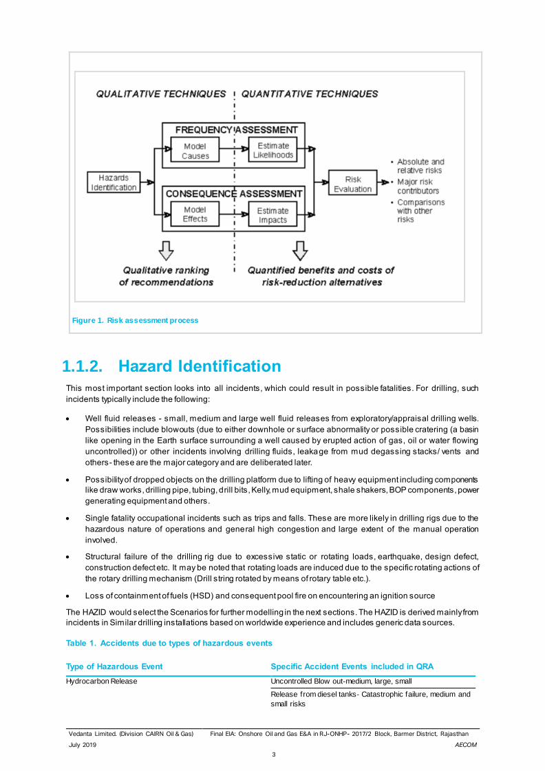
Qualitative answers to one or more of these questions are often sufficient for making good decisions about the
allocation of resources for safety improvements. But, as managers seek quantitative cost/benefit information upon
which to base their decisions, they increasingly turn their attention to the use of QRA. Figure 16 depicts the overall
RA process.
QRA is the art and science of developing and understanding numerical estimates of the risk (i .e., combinations of
the expected frequency and consequences of potential accidents) associated with a facility or operation. It uses a
set of highly sophisticated, but approximate tools for acquiring risk understanding. The Overall approach for the
Risk Assessment in brief has been given here with details in the further chapters.
The various steps in the QRA process are described below.
• Hazard Identification
• Consequence Analysis
• Initial Failure Frequency assessment
• Construction of Event Trees
• Calculation of Average Individual Risk
• Risk Assessment and preparation of Risk reduction recommendations
Vedanta Limited. (Division CAIRN Oil & Gas) Final EIA: Onshore Oil and Gas E&A in RJ-ONHP- 2017/2 Block, Barmer District, Rajasthan
July 2019 AECOM
3
Figure 1. Risk assessment process
1.1.2. Hazard Identification This most important section looks into all incidents, which could result in possible fatalities. For drilling, such
incidents typically include the following:
• Well fluid releases - small, medium and large well fluid releases from exploratory/appraisal drilling wells.
Possibilities include blowouts (due to either downhole or surface abnormality or possible cratering (a basin
like opening in the Earth surface surrounding a well caused by erupted action of gas, oil or water flowing
uncontrolled)) or other incidents involving drilling fluids, leakage from mud degassing stacks/ vents and
others- these are the major category and are deliberated later.
• Possibility of dropped objects on the drilling platform due to lifting of heavy equipment including components
like draw works, drilling pipe, tubing, drill bits, Kelly, mud equipment, shale shakers, BOP components, power
generating equipment and others.
• Single fatality occupational incidents such as trips and falls. These are more likely in drilling rigs due to the
hazardous nature of operations and general high congestion and large extent of the manual operation
involved.
• Structural failure of the drilling rig due to excessive static or rotating loads, earthquake, design defect,
construction defect etc. It may be noted that rotating loads are induced due to the specific rotating actions of
the rotary drilling mechanism (Drill string rotated by means of rotary table etc.).
• Loss of containment of fuels (HSD) and consequent pool fire on encountering an ignition source
The HAZID would select the Scenarios for further modelling in the next sections. The HAZID is derived mainly from
incidents in Similar drilling installations based on worldwide experience and includes generic data sources.
Table 1. Accidents due to types of hazardous events
Type of Hazardous Event Specific Accident Events included in QRA
Hydrocarbon Release Uncontrolled Blow out-medium, large, small
Release from diesel tanks- Catastrophic failure, medium and
small risks
Vedanta Limited. (Division CAIRN Oil & Gas) Final EIA: Onshore Oil and Gas E&A in RJ-ONHP- 2017/2 Block, Barmer District, Rajasthan
July 2019 AECOM
4
Source: Vedanta Ltd. (Division Cairn Oil & Gas)
1.1.3. Hydrocarbon Release The events of blowouts during drilling are divided in the databases according to the consequences and well control
success. Such blow outs can be ignited or un-ignited. Blow outs are uncontrolled sudden expulsions of oil, gas,
water or drilling fluids from wells to the surface which result in loss of control of the well.
Sources of hydrocarbon release during the drilling phase include the following:
• Dissolved gas which comes out of solution under reduced pressure often while dril ling at near balance or
under balance hydrostatically or as trip gas during a round trip to pull the drill string around from the hole.
Such sources could include releases at bell nipple and around mud return flow line outlet, shale shakers and
active mud pits.
• As a “kick”, which occurs as the down hole formation pressure unexpectedly exceeds the hydrostatic head of
the circulating mud column. Significant releases can occur from the vent lines of the mud /gas separator and
other locations.
• From residual mud on the surface of the drill pipe being racked in the derrick during the round trip, or on
production of coil tubing being withdrawn from the hole, or from core samples laid out for inspection. Usually
any liquid hydrocarbon system entering the down hole under normal circumstances are very much diluted by
the mud system. However, under conditions of under balanced drilling, the proportion of hydrocarbons in mud
returns may be significant with a potential for continuous release.
• Small hydrocarbon release from rotating equipment, pipes and pump work occurring during normal
operations/ maintenance during drilling. These are not likely to be significant in open derrick or mast
structures.
• Possible shallow gas blowout – these may occur at sumps or drainage tanks and be conveyed by vents or
drains to areas of potential ignition sources resulting in fire/ explosion.
• Vapour present in oily drainage systems, vents, and ducting.
• Flammable materials used in drilling operations (oil-based drilling fluids)- release points could include high
pressure mud points, mud degassing equipment, shale shaker, mud pits and active tanks etc.
1.1.4. Protection against Blowouts The primary protections against blow outs during drilling are the BOPs or Blow out Preventers. These are used to
shut in and control the well in the event of gas or oil being encountered at pressures higher than those exerted by
the column of mud in the hole.
BOPs typically consist of 2-3 ram preventers designed at high pressures- (ram preventer is basically a double
operated valve with one ram or gate on each side of the bore hole). The BOPs are hydraulically operated with a
second remote control panel situated someway away from the rig for use in emergencies when the rig is
unapproachable. Connected to the side of the ram type preventers (usually below the blind rams) are the kill and
choke lines which are used to control the well in the event of any imba lance between the drilling fluid column
pressure and the formation pressure. Both lines are high pressure 2-3-inch hydraulic pipes, the kill line being
connected to the mud circulation system and the high-pressure cement pumps and the choke line leading to a
back-pressure control Manifold and the mud degasser unit.
In the event of the high-pressure kick with the drill string in the hole, the BOP is closed around the drill pipe and
the mud is circulated down the drill string and back to the mud tanks through the choke line and back pressure
manifold. The manifold consists of a series of valves and chokes - the choke can be adjusted to give the orifice
opening required such as to give a back pressure on the well in order to control it. There would be two chokes in
order to allow maintenance on one.
Occupational accidents Single fatality accidents such as slips, trips, falls, dropped
objectives etc.
Structural failure Structural collapse of drilling rig due to static or rotating load,
fatigue, construction defect, design defect, earthquakes etc
Vedanta Limited. (Division CAIRN Oil & Gas) Final EIA: Onshore Oil and Gas E&A in RJ-ONHP- 2017/2 Block, Barmer District, Rajasthan
July 2019 AECOM
5
If a kick or blow out occurs with the drill string out of the hole, the blind rams are closed, and heavy mud is pumped
into the well through the kill line. Any gas can be bled off through the choke line and fluids are usually squeezed
back into the formation.
The correct installation of the drilling equipment and the operational reliability of the BOPs are essential for the
safety of well drilling operation. In addition, initial and periodic testing of the BOPs, ch oke and kill manifolds, high
pressure/ heavy mud system etc. before installation and periodically is absolutely essential. Most important is the
presence of highly trained skilled personnel on the rig! In addition, the use of the correct drilling fluid in the
circulatory system is extremely vital.
• The drilling fluid basically does the following:
• To cool and lubricate the drilling bit and the drill string
• To remove drill solids and allowing the release at their surface.
• To form a gel to suspend the drill cuttings and any fluid material when the column is static
• To control sub surface pressures
• To prevent squeezing and caving if formations
• To plaster the sides of the borehole
• To minimize the damage to any potential production zone.
Pressures associated with the sub surface oil, gas or water can be controlled by increasing the specific gravity of
the fluid and thereby by reducing the hydrostatic head of the drilling fluid column. The squeezing of formations in
the drilled hole can be checked by increasing the hydrostatic head of the drilling fluid. Special additives for the
drilling fluid for controlling viscosity, lubricating properties, gelling properties etc. play an important role in the drill ing
fluid integrity. Sealing agents such as cellulose, mica can also be added to make up the drilling fluid loss into the
porous and fractured formations.
The historical records show that the drilling of an exploration well has a higher chance of blow out occurring than
does drilling a development well. A blow out can be expected for about 400 exploration wells drilled. As a well takes
about 20-25 days to drill this equates to one blow out approximately every 50 years if drilling was continuous.
Historically, ignited blowouts have caused an average of three deaths per blow out.
1.1.5. Release of the other flammable material HSD is used in the mobile generators at the drill sites to cater to the power requirement of the drill equipment, area
lighting, etc. The material will be stored in 180 MT vertical cylindrical tank. Spill containment system in the form of
1.2m high bund wall is envisaged to contain 110% of the tank volume. Storage of fuels would primarily pose fire
hazard. The credible accident scenarios include:
• Catastrophic tank rupture (Large Leak)
• Leak from a 4” pipeline (Medium Leak)
• A 2” leak from the tank/pipe/flange (Small Leak)
The catastrophic Rupture (CR) of the tank would involve a large leak/big hole in the tank or disengagement of a
joint/large leak from a flange sufficient enough to discharge tank inventory in a short time. The spilled material shall
get filled into the dyke area. In presence of an ignition source, it may catch fire and result in Pool fire of the dyke
area.
A 4” leak from a pipeline or a flange shall have similar consequences as to CR, only the time for loss of containment
may be more. Fire being a surface phenomenon, the pool fire in the dyke area would pose similar heat radiation to
the surrounding area.
A 2” leak from the tank or the pipeline would result in the loss of inventory at a much-reduced rate. Counter-
measures shall be available to arrest the leak within reasonable time. With a limited loss of inventory, the damage
distances in such case would be less in comparison to the above two cases.
The tank design and construction takes into account the possible stress loads imposed due to exploration and
appraisal activities at the drill site. Dyke with adequate capacity (110%) is being provided to contain the spill, if any.
Standard well area inspection and maintenance procedures of CIL shall be implemented at the exploratory and
appraisal wells to identify any abnormalities.
Vedanta Limited. (Division CAIRN Oil & Gas) Final EIA: Onshore Oil and Gas E&A in RJ-ONHP- 2017/2 Block, Barmer District, Rajasthan
July 2019 AECOM
6
1.2. CONSEQUENCE ANALYSIS/CALCULATIONS Consequence analysis involves the calculation of the initial “release rate” and then predicting the consequence of
the release through computer modeling- it forms an important ingredient in the QRA approach. Consequence
analysis is a complex procedure involving numerous calculations. It must also be noted that a single starting
incident could have numerous outcomes depending upon factors such as escalation, ignition and others.
The various factors of importance in this drilling rig study with respect to consequence analysis are described
below.
1.2.1. Loss of Containment- leak sizes It must be understood that there are an infinite range of possible releases of flammable material on the facilities
For example, a hole could appear at any point in a well, at any time of the year and the hole could have any size
(right from pinhole to catastrophic line guillotine rupture) and also possibly any shape! In order to allow management
of the study, it is per force necessary to divide the infinite range into a number of small er ranges through
representation as a single event or a failure case.
In the study, only small, medium and large well fluid blowouts were considered.
Hydrocarbon Leaks due to Loss of Containment (Leak during Well Testing) were not taken into consideration since
they are likely to be controlled about 95% of the time. The category includes releases that may be isolated from
the reservoir fluids, typically release from the well testing equipment and mud line.
1.2.2. Inventory Inventory can get discharged to Environment due to Loss of Containment. Inventory Analysis is commonly used in
understanding the relative hazards and short listing of release scenarios and plays an important role in regard to
the potential hazard. The larger the inventory of a vessel or a “system”, the larger the quantity of potential release.
The potential release depends upon the quantity of release, the properties of the materials and the operating
conditions (pressure, temperature etc. described later).
1.2.3. Blowouts A blowout on the topsides may take one of several forms and release locations. Any release not immediately ignited
would give a flammable vapour cloud, which could cause a vapour cloud explosion in the drill floor or the mud pit
areas.
A pressurized jet release could lead to a very large jet fire, producing high levels of thermal radiation. The flame
could impinge on structural members in the derrick. These could then fail as they lose their mechanical properties
at high temperature. This may lead to objects falling from the derrick and causing more damage below, especially
if the derrick has already been weakened by the blast from a vapour cloud explosion. If the fire continues for a long
period (say one to two hours) then the derrick may collapse causing serious damage to surrounding areas.
However, evacuation is expected to have occurred by any available means before this time.
This scenario is a worst-case scenario, which is unlikely to happen in this situation as the bottom hole pressure is
low.
Unburnt oil from a potential blowout will typically form running or evaporating pools, which could create a hazard
from heat and smoke in all areas that the pools reach. If the blow out originates on the drill floor then the burning
oil will run over the side of the drill floor.
1.2.4. Consequence Analysis for Blowouts Blowout release rate is taken as 0.12 kg/s assuming 5 times the normal rate from the well. It is expected that the
uncontrolled release of fluids on the drill floor will ignite almost immediately and that the resulting fire will eng ulf the
drill floor. Higher ignition probabilities are expected for large releases compared to smaller releases. The flames
are likely to impinge on structural members on the drill floor. These may fail as they lose their mechanical properties
at high temperature. This may lead to objects falling from the derrick and causing more damage below. If the fire
continues for a long period.
Vedanta Limited. (Division CAIRN Oil & Gas) Final EIA: Onshore Oil and Gas E&A in RJ-ONHP- 2017/2 Block, Barmer District, Rajasthan
July 2019 AECOM
7
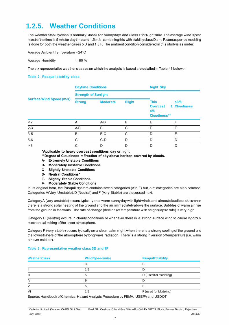
1.2.5. Weather Conditions The weather stability class is normally Class D on sunny days and Class F for Night time. The average wind speed
most of the time is 5 m/s for day time and 1.5 m/s. combining this with stability class D and F, consequence modeling
is done for both the weather cases 5 D and 1.5 F. The ambient condition considered in this study is as under:
Average Ambient Temperature = 24˚C
Average Humidity = 80 %
The six representative weather classes on which the analysis is based are detailed in Table 48 below: -
Table 2. Pasqual stability class
*Applicable to heavy overcast conditions day or night
**Degree of Cloudiness = Fraction of sky above horizon covered by clouds.
A- Extremely Unstable Conditions
B- Moderately Unstable Conditions
C- Slightly Unstable Conditions
D- Neutral Conditions*
E- Slightly Stable Conditions
F- Moderately Stable Conditions
In its original form, the Pasquill system contains seven categories (A to F) but joint categories are also common.
Categories A (Very Unstable), D (Neutral) and F (Very Stable) are discussed next.
Category A (very unstable) occurs typically on a warm sunny day with light winds and almost cloudless skies when
there is a strong solar heating of the ground and the air immediately above the surface. Bubbles of warm air rise
from the ground in thermals. The rate of change (decline) of temperature with height (lapse rate) is very high.
Category D (neutral) occurs in cloudy conditions or whenever there is a strong surface wind to cause vigorous
mechanical mixing of the lower atmosphere.
Category F (very stable) occurs typically on a clear, calm night when there is a strong cooling of the ground and
the lowest layers of the atmosphere by long wave radiation. There is a strong inversion of temperature (i.e. warm
air over cold air).
Table 3. Representative weather class 5D and 1F
Source: Handbook of Chemical Hazard Analysis Procedure by FEMA, USEPA and USDOT
Surface Wind Speed (m/s)
Daytime Conditions Night Sky
Strength of Sunlight
Strong Moderate Slight Thin
Overcast ≥
4/8
Cloudiness**
≤3/8
Cloudiness
< 2 A A-B B E F
2-3 A-B B C E F
3-5 B B-C C D E
5-6 C C-D D D D
> 6 C D D D D
Weather Class Wind Speed(m/s) Pasquill Stability
I 3 B
II 1.5 D
III 5 D (used for modeling)
IV 9 D
V 5 E
VI 1.5 F (used for Modeling)
Vedanta Limited. (Division CAIRN Oil & Gas) Final EIA: Onshore Oil and Gas E&A in RJ-ONHP- 2017/2 Block, Barmer District, Rajasthan
July 2019 AECOM
8
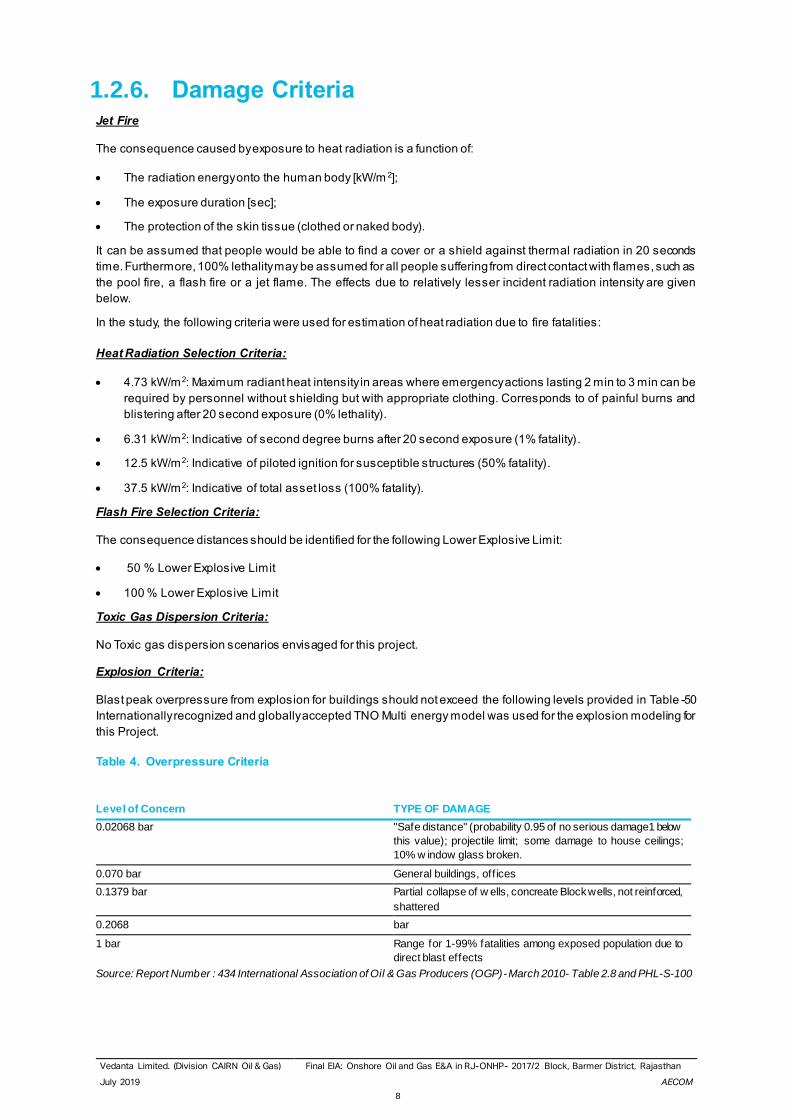
1.2.6. Damage Criteria Jet Fire
The consequence caused by exposure to heat radiation is a function of:
• The radiation energy onto the human body [kW/m 2];
• The exposure duration [sec];
• The protection of the skin tissue (clothed or naked body).
It can be assumed that people would be able to find a cover or a shield against thermal radiation in 20 seconds
time. Furthermore, 100% lethality may be assumed for all people suffering from direct contact with flames, such as
the pool fire, a flash fire or a jet flame. The effects due to relatively lesser incident radiation intensity are given
below.
In the study, the following criteria were used for estimation of heat radiation due to fire fatalities:
Heat Radiation Selection Criteria:
• 4.73 kW/m2: Maximum radiant heat intensity in areas where emergency actions lasting 2 min to 3 min can be
required by personnel without shielding but with appropriate clothing. Corresponds to of painful burns and
blistering after 20 second exposure (0% lethality).
• 6.31 kW/m2: Indicative of second degree burns after 20 second exposure (1% fatality).
• 12.5 kW/m2: Indicative of piloted ignition for susceptible structures (50% fatality).
• 37.5 kW/m2: Indicative of total asset loss (100% fatality).
Flash Fire Selection Criteria:
The consequence distances should be identified for the following Lower Explosive Limit:
• 50 % Lower Explosive Limit
• 100 % Lower Explosive Limit
Toxic Gas Dispersion Criteria:
No Toxic gas dispersion scenarios envisaged for this project.
Explosion Criteria:
Blast peak overpressure from explosion for buildings should not exceed the following levels provided in Table -50
Internationally recognized and globally accepted TNO Multi energy model was used for the explosion modeling for
this Project.
Table 4. Overpressure Criteria
Level of Concern TYPE OF DAMAGE
0.02068 bar "Safe distance" (probability 0.95 of no serious damage1 below
this value); projectile limit; some damage to house ceilings;
10% w indow glass broken.
0.070 bar General buildings, off ices
0.1379 bar Partial collapse of w ells, concreate Block wells, not reinforced,
shattered
0.2068 bar
1 bar Range for 1-99% fatalities among exposed population due to
direct blast effects
Source: Report Number : 434 International Association of Oil & Gas Producers (OGP)- March 2010- Table 2.8 and PHL-S-100
Vedanta Limited. (Division CAIRN Oil & Gas) Final EIA: Onshore Oil and Gas E&A in RJ-ONHP- 2017/2 Block, Barmer District, Rajasthan
July 2019 AECOM
9
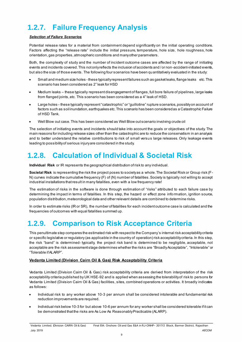
1.2.7. Failure Frequency Analysis Selection of Failure Scenarios
Potential release rates for a material from containment depend significantly on the initial operating conditions.
Factors affecting the “release rate” include the initial pressure, temperature, hole size, hole roughness, hole
orientation, gas properties, atmospheric conditions and many other parameters.
Both, the complexity of study and the number of incident outcome cases are affected by the range of initiating
events and incidents covered. This not only reflects the inclusion of accidents and / or non -accident-initiated events,
but also the size of those events. The following four scenarios have been quantitatively evaluated in the study:
• Small and medium size holes - these typically represent failures such as gasket leaks, flange leaks etc. This
scenario has been considered as 2” leak for HSD
• Medium leaks – these typically represent disengagement of flanges, full bore failure of pipelines, large leaks
from flanged joints, etc. This scenario has been considered as a 4” leak of HSD.
• Large holes– these typically represent “catastrophic” or “guillotine” rupture scenarios, possibly on account of
factors such as soil inundation, earthquakes etc. This scenario has been considered as a Catastrophic Failure
of HSD Tank.
• Well Blow out case. This has been considered as Well Blow out scenario involving crude oil
The selection of initiating events and incidents should take into account the goals or objectives of the study. The
main reasons for including release sizes other than the catastrophic are to reduce the conservatism in an analysis
and to better understand the relative contributions to risk of small versus large releases. Only leakage events
leading to possibility of serious injury are considered in the study.
1.2.8. Calculation of Individual & Societal Risk Individual Risk or IR represents the geographical distribution of risk to any individual.
Societal Risk is representing the risk the project poses to society as a whole. The Societal Risk or Group risk (F-
N) curves indicate the cumulative frequency (F) of (N) number of fatalities. Society is typically not willing to accept
industrial installations that result in many fatalities, even with a low frequency rate!
The estimation of risks in the software is done through estimation of “risks” attributed to each failure case by
determining the impact in terms of fatalities. In this step, the hazard or effect zone info rmation, ignition source,
population distribution, meteorological data and other relevant details are combined to determine risks.
In order to estimate risks (IR or SR), the number of fatalities for each incident outcome case is calculated and the
frequencies of outcomes with equal fatalities summed up.
1.2.9. Comparison to Risk Acceptance Criteria This penultimate step compares the estimated risk with respect to the Company’s internal risk acceptability criteria
or specific legislative or regulatory (as applicable in the country of operation) risk acceptability criteria. In this step,
the risk “band” is determined- typically, the project risk band is determined to be negligible, acceptable, not
acceptable are the risk assessment stage determines whether the risks are “Broadly Acceptable”, “Intolerable” or
“Tolerable if ALARP”.
Vedanta Limited (Division Cairn Oil & Gas) Risk Acceptability Criteria
Vedanta Limited (Division Cairn Oil & Gas) risk acceptability criteria are derived from interpretation of the risk
acceptability criteria published by UK HSE-92 and is applied when assessing the tolerability of risk to persons for
Vedanta Limited (Division Cairn Oil & Gas) facilities, sites, combined operations or activities. It broadly indicates
as follows:
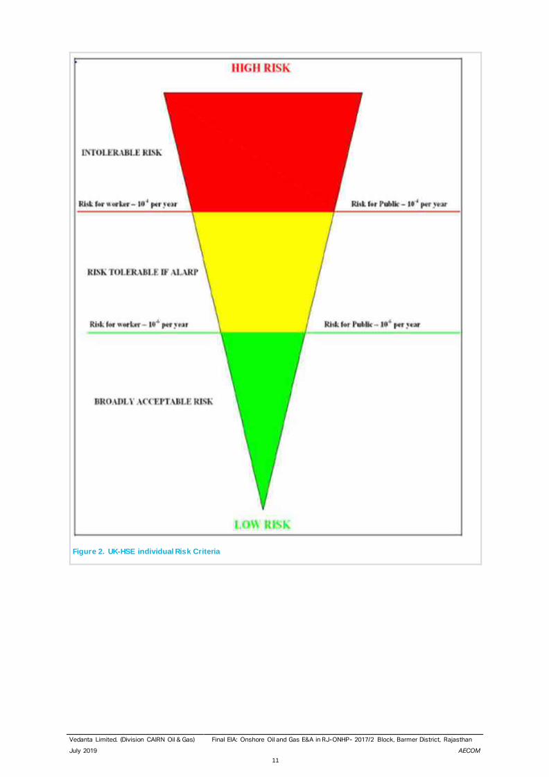
• Individual risk to any worker above 10-3 per annum shall be considered intolerable and fundamental risk
reduction improvements are required.
• Individual risk below 10-3 for but above 10-6 per annum for any worker shall be considered tolerable if it can
be demonstrated that the risks are As Low As Reasonably Practicable (ALARP).

Vedanta Limited. (Division CAIRN Oil & Gas) Final EIA: Onshore Oil and Gas E&A in RJ-ONHP- 2017/2 Block, Barmer District, Rajasthan
July 2019 AECOM
10
• Individual risk below 10-6 per annum for any worker shall be considered as broadly acceptable and no further
improvements are considered necessary provided documented control measures are in place and
maintained.
• Individual risk to any member of the general public as a result of Vedanta Limited (Division Cairn Oil & Gas)
Businesses activities shall be considered as intolerable if greater than10-4 per annum, broadly acceptable if
less than 10-6 per annum and shall be reduced to As Low As Reasonably Practicable (ALARP) between these
limits.
• For new facilities, Vedanta Limited (Division Cairn Oil & Gas) shall strive to achieve lower risks compared with
that typical for existing facilities, down at least to an individual risk to any worker of 10-4 per annum, by the
appropriate use of best practice including technology and management techniques.
• For existing facilities, higher risk levels may be tolerated provided that they are As Low As Reasonably
Practicable (ALARP) and meet the minimum standards given herein. As facilities under Vedanta Limited
(Division Cairn Oil & Gas) expansion may be considered as “new” facilities; it is proposed that individual risk
to any worker above 10-4 per annum shall be considered intolerable.
The risk acceptability criteria are indicated in the following pages.
Vedanta Limited. (Division CAIRN Oil & Gas) Final EIA: Onshore Oil and Gas E&A in RJ-ONHP- 2017/2 Block, Barmer District, Rajasthan
July 2019 AECOM
11
Figure 2. UK-HSE individual Risk Criteria
Vedanta Limited. (Division CAIRN Oil & Gas) Final EIA: Onshore Oil and Gas E&A in RJ-ONHP- 2017/2 Block, Barmer District, Rajasthan
July 2019 AECOM
12
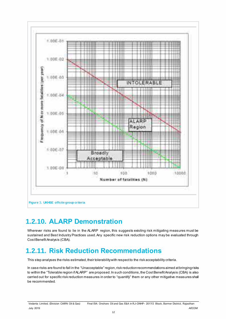
Figure 3. UKHSE offsite group criteria
1.2.10. ALARP Demonstration Wherever risks are found to lie in the ALARP region, this suggests existing risk mitigating measures must be
sustained and Best Industry Practices used. Any specific new risk reduction options may be evaluated through
Cost Benefit Analysis (CBA).
1.2.11. Risk Reduction Recommendations This step analyses the risks estimated, their tolerability with respect to the risk acceptability criteria.
In case risks are found to fall in the “Unacceptable” region, risk reduction recommendations aimed at bringing risks
to within the “Tolerable region if ALARP” are proposed. In such conditions, the Cost Benefit Analysis (CBA) is also
carried out for specific risk reduction measures in order to “quantify” them or any other mitigative measures shall
be recommended.
Vedanta Limited. (Division CAIRN Oil & Gas) Final EIA: Onshore Oil and Gas E&A in RJ-ONHP- 2017/2 Block, Barmer District, Rajasthan
July 2019 AECOM
13
In case risks have been found to be the ALARP or Broadly Acceptable region, recommendations may still be
suggested for generic risk reduction based on industry best practice. Such risk reduction recommendations are not
“quantified” or mandatory but are nevertheless proposed for safer operation of the facilities.
1.2.12. Software Used The Software, DNV PHAST was used for the study for assessing the Risk and Consequence calculations.
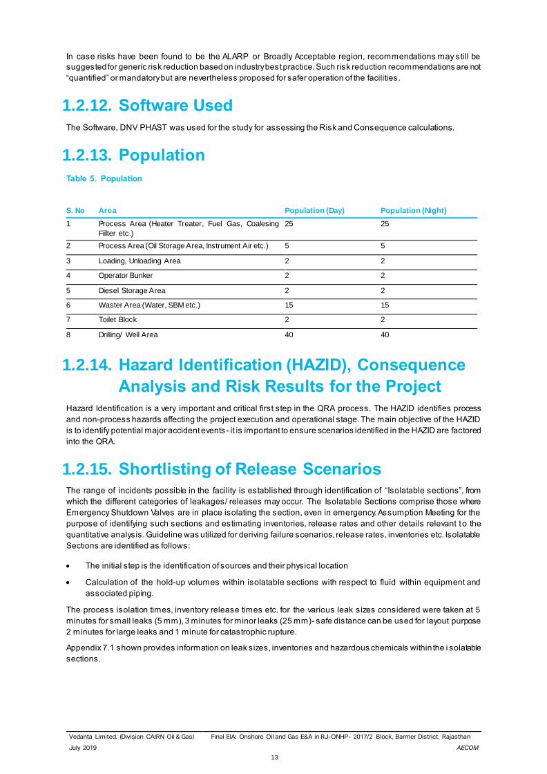
1.2.13. Population
Table 5. Population
S. No Area Population (Day) Population (Night)
1 Process Area (Heater Treater, Fuel Gas, Coalesing
Fiilter etc.)
25 25
2 Process Area (Oil Storage Area, Instrument Air etc.) 5 5
3 Loading, Unloading Area 2 2
4 Operator Bunker 2 2
5 Diesel Storage Area 2 2
6 Waster Area (Water, SBM etc.) 15 15
7 Toilet Block 2 2
8 Drilling/ Well Area 40 40
1.2.14. Hazard Identification (HAZID), Consequence
Analysis and Risk Results for the Project Hazard Identification is a very important and critical first step in the QRA process. The HAZID identifies process
and non-process hazards affecting the project execution and operational stage. The main objective of the HAZID
is to identify potential major accident events - it is important to ensure scenarios identified in the HAZID are factored
into the QRA.
1.2.15. Shortlisting of Release Scenarios The range of incidents possible in the facility is established through identification of “Isolatable sections”, from
which the different categories of leakages/ releases may occur. The Isolatable Sections comprise those where
Emergency Shutdown Valves are in place isolating the section, even in emergency. Assumption Meeting for the
purpose of identifying such sections and estimating inventories, release rates and other details relevant to the
quantitative analysis. Guideline was utilized for deriving failure scenarios, release rates, inventories etc. Isolatable
Sections are identified as follows:
• The initial step is the identification of sources and their physical location
• Calculation of the hold-up volumes within isolatable sections with respect to fluid within equipment and
associated piping.
The process isolation times, inventory release times etc. for the various leak sizes considered were taken at 5
minutes for small leaks (5 mm), 3 minutes for minor leaks (25 mm)- safe distance can be used for layout purpose
2 minutes for large leaks and 1 minute for catastrophic rupture.
Appendix 7.1 shown provides information on leak sizes, inventories and hazardous chemicals within the i solatable
sections.
Vedanta Limited. (Division CAIRN Oil & Gas) Final EIA: Onshore Oil and Gas E&A in RJ-ONHP- 2017/2 Block, Barmer District, Rajasthan
July 2019 AECOM
14
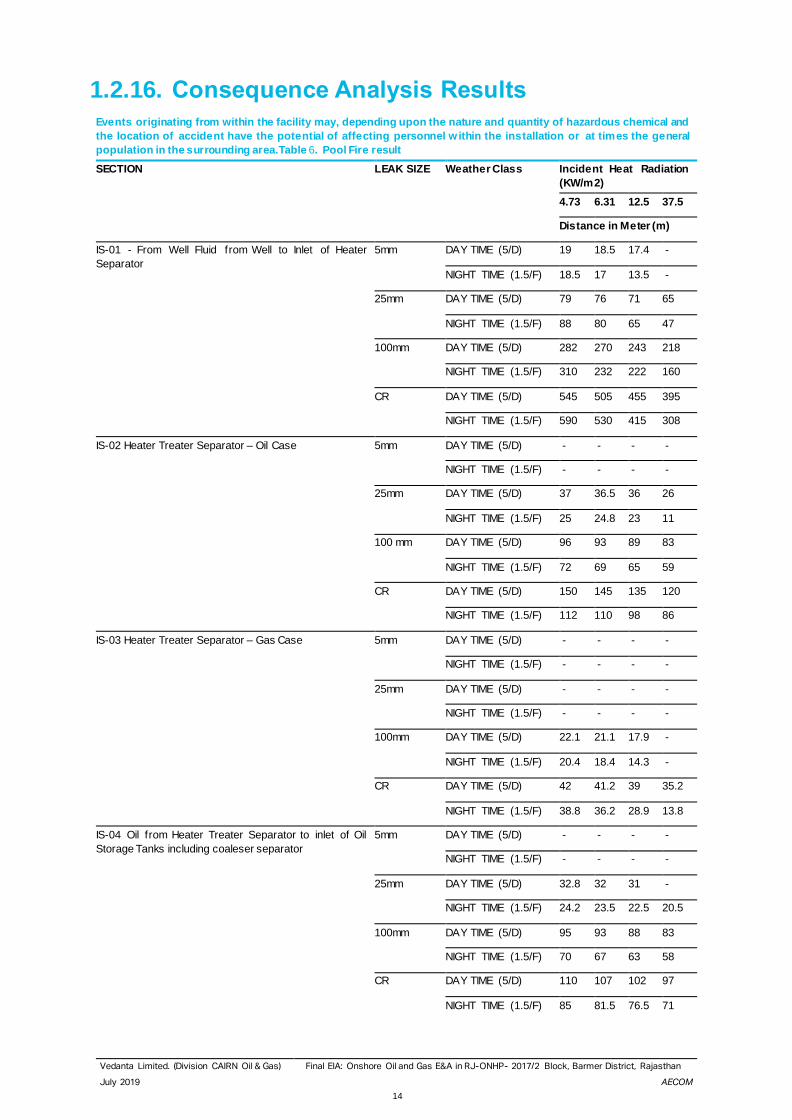
1.2.16. Consequence Analysis Results Events originating from within the facility may, depending upon the nature and quantity of hazardous chemical and
the location of accident have the potential of affecting personnel w ithin the installation or at times the general
population in the surrounding area.Table 6. Pool Fire result
SECTION LEAK SIZE Weather Class Incident Heat Radiation
(KW/m2)
4.73 6.31 12.5 37.5
Distance in Meter (m)
IS-01 - From Well Fluid from Well to Inlet of Heater
Separator
5mm DAY TIME (5/D) 19 18.5 17.4 -
NIGHT TIME (1.5/F) 18.5 17 13.5 -
25mm DAY TIME (5/D) 79 76 71 65
NIGHT TIME (1.5/F) 88 80 65 47
100mm DAY TIME (5/D) 282 270 243 218
NIGHT TIME (1.5/F) 310 232 222 160
CR DAY TIME (5/D) 545 505 455 395
NIGHT TIME (1.5/F) 590 530 415 308
IS-02 Heater Treater Separator – Oil Case 5mm DAY TIME (5/D) - - - -
NIGHT TIME (1.5/F) - - - -
25mm DAY TIME (5/D) 37 36.5 36 26
NIGHT TIME (1.5/F) 25 24.8 23 11
100 mm DAY TIME (5/D) 96 93 89 83
NIGHT TIME (1.5/F) 72 69 65 59
CR DAY TIME (5/D) 150 145 135 120
NIGHT TIME (1.5/F) 112 110 98 86
IS-03 Heater Treater Separator – Gas Case 5mm DAY TIME (5/D) - - - -
NIGHT TIME (1.5/F) - - - -
25mm DAY TIME (5/D) - - - -
NIGHT TIME (1.5/F) - - - -
100mm DAY TIME (5/D) 22.1 21.1 17.9 -
NIGHT TIME (1.5/F) 20.4 18.4 14.3 -
CR DAY TIME (5/D) 42 41.2 39 35.2
NIGHT TIME (1.5/F) 38.8 36.2 28.9 13.8
IS-04 Oil from Heater Treater Separator to inlet of Oil
Storage Tanks including coaleser separator
5mm DAY TIME (5/D) - - - -
NIGHT TIME (1.5/F) - - - -
25mm DAY TIME (5/D) 32.8 32 31 -
NIGHT TIME (1.5/F) 24.2 23.5 22.5 20.5
100mm DAY TIME (5/D) 95 93 88 83
NIGHT TIME (1.5/F) 70 67 63 58
CR DAY TIME (5/D) 110 107 102 97
NIGHT TIME (1.5/F) 85 81.5 76.5 71
Vedanta Limited. (Division CAIRN Oil & Gas) Final EIA: Onshore Oil and Gas E&A in RJ-ONHP- 2017/2 Block, Barmer District, Rajasthan
July 2019 AECOM
15
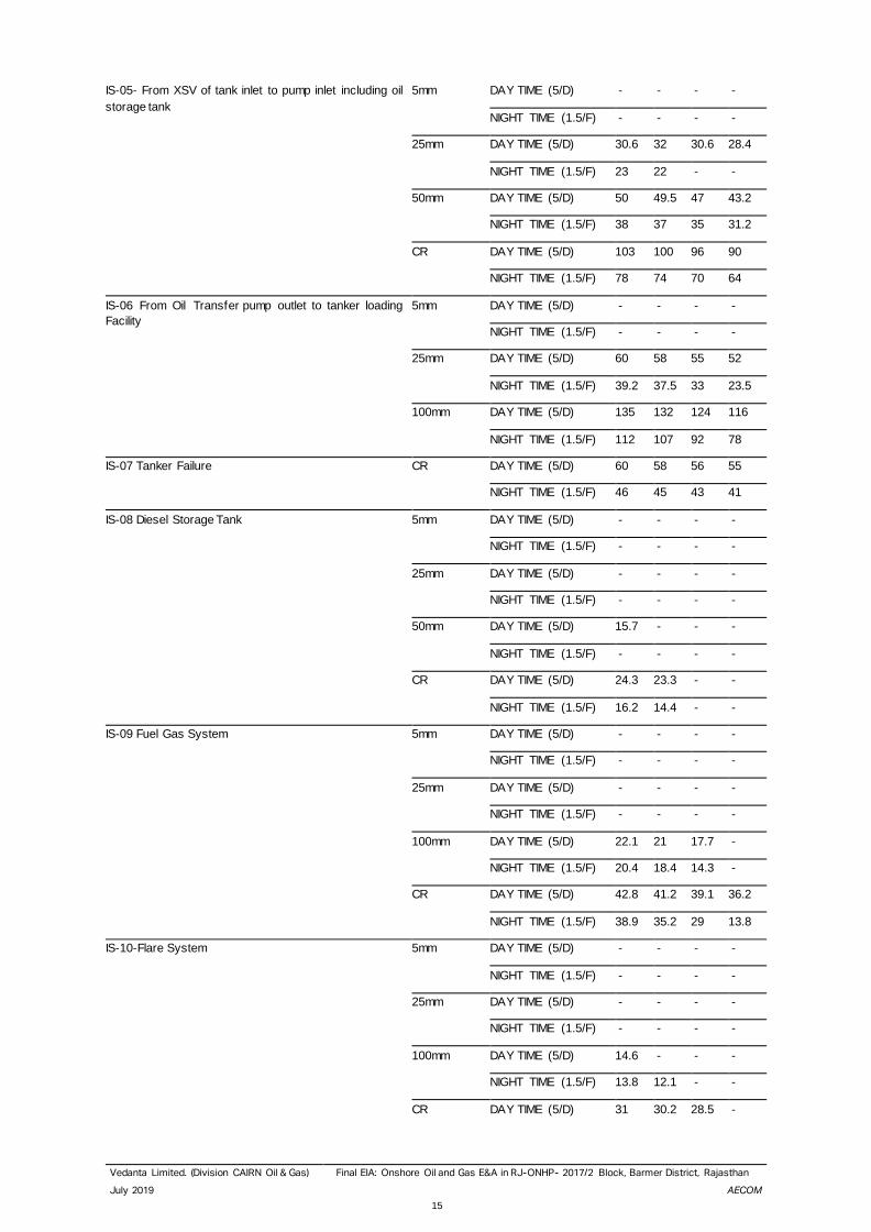
IS-05- From XSV of tank inlet to pump inlet including oil
storage tank
5mm DAY TIME (5/D) - - - -
NIGHT TIME (1.5/F) - - - -
25mm DAY TIME (5/D) 30.6 32 30.6 28.4
NIGHT TIME (1.5/F) 23 22 - -
50mm DAY TIME (5/D) 50 49.5 47 43.2
NIGHT TIME (1.5/F) 38 37 35 31.2
CR DAY TIME (5/D) 103 100 96 90
NIGHT TIME (1.5/F) 78 74 70 64
IS-06 From Oil Transfer pump outlet to tanker loading
Facility
5mm DAY TIME (5/D) - - - -
NIGHT TIME (1.5/F) - - - -
25mm DAY TIME (5/D) 60 58 55 52
NIGHT TIME (1.5/F) 39.2 37.5 33 23.5
100mm DAY TIME (5/D) 135 132 124 116
NIGHT TIME (1.5/F) 112 107 92 78
IS-07 Tanker Failure CR DAY TIME (5/D) 60 58 56 55
NIGHT TIME (1.5/F) 46 45 43 41
IS-08 Diesel Storage Tank 5mm DAY TIME (5/D) - - - -
NIGHT TIME (1.5/F) - - - -
25mm DAY TIME (5/D) - - - -
NIGHT TIME (1.5/F) - - - -
50mm DAY TIME (5/D) 15.7 - - -
NIGHT TIME (1.5/F) - - - -
CR DAY TIME (5/D) 24.3 23.3 - -
NIGHT TIME (1.5/F) 16.2 14.4 - -
IS-09 Fuel Gas System 5mm DAY TIME (5/D) - - - -
NIGHT TIME (1.5/F) - - - -
25mm DAY TIME (5/D) - - - -
NIGHT TIME (1.5/F) - - - -
100mm DAY TIME (5/D) 22.1 21 17.7 -
NIGHT TIME (1.5/F) 20.4 18.4 14.3 -
CR DAY TIME (5/D) 42.8 41.2 39.1 36.2
NIGHT TIME (1.5/F) 38.9 35.2 29 13.8
IS-10-Flare System 5mm DAY TIME (5/D) - - - -
NIGHT TIME (1.5/F) - - - -
25mm DAY TIME (5/D) - - - -
NIGHT TIME (1.5/F) - - - -
100mm DAY TIME (5/D) 14.6 - - -
NIGHT TIME (1.5/F) 13.8 12.1 - -
CR DAY TIME (5/D) 31 30.2 28.5 -
Vedanta Limited. (Division CAIRN Oil & Gas) Final EIA: Onshore Oil and Gas E&A in RJ-ONHP- 2017/2 Block, Barmer District, Rajasthan
July 2019 AECOM
16
NIGHT TIME (1.5/F) 29 26.5 21 -
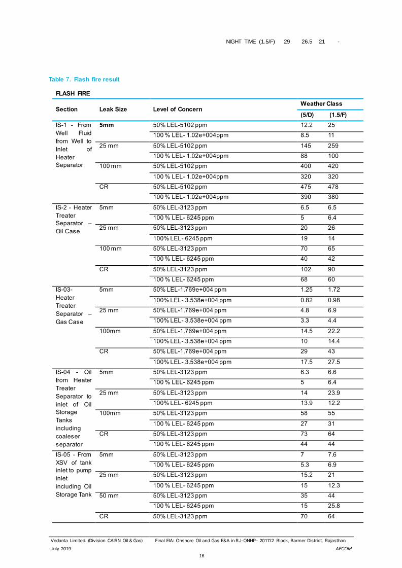
Table 7. Flash fire result
FLASH FIRE
Section Leak Size Level of Concern Weather Class
(5/D) (1.5/F)
IS-1 - From
Well Fluid
from Well to
Inlet of
Heater
Separator
5mm 50% LEL-5102 ppm 12.2 25
100 % LEL- 1.02e+004ppm 8.5 11
25 mm 50% LEL-5102 ppm 145 259
100 % LEL- 1.02e+004ppm 88 100
100 mm 50% LEL-5102 ppm 400 420
100 % LEL- 1.02e+004ppm 320 320
CR 50% LEL-5102 ppm 475 478
100 % LEL- 1.02e+004ppm 390 380
IS-2 - Heater
Treater
Separator –
Oil Case
5mm 50% LEL-3123 ppm 6.5 6.5
100 % LEL- 6245 ppm 5 6.4
25 mm 50% LEL-3123 ppm 20 26
100% LEL- 6245 ppm 19 14
100 mm 50% LEL-3123 ppm 70 65
100 % LEL- 6245 ppm 40 42
CR 50% LEL-3123 ppm 102 90
100 % LEL- 6245 ppm 68 60
IS-03-
Heater
Treater
Separator –
Gas Case
5mm 50% LEL-1.769e+004 ppm 1.25 1.72
100% LEL- 3.538e+004 ppm 0.82 0.98
25 mm 50% LEL-1.769e+004 ppm 4.8 6.9
100% LEL- 3.538e+004 ppm 3.3 4.4
100mm 50% LEL-1.769e+004 ppm 14.5 22.2
100% LEL- 3.538e+004 ppm 10 14.4
CR 50% LEL-1.769e+004 ppm 29 43
100% LEL- 3.538e+004 ppm 17.5 27.5
IS-04 - Oil
from Heater
Treater
Separator to
inlet of Oil
Storage
Tanks
including
coaleser
separator
5mm 50% LEL-3123 ppm 6.3 6.6
100 % LEL- 6245 ppm 5 6.4
25 mm 50% LEL-3123 ppm 14 23.9
100% LEL- 6245 ppm 13.9 12.2
100mm 50% LEL-3123 ppm 58 55
100 % LEL- 6245 ppm 27 31
CR 50% LEL-3123 ppm 73 64
100 % LEL- 6245 ppm 44 44
IS-05 - From
XSV of tank
inlet to pump
inlet
including Oil
Storage Tank
5mm 50% LEL-3123 ppm 7 7.6
100 % LEL- 6245 ppm 5.3 6.9
25 mm 50% LEL-3123 ppm 15.2 21
100 % LEL- 6245 ppm 15 12.3
50 mm 50% LEL-3123 ppm 35 44
100 % LEL- 6245 ppm 15 25.8
CR 50% LEL-3123 ppm 70 64
Vedanta Limited. (Division CAIRN Oil & Gas) Final EIA: Onshore Oil and Gas E&A in RJ-ONHP- 2017/2 Block, Barmer District, Rajasthan
July 2019 AECOM
17
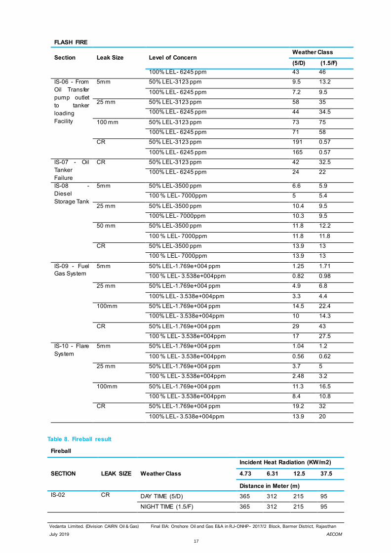
FLASH FIRE
Section Leak Size Level of Concern Weather Class
(5/D) (1.5/F)
100% LEL- 6245 ppm 43 46
IS-06 - From
Oil Transfer
pump outlet
to tanker
loading
Facility
5mm 50% LEL-3123 ppm 9.5 13.2
100% LEL- 6245 ppm 7.2 9.5
25 mm 50% LEL-3123 ppm 58 35
100% LEL- 6245 ppm 44 34.5
100 mm 50% LEL-3123 ppm 73 75
100% LEL- 6245 ppm 71 58
CR 50% LEL-3123 ppm 191 0.57
100% LEL- 6245 ppm 165 0.57
IS-07 - Oil
Tanker
Failure
CR 50% LEL-3123 ppm 42 32.5
100% LEL- 6245 ppm 24 22
IS-08 -
Diesel
Storage Tank
5mm 50% LEL-3500 ppm 6.6 5.9
100 % LEL- 7000ppm 5 5.4
25 mm 50% LEL-3500 ppm 10.4 9.5
100% LEL- 7000ppm 10.3 9.5
50 mm 50% LEL-3500 ppm 11.8 12.2
100 % LEL- 7000ppm 11.8 11.8
CR 50% LEL-3500 ppm 13.9 13
100 % LEL- 7000ppm 13.9 13
IS-09 - Fuel
Gas System
5mm 50% LEL-1.769e+004 ppm 1.25 1.71
100 % LEL- 3.538e+004ppm 0.82 0.98
25 mm 50% LEL-1.769e+004 ppm 4.9 6.8
100% LEL- 3.538e+004ppm 3.3 4.4
100mm 50% LEL-1.769e+004 ppm 14.5 22.4
100% LEL- 3.538e+004ppm 10 14.3
CR 50% LEL-1.769e+004 ppm 29 43
100 % LEL- 3.538e+004ppm 17 27.5
IS-10 - Flare
System
5mm 50% LEL-1.769e+004 ppm 1.04 1.2
100 % LEL- 3.538e+004ppm 0.56 0.62
25 mm 50% LEL-1.769e+004 ppm 3.7 5
100 % LEL- 3.538e+004ppm 2.48 3.2
100mm 50% LEL-1.769e+004 ppm 11.3 16.5
100 % LEL- 3.538e+004ppm 8.4 10.8
CR 50% LEL-1.769e+004 ppm 19.2 32
100% LEL- 3.538e+004ppm 13.9 20
Table 8. Fireball result
Fireball
SECTION LEAK SIZE Weather Class
Incident Heat Radiation (KW/m2)
4.73 6.31 12.5 37.5
Distance in Meter (m)
IS-02 CR DAY TIME (5/D) 365 312 215 95
NIGHT TIME (1.5/F) 365 312 215 95
Vedanta Limited. (Division CAIRN Oil & Gas) Final EIA: Onshore Oil and Gas E&A in RJ-ONHP- 2017/2 Block, Barmer District, Rajasthan
July 2019 AECOM
18
TNO Multi energy model has been used for the study and explosion is not envisaged for the desired overpressure
levels (0.0268, 0.070, 0.1379,0.2068 and 1 bar)
1.2.17. Risk Calculation Risk Calculation is done by combining the Consequence Analysis results given vide section 8.3 with the estimated
failure frequency and estimates of population within and outside the facility. However, other key study assumptions
were discussed with Vedanta Limited (Division Cairn Oil & Gas).
1.2.18. Population The following plant population has been assumed for the study: -
Table 9. Population
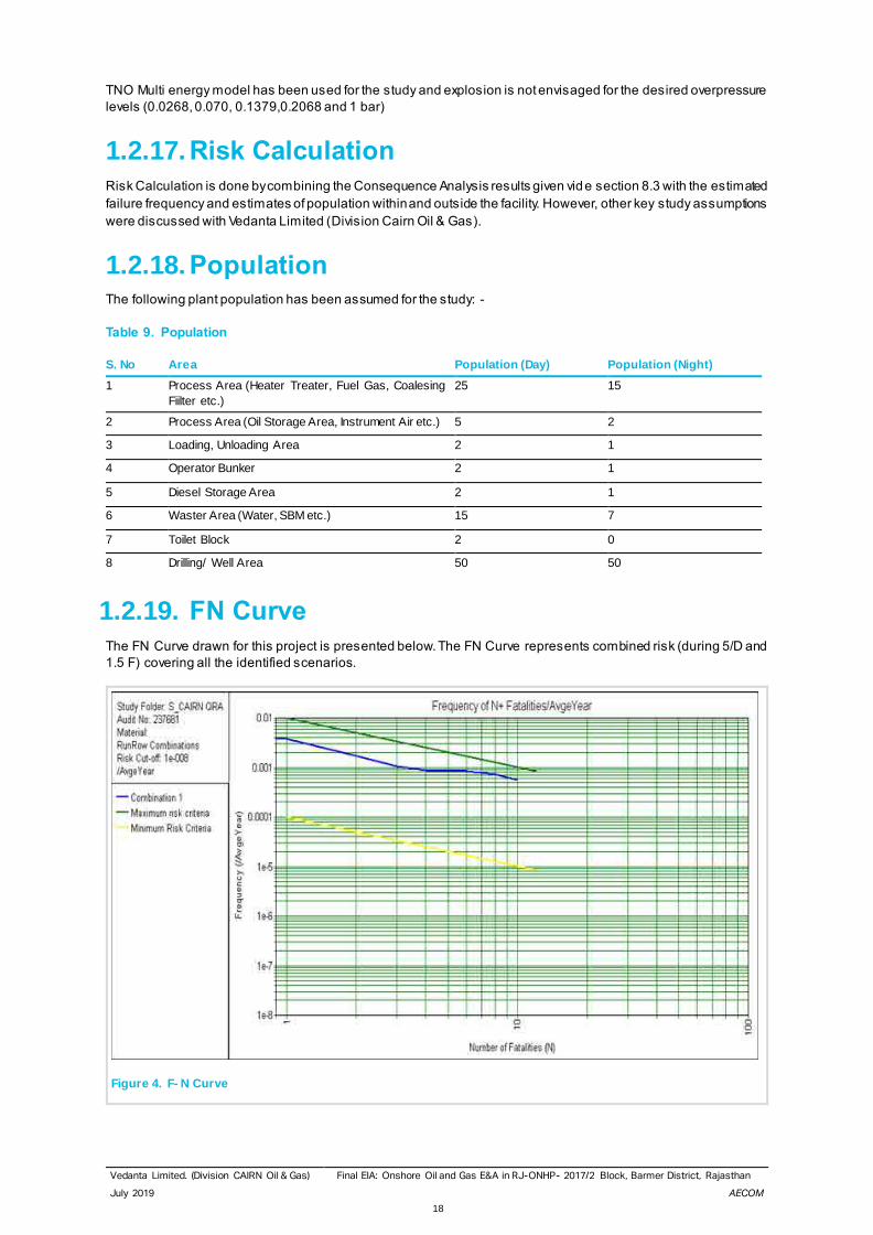
1.2.19. FN Curve The FN Curve drawn for this project is presented below. The FN Curve represents combined risk (during 5/D and
1.5 F) covering all the identified scenarios.
Figure 4. F- N Curve
S. No Area Population (Day) Population (Night)
1 Process Area (Heater Treater, Fuel Gas, Coalesing
Fiilter etc.)
25 15
2 Process Area (Oil Storage Area, Instrument Air etc.) 5 2
3 Loading, Unloading Area 2 1
4 Operator Bunker 2 1
5 Diesel Storage Area 2 1
6 Waster Area (Water, SBM etc.) 15 7
7 Toilet Block 2 0
8 Drilling/ Well Area 50 50
Vedanta Limited. (Division CAIRN Oil & Gas) Final EIA: Onshore Oil and Gas E&A in RJ-ONHP- 2017/2 Block, Barmer District, Rajasthan
July 2019 AECOM
19
From the above F-N Curve, it may be seen that the maximum line starts at 1E-02 and 1E-04 and it is observed that
the integrated risks lie within the 1E-02 and 1E-04, Hence the risk is in “ALARP” range. -this suggests that existing
risk mitigating measures must be sustained and other Best Industry Practices shall be used. Any specific new risk
reduction options may be evaluated through Cost Benefit Analysis (CBA) or any other suitable means.
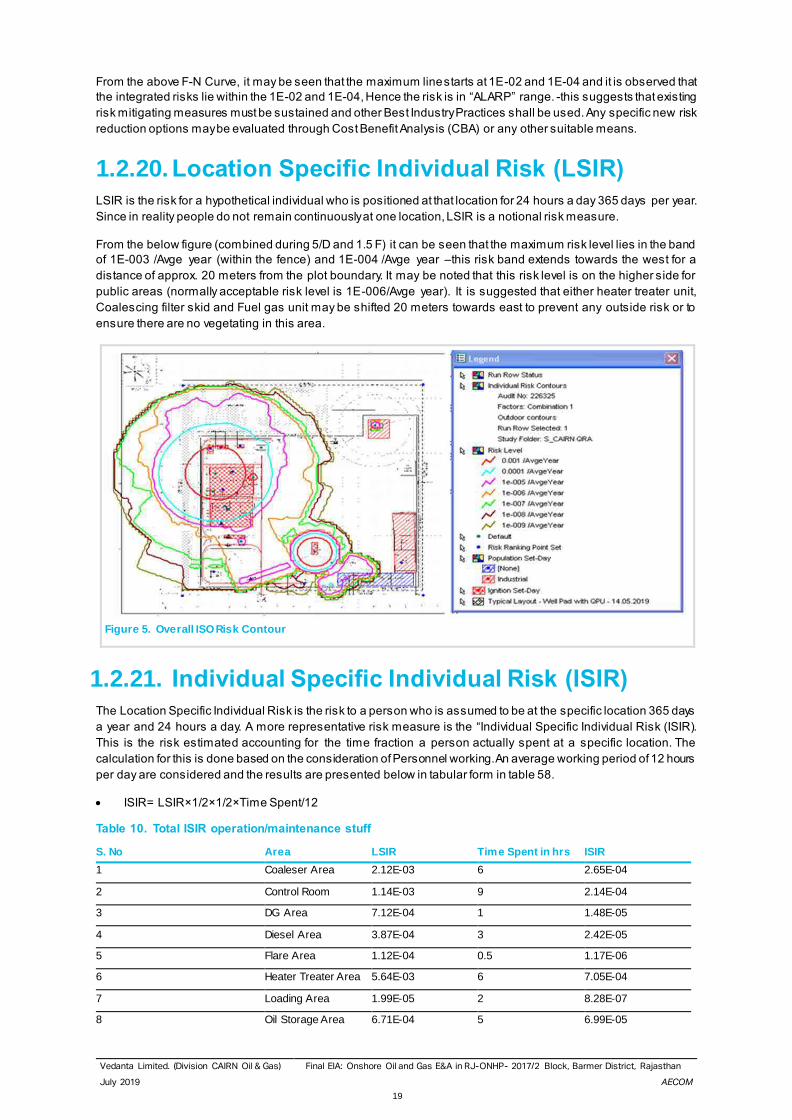
1.2.20. Location Specific Individual Risk (LSIR) LSIR is the risk for a hypothetical individual who is positioned at that location for 24 hours a day 365 days per year.
Since in reality people do not remain continuously at one location, LSIR is a notional risk measure.
From the below figure (combined during 5/D and 1.5 F) it can be seen that the maximum risk level lies in the band
of 1E-003 /Avge year (within the fence) and 1E-004 /Avge year –this risk band extends towards the west for a
distance of approx. 20 meters from the plot boundary. It may be noted that this risk level is on the higher side for
public areas (normally acceptable risk level is 1E-006/Avge year). It is suggested that either heater treater unit,
Coalescing filter skid and Fuel gas unit may be shifted 20 meters towards east to prevent any outside risk or to
ensure there are no vegetating in this area.
Figure 5. Overall ISO Risk Contour
1.2.21. Individual Specific Individual Risk (ISIR) The Location Specific Individual Risk is the risk to a person who is assumed to be at the specific location 365 days
a year and 24 hours a day. A more representative risk measure is the “Individual Specific Individual Risk (ISIR).
This is the risk estimated accounting for the time fraction a person actually spent at a specific location. The
calculation for this is done based on the consideration of Personnel working. An average working period of 12 hours
per day are considered and the results are presented below in tabular form in table 58.
• ISIR= LSIR×1/2×1/2×Time Spent/12
Table 10. Total ISIR operation/maintenance stuff
S. No Area LSIR Time Spent in hrs ISIR
1 Coaleser Area 2.12E-03 6 2.65E-04
2 Control Room 1.14E-03 9 2.14E-04
3 DG Area 7.12E-04 1 1.48E-05
4 Diesel Area 3.87E-04 3 2.42E-05
5 Flare Area 1.12E-04 0.5 1.17E-06
6 Heater Treater Area 5.64E-03 6 7.05E-04
7 Loading Area 1.99E-05 2 8.28E-07
8 Oil Storage Area 6.71E-04 5 6.99E-05
Vedanta Limited. (Division CAIRN Oil & Gas) Final EIA: Onshore Oil and Gas E&A in RJ-ONHP- 2017/2 Block, Barmer District, Rajasthan
July 2019 AECOM
20
S. No Area LSIR Time Spent in hrs ISIR
9 Well Area 5.86E-03 4 4.88E-04
10 Fuel Gas Area 2.02E-03 5 2.10E-04
Total 3.44E-06
Table 11. Total ISIR non operation/maintenance stuff
S. No Area LSIR Time Spent in hrs ISIR
1 Fire Water Area 1.29E-08 2 5.38E-10
2 Toilet Block 1.29E-08 1 2.69E-10
3 Security Cabin 1.00E-07 10 2.08E-08
4 Operator Block 1.00E-07 4 8.33E-09
Total 3.00E-08
From the above values it is seen that the operation/maintenance ISIR value is in ALARP range for operation person
and broadly acceptable for Non-operation. The following measures are available to address the same.
• Safeguarding of human life is Cairn Oil & Gas top most priority. To this effect, Vedanta Limited (Division Cairn
Oil & Gas) has issued and implemented a comprehensive HSE POLICY backed up with appropriate safety
management systems and procedures.
• Vedanta Limited (Division Cairn Oil & Gas) operating procedures lay a strong focus on hazard identification
and risk assessment covering each and every hazardous operation, procedure and equipment. Risks and
mitigating measures for each are clearly carried out and measures implemented and monitored. This ensures
risk minimisation to the worker group.
• The facility to be built based on the applicable National / International codes and best practice. Individual
equipment is of highest quality, certified and of highest safety integrity. This ensures risk minimisation to the
worker group through operational and maintenance periods. In addition, equipment hazard identification has
to be carried out for each of the equipment time to time.
• Mock drills should be carried out periodically to ensure the highest state of emergency response in case of
any incident
1.2.22. Risk Reduction Measures The main conclusions drawn from the Consequence Analysis and Risk calculations are given below- critical actions
for safeguarding against the incidents are also mentioned below: -
• From the F-N Curve, it is observed that the integrated risks lie within the “ALARP” range. -this suggests
existing risk mitigating measures must be sustained and Best Industry Practices be used. Any specific new
risk reduction options may be evaluated through Cost Benefit Analysis (CBA).
• it can be seen that the maximum risk level lies in the band of 1E-003 /Avge year (within the fence) and 1E-
004 /Avge year –this risk band extends towards the west for a distance of approx. 20 meters from the plot
boundary. It may be noted that this risk level is on the higher side for public areas (normally acceptable risk
level is 1E-006/Avge year). It is suggested that either heater treater unit, Coalescing filter skid and Fuel gas
unit may be shifted 20 meters towards east to prevent any outside risk or to ensure there are no vegetating
in this area.
• It is seen that the control room is falls under 1E-03 /Avge year it advised to shift the Control room to a safe
location.
• As Living areas are likely to be affected due to large incidents on the Rig Floor, it is essential to ensure the
upkeep of the safety devices (Smoke Detection, Fast Rescue Craft (FRC), escape routes and it must be
ensured that Mock evacuation drills are carried out periodically.
• Escape routes for personnel on the Drill Floor towards the LQ must be properly protected and kept free of
any debris/obstructions etc. to ensure minimum loss of life.
• The correct installation of Safety Critical Equipment and their operational reliability are essential for the safety
of the facility. In addition, initial and periodic testing of the Safety Critical Equipment before installation and
periodically is absolutely essential and the same must be ensured.
Vedanta Limited. (Division CAIRN Oil & Gas) Final EIA: Onshore Oil and Gas E&A in RJ-ONHP- 2017/2 Block, Barmer District, Rajasthan
July 2019 AECOM
21
• Storage tank enclosures must be drained periodically during the rainy season in particular.
• As hydrocarbon related risks exist at the facility, ignition source control must be ensured during routine and
non-routine operations.
• Ensuring that the public in vicinity of the facility is made aware of the hazards and also the hazards of
unplanned and irregular third-party activities- this may be done through frequent safety awareness
programmes, warning signage, explicit display of Do’s and Don’ts etc.
• Emergency Response Drills must be carried out frequently both internally within Vedanta Limited (Division
Cairn Oil & Gas) and also involving external authorities. Lessons learnt must be assimilated and disseminated
to concerned persons.
• The correct installation of the Safety Critical Equipment and their operational reliability are essential for the
safety of the facility. In addition, initial and periodic testing of the Safety Critical Equipment before installation
and periodically is essential and the same must be ensured.
• For Jetfire scenarios for small leaks may be safeguarded against through proper fire protection means (Fire
and gas Detectors, Passive and Active firefighting systems . Proper firefighting system design and
implementation and fire drills, training etc. are essential and must be sustained through the project life cycle.
• The damage distance arises due to the Flash Fire mitigated by ensuring the that the area must be kept free
of ignition sources to the extent possible and the same must be ensured even during maintenance act ivity.
Non-sparking tools must be used and personnel entering the area must be “de-earthed” before entering. A
hazardous area classification study is suggested for placement of electrical equipment in the classified area.
• The damage distance for pool fire arising due the pool fire for small leaks shall be safeguarded against through
proper fire protection means
• Key non-routine activities must be preceded by a Job Safety Analysis and Job or Task Risk Assessment
involving key personnel that would be working on the facility.
• Work Permit System must be implemented during the construction and operational phases of the project to
safeguard against any accidents. It must subsequently also cover the operational phase.
• Trips and falls hazard, electrical hazards etc. must be minimized through periodic safety audits and site
inspections using third party and Internal audit teams. Actions arising out of the audits must be implemented
in a time bound manner and followed up for closure.
• Vedanta Limited (Division Cairn Oil & Gas) must ensure suitable training to all personnel (Company as well
as Contractor personnel) to help prevent incidents/ accidents- such training must be refreshed periodically,
and a list of trained personnel must be maintained by Vedanta L imited (Division Cairn Oil & Gas)
• As ignition related risks exist at the facility, ignition source control must be ensured during routine and non-
routine operations.
• Apart from the process risks assessed, another very important category of incidents possib le are those
associated with well operations. These risks could include uncontrolled blowouts, incidents associated with
rig movement/rig walk, wireline risks during wireline operations, well bore clean out risks, risks associated
with specific chemicals during drilling/well repair/ activation/other activities.
• On-site personnel are subject to standard occupational risks and Vedanta Limited (Division Cairn Oil & Gas)
must direct effort and resources into reducing these risks. Incidents connected with well operations, dropped
objects, personnel falls from height, electrocution incidents etc. are top priorities which Vedanta Limited
(Division Cairn Oil & Gas) should concentrate significant effort to prevent, prepare for and respond to. This
must be implemented through the Vedanta Limited (Division Cairn Oil & Gas) HSE Management System.
• HAZOP to be done once design is reasonably complete and before start up. In addition, a basic safeguarding
must be in place during the testing/early production phase- well shut/ surface facilities basic shut down must
be possible. A basic functioning F&G system too must be put in place with well shut down incase of F&G
activation. Initial phase well behavior could be unpredictable and necessary safeguarding must be in place-
essentially, the EPU must be equipped with basic shutdown facilities, typically “fit for purpose”. It is also
necessary that initial well operations are manned continuously- this of course, will be the case, since data
logging/monitoring would also be taking place.
• Storage Tank vents to be routed at safe height and location to acvoid toxic/sudden vapour egress with
toxic/flammable hazard.
Vedanta Limited. (Division CAIRN Oil & Gas) Final EIA: Onshore Oil and Gas E&A in RJ-ONHP- 2017/2 Block, Barmer District, Rajasthan
July 2019 AECOM
22
• Heater Treater BMS to be checked thoroughly before being put on line and necessary leak and performance
tests to be ensured properly. Burner light up sequences should be properly established and necessary site
verification tests etc. carried out
• Specific procedures to address sanding operations/ sand flushout must be in place.
• It must be ensured that Storage Tanks and Road Tankers are NOT overfilled (not more than 80%)- set points/
SOP to capture the same
• Road Tanker Bottom filling option is preferred- in case of top loading, OISD 157
(https://oilweb.oilindia.in/OISD_Standard/oisd%20standard_old/Std-157.doc) guidelines to be followed for
critical points
• Ensure proper (metallic/ metal braided) hoses, gaskets etc. and Road tanker earthing is properly executed.
• F&G system periodic testing and maintenance to be ensured to prevent major escalation scenario.
• Periodic cleaning to be ensured for flame arrestors of storage tanks to prevent any Blockage/LOC scenario.
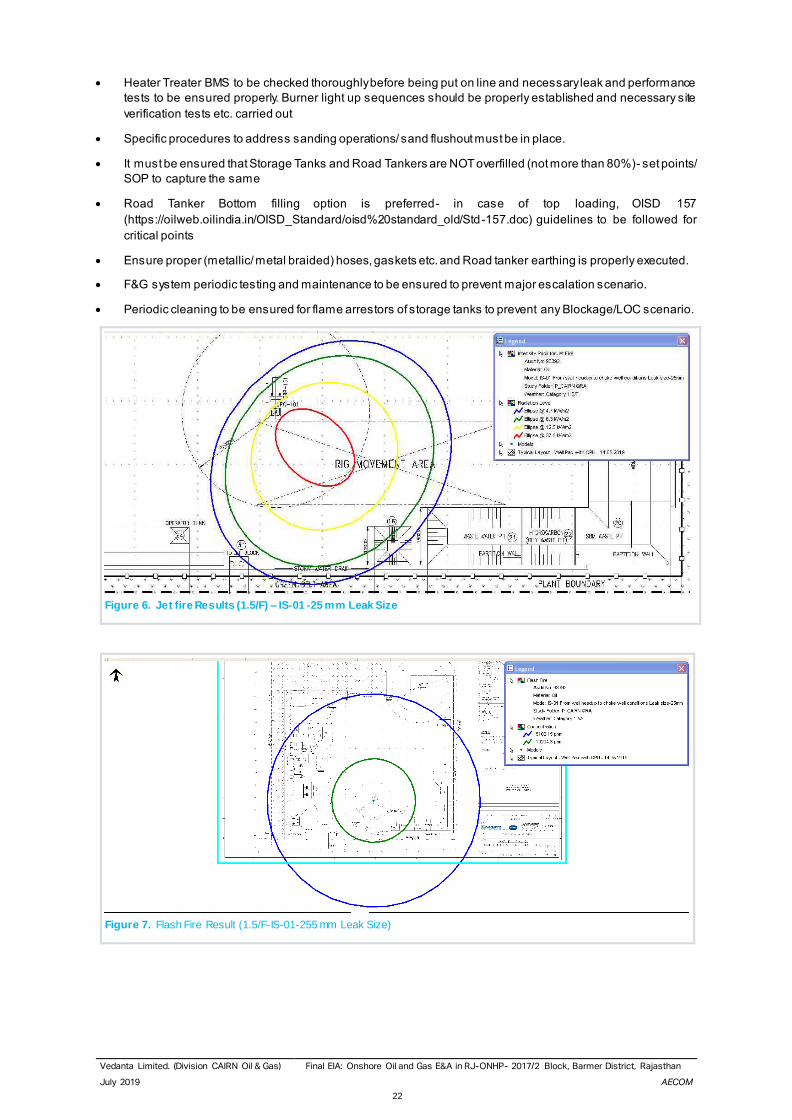
Figure 6. Jet fire Results (1.5/F) – IS-01 -25 mm Leak Size
Figure 7. Flash Fire Result (1.5/F-IS-01-255 mm Leak Size)
Vedanta Limited. (Division CAIRN Oil & Gas) Final EIA: Onshore Oil and Gas E&A in RJ-ONHP- 2017/2 Block, Barmer District, Rajasthan
July 2019 AECOM
23
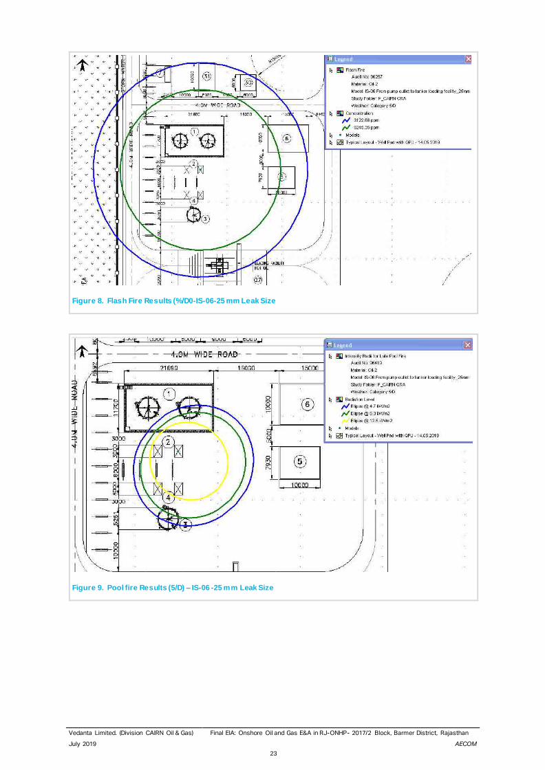
Figure 8. Flash Fire Results (%/D0-IS-06-25 mm Leak Size
Figure 9. Pool fire Results (5/D) – IS-06 -25 mm Leak Size
Vedanta Limited. (Division CAIRN Oil & Gas) Final EIA: Onshore Oil and Gas E&A in RJ-ONHP- 2017/2 Block, Barmer District, Rajasthan
July 2019 AECOM
24
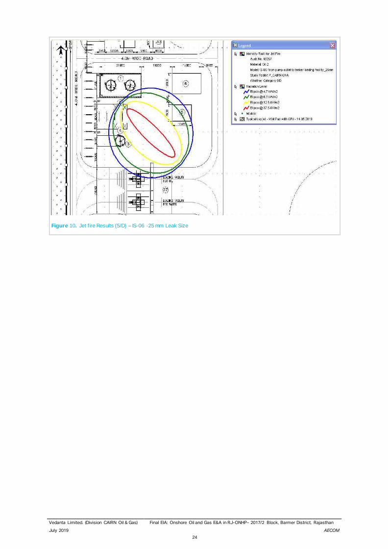
Figure 10. Jet f ire Results (5/D) – IS-06 -25 mm Leak Size


