35
October 2018 NI 653 DT R00 Guidance Note Risk-Based Structural Integrity Management for Topside Structures RULES & GUIDANCE NOTES

October 2018NI 653 DT R00
Guidance Note
Risk-Based Structural Integrity Management
for Topside Structures
RULES & GUIDANCE NOTES
BUREAU VERITAS MARINE & OFFSHORE
GENERAL CONDITIONS
1. INDEPENDENCE OF THE SOCIETY AND APPLICABLE TERMS1.1 The Society shall remain at all times an independent contractor and neither the Society nor any of its officers,employees, servants, agents or subcontractors shall be or act as an employee, servant or agent of any other partyhereto in the performance of the Services.1.2 The operations of the Society in providing its Services are exclusively conducted by way of random inspectionsand do not, in any circumstances, involve monitoring or exhaustive verification.1.3 The Society acts as a services provider. This cannot be construed as an obligation bearing on the Society toobtain a result or as a warranty. The Society is not and may not be considered as an underwriter, broker in Unit’s saleor chartering, expert in Unit’s valuation, consulting engineer, controller, naval architect, designer, manufacturer,shipbuilder, repair or conversion yard, charterer or shipowner; none of them above listed being relieved of any of theirexpressed or implied obligations as a result of the interventions of the Society.1.4 The Society only is qualified to apply and interpret its Rules.1.5 The Client acknowledges the latest versions of the Conditions and of the applicable Rules applying to theServices’ performance.1.6 Unless an express written agreement is made between the Parties on the applicable Rules, the applicable Rulesshall be the Rules applicable at the time of entering into the relevant contract for the performance of the Services.1.7 The Services’ performance is solely based on the Conditions. No other terms shall apply whether express orimplied.
2. DEFINITIONS2.1 “Certificate(s)” means classification or statutory certificates, attestations and reports following the Society’sintervention.2.2 “Certification” means the activity of certification in application of national and international regulations orstandards, in particular by delegation from different governments that can result in the issuance of a Certificate.2.3 “Classification” means the classification of a Unit that can result or not in the issuance of a classificationCertificate with reference to the Rules. Classification is an appraisement given by the Society to the Client, at a certaindate, following surveys by its surveyors on the level of compliance of the Unit to the Society’s Rules or to thedocuments of reference for the Services provided. They cannot be construed as an implied or express warranty ofsafety, fitness for the purpose, seaworthiness of the Unit or of its value for sale, insurance or chartering.2.4 “Client” means the Party and/or its representative requesting the Services.2.5 “Conditions” means the terms and conditions set out in the present document.2.6 “Industry Practice” means international maritime and/or offshore industry practices.2.7 “Intellectual Property” means all patents, rights to inventions, utility models, copyright and related rights,trade marks, logos, service marks, trade dress, business and domain names, rights in trade dress or get-up, rights ingoodwill or to sue for passing off, unfair competition rights, rights in designs, rights in computer software, databaserights, topography rights, moral rights, rights in confidential information (including know-how and trade secrets),methods and protocols for Services, and any other intellectual property rights, in each case whether capable ofregistration, registered or unregistered and including all applications for and renewals, reversions or extensions ofsuch rights, and all similar or equivalent rights or forms of protection in any part of the world.2.8 “Parties” means the Society and Client together.2.9 “Party” means the Society or the Client.2.10 “Register” means the public electronic register of ships updated regularly by the Society.2.11 “Rules” means the Society’s classification rules and other documents. The Society’s Rules take into accountat the date of their preparation the state of currently available and proven technical minimum requirements but arenot a standard or a code of construction neither a guide for maintenance, a safety handbook or a guide of professionalpractices, all of which are assumed to be known in detail and carefully followed at all times by the Client.2.12 “Services” means the services set out in clauses 2.2 and 2.3 but also other services related to Classificationand Certification such as, but not limited to: ship and company safety management certification, ship and port securitycertification, maritime labour certification, training activities, all activities and duties incidental thereto such asdocumentation on any supporting means, software, instrumentation, measurements, tests and trials on board. TheServices are carried out by the Society according to the applicable referential and to the Bureau Veritas’ Code ofEthics. The Society shall perform the Services according to the applicable national and international standards andIndustry Practice and always on the assumption that the Client is aware of such standards and Industry Practice.2.13 “Society” means the classification society ‘Bureau Veritas Marine & Offshore SAS’, a company organizedand existing under the laws of France, registered in Nanterre under number 821 131 844, or any other legal entity ofBureau Veritas Group as may be specified in the relevant contract, and whose main activities are Classification andCertification of ships or offshore units.2.14 “Unit” means any ship or vessel or offshore unit or structure of any type or part of it or system whether linkedto shore, river bed or sea bed or not, whether operated or located at sea or in inland waters or partly on land, includingsubmarines, hovercrafts, drilling rigs, offshore installations of any type and of any purpose, their related and ancillaryequipment, subsea or not, such as well head and pipelines, mooring legs and mooring points or otherwise as decidedby the Society.
3. SCOPE AND PERFORMANCE3.1 Subject to the Services requested and always by reference to the Rules, the Society shall:• review the construction arrangements of the Unit as shown on the documents provided by the Client;• conduct the Unit surveys at the place of the Unit construction;• class the Unit and enter the Unit’s class in the Society’s Register;• survey the Unit periodically in service to note whether the requirements for the maintenance of class are met.The Client shall inform the Society without delay of any circumstances which may cause any changes on theconducted surveys or Services.3.2 The Society will not:• declare the acceptance or commissioning of a Unit, nor its construction in conformity with its design, suchactivities remaining under the exclusive responsibility of the Unit’s owner or builder;• engage in any work relating to the design, construction, production or repair checks, neither in the operation ofthe Unit or the Unit’s trade, neither in any advisory services, and cannot be held liable on those accounts.
4. RESERVATION CLAUSE4.1 The Client shall always: (i) maintain the Unit in good condition after surveys; (ii) present the Unit for surveys;and (iii) inform the Society in due time of any circumstances that may affect the given appraisement of the Unit orcause to modify the scope of the Services.4.2 Certificates are only valid if issued by the Society.4.3 The Society has entire control over the Certificates issued and may at any time withdraw a Certificate at itsentire discretion including, but not limited to, in the following situations: where the Client fails to comply in due timewith instructions of the Society or where the Client fails to pay in accordance with clause 6.2 hereunder.4.4 The Society may at times and at its sole discretion give an opinion on a design or any technical element thatwould ‘in principle’ be acceptable to the Society. This opinion shall not presume on the final issuance of any Certificateor on its content in the event of the actual issuance of a Certificate. This opinion shall only be an appraisal made bythe Society which shall not be held liable for it.
5. ACCESS AND SAFETY5.1 The Client shall give to the Society all access and information necessary for the efficient performance of therequested Services. The Client shall be the sole responsible for the conditions of presentation of the Unit for tests,trials and surveys and the conditions under which tests and trials are carried out. Any information, drawing, etc.required for the performance of the Services must be made available in due time.5.2 The Client shall notify the Society of any relevant safety issue and shall take all necessary safety-relatedmeasures to ensure a safe work environment for the Society or any of its officers, employees, servants, agents orsubcontractors and shall comply with all applicable safety regulations.
6. PAYMENT OF INVOICES6.1 The provision of the Services by the Society, whether complete or not, involve, for the part carried out, thepayment of fees thirty (30) days upon issuance of the invoice.
Bureau Veritas Marine & Offshore Genera
6.2 Without prejudice to any other rights hereunder, in case of Client’s payment default, the Society shall be entitledto charge, in addition to the amount not properly paid, interests equal to twelve (12) months LIBOR plus two (2) percent as of due date calculated on the number of days such payment is delinquent. The Society shall also have theright to withhold Certificates and other documents and/or to suspend or revoke the validity of Certificates.6.3 In case of dispute on the invoice amount, the undisputed portion of the invoice shall be paid and an explanationon the dispute shall accompany payment so that action can be taken to solve the dispute.
7. LIABILITY7.1 The Society bears no liability for consequential loss. For the purpose of this clause consequential loss shallinclude, without limitation:• Indirect or consequential loss;• Any loss and/or deferral of production, loss of product, loss of use, loss of bargain, loss of revenue, loss of profitor anticipated profit, loss of business and business interruption, in each case whether direct or indirect.The Client shall defend, release, save, indemnify, defend and hold harmless the Society from the Client’s ownconsequential loss regardless of cause.7.2 Except in case of wilful misconduct of the Society, death or bodily injury caused by the Society’s negligenceand any other liability that could not be, by law, limited, the Society’s maximum liability towards the Client is limitedto one hundred and fifty per-cents (150%) of the price paid by the Client to the Society for the Services having causedthe damage. This limit applies to any liability of whatsoever nature and howsoever arising, including fault by theSociety, breach of contract, breach of warranty, tort, strict liability, breach of statute.7.3 All claims shall be presented to the Society in writing within three (3) months of the completion of Services’performance or (if later) the date when the events which are relied on were first discovered by the Client. Any claimnot so presented as defined above shall be deemed waived and absolutely time barred.
8. INDEMNITY CLAUSE8.1 The Client shall defend, release, save, indemnify and hold harmless the Society from and against any and allclaims, demands, lawsuits or actions for damages, including legal fees, for harm or loss to persons and/or propertytangible, intangible or otherwise which may be brought against the Society, incidental to, arising out of or inconnection with the performance of the Services (including for damages arising out of or in connection with opinionsdelivered according to clause 4.4 above) except for those claims caused solely and completely by the grossnegligence of the Society, its officers, employees, servants, agents or subcontractors.
9. TERMINATION9.1 The Parties shall have the right to terminate the Services (and the relevant contract) for convenience aftergiving the other Party thirty (30) days’ written notice, and without prejudice to clause 6 above.9.2 In such a case, the Classification granted to the concerned Unit and the previously issued Certificates shall remainvalid until the date of effect of the termination notice issued, subject to compliance with clause 4.1 and 6 above.9.3 In the event where, in the reasonable opinion of the Society, the Client is in breach, or is suspected to be inbreach of clause 16 of the Conditions, the Society shall have the right to terminate the Services (and the relevantcontracts associated) with immediate effect.
10. FORCE MAJEURE10.1 Neither Party shall be responsible or liable for any failure to fulfil any term or provision of the Conditions if andto the extent that fulfilment has been delayed or temporarily prevented by a force majeure occurrence without the faultor negligence of the Party affected and which, by the exercise of reasonable diligence, the said Party is unable toprovide against.10.2 For the purpose of this clause, force majeure shall mean any circumstance not being within a Party’sreasonable control including, but not limited to: acts of God, natural disasters, epidemics or pandemics, wars, terroristattacks, riots, sabotages, impositions of sanctions, embargoes, nuclear, chemical or biological contaminations, lawsor action taken by a government or public authority, quotas or prohibition, expropriations, destructions of the worksite,explosions, fires, accidents, any labour or trade disputes, strikes or lockouts.
11. CONFIDENTIALITY11.1 The documents and data provided to or prepared by the Society in performing the Services, and the informationmade available to the Society, are treated as confidential except where the information:• is properly and lawfully in the possession of the Society;• is already in possession of the public or has entered the public domain, otherwise than through a breach of thisobligation;• is acquired or received independently from a third party that has the right to disseminate such information;• is required to be disclosed under applicable law or by a governmental order, decree, regulation or rule or by astock exchange authority (provided that the receiving Party shall make all reasonable efforts to give prompt writtennotice to the disclosing Party prior to such disclosure.11.2 The Parties shall use the confidential information exclusively within the framework of their activity underlyingthese Conditions.11.3 Confidential information shall only be provided to third parties with the prior written consent of the other Party.However, such prior consent shall not be required when the Society provides the confidential information to asubsidiary.11.4 Without prejudice to sub-clause 11.1, the Society shall have the right to disclose the confidential information ifrequired to do so under regulations of the International Association of Classifications Societies (IACS) or any statutoryobligations.
12. INTELLECTUAL PROPERTY12.1 Each Party exclusively owns all rights to its Intellectual Property created before or after the commencementdate of the Conditions and whether or not associated with any contract between the Parties.12.2 The Intellectual Property developed by the Society for the performance of the Services including, but not limitedto drawings, calculations, and reports shall remain the exclusive property of the Society.
13. ASSIGNMENT13.1 The contract resulting from to these Conditions cannot be assigned or transferred by any means by a Party toany third party without the prior written consent of the other Party.13.2 The Society shall however have the right to assign or transfer by any means the said contract to a subsidiaryof the Bureau Veritas Group.
14. SEVERABILITY14.1 Invalidity of one or more provisions does not affect the remaining provisions.14.2 Definitions herein take precedence over other definitions which may appear in other documents issued by theSociety.14.3 In case of doubt as to the interpretation of the Conditions, the English text shall prevail.
15. GOVERNING LAW AND DISPUTE RESOLUTION15.1 These Conditions shall be construed and governed by the laws of England and Wales.15.2 The Parties shall make every effort to settle any dispute amicably and in good faith by way of negotiation withinthirty (30) days from the date of receipt by either one of the Parties of a written notice of such a dispute.15.3 Failing that, the dispute shall finally be settled under the Rules of Arbitration of the Maritime Arbitration Chamberof Paris (“CAMP”), which rules are deemed to be incorporated by reference into this clause. The number of arbitratorsshall be three (3). The place of arbitration shall be Paris (France). The Parties agree to keep the arbitrationproceedings confidential.
16. PROFESSIONAL ETHICS16.1 Each Party shall conduct all activities in compliance with all laws, statutes, rules, economic and trade sanctions(including but not limited to US sanctions and EU sanctions) and regulations applicable to such Party including butnot limited to: child labour, forced labour, collective bargaining, discrimination, abuse, working hours and minimumwages, anti-bribery, anti-corruption, copyright and trademark protection, personal data protection (https://personaldataprotection.bureauveritas.com/privacypolicy).Each of the Parties warrants that neither it, nor its affiliates, has made or will make, with respect to the mattersprovided for hereunder, any offer, payment, gift or authorization of the payment of any money directly or indirectly, toor for the use or benefit of any official or employee of the government, political party, official, or candidate.16.2 In addition, the Client shall act consistently with the Bureau Veritas’ Code of Ethics.https://group.bureauveritas.com/group/corporate-social-responsibility
l Conditions – Edition September 2018

GUIDANCE NOTE NI 653
NI 653Risk-Based Structural Integrity Management
for Topside Structures
SECTION 1 GENERAL
SECTION 2 REVIEW OF EXISTING GUIDELINES
SECTION 3 RISK-BASED INSPECTION PLANNING METHOD
APPENDIX 1 TYPICAL TOPSIDES STRUCTURAL SIM DATA
APPENDIX 2 TYPICAL CRITICAL STRUCTURES
APPENDIX 3 ASSESSMENT OF COATING CONDITION
October 2018

Section 1 General
1 General 5
1.1 Context1.2 Scope of the document1.3 Overview of ISO guidance1.4 Overview of the Society’s method1.5 Organization of the document
2 References, Definitions and Acronyms 6
2.1 References2.2 Terms and definitions2.3 Acronyms
Section 2 Review of Existing Guidelines
1 General 9
1.1 Benefits of risk-based SIM
2 Overview of standards guidelines 9
2.1 General2.2 API2.3 ISO2.4 NORSOK
3 General requirements 10
3.1 Management framework3.2 Risk tolerance3.3 Data requirements3.4 Structural integrity interface3.5 Inspection Planning Process
4 Critical Structures 12
4.1 General4.2 ISO guidelines4.3 Guidelines from the JIP on SIM Topsides4.4 General guidelines
5 Performance Standards 13
5.1 General5.2 Structural performance standard5.3 Assessment of the condition of a degraded coating system5.4 Assessment of the condition of a degraded structure
6 Risk Assessment 15
6.1 General6.2 Consequence of failure6.3 Likelihood of failure6.4 Risk ranking
7 Inspection Strategy 16
2 Bureau Veritas October 2018
7.1 General7.2 Scope7.3 Periodic inspection strategy7.4 Particular considerations regarding the inspection planning of topsides
structures7.5 Maintenance strategy
8 Inspection Program 18
8.1 General8.2 Inspection specifications
Section 3 Risk-based Inspection Planning Method
1 General 20
1.1 Purpose1.2 Scope of application
2 Implementation 20
2.1 General2.2 RBI workshop2.3 Risk assessment2.4 Inspection strategy2.5 RBI updating
3 Risk Assessment Method 23
3.1 General3.2 Performance standard3.3 Likelihood of failure3.4 Calibration process of the LoF scoring3.5 Consequence of failure3.6 Risk ranking
4 Inspection Strategy 26
4.1 Default risk-based inspection intervals4.2 Default inspection scope of work4.3 Specific inspection plan
5 Inspection program 27
5.1 General5.2 Specification of the inspection program5.3 Execution of the inspection program
Appendix 1 Typical Topsides Structural SIM Data
1 Typical Examples of Topsides Structures SIM Data 28
1.1 Design data1.2 Fabrication and installation data1.3 Condition data1.4 Operational data1.5 Engineering data
October 2018 Bureau Veritas 3

Appendix 2 Typical Critical Structures
1 Typical Examples of CS 30
1.1 General1.2 Major accident1.3 Major environmental event1.4 Major accident prevention or mitigation1.5 Personnel safety1.6 Financial loss
Appendix 3 Assessment of Coating Condition
1 Corrosion Protection Coatings 31
1.1 General1.2 ISO1.3 SSPC1.4 ASTM
2 Passive Fire Protection 32
2.1 HSE qualitative categorization
4 Bureau Veritas October 2018

NI 653, Sec 1
SECTION 1 GENERAL
1 General
1.1 Context
1.1.1 Current industrial practice for the inspection of top-sides structures is based on API-RP-2SIM requirement thatinspection of topsides structure be performed annually byvisual examination. However, the final report of the JointIndustry Project (JIP) on the Structural Integrity Management(SIM) of topsides structures acknowledged that even if theannual visual inspection allows a high proportion of typicaldegradations to be detected, it may fail in detecting thosethat lead to a significant percentage of the reported failures(MSL, 2004). It proposed therefore a risk-based approach asan alternative to improve topsides inspection regimes. Thisleads to more frequent and detailed inspection of high-riskstructures increasing the likelihood of detecting earlyenough critical defect.
Following the release of the API-RP-2SIM which addressesthe issue of Risk-Based Inspection (RBI) especially for theunderwater structure of fixed offshore platforms, the devel-opment of guidance for the RBI of other offshore structures,especially topsides structures is being considered. In thisvein, the International Organization for Standardization(ISO) has developed a specific standard for the SIM of off-shore structures (ISO/DIS 19901-9) including topsides struc-tures in which guidance for performing RBI is provided.
1.2 Scope of the document
1.2.1 This Guidance Note is intended to sets out the mainrecommendations and requirements of the ISO/DIS 19901-9 for implementing a risk-based structural integrity manage-ment for offshore topsides structures. It includes, also, rele-vant guidance from other international standards and fromtechnical reports and research papers.
This Guidance Note presents also a generic RBI method ofthe Society for topsides structures. This method is based onISO guidance and is to be used as part of the SIM todevelop an inspection strategy.
1.3 Overview of ISO guidance
1.3.1 ISO/DIS 19901-9 includes guidance for risk-basedapproach to SIM of offshore topsides structures. Althoughmost of it is dedicated to fixed steel offshore structures (e.g.jackets, towers, etc), it covers also all topsides and structuresabove sea level, including but not limited to the main decks,deck legs, topsides modules, crane pedestals, helideck, drill-ing derrick, skid beams, flare booms, exhaust towers, radiotower, conductor support frames, and lifeboat davits.
1.3.2 The ISO recommends that risk-based approach fordeveloping SIM strategy be applied to safety-critical struc-tural items. For those ones a performance standard shouldbe established, that serves as a basis for appraising their risklevel and for defining the SIM strategy. A so-called MajorAccident Approach is recommended for selecting criticalstructural items and typical examples of critical structuralitems are provided in the appendix of the standard. How-ever, no guideline is provided on how to set up their perfor-mance standards.General guidelines for risk categorization in terms of theexposure category and the likelihood of failure are providedfor the whole platform. However, the basic principles areapplicable to topsides structures too.
Indicative risk-based inspection intervals are proposed forthe inspection planning of topsides critical structural items.The type of inspection, i.e. general visual inspection (GVI),close visual inspection (CVI) and/or none-destructive exam-ination (NDE), to be used with those intervals should beselected based on the type of expected deterioration/degra-dation and the present known condition of the topsides crit-ical structural item under consideration.
More detailed guidance is provided on the inspection pro-gram, including inspection specifications and requirementsfor using most of the inspection methods.
1.3.3 The ISO points out the necessity to take into account thestructural integrity interfaces in planning for the inspections.
1.3.4 ISO recommends also that a maintenance strategy beimplemented for those structures where significant degrada-tion mode are possible. The maintenance strategy shouldinclude coating maintenance and grating replacement andmay be defined on a risk analysis basis.
1.4 Overview of the Society’s method
1.4.1 The Society has developed a generic risk-basedinspection planning method to be used as part of the SIM oftopsides structures. In particular, the method:• adopts the general framework recommended by the ISO
for developing inspection plan• provides guidelines in selecting the critical structures on
which RBI should be applied• defines the minimum structural performance required
from the selected structures• develops a risk assessment method, using a rule-based
scoring approach for the likelihood of failure and a cate-gorization of the consequence of failure in terms of life-safety, environment and financial loss
• sets up a calibration process for the likelihood assess-ment that can include an owner or operator specific risktolerance criteria
October 2018 Bureau Veritas 5

NI 653, Sec 1
• develops risk-based inspection strategies in confor-mance to ISO recommendations.
The method reflects current industrial best practice and putsemphasize on the understanding of the risk.
1.5 Organization of the document
1.5.1 The existing guidelines for performing SIM for top-sides structures are set out in Sec 2.
• the requirements of the main standards, which addressSIM of topsides structures, are summarized
• the general requirements for SIM of topsides structuresare pointed out
• an emphasize is put on presenting requirements andrecommendation for developing risk-based inspectionplanning.
A generic risk-based inspection planning method devel-oped by the Society as part of the SIM of topsides structuresis presented in Sec 3.
Typical examples of structural data required for the SIM pro-cess are provided in App 1.
Typical examples topsides critical structures on which RBIshould be applied. are provided in App 2.
Existing guidelines for the assessment of the condition ofprotective coating systems are set out in App 3.
2 References, definitions and acronyms
2.1 References
2.1.1 Standards
API-RP-580, Risk-Based Inspection (2nd ed.). Washington:API Publishing Services, 2009.
API-RP-2SIM, Structural Integrity Management of Fixed Off-shore Structures (1st ed.). Washington: API Publishing Ser-vices, 2014.
ASTM D5065, Standard Guide for Assessing the Conditionof Aged Coatings on Steel Surfaces, 2013.
ASTM D610, Standard Practice for Evaluating Degree ofRusting on Painted Steel Surfaces, 2012.
ASTM D4214, Standard Test Methods for Evaluating theDegree of Chalking of Exterior Paint Films, 2015.
ASTM D660, Standard Test Method for Evaluating Degree ofChecking of Exterior Paints, 2011.
ASTM D714. Standard Test Method for Evaluating Degree ofBlistering of Paints, 2009.
ISO 19901-3, Petroleum and natural gas industries Spe-cific requirements for offshore structures Part 3: Topsidesstructure, 2014.
ISO/DIS-19901-9, Petroleum and natural gas industries Specific requirements for offshore structures Part 9: Struc-tural integrity management, 2017.
ISO 19902, Petroleum and natural gas industries Fixedsteel offshore structures, 2007.
ISO 4628, Paints and varnishes Evaluation of degradationof coatings Designation of quantity and size of defects,and of intensity of uniform changes in appearance - Part 1: General introduction and designation system,
2016.- Part 2: Assessment of degree of blistering, 2016.- Part 3: Assessment of degree of rusting, 2016.- Part 4: Assessment of degree of cracking, 2016.- Part 5: Assessment of degree of flaking, 2016.- Part 6: Assessment of degree of chalking by tape
method, 2011.- Part 7: Assessment of degree of chalking by velvet
method, 2016.- Part 8: Assessment of degree of delamination and corro-
sion around a scribe, 2013.- Part 10: Assessment of degree of filiform corrosion,
2016.
NORSOK N-005, Condition Monitoring of LoadbearingStructures, 2017.
NORSOK N-006, Assessment of structural integrity forexisting offshore load-bearing structures, 2015.
SSPC Visual Standard 2, Standard Method of EvaluatingDegree of Rusting on Painted Steel Surfaces, 2000.
2.1.2 Other guidanceHSE, Prevention of Fire & Explosion and EmergencyResponse on Offshore Installations, Approved Code of Prac-tice and Guidance, 2016.
HSE, Structural integrity management framework for fixedjacket structures, Research Report RR684, 2009.
HSE, Advice on acceptance criteria for damaged PassiveFire Protection (PFP) Coatings, Offshore Information SheetNo. 12/2007, 2007.
Step Change in Safety Assurance and Verification Practi-tioner's Guide, 2015.
2.1.3 JIP reportsMSL Engineering, Ltd. Guidelines of the Definition andReporting of Significant Damage to Fixed Steel OffshorePlatforms, JIP Report, 2003.
MSL Engineering, Ltd. Development of Integrity Method-ologies for the Topsides of Offshore Production Facilities,JIP Report, 2004.
2.1.4 Conferences papersAxelsen S. B., Knudsen O. O. and Johnsen R., ProtectiveCoatings Offshore: Introducing A Risk Based MaintenanceManagement System, NACE CORROSION conference &expo, USA, 2009.
Sharp J.V., Stacey A, Birkinshaw B., Application of Perfor-mance Standards to Offshore Structural Components,OMAE Conference, 1999.
Sharp, J. V., Ersdal, G. and Galbraith, D., Development ofkey performance indicators for offshore structural integrity,OMAE Conference, Portugal, 2008.
Versowsky, P. E., Rationalization and Optimization of Coat-ings Maintenance Programs for Corrosion Management onOffshore Platforms. Workshop on Coatings for Corrosion
6 Bureau Veritas October 2018
NI 653, Sec 1
Protection: Offshore Oil and Gas Operation Facilities,Marine Pipeline and Ship Structures and Port Facilities,National Institute of Standards and Technology, Biloxi, Mis-sissipi, 2004.
2.2 Terms and definitions
2.2.1 Anomaly
In-service survey measurement, which is outside the thresh-old acceptable from the design or most recent fitness-for-service assessment.
2.2.2 Assessment
Detailed qualitative or quantitative determination of thestructural component or system strength.
2.2.3 Consequence
Effects of an abnormal event, such as extreme metoceanevent, seismic event, ice or accidental event, on personnel,the environment, or the property.
2.2.4 Defect
Imperfection, fault, or flaw in a structural component.
2.2.5 Degradation / deterioration
Reduction in the ability of a component to provide itsintended purpose.
2.2.6 Evaluation
Review of condition of the structure compared to that whenit was last assessed and other parameters that affect theintegrity and risk levels to confirm or otherwise that theexisting structural assessments still apply.
2.2.7 Exposure level
The classification used to categorize the platform conse-quence of failure based on consideration of life safety, envi-ronmental pollution and business disruption.
Three exposure levels are used and they are defined as fol-lows:
• exposure level L-1 refers to manned-non-evacuatedplatforms or high consequence of failure platforms interms of environmental pollution or financial loss
• exposure level L-2 refers to manned-evacuated plat-forms or medium consequence of failure platforms
• exposure level L-3 refers to unmanned platforms or lowconsequence of failure platforms.
2.2.8 Failure
Insufficient strength or inadequate performance of a struc-ture or system, preventing it from fulfilling its intended per-formance requirements.
2.2.9 Fitness-for-service
Engineering evaluations performed to demonstrate thestructural integrity of structural component that could con-tain a flaw or damage or that could be operating under spe-cific conditions that could produce a failure.
2.2.10 In-process inspectionApplication of various tests on the structures or equipmentat each stage of the fabrication, the construction, the com-missioning, the transportation and the installation processesto ensure that they are installed in conformance with proj-ect specifications and/or industry standards.
2.2.11 In-service inspectionAll inspection activities associated with a structure once ithas been installed but before it is de-commissioned.
2.2.12 InspectionVisit to the platform and the associated survey activities forpurposes of collecting data required in evaluating its struc-tural integrity for continued operation.
2.2.13 Inspection planA plan for the in-service inspection of a structure including thescheduled dates and the expected scope of the inspections.
2.2.14 Inspection programScope of work for the offshore execution of the inspectionactivities to determine the condition of the structure
2.2.15 MaintenanceUpkeep of the required condition of the structure by proactiveintervention e.g. painting, repair, replacement, greasing...
2.2.16 MitigationLimitation of negative consequence or reduction in likeli-hood of particular event or condition.
2.2.17 OperatorThe person, firm, corporation, or other organizationemployed by the owners to conduct operations.
2.2.18 OwnerParty who owns the physical infrastructure and is responsi-ble for maintaining structural integrity.
2.2.19 Performance levelCriteria for which an existing platform should achieve toconfirm fitness-for-service.
2.2.20 Performance standardStatement of the performance required of a system, item ofequipment, person or procedure and which is used as thebasis for managing the hazard through the lifecycle of theplatform.
2.2.21 PolicyIntention and direction of the owner with respect to the SIMrelated processes and activities.
2.2.22 PracticeFormal document that establishes the technical criteria,methods and processes.
2.2.23 Primary, secondary and tertiary structural components/members
Primary structural components provide stiffness andstrength to the overall structure e.g. legs, all truss members,plate girders, horizontal bracing.
October 2018 Bureau Veritas 7
NI 653, Sec 1
Secondary structural components are essential to the localintegrity of the structure where failure of these componentswill not affect the overall integrity e.g. deck plate, deckbeam, main escape walkways and stairs, crane pedestal.
Tertiary structural components are ancillary structural com-ponents including minor structural members and attach-ments e.g. handrails, gratings, supports connections, antibuckling stiffeners of deck plate.
2.2.24 Procedure
Written directive, usually arranged chronologically, which providesdetails and steps required to perform a given activity.
2.2.25 Redundancy
Availability of alternate load paths in a structure followingthe failure of one or more structural components.
2.2.26 Residual strength
Ultimate strength of an offshore structure in a damagedcondition.
2.2.27 Review
Process used to determine how the SIM processes can beimproved on the basis of in house and external experienceand industry best practice.
2.2.28 Risk-based inspection
Inspection strategies developed from an evaluation of therisk associated with a structure with the intention of tailor-ing inspection scope and frequency to risk magnitude andlocation.
2.2.29 Robustness
Ability of a structure to tolerate damage without failure.
2.2.30 Service life
Time period associated with the structure’s anticipated endof field life or decommissioning date.
2.2.31 Strategy
Process for delivering the structural integrity consistent withthe SIM policy.
2.2.32 Structural analysis
Calculation to predict the behavior of the structure usuallyrelative to specified code requirements.
2.2.33 Structural assessment
Interpretation of available information including availableanalysis results used to confirm or otherwise the integrity ofthe structure.
2.2.34 Structural integrity
Ability of a structure to perform its required function over adefined time period whilst protecting health, safety and theenvironment.
2.2.35 Structural integrity management
Means of demonstrating that the people, systems, processesand resources that deliver integrity are in place, in use andwill perform when required of the whole lifecycle of thestructure.
2.2.36 Supporting structure
Structure supporting the topsides such as fixed steel jacketstructure, gravity based structure, hull of floating unit.
2.2.37 Survey
Specific visual or non-destructive examination of one ormore platform’s components.
2.2.38 Topsides
Structures and equipment placed on a supporting structure(fixed or floating) to provide process onboard.
Note 1: For a ship-shaped floating structure, the deck is not part ofthe topsides.
Note 2: For a jack-up, the hull is not part of the topsides.
Note 3: A separate fabricated deck or module support frame is partof the topsides.
2.2.39 Walk-down
A methodical, on-site, visual evaluations of existing struc-tures and equipment as installed.
2.3 Acronyms
2.3.1
API : American Petroleum Institute
ASTM : American Society for Testing Material
CoF : Consequence of Failure
CS : Critical Structure
CVI : Close Visual Inspection
DLM : Design Level Method
GVI : General Visual Inspection
HSE : Health and Safety Executive
ISO : International Organization for Standardization
JIP : Joint Industrial Project
LoF : Likelihood of Failure
MAH : Major Accident Hazard
MOC : Management Of Change
NDE : Non Destructive Examination
NDT : Non Destructive Testing
NORSOK: Norwegian standards (NOrsk SOkkels Konkur-ranseposisjon)
PFEER : Prevention of Fire and Explosion, and Emer-gency Response
PFP : Passive Fire Protection
RBI : Risk-Based Inspection
SIM : Structural Integrity Management
SSPC : The Society for Protective Coatings.
8 Bureau Veritas October 2018
NI 653, Sec 2
SECTION 2 REVIEW OF EXISTING GUIDELINES
1 General
1.1 Benefits of risk-based SIM
1.1.1 Risk-based SIM strategy is likely to lead to a signifi-cant improvement of the inspection planning in comparisonwith the prescriptive SIM strategy.
1.1.2 Potential benefits of risk-based SIM include:
• Prioritisation of inspection resources – structures andcomponents can be prioritized on a risk basis.
• Increased knowledge of assets – SIM requires evaluationof available data and assessments, which providesknowledge on the structure’s condition, strength andfatigue resistance.
• More effective management of change (MOC) – recordscan be reviewed and maintained, thereby allowingtransfer of knowledge and learning for the owner andimproving decisions.
• Planned maintenance in lieu of on-the-spot repairs ormodifications.
• Increased knowledge of a structure’s condition, strengthand fatigue resistance may allow increased time to engi-neer a repair; review of assessment can result in no repair.
2 Overview of standards guidelines
2.1 General
2.1.1 Three standards, namely the API, the ISO and theNORSOK provide the most coverage of SIM of topsidesstructures. However, only ISO provides guidelines for risk-based SIM of topsides structures.
2.2 API
2.2.1 API does not address risk-based SIM for topsidesstructures. It provides guidance for the in-service inspectionof the above water structures of fixed platforms. It requiresthis inspection to be performed on an annual basis usingmainly GVI and provides detailed scope of work.
2.2.2 The scope of work of the inspection includes:
• A visual survey of all structural members in the splashzone and above water, concentrating on the conditionof the more critical areas such as deck legs, girders,trusses, members, joints, leg/pile welds, etc
• A coating survey to assess the effectiveness and conditionof the various protective coating systems (e.g. corrosionprotection coatings and PFP) on the topsides
• Appurtenance and personnel safety devices survey,including handrails, grating, stairs, swing ropes, boatlandings, helideck, bridges, supports to risers, survivalcraft supports, crane pedestals, communications towerdeck connections, and structural elements supportingevacuation routes and temporary refuge
• Deck elevation survey
• Supplemental survey including NDT, material sampling,wall thickness measurements, paint thickness measure-ment, etc, in order to characterize damage if required.
2.3 ISO
2.3.1 ISO guidelines for SIM cover the above water struc-tures of fixed platforms and topsides structures on floatingfacilities and permanently located jack-ups, regardless ofwhere those structures are located and how they weredesigned, fabricated and installed.
2.3.2 Guidance already exists in the ISO 19901-3, which isthe ISO standard for the design of the topsides structures. Itaddresses in-service inspections only, including:
• inspection interval defined as those described in the ISO19902
• default inspection work scope
• particular consideration to account for topside SIM,especially the inspection of safety critical supports forequipment e.g. safety critical communications, electri-cal and firewater systems, etc.
2.3.3 The ISO/DIS 19901-9, the stand-alone ISO standardfor SIM, provides most and up-to-date guidance andaddresses in particular the risk-based SIM of topsides struc-tures. It repeats the API inspection requirements, but usesthem as the default prescriptive inspection scope of work.
2.3.4 ISO/DIS 19901-9 recommends that risk-based SIMstrategy be developed for the critical structures (CS) whichare parts of the platform structure, the failure of which willcause specific life-safety, environmental pollution or finan-cial consequences. The provided recommendations andrequirements include:
• factors to account for the assessment of likelihood offailure
• indicative risk-based inspection interval for the topsidesCS
• detail inspection scope of work
• pre-selected inspection locations.
2.3.5 ISO/DIS 19901-9 addresses, in addition, the issue ofstructural integrity interfaces. This is particularly relevant whendealing with the SIM of topsides as the inspection of the latterinterfaces with many integrity management activities.
October 2018 Bureau Veritas 9

NI 653, Sec 2
2.4 NORSOK
2.4.1 The standard N-005 (NORSOK, 2017) on the condi-tion monitoring of loadbearing structures is the relevantNORSOK standard for the SIM of topsides structures. It cov-ers all the offshore structures including topsides structuresand above water structures of fixed offshore units. Itaddresses also all the SIM activities including in-serviceinspection and structural condition assessment. As set out inthe title it is suitable for loadbearing structures. However,risk-based approach is not explicitly addressed in this stan-dard, but rather in another NORSOK standard, the standardN-006, which provides especially guidance on probabilisticinspection planning methods for fatigue cracks monitoring.
The main requirements of the standard N-005 on SIM andthe guidelines of the standard N-006 on probabilisticinspection planning methods are summarized in the sequel.
2.4.2 N-005The requirements of the standard N-005 on SIM of topsidesstructures and above water structures are given by generalstatements. They are summarized below.
a) The condition monitoring (i.e. inspection) should befocused on the identified safety-critical structural com-ponents
b) No specific inspection intervals are recommended forthe periodic inspections of interest in this document,and no mean is suggested for defining those intervals.
c) The qualifications required for the personnel undertak-ing NDE are specified
d) The parameters the negative effects of which causestructural damage on topsides and splash zone are setout, namely:
• For topsides (i.e. atmospheric zone)
- structural design errors- air humidity
- condensation
- sea spray
- temperature variations- mechanical loads
- wave loads
- other environmental conditions
- static and dynamic loads- altered operational conditions
- in particular, area with restricted accessibilityshould be taken into account, but no indicationon how to proceed is given.
• For the splash zone, in addition to those listed forthe atmospheric zone:
- the alternating effects of wet and dry surface
- denting of the structure- missing or deformed structural members
- pitting
- marine growth.
e) The standard provides in appendix a description of thewidely used inspection methods, safety procedures inconducting in-service inspection and specific require-
ment applicable per type of offshore facilities e.g. jacketstructures, column stabilized unit, ship-shaped unitsand concrete structures. However, no specific require-ment is provided for topsides structures.
2.4.3 N-006The standard N-006 include a section providing basis forusing probabilistic methods for planning of in-serviceinspection for fatigue cracks.
This approach requires:
• S-N data
• a suitable fracture mechanic model
• information about probability of detecting cracks
• acceptance criteria
The inspection interval is derived from the computedannual probability of fatigue failure.
A first step to use probabilistic analysis for planning in-ser-vice inspection for fatigue cracks is to calculate accumu-lated probability of failure based on S-N data. This is usedto determine the time to first inspection.
Then a fracture mechanics approach involving integrationof crack growth model and the probability of crack detec-tion is used to define the next inspection intervals. Toachieve reliable results it is recommended to perform a cal-ibration of the fracture mechanics fatigue approach to thatof fatigue test data (S-N data).
The acceptance criteria are established with respect to theconsequence of fatigue failure and they are derived fromthe design fatigue factor required for the joints under con-sideration.
3 General requirements
3.1 Management framework
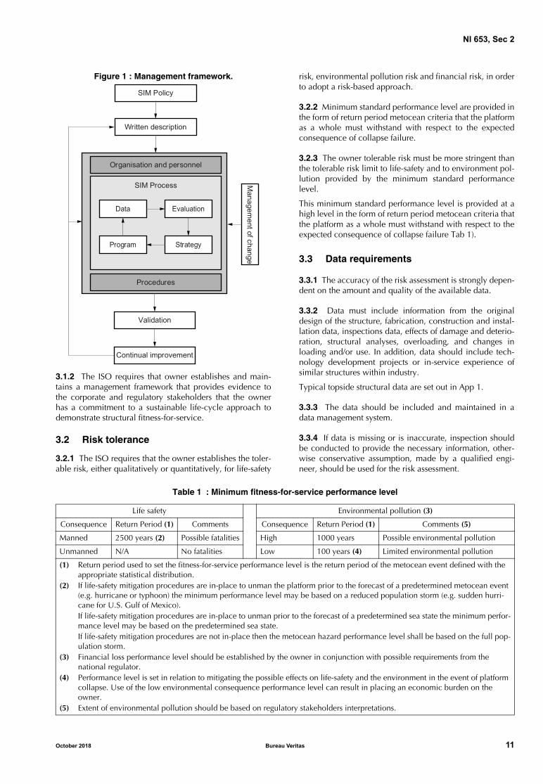
3.1.1 The management framework refers to the integratedsystems, work processes and documentation, which areused together with the SIM process to deliver structuralintegrity, including (see Fig 1):
• company policy, which sets out the intention and direc-tion of the owner with respect to SIM
• written description, which documents the processes andprocedures adopted by the owner for the managementof the structural integrity
• organization and personnel, which provides the report-ing lines, accountabilities, roles and responsibilities,and competencies required for the personnel
• SIM process, including all the activities to be set up fordemonstrating fit-for-service assets
• procedures, which are followed for implementation ofthe required activities
• MOC, which is used to identify and monitor changes
• validation, which is used to measure and verify perfor-mance against a set of defined metrics
• continual improvement, which reviews the process peri-odically and implement required changes.
10 Bureau Veritas October 2018
NI 653, Sec 2
Figure 1 : Management framework.
3.1.2 The ISO requires that owner establishes and main-tains a management framework that provides evidence tothe corporate and regulatory stakeholders that the ownerhas a commitment to a sustainable life-cycle approach todemonstrate structural fitness-for-service.
3.2 Risk tolerance
3.2.1 The ISO requires that the owner establishes the toler-able risk, either qualitatively or quantitatively, for life-safety
risk, environmental pollution risk and financial risk, in orderto adopt a risk-based approach.
3.2.2 Minimum standard performance level are provided inthe form of return period metocean criteria that the platformas a whole must withstand with respect to the expectedconsequence of collapse failure.
3.2.3 The owner tolerable risk must be more stringent thanthe tolerable risk limit to life-safety and to environment pol-lution provided by the minimum standard performancelevel.
This minimum standard performance level is provided at ahigh level in the form of return period metocean criteria thatthe platform as a whole must withstand with respect to theexpected consequence of collapse failure Tab 1).
3.3 Data requirements
3.3.1 The accuracy of the risk assessment is strongly depen-dent on the amount and quality of the available data.
3.3.2 Data must include information from the originaldesign of the structure, fabrication, construction and instal-lation data, inspections data, effects of damage and deterio-ration, structural analyses, overloading, and changes inloading and/or use. In addition, data should include tech-nology development projects or in-service experience ofsimilar structures within industry.
Typical topside structural data are set out in App 1.
3.3.3 The data should be included and maintained in adata management system.
3.3.4 If data is missing or is inaccurate, inspection shouldbe conducted to provide the necessary information, other-wise conservative assumption, made by a qualified engi-neer, should be used for the risk assessment.
Table 1 : Minimum fitness-for-service performance level
Managem
ent of change
Data Evaluation
Program Strategy
Organisation and personnel
Procedures
SIM Process
Validation
Continual improvement
SIM Policy
Written description
Life safety Environmental pollution (3)
Consequence Return Period (1) Comments Consequence Return Period (1) Comments (5)
Manned 2500 years (2) Possible fatalities High 1000 years Possible environmental pollution
Unmanned N/A No fatalities Low 100 years (4) Limited environmental pollution
(1) Return period used to set the fitness-for-service performance level is the return period of the metocean event defined with the appropriate statistical distribution.
(2) If life-safety mitigation procedures are in-place to unman the platform prior to the forecast of a predetermined metocean event (e.g. hurricane or typhoon) the minimum performance level may be based on a reduced population storm (e.g. sudden hurri-cane for U.S. Gulf of Mexico).If life-safety mitigation procedures are in-place to unman prior to the forecast of a predetermined sea state the minimum perfor-mance level may be based on the predetermined sea state.If life-safety mitigation procedures are not in-place then the metocean hazard performance level shall be based on the full pop-ulation storm.
(3) Financial loss performance level should be established by the owner in conjunction with possible requirements from the national regulator.
(4) Performance level is set in relation to mitigating the possible effects on life-safety and the environment in the event of platform collapse. Use of the low environmental consequence performance level can result in placing an economic burden on the owner.
(5) Extent of environmental pollution should be based on regulatory stakeholders interpretations.
October 2018 Bureau Veritas 11
NI 653, Sec 2
3.4 Structural integrity interface
3.4.1 The ISO requires that the topsides SIM addresses theinterfaces with other discipline-specific integrity programsand the SIM of third-party packages included on the topsides.
3.4.2 The structural integrity interfaces to be addressed canbe divided into:
• The interface between the topsides structures and otherelements managed by a different inspection regime e.g.the connections between the support structure and theequipment or topsides structures and the appurtenances
• The interface between the underwater inspection activi-ties and the above water inspection activities in whichthe topsides structures are included
The SIM of a topsides structure shall be consistent with theSIM process principles used for the supporting structure
• The interface between the topsides structure generalinspection regime and some structures under specificinspection requirements such as cranes, helideck, per-sonnel safety devices.
3.5 Inspection planning process
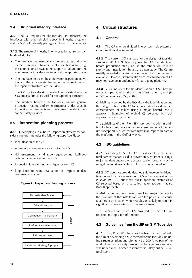
3.5.1 Developing a risk-based inspection strategy for top-sides structures includes the following steps (see Fig 2):
• identification of the CS
• setting of performance standards for the CS
• risk assessment, including consequence and likelihoodof failure evaluation, for each CS
• inspection intervals and technique for each CS
• loop back to refine evaluation as inspection databecomes available.
Figure 2 : Inspection planning process.
4 Critical structures
4.1 General
4.1.1 The CS may be divided into system, sub-system orcomponent level as required.
4.1.2 The current ISO standard for the design of topsidesstructures (ISO 19901-3) requires that CS be identifiedbefore production starts (i.e. in the fabrication yard orshortly after installation) by a walk-down study. The CS areusually recorded in a risk register, when such document isavailable. However, identification and categorization of CSmay not have been undertaken for an ageing platform.
4.1.3 Guidelines exist for the identification of CS. They areespecially provided by the ISO (ISO/DIS-19901-9) and JIPon SIM of topsides (MSL, 2004).
Guidelines provided by the ISO allow the identification andthe categorization of the CS to be undertaken based on theirconsequences of failure using a major hazard (MAH)approach. Examples of typical CS selected by suchapproach are also provided.
The guidelines of the JIP on SIM topsides include, in addi-tion to the consequence of failure, consideration of the fail-ure susceptibility assessed from historical inspection data ofthe platforms in the Gulf of Mexico.
4.2 ISO guidelines
4.2.1 According to ISO, the CS typically include the struc-tural barriers that are used to prevent an event from causing amajor incident and/or the structural barriers used to providemitigation and de-escalation in the event of an incident.
4.2.2 ISO does not provide detailed guidance on the identi-fication and the categorization of CS in the core text of theISO/DIS-19901-9, but it sets out in appendix examples ofCS selected based on a so-called major accident hazard(MAH) approach.
A MAH is defined as an event involving major damage tothe structure of the installation with the potential to causefatalities or an incident which results, or is likely to result, insignificant adverse effects on the environment.
The examples of typical CS provided by the ISO arerepeated in App 2 for information.
4.3 Guidelines from the JIP on SIM Topsides
4.3.1 This JIP on SIM Topsides has been carried out withthe aim of developing a SIM method for the topsides includ-ing structures, plant and piping (MSL, 2004). As part of thework done, a criticality ranking of the topsides structureswas undertaken in order to identify the safety-critical struc-tural items.
Hazards identification
Critical structure
Degradation mechanisms
Performance standards
Risk assessment
Inspection strategy & program
Update
12 Bureau Veritas October 2018

NI 653, Sec 2
The method used for this criticality ranking involved:
• a review of historical inspection data together withsome engineering assessment to define likelihood offailure of the structural items
• a classification of the consequence of this failure
• a criticality ranking based on the likelihood and theconsequence categorization.
4.3.2 The safety-critical structural items were identified asthose with higher criticality rank:
• For all platforms
- Deck plating / grating
- Helideck and safety nets
- Walkway grating and associated supporting struc-ture
- Handrails including posts
- Stair treads and stringers
- Swing ropes connections
- Access platforms and attachment points
- Risers supports/protectors.
• For platforms of exposure levels L-1 and L-2 only
- Secondary and tertiary structural framing
- Boat landings and fenders
- Pipework supports
- Conductors supports
- Service caissons supports.
4.4 General guidelines
4.4.1 The identification of the CS should take into accountboth the potential for failure and the severity of the corre-sponding consequence. Therefore, it should be based onconsiderations such as:
• the existence of structural components that are subjectto high loading
• the existence of structural components that are subjectto cyclic loading likely to lead to fatigue
• the history and future likelihood of corrosion and otherdefects
• the availability of alternative load paths where a struc-tural component can be defective (i.e. robustness andredundancy level)
• criticality of the structure to safety, production and theenvironment
4.4.2 In particular, structures protected by a passive or anactive fire protection system are part of the CS.
5 Performance Standards
5.1 General
5.1.1 DefinitionA performance standard is defined by the ISO, whichrepeats the reference definition provided by the Approvedcode of practice to the PFEER (HSE, 1995), as a statement,which can be expressed in qualitative or quantitative terms,
of the performance required from a system, item of equip-ment, person or procedure and which is used as the basisfor managing the hazard through the life-cycle of the instal-lation.
The ISO requires that performance standard be defined foreach of the identified CS, which will serve as a basis indefining the SIM strategy.
Thus, concerning CS, their performance standards are givenby the performance criteria they must achieve in order tofulfill their role in hazard management.
Specific performance standards are usually set for each ofthe phases of the life-cycle, from the phases of design, con-struction, installation and operation (including inspection,repair, and modification), to the phases of life extension anddecommissioning. For risk-based inspection planning, onlythe performance standards in the operational phase are ofinterest. In particular, the required performance standardswill serve has a basis to assess the likelihood of structuralfailure and to develop the risk-based inspection strategy.
Note 1: Specific performance standards are also established for theinspection and repair procedures, however, those aspects are notaddressed in this document.
5.1.2 General guidelines for setting effective performance standards
General guidelines for setting effective performance stan-dards are provided by the PFEER (HSE, 1995). A suitabledefinition for a performance standard should satisfy the fol-lowing conditions (Step Change in Safety, 2015):
• Scope and functionality of the system must bedescribed/defined
• Criteria must be specified for each safety critical compo-nent and these criteria should have a clearly defined(technical) basis
• Parameters must be measurable / auditable with definedacceptance criteria
• Measured parameters must provide evidence of the abil-ity of the component/system to meet its minimumrequirements and hence to prevent or limit the effect ofa Major Accident
Poorly defined performance standard may be ineffective oreven ignored, increasing the possibility of a Major Acci-dent, especially, if it is difficult to measure, if importantaspects/issues are missing, or if it is difficult to understand.
5.1.3 FARSI model for Performance Standards
The PFEER states that performance standards should bedefined with respect to functionality, survivability, reliabilityand availability requirements. The interaction with otherelements, the performance of which affects the performanceof the item under consideration, should also be taken intoaccount. Together, those types of requirement form the so-called FARSI (Functionality, Availability, Reliability, Surviv-ability and Interaction) model of performance standard, andallow a comprehensive list of parameters relevant for theperformance to be identified and acceptance criteria to bedecided for them in order to define in detail the perfor-mance requirement of the CS under consideration.
October 2018 Bureau Veritas 13

NI 653, Sec 2
The FARSI model shows the key requirements that are usu-ally included in a performance standard.
a) Functionality requirement defines what the structure isrequired to do e.g. to support equipment, to connectpipework to the structure.
b) Availability or Reliability requirement defines the abilityof the structure to fulfill its role whenever it is requiredto do so.
c) Survivability requirement defines how the structure willperform after an extreme event e.g. fire, explosion,dropped object, extreme weather, etc.
d) Interaction requirement defines the other safety criticalelements which are required to function in order for thestructure in question to function effectively.
For the CS, specific criteria can be established in the opera-tional phase for the functionality requirement. A measur-able functionality criterion for a CS may be expressed interms of the maximum allowable degradation that can betolerated. This may be derived from international standard,duty holder's degradation classification, industry guidelineor other best practice. It is likely that those criteria be lesssevere than the criteria used in the original design.
The other types of requirement are usually defined at thedesign phase, but they should be measured during the oper-ational phase to confirm compliance. For example, compli-ance with the minimum acceptable reliability and therobustness required to satisfy survivability criteria can bechecked, if required, in the operational phase using a struc-tural assessment.
5.2 Structural performance standard
5.2.1 GeneralNo generic requirement exists for setting a structural perfor-mance standard in the operational phase for topside struc-tures. In practice, those are given in the form of high-levelstatements regarding the required level of structural integritywithout specific requirements with respects to potentialhazards (HSE, 2009). Little work has been undertaken so faron the issue of performance standards for offshore structuresin the operational phase. The paper (Sharp, et al., 1999)shows how to better define performance standards for struc-tural components. The paper (Sharp, et al., 2008) describedthe background to developing Key Performance Indicators(KPIs) for offshore structures regarding the required perfor-mance standards. However, these have not been widelyapplied in the industry.
In practice, current design criteria in codes and standardscan provide a basis for setting performance standards fortopsides structures. However, the performance standardsrequired for an existing structure should be less restrictivethan those required at its design stage.
The structural performance standard should specify:• acceptance criteria for protective coating system, if
applicable• acceptance criteria for the condition of the structure
It should provide also means to assess the condition of thestructure in-service, especially the condition of a degradedstructure.
5.2.2 Acceptance criteria for the condition of protective coating system
The main objective of coatings is to constitute a barrierbetween the metal substrate and its aggressive environment,by providing:
• resistance from mechanical, chemical and biologicaldegradation
• dielectric insulation
• thermal insulation.
There are no standard acceptance criteria on the extent ofcoating degradation in-service. Most of the standardsresources available include acceptance criteria on the con-dition of the initial coating to be used for in-process inspec-tion. However, those acceptance criteria are so restrictive toensure a quasi-perfect sate of the initial coating that they arenot suitable for in-service inspection for which some dam-age may be tolerated; moreover, they involve someadvanced testing techniques that are rarely used for in-ser-vice inspection which usually uses visual examination.
It is reasonable to consider that the minimum performancerequired from coatings is the achievement of its main func-tion. Obviously, a coating system will no longer achieve itsfunction when the degradation, it is subjected to, leads tothe metal substrate being exposed to its aggressive environ-ment. The term “exposed” has a broader meaning here bycovering situation where coating is partly or totally removedor when the insulation properties of the coatings arealtered.
5.2.3 Acceptance criteria for the condition of the structure
The main function of a structure is to support and transmitthe loads occurring. Therefore, its strength must be largerthan those expected loads.
Acceptance criteria on the require strength of a degradedstructure along with assessment methods are provided byISO. The criteria based on the ultimate strength of a struc-ture which lead to the most accurate and less conservativeassessment are widely applied to jacket underwater struc-ture but no such application exists for topside structures.Therefore, criteria based on Design Level Method (DLM) aremore suitable to topside structures. However, those criteriaare component based, meaning that the most loaded struc-tural component drives the assessment. Moreover, the DLMcriteria usually includes safety factors. Thus, strictly apply-ing the DLM criteria is too restrictive for in-service assess-ment for which some level of damage may be tolerated.
Therefore, the acceptance criteria for the condition of a CSwill be given by an acceptable number of failed structuralcomponents in terms of DLM criteria. Moreover, the safetyfactors may be removed from the DLM criteria, if this isdeemed possible from operational experience, in order toreduce further the conservatism level of those criteria.
14 Bureau Veritas October 2018

NI 653, Sec 2
5.3 Assessment of the condition of a degraded coating system
5.3.1 General
The condition of degraded coating system can be assessedby the existing standard grading systems.
Details on those grading systems are provided in App 3.
5.3.2 Assessment of the condition of corrosion-protective coating
Standard grading systems for the assessment of the condi-tion of the corrosion protection coatings applied on top-sides structures are available from:
• the ISO
• the ASTM
• the SSPC.
Those standards provide pictorial guidelines for the visualassessment of the extent of corrosion on the surface ofpainted steel. Their rating scales are different but there is anequivalence relationship between them. The grading sys-tems are used to assess the overall condition of the coating.Localized damage on coatings are rather taken into accountfor the structural condition assessment.
The Minerals Management Service (MMS) of the UnitedStates Department of the Interior has also proposed a sim-plified A, B, C classification of the condition of corrosionprotection coatings. An improvement of the MMS gradingsystem has been suggested in the paper by Versowsky(2004), which defined corrosion assessment in terms ofcoatings deterioration and degree of substrate corrosion.
5.3.3 Assessment of the condition of PFP
The condition of the passive fire protection (PFP) can beassessed based on HSE guidelines. HSE provided advices onacceptance criteria for damaged PFP, based on the results ofa Joint Industry Project (JIP) that has examined the perfor-mance of cementitious and epoxy intumescent PFP (HSE,2007).
5.4 Assessment of the condition of a degraded structure
5.4.1 General
For in-service inspections, the condition of a degradedstructure is assessed by the extent of degradation of thestructure material, including corrosion wastage, fatiguecracks, dent depth, etc. The acceptable limit for extent ofdegradation of the structure itself is often given by anacceptable size of defect e.g. dents depth, thickness reduc-tion, crack length, etc. No standard rule was found specify-ing such limit, but in practice, those acceptable limits referto a proportion given in percentage of a characteristicdimension (e.g. diameter, thickness) of the structural com-ponent under consideration. Those limits could be relatedto a corresponding reduction in structural capacity. How-ever, their corresponding structural capacities are signifi-cantly conservative in comparison to the required minimumstructural capacity.
5.4.2 Assessment of the residual capacity of a degraded structure
When an accurate assessment of the residual structuralstrength of a degraded structure is required to directly assessthe structural performance against adverse conditions(extreme weather condition, extreme accidental loading orfatigue, whatever is applicable) there are means available toperform the computation. The existing guidelines include:
a) Residual strength:
Calibrated analytical formula for the residual staticstrength of a damaged or corroded structural memberare provided by the ISO 19902.
b) Remaining fatigue life:
The ISO like the API allow an analytical procedure inaccordance with ISO 19902 or API-RP-2A-WSD to beapplied to the structure in its as-is condition.
6 Risk Assessment
6.1 General
6.1.1 Risk assessment should be made for each topside CSbased on judgment regarding the likelihood of failure (CoF)and the consequence of failure (CoF).
6.1.2 The risk assessment is used mainly to define theinspection plans for all CS, but it can also be used as ascreening tool to select topside structural elements for moredetailed consideration, as and when more data is available.
6.2 Consequence of failure
6.2.1 The consequence of failure accounts for the impactin terms of life-safety, environment pollution and financialloss, should a failure occur.
6.2.2 ISO/DIS 19901-9 provides a consequence classifica-tion with respect to life-safety and environmental conse-quence only, leaving consideration of financial consequenceto the discretion of the owner or operator.
Three levels of consequence of failure are considered,namely:
• Possible life-safety incident
• Possible high environmental pollution incident
• Possible low environmental pollution incident.
6.3 Likelihood of failure
6.3.1 The likelihood of failure should account for:
• characteristics of hazard actions
• loading exposure (e.g. accidental loading)
• present structural condition
• potential degradation mechanisms
• service history
• structural redundancy and alternative load paths
6.3.2 The likelihood of failure can be determined by aqualitative, a semi-quantitative or a quantitative method.
October 2018 Bureau Veritas 15

NI 653, Sec 2
6.3.3 Qualitative methods use judgment, experience andknowledge on the topside structural aspects to categorizethe CS susceptibility to failure.
6.3.4 Semi-quantitative methods categorize a topside CSbased on a set of rules relative to its characteristic and con-dition data.
6.3.5 Quantitative methods compute explicit probabilitiesof failure based on code based Design Level Methods.
6.4 Risk ranking
6.4.1 The risk ranking usually uses consequence and likeli-hood categories and is presented in a risk matrix which showsthe distribution of the CS risks throughout the platform.
6.4.2 Different sizes of risk matrix may be used (e.g. 3 x 3,5 x 5, etc.), but the selected size should provide sufficientresolution to discriminate between the structural itemsassessed.
6.4.3 The risk categories on a risk matrix may take differentformats with symmetrical risk categories, where likelihoodand consequence have the same importance, or with asym-metrical risk categories where for example a higher weightis assigned to the consequence to reflect risk aversion.
Fig 3 shows typical examples of risk matrices.
7 Inspection Strategy
7.1 General
7.1.1 Inspection strategy & SIM policy
The SIM strategy should usually be consistent with theowner or operator SIM policy. The SIM policy refers to theoverall objective of the owner/operator that must beachieved by the activities and processes involved in theSIM. It varies between two extreme goals:
• The first extreme goal aims at avoiding that major repairis undertaken. It puts emphasis on early detection ofdamage, which leads to more frequent inspections with
preferably accurate inspection method especially NDE,while maintaining satisfactory structural integrity.
• The other extreme goal aims at reducing as much as pos-sible the inspections frequency, while maintaining satis-factory awareness of the structural condition. To achievethis enough robustness is given to the structure by suit-able design decision, including design margins, materialselection and structural component redundancy.
7.2 Scope
7.2.1 The overall inspection strategy includes many typesof inspections namely:
• Baseline inspection to determine the as-installed condi-tion of the structure
• Periodic or routine inspections to provide data on thepresent condition of the structure
• Special inspections that include:
- inspections of known anomaly or damage to moni-tor their extension or repair effectiveness
- inspections to verify the effectiveness of repairs tostructural components and appurtenances
- inspections to provide missing information for engi-neering assessment
- inspections prior conversion or life extension
- pre-decommissioning and pre-reuse inspections
• Unscheduled inspections following an extreme event oran accidental event.
7.2.2 The types of inspections, namely the baseline inspec-tion, the special inspections and the unscheduled inspec-tions, which are carried out once or under some conditions,should be implemented following the prescriptive require-ments provided by the ISO (ISO/DIS 19901-9).
The risk-based SIM should focus on the definition of theperiodic inspections strategy, which is the only inspectiontype that can be developed based on risk analysis results.However, the periodic inspection strategy should take intoaccount the results of the other types of inspection.
Figure 3 : Example of Risk Matrix Formats; (a) symmetrical, (b) asymmetrical.
1
2
3
4
5
A B C D E
1
2
3
4
5
A B C D E
(a) (b)
CoF category CoF category
LoF
cat
egor
y
LoF
cat
egor
y
16 Bureau Veritas October 2018

NI 653, Sec 2
7.3 Periodic inspection strategy
7.3.1 GeneralThe periodic inspection strategy includes the inspectioninterval and the inspection scope of work.
7.3.2 Risk-based inspection intervalThe risk-based intervals should account for the followingpossible deterioration/degradation mechanisms:
• coating breakdown
• corrosion
• fatigue
• fretting
• PFP degradation
• physical damage (e.g. dropped object)
• bolt loosening/failure
• other material degradation
• vibrations.
Indicative risk-based inspection intervals that may be usedfor setting the topsides CS are provided in Tab 2.
Table 2 : Indicative risk-based inspection intervals (ISO/DIS 19901-9)
7.3.3 Inspection scope of workThe type of inspection (i.e. GVI, CVI and/or NDE) to beused with the risk-based interval should be selected basedon the type of expected deterioration/degradation and thepresent known condition of the topsides CS. Usually GVIshould be carried out first. Then, close-up inspection i.e.CVI or NDE are performed where GVI cannot determine theextent of the damage.
Topsides elements selected for inspection can be based on:
• criticality of member or joint
• effect on global structural integrity
• consequence of failure
• degree of redundancy
• stress state complexity
• strength level
• degree of plastic straining
• exposure to fatigue loading
• service temperature
• service function of the element e.g. support of generatorand turbine, support of safety critical element.
Topsides components, which are commonly pre-selectedfor inspection, include:• main deck girders
• transitions to substructures• transition frames for concrete gravity base structures
• module trusses and support units• accommodation module
• derrick• bridges• flare booms and vent stacks
• cranes• helidecks
• lifeboats and other evacuation, escape and rescueequipment
• laydown areas• hull-deck connections
• changes to equipment weights and support locationpoints and deck load
• riser guards
• monorails
• lifting lug.
7.4 Particular considerations regarding the inspection planning of topsides structures
7.4.1 GeneralSpecific features related to the inspection of topside struc-tures should be addressed in planning the inspection,namely:
• the inspection interfaces• inspection required for non-structural safety critical ele-
ments• the not inspectable structural components.
7.4.2 Inspection interfacesThe inspection of the topsides structures usually interfaceswith many other inspection activities and production activi-ties.
a) There is an interface between the inspection of the top-side structures and the inspection of the substructure.Those parts of the platform structure usually have spe-cific inspection strategy and their respective inspectionscopes of work are executed separately. However, espe-cially for the fixed platforms, the damage observed ontopsides structures and splash zone structures can trig-ger inspection of the underwater structure to look forpossible impact damage from falling debris from theabove water structure.
b) There is an interface between the actual risk-basedinspection strategy and specific inspection requirementfor some topside structures e.g. crane, helideck, appur-tenances, personnel safety devices. For example, theinspection of cranes is covered by the international stan-dards ISO 4309, API-RP-2D and FEM (European Materi-als Handling Federation). Inspections of helidecks areusually performed for helideck certification. Appurte-nances e.g. risers, pipelines have specific standards
CoF
Possible life-safety incident
1 to 2 years
Annual Six monthly
Possible high environmental pollution incident
1 to 3 years
1 to 2 years
Annual
Possible low envi-ronmental pollu-tion incident
1 to 5 years
1 to 5 years
1 to 2 years
Low Medium High
LoF
October 2018 Bureau Veritas 17
NI 653, Sec 2
addressing their inspection requirements e.g. ISO16440, API 570. Inspection requirement are providedfor attachment tie-down in API and for escape routes inAPI 54. However, when the actual risk-based inspectionrequirement is in competition with specific inspectionrequirement applicable to a given structure, the lattershould be applied, unless otherwise specified, but thisshould be clearly justified.
c) The inspection of the connections between the equip-ment or pipework and their support structures isrequired, both in the inspection of the support structureand in the inspection of the equipment or pipework.Therefore, in defining the inspection scope of work, oneshould be aware of the possible inspection of sup-port/equipment connections already carried out as partof the equipment inspection program, to take intoaccount their results or not to perform unnecessaryinspection.
d) There is an interface between the actual inspection pro-gram for topside structure and inspection activities per-formed by other disciplines. Therefore, there may be anopportunity to perform topside structure inspectiontogether with another inspection activity. For example, atrained visual inspector, who is certified for survey ofboth structures and process facilities, could inspect boththe structure and the exterior of the process facilities.
e) The inspection activity on some topsides structures, e.g.flare boom, heat shield, usually require platform shut-down. Therefore, the expected downtime should beconsidered in planning those inspections so as toreduce production loss if necessary.
7.4.3 Inspection required for non-structural safety critical elements
ISO requires that supports for equipment, e.g. safety criticalcommunications, electrical and firewater systems, etc, beinspected as part of the inspection of the topsides structures.In fact, even if they are not of a structural nature, they arelikely to be safety critical. In particular, attention should bepaid to their connections to the platform structure, whichcan be affected by the effects of accidental loading, includ-ing strong vibration.
7.4.4 Not inspectable structural components
Some structural joints are classified as not inspectable espe-cially because they are hidden due to their location. Theyare usually designed with larger fatigue design safety factorto ensure higher strength against degradation mechanism.Such structural components are normally excluded from theinspection scope of work. However, some information ontheir likely condition can be deduced from an externalinspection.
7.5 Maintenance strategy
7.5.1 ISO recommends implementing structural mainte-nance strategy, in complement to the inspection plan, inorder to mitigate possible significant degradation mode thatcan reduce the structural strength of critical structures. Thiswill result in a reduction of the inspection scope of work.
7.5.2 The maintenance strategy should include:
• protective coating systems and fabric maintenance pro-gram
• grating replacement schedule.
7.5.3 The maintenance tasks and schedules should bedeveloped based on good practices, equipment vendorguidelines and owner risk tolerance criteria.
7.5.4 Risk-based coating maintenance program may bedeveloped to optimize the maintenance of the protectivecoatings, which is resource demanding and costly (Axelsen,et. al., 2009).
8 Inspection Program
8.1 General
8.1.1 Inspection program should establish specificationsfor inspection activities and establish procedures for qualityassurance, quality control, and data validation.
8.1.2 Inspection specification should, as a minimum,include:
• anomaly reporting requirements
• NDE technician qualifications
• notification requirements following discovery of ananomaly
• measurement procedures (e.g. dents, bows, holes)
• sensors and instrumentation
• reporting formats and procedures
• photography and video recording procedures.
8.2 Inspection specifications
8.2.1 General visual inspectionGVI shall be performed to determine the condition of themembers, joints, or components selected for inspection.
If above water damage is detected, a record of the damageshould be made to allow engineering personnel to deter-mine if repairs or further inspection (e.g. NDE) are required.
Damage records should include measurements, photo-graphic documentation, and drawings. If the above watersurvey indicates that underwater damage could haveoccurred (e.g. a missing boat landing or unrecorded dam-age exists), an underwater inspection should be performedas soon as conditions permit.
8.2.2 Coating survey (including PFP)Coating survey shall be performed to detect deterioratingcoating systems and corrosion. The survey should report thetype of coating systems for the components inspected (i.e.cladding or elastomer on the splash zone members andjacket legs, paint on the conductors), and record the loca-tions and extent of coating deterioration.
8.2.3 Attachment tie-down pointsIf specified in the topsides inspection scope of work, awalk-down survey to assess the vulnerability of personnelsafety equipment and supports to damage from shock load-
18 Bureau Veritas October 2018

NI 653, Sec 2
ing and strong vibration induced from extreme or abnormalmetocean or seismic events or accidental loadings shall beperformed.
Walk-down is primarily a visual inspection and may be per-formed to coincide with the routine topsides inspection.The support can be permanent or temporary and the datashould be recorded to allow engineering personnel to eval-uate the ability of the tie-down to resist lateral loads.
8.2.4 Escape routesDuring the topsides inspection a visual survey of the per-sonnel escape routes shall be performed. Escape routesconsist of open decks, walkways, stairs, and landings. Theroutes should be established and surveyed to confirm clearaccess to the escape routes is provided from locations onthe structure. Crane transfer carriers and connectionsshould be examined for signs of damage or deterioration.
8.2.5 Deck elevation surveyFor fixed platform in operational areas of known or sus-pected subsidence, the topsides inspection shall include asurvey of the gap between the cellar deck bottom of steeland the mean water level. For other areas, the deck eleva-tion should be measured on a periodic basis to provide up-to-date and accurate information. Measurements should berecorded against the time of measurement to allow lateragreement with tidal information or changes. Suspectedsubsidence or differential settlement of the structure shouldbe recorded.
8.2.6 Close visual weld/joint surveyIf specified in the inspection scope of work, a close visualweld/joint survey consisting of a visual examination of theselected weld/joint in the jacket shall be performed. Theclose visual weld/joint survey should be used to detect and
size visual cracks in or adjacent to the weld and confirm theextent of corrosion of the steel surface and areas adjacent tothe weld.
8.2.7 Damage surveyIf damage is found during the visual survey, a follow-up sur-vey should be performed to obtain data for the damageevaluation. The survey should identify the location andshould include dimensional measurements to measure suchquantities as damage size and geometry, member out-of-straightness, crack length and depth, corrosion pit size, etc.The survey should be extended to inspection for collateraldamage (e.g. a heavily dent-bowed member, bulging orbuckled could have cracks at the member ends).
8.2.8 Bolted connection inspectionsBolt tightness checks should be performed to confirm thatthe bolt nuts used for connecting and attaching topsidescomponents are not loose.Note 1: It is also important that best industrial practices be appliedto ensure the tightness of the bolted connection since former tech-niques (e.g. flogging spanners) have proven to increase likelihoodof hydrocarbon releases and/or joint failures.
Some best industrial practices are set out in the guideline “Mechan-ical Joint Integrity - Competence Guidance” published by the UKorganization “Step Change in Safety”.
8.2.9 Aerial surveysUnmanned aerial vehicles (UAVs) may be used for high-altitude inspections on structures (e.g. flare booms and der-rick). However, such surveys should be verified and certi-fied for reliability and fitness-for-purpose. Availablerecommendations of the Society on the use of RemoteInspection Techniques (RIT) are provided in App 1 ofNR533 “Approval of Service Suppliers”.
October 2018 Bureau Veritas 19

NI 653, Sec 3
SECTION 3 RISK-BASED INSPECTION PLANNING METHOD
1 General
1.1 Purpose
1.1.1 The purpose of the method described in this Sectionis to perform risk assessment and develop inspection strat-egy for offshore topsides structures.
1.1.2 The risk assessment and the resulting risk-basedinspection strategy are focused on the structural systems,structural sub-systems and structural components that havebeen identified as critical for the safety, the environmentand the production.
1.2 Scope of application
1.2.1 The risk-based inspection (RBI) method is applicableto:
• the above water structures of fixed platforms includingthe below deck structure (i.e. splashzone) and the top-sides structures on the deck
• the topsides structures on the deck of floating units
• the bridges
• and the connecting structures.
1.2.2 The risk assessment developed as part of the methodcan be carried out on structural components or on groups ofstructural components.
1.2.3 The structural components are classified as follows:
• structural member types
- cylindrical tubular members
- members with non-cylindrical sections e.g. plates,plate girders, box girders, profiles, stiffened platestructures and stressed skin structures.
• connections
- welded connections between members
- bolted connections.
- castings
- forging.
1.2.4 Relevant groups of structural components include:
• groups of structural components that fall under typicalcategories, for example:
- primary, secondary and tertiary structures
- deck plates, gratings and handrails
- means of access and associated handrails and stairs
- ancillary structures
- foundations of safety critical elements.
• groups of structural components that provide specificstructural function to equipment and appurtenances, forexample:
- equipment connections
- pipework connections
- risers / conductors guides
- protection frames
- …
• groups of structural components that belong to specificareas worth being considered as a whole in SIM analy-sis, for example:
- main and secondary escape routes
- muster area
- …
1.2.5 The method includes also in the scope the connec-tions to the platform structure of non-structural elementssuch as the supports for equipment e.g. safety critical com-munications, electrical and firewater systems, etc. They areincluded following ISO recommendation since they arelikely to be safety-critical and can be affected by the effectsof accidental loading, including strong vibration.
2 Implementation
2.1 General
2.1.1 The process for implementing the RBI method con-tains three main steps:
• an initial RBI workshop
• the risk assessment
• the definition of the inspection strategy.
Since risk is dynamic (i.e. changes with time), it is importantto maintain and update an RBI assessment to ensure that themost recent inspection, process, and maintenance informa-tion is included.
2.2 RBI workshop
2.2.1 GeneralAn RBI workshop must be conducted at the beginning of anRBI project for planning the RBI assessment.
This workshop should allow the following tasks to be car-ried out:
• an RBI training
• the organization, the role and responsibilities of the RBIteam
• the achievement of an agreement on key elements ofthe RBI.
20 Bureau Veritas October 2018

NI 653, Sec 3
2.2.2 RBI trainingA training on the RBI method should be deliver as part ofthe initial RBI workshop to the stakeholders likely to beinvolved such as inspection personnel, structural engineers,operating personnel and other stakeholders involved in thedecisions on managing risks.
The purpose of this training is to show the audience theconcepts and principles embedded in the RBI method andto help them understand the risk assessment process inorder for them to be able to appraise and to accept the RBIresults.
2.2.3 RBI teamThe RBI method involves a multi-disciplined approachsince it requires data gathering from many sources, manyspecialized analyses and risk-management decision-mak-ing. Therefore, the team members should have skills andbackgrounds in the following disciplines:
• Risk analysis
• Offshore structural engineering
• Deterioration/degradation mechanisms and failure modes
• Offshore maintenance and inspection techniques andtechnologies
• Material, corrosion and coating engineering
• Environmental, safety and health systems and regulations
• Operations.
It is essential to have a team leader whose main functionsshould be:
• to coordinate the team members
• to facilitate the RBI meetings that will take place duringthe RBI project
• to ensure that the study is properly conducted
• to integrate the inputs and outputs into the final RBIreport.
It is essential that a representative of the Society be involvedfor the RBI assessment of topsides structures of floating unitswithin the class rule.
The other team members should participate and contributeto the RBI analysis to the extent of their skills. They shouldcarry out the following tasks with respect to their area ofcompetence:
• providing data/information required
• verifying/checking soundness of data and assumptions
• assessing the structural condition
• assessing the risk level
• verifying/checking adequacy of the resulting inspectionplan.
As part of the RBI team make-up, some knowledgeable peo-ple may be identified to serve as advisors. They are not partof the core RBI team, but they may be consulted to providerecommendations on ways to address specific issues relatedto their area of expertise.
RBI assessment requires also the commitment and the coop-eration of the operating organization. It is essential that theOffshore Installation Manager (OIM) be involved.
2.2.4 Key elements of the RBI analysis
As part of the initial RBI workshop it is important that anagreement be achieved among all the stakeholders on thefollowing key elements of the RBI analysis:
• the objective of the RBI assessment
• the risk acceptance criteria / the risk matrix format
• the CS selected for the RBI assessment
• the performance standards to be applied
• the data requirements
• the type or level of risk assessment method to be used
• the time and resource required
• the deliverables
• the period of validity of the RBI assessment and when itshould be updated
• the applicable codes and standards.
2.3 Risk assessment
2.3.1 General
The risk assessment process involves the following steps:
• data collection
• risk rating
The risk assessment may start with an initial screening of thewhole structure to select the structural items on which therisk assessment will be focused.
2.3.2 Initial screening
If the scope of the RBI assessment is the entire topsidesstructure, a screening of all the structural items will be con-ducted first to identify those structural items that are mostimportant in terms of risk. Those ones will then be selectedfor the application of the RBI assessment so that time andresources are more effectively used.
The initial screening provides also insight about the level ofassessment that may be required for the selected structuralitems.
The initial screening can be performed using a simplifiedqualitative risk assessment or through HAZID sessions.
2.3.3 Data collection
Typical data required for the risk assessment include:
• initial design criteria
• robustness/redundancy level
• degree of uncertainty on the as-installed condition
• materials of construction
• structural strength data (e.g. computed ultimate strengthand fatigue strength)
• coating, cladding, and insulation data
• inspection, repair and replacement records
• damage mechanisms, rates, and severity
October 2018 Bureau Veritas 21

NI 653, Sec 3
• data on the conditions in the vicinity of the structure,including:- fluids inventory- temperature- operations- drainage systems- safety systems- detection systems- personnel density
• business interruption• repair• replacement• environmental remediation.
Those data may be gathered from various sources, includ-ing:• design, construction and installation records
- reports- drawings- engineering specification sheets- codes and standards used- mill certificates- equipment and appurtenances layout- installation logs
• structural assessment reports/drawings• inspection records• operating logs• MOC records• industry specific structural failure data• industry databases• hazards analysis report e.g. QRA studies• anomaly register• risk register.
If a required data is missing or inaccurate, survey should beconducted to collect the required information, otherwiseconservative assumption should be taken during the riskassessment.
2.3.4 Risk ratingThe RBI method of this document applies the risk assess-ment method described in Article [3].
2.4 Inspection strategy
2.4.1 GeneralAn inspection plan must be developed for each structuralitem selected for the RBI assessment.
The inspection strategy must cover the service lifetime ofthe offshore unit and must be reviewed periodicallythroughout this lifetime to identify whether changes arerequired and apply them.
It must specify:• the inspection interval or inspection schedule• the inspection technique• the inspection coverage when close-up inspection is
required on a group of structural components
The risk-based inspection strategy to be used by default isset out in Article [4].
The inspection strategy can be modified by consideration ofthe regulation requirements and the operational feasibility.Therefore, it is important that operational team members beinvolved at this stage to demonstrate that the final inspec-tion strategy conforms to regional regulations and is work-able based on location infrastructures and capabilities.
2.4.2 Inspection intervalThe inspection interval should be based on standards rec-ommended risk-based inspection intervals or on generalindustry experience. If specific inspection intervals areselected, technical justification should be provided to sup-port the choice made. This technical justification may bebased on consideration of the possible degradation mecha-nisms, the deterioration rate and the detection capability ofthe selected inspection method.
2.4.3 Inspection techniqueThe inspection technique should be selected by a qualifiedpersonnel based on the type and size of the expected deteri-oration.
The Society feedback and agreement is required for floatingunit within the class rule.
2.4.4 Inspection coverageThe inspection coverage may be given by:
a) A percentage of structural details to inspect so as tohave representative condition data of the structure.
This representative percentage should be based on bestindustry practice and standards; otherwise technical jus-tification of the choice made should be provided.
b) A selection of location where the likelihood of damageis higher.
Those location should include:
• area of suspected or known damage from the servicehistory or from industry experience
• area with higher stresses or lower fatigue life
Those location may be selected based on a local riskranking of the structure’s components.
2.5 RBI updating
2.5.1 GeneralIt is important that an effective MOC process be in placethat identifies when a RBI updating is necessary.
A frequency at which the RBI assessment is to be reviewedmust be defined and agreed at the initial set up of the RBI.
2.5.2 When to conduct an RBI updatingAn RBI updating is required:
• after significant changes in process conditions, damagemechanisms/rates/severities or RBI premises
• after a set period of time (e.g. period of validity of thecurrent inspection plan, an establish maximum timeperiod for the RBI updating)
• After implementation of risk mitigation strategies.
22 Bureau Veritas October 2018

NI 653, Sec 3
3 Risk Assessment Method
3.1 General
3.1.1 The risk assessment is to be carried out for each of theidentified CS.
3.1.2 The likelihood of failure is assessed by a rule-basedscoring method. The scoring rules should be set up accord-ing to the performance standard required by the owner/operator.
Structural assessment results if available could allowimprovement of the likelihood scoring.
3.1.3 The consequence of failure is given by an exposurecategory with respect to the impact in terms of life-safety,environment pollution and financial loss.
3.2 Performance standard
3.2.1 GeneralAn example of a minimum performance requirement for agiven CS in operational phase is provided here-below. It isgiven in terms of a minimum acceptable degraded condi-tion of the structure and of the protective coating system(e.g. corrosion protection coating, PFP) eventually appliedon that structure.
Any specific performance standard defined by the ownermust ensure at least the same safety level as this minimumperformance standard.
3.2.2 Acceptance criteria for the condition of corrosion-protective coating systems
The corrosion coating systems are required to be main-tained in a FAIR condition, corrosion coating conditionbeing defined as follows:
• GOOD condition with only minor spot rusting
• FAIR condition with local breakdown at edges of stiffen-ers and weld Connections and/or light rusting over 20%or more of areas under consideration, but less than asdefined for POOR condition
• POOR condition with general breakdown of coatingover 20% or more of areas or hard scale at 10% or moreof areas under consideration.
More detailed ranking system of the corrosion-protectivecoating condition could be found in App 3.
3.2.3 Acceptance criteria for the condition of PFPPFP condition is required not to reach severity level 2according the classification of PFP condition provided inApp 3.
3.2.4 Acceptance criteria for the condition of the structure
The method of this document proposes the following mini-mum criteria with respect to the strength of the CS to beapplied in operation:
• The strengths of the primary structural components,which are part of the CS, are required to satisfy the DLMcomponent-based criteria.
• The secondary and tertiary structural components of theCS, when it is a structural system or group of structuralcomponents, are taken together and the proportion ofcomponents the strength of which don't comply withthe DLM criteria is required to be less than 10%
• The degraded strengths of the failed secondary or ter-tiary structural components are required to be still largerthan 75% of the allowable strength specified by theDLM criteria.
However, the DLM criteria can be reduced by removing thesafety factors and/or by using mean rather than nominalyield stress, but this should be justified from the operationalexperience.
The 90% of secondary or tertiary structural components isarbitrarily chosen, the most important being the integrity ofthe primary structural components which mainly bear theloadings, while the number of damaged secondary or ter-tiary structural component is indicative of a degradationprocess going on, which may affect more structural compo-nents including primary members.
The condition of the structure can be assessed qualitativelyusing a relevant classification of the extent of degradationon the structure given by the size or/and the number ofdefects. It can be assessed quantitatively also by the residualstrength of the degraded structure.
3.3 Likelihood of failure
3.3.1 General
The assessment process consists in, first assigning a score tolikelihood using the following formula:
where:
Si : Partial scores assigned to influencing factors
wi : Weights to account for how sensitive is theoverall likelihood to the factors.
Then, a likelihood category is allocated to the CS underconsideration with respect to the range in which the overallscore lies.
The ranges for the likelihood categories and the weights ofthe influencing factors are calibrated using an arbitrary setof representative structures the likelihood level of which areassumed based on expertise and experience.
3.3.2 Influencing factors
The factors which affect the likelihood are divided as follows:
• Baseline condition
- Design practice
- Robustness
- Extent of fabrication and installation inspections
- Ultimate strength
- Fatigue strength.
S wi Sii
=
October 2018 Bureau Veritas 23
NI 653, Sec 3
• Current condition- Design condition deviation- Extent of degradation of the protective coating sys-
tem (e.g. corrosion protection coating, PFP)- Extent of damage on the structure- Level of surface corrosion- Penalty factor accounting for compliance with due
inspection year- Penalty factor accounting for compliance with
required inspection method.• Degradation exposure
- fatigue sensitivity- Damage susceptibility- Affected by heat- Subjected to low temperature- Severity of the corrosion environment- Potential for internal corrosion.
• Modifications and upgrades- Weight change due to addition or deletion of equip-
ment- Structural modification- Change to operational procedures- Change to regulations, standards and specifications.
3.3.3 Design practiceThe method assumes that the topside structures weredesigned in conformance with the appropriate internationalstandard especially the ISO 19901-3. The design require-ments of the ISO 19901-3 include:• Deck elevation requirements for topsides on fixed plat-
forms and green water requirements for topsides onfloating structures
• Design criteria for structural components• Appropriate design situations and load cases to be consid-
ered for structural systems such as flare tower, helideck,crane support, derrick, bridges and bridges bearings, anti-vibration mounting, walkways, laydown areas, mainte-nance areas, muster areas and lifeboat stations
• Specific requirements for corrosion protection system,fire protection system, deck drainage system
• Requirements for the relevance of system interfaceassumptions
• Requirement to correctly take into account the actiondue to drilling operation on safety critical elements andprotective coatings
• Requirements for structure sited near heat producingfacilities e.g. flare and exhaust dust
• Material selection requirement with reference to therequirements laid out in the ISO 19902.
The compliance of the design practice with the appropriateinternational standard e.g. ISO 19901-3 can be assessedusing checklists based upon the requirements laid out in thestandard.
In case of none compliance with any of the design criteria,expert analysis should be undertaken to determine how thisincreases the baseline likelihood of failure of the affectedstructures.
3.3.4 Robustness
The robustness is to be considered at the design stage. Therequirement related to robustness for the design of topsidestructures implies that the structural integrity in damagedstate is sufficient to allow a process system close-down, or asafe evacuation, or both. Robustness is preferably achievedby an appropriate bracing pattern that provides alternativeload paths.
The level of robustness of the topside structural items isassessed qualitatively based on expert judgment.
3.3.5 Extent of fabrication and installation inspections
The method assumes that in-process inspections were per-formed in conformance with the appropriate internationalstandards (e.g. ISO, ASTM and NACE typically for corrosionprotection coatings). Many standards are involved in thespecifications for in-process inspections, each one address-ing a typical issue in the process. They usually provide:
• Requirements on the inspections to be conductedthrough the coating application process, including:
- Specifications and test methods for coating material
- Recommendations for the inspection of the pre-existing condition of the surface of steel substrates
- Recommendations for the inspection of the surfacepreparation on steel substrates
- Recommendation for the inspection of mixing, thin-ning and coating application
- Specifications and test methods for the performanceof the coating system after application
• NDT inspection requirement for welding including mini-mum extent of weld inspection with respect to the type ofstructural component and the NDT technique (ISO19902).
The compliance of the in-process inspections with the appro-priate international standards can be assessed using check-lists based upon the requirements laid out in the standards.
In case of none compliance with any of the standards'requirements, expert analysis should be undertaken todetermine how this increases the baseline likelihood of fail-ure of the affected structures.
3.3.6 Ultimate strength
This factor accounts for the ultimate capacity obtained froma structural analysis especially the last structural assessmentof the topside structure under consideration.
The ultimate strength of a CS is given by the unity check(UC) value. If the CS is a structural component (e.g. primarymember) its UC value is to be used to define the staticstrength, while if the CS is a structural system or a group ofstructures a percentile of the UC of its structural componentsis used to define the static strength in order to conform to theprinciple adopted for defining structural performance stan-dard. By default, the 90%-percentile is used.
24 Bureau Veritas October 2018

NI 653, Sec 3
3.3.7 Fatigue damage ratioThis factor accounts for the likelihood of fatigue crackoccurrence on the structural components especially weldedtubular joints.If the CS is a structural component (e.g. primary member) itsfatigue damage ratio value is to be used, while if the CS is astructural system or a group of structures a percentile of thefatigue damage ratio of its structural components is used, inorder to conform to the principle adopted for defining struc-tural performance standard. By default, the 90%-percentileis used.
3.3.8 Design condition deviationThis factor accounts for deviation of the condition of astructural component from that used for the design e.g.change in loading.This factor is assessed in terms of how large the deviation is.However, if the deviation is larger beyond an acceptablelimit, a structural assessment must be considered to checkfitness-for-service before proceeding with the analysis.
3.3.9 Extent of degradation of its protective coating system
This factor accounts for the extent of degradation foundfrom previous inspections. The extent of detected degradation is rated qualitatively e.g.intact, minor, severe,… The criteria defining the qualitativeextent should be set up according to the performance stan-dard required by the operator or owner.
3.3.10 Extent of damage on the structureThis factor accounts for the extent of structural damagefound from previous inspections. The extent of detecteddamage is rated qualitatively e.g. intact, minor, severe,…The criteria defining the qualitative extent should be set upaccording to the performance standard required by theoperator or owner.
3.3.11 Level of surface corrosionThis factor accounts for the corrosion wastage found on thestructure from previous inspections. The extent of surfacecorrosion is rated qualitatively e.g. no, minor, severe,… Thecriteria defining the qualitative extent should be set upaccording to the performance standard required by theoperator or owner.
3.3.12 Penalty factor accounting for compliance with due inspection year
This factor penalizes structural components which have notbeen inspected at the time required by the current inspec-tion plan and are still not inspected at the time of the riskassessment. This induces uncertainty on the current condi-tion of the structural components under consideration.
3.3.13 Penalty factor accounting for compliance with the required inspection method
This factor accounts for the accuracy of the inspectionmethod used.
3.3.14 Degradation exposureAll the degradation exposure factors (namely: fatigue sensi-tivity, damage susceptibility (e.g. mechanical handling way,laydown area, drop object...), affected by heat, subjected to
low temperature, severity of the corrosion environment,potential for internal corrosion) have the same format ofscoring rule. The scoring rule is defined in terms of whetherthe structural component is exposed to a degradation mech-anism, and whether a measure is in place to reduce theidentified degradation susceptibility.
3.3.15 Modifications and upgrades
This scoring rule reflects how the loads and potential haz-ards on the structure, the capacity of the structure and thestructural performance criteria are affected by the modifica-tions and upgrades carried out and their resulting influenceon the LoF.
3.4 Calibration process of the LoF scoring
3.4.1 General
A calibration process allows computing the weights of theinfluencing factors and the limits values of the ranges of thescores for the LoF categories.
In the current scoring process the range of the scores for thelikelihood category are fixed. Therefore, the calibration ofthe scoring formula consists in finding the weight valuesthat yield a result as close as possible to the expected LoFcategory.
The calibration process involves the following steps:
a) select influencing factors with larger importance for thelikelihood
b) generate a sample of structural data with respect to theparameters of the selected influencing factors
c) assign a LoF category to each one of the sample databased on expertise and experience
d) compute the weights of the selected factors by a leastsquare method so that the scoring formula providesresults as close as possible to the expected ones
e) validate the computed weight on a generated sample setinvolving all the structural integrity parameters.
3.4.2 Selection of factors for the calibration
Factors with larger importance are selected. They shouldallow a likelihood category corresponding to typical valuesof their respective parameters to be perceived. These arefactors for which simple rules can be defined on how theyinfluence the likelihood. For example, such factor maymove the structural component from one category toanother when its parameters are changed from the lowest tothe highest value.
Several important factors may be considered having thesame weight. In those cases, only one of them should beselected for the calibration, and then its computed weightwill be allocated to the others.
The weights of the remaining factors with smaller impor-tance will be allocated marginal values in comparison tolarger importance factors selected for the calibration. Theycan be assigned a fraction of the lowest computed weightso that they could not allow a structural component tomove from one category to another over the full range oftheir variation.
October 2018 Bureau Veritas 25

NI 653, Sec 3
3.4.3 Calibration set
The sample set of structural component for the calibration isgiven by a certain number of relevant combinations of theparameters of the selected influencing factors.
3.4.4 Expected category allocation
The sample of structural component defined for the calibra-tion is submitted to knowledgeable people so they can pro-vide a likelihood category from their expertise andexperience. Thus, the provided categories will be all themore suitable as their level of expertise is higher.
Moreover, specific requirements from the operator or ownerwith respect to his risk perception or risk aversion can betaken into account in the allocation of an expected likeli-hood category. In this case, it must be ensured that the min-imum acceptable performance is still met.
3.4.5 Weight computation
The weights of the selected factors are computed by a leastsquare method so that the scoring formula provides resultsas close as possible to the expected ones. However, it is rec-ommended to ensure that when the scoring provides likeli-hood different from expected, it should still be conservative.
Those remaining factors which are considered of similarimportance as one of the selected one are allocated the cor-responding same weight. The other factors with smallerimportance are allocated marginal values with respect tolowest weight of the factors selected for the calibration.
3.4.6 Validation
A sample set is generated involving preferably all the struc-tural integrity parameters. Their respective LoF category iscomputed with the obtained scoring formula. Those com-puted LoF are then checked by knowledgeable people inorder to validate the scoring formula.
3.5 Consequence of failure
3.5.1 General
The consequence of failure accounts for the impact in termsof life-safety, environment pollution and financial loss.
3.5.2 Life-Safety consequence
The life-safety consequence level depends on whether off-shore personnel are exposed or not when a structural failureoccurs.
The factors which affect the life-safety consequence are:
• the manning status of the platform (only for fixed platforms)
• the possibility of fatalities or injuries in case of structuralfailure e.g. failure of walkways
• the possibility of structural failure escalating to hydro-carbon blast and fire
• the possibility of structural failure causing release oftoxic smoke or gas.
3.5.3 Environmental consequence
The environmental consequence level depends on theexpected volume of hydrocarbon released as the result ofthe structural failure.
The factors which affect the environmental consequence are:
• the platform type (only for fixed platform) includingdrilling and/or production, storage platforms
• the capacity of the processing and / or storage facilitiessupported by the platform
• the proximity of the failing structure to major process orstorage equipment or to major pipework
• mitigation measure that is in place to reduce the envi-ronmental consequence.
3.5.4 Financial consequence
The financial consequence level depends on the expectedfinancial loss as the result of the structural failure and/orrepair.
The factors which affect the financial consequence are:
• the structural importance
• accessibility for repair
• additional repair cost e.g. logistic costs.
3.6 Risk ranking
3.6.1 The risk ranking uses by default a 5 x 5 asymmetricalmatrix (see Fig 1).
Figure 1 : Default risk matrix format.
3.6.2 Owner or operator specific risk matrix is also applica-ble provided that, on one hand, the likelihood scoringmethod is calibrated against it; on the other hand the conse-quence is categorized according to it.
4 Inspection Strategy
4.1 Default risk-based inspection intervals
4.1.1 The method proposes using by default risk-basedinspection intervals not larger than those set out in Fig 2.
5
4
3
2
1
1 2 3 4 5
Consequence
Like
lihoo
d
IV
III
II
I
I I
II
II
III
III
III
III
III
III
IV IV V V
V
V
IV IV
IV
IV
IV
26 Bureau Veritas October 2018

NI 653, Sec 3
Figure 2 : Maximum risk-based inspection intervals [in years] based on ISO.
4.2 Default inspection scope of work
4.2.1 The method of this document recommends that thetype of inspection technique be selected with respect to therisk level as shown on Fig 3.
Figure 3 : Minimum requirement for the inspection method to be selected.
4.3 Specific inspection plan
4.3.1 Owner specific risk-based inspection intervals andscope of work must achieve at least the same level of safetythan the default risk-based inspection plan.
5 Inspection program
5.1 General
5.1.1 The implementation of the inspection program isunder the responsibility of the owner or operator who is incharge of conducting the detailed inspection work scope tocomplete the activities defined in the inspection strategy.Therefore, this article is not part of the RBI method devel-oped by the Society.
5.1.2 This article is provided for information in order todraw attention to important requirements for the implemen-tation of the inspection program, which may be useful when
the Society is required to appraise the inspection programor is involved in its specifications.
5.1.3 The inspection program contains two main elements:
• its specification
• its execution
5.2 Specification of the inspection program
5.2.1 Some requirements for the inspection tasks should beestablished in advance to enable effective execution of theinspections. The specifications to be provided as minimumare set out in Sec 2, [8.1.2].
5.2.2 In addition, it is recommended to provide detailedfield guidance for each survey in the form of detailedinspection work packs or checklists. This field guidanceidentifies each of the individual inspection locations, theinspection methods and provides a means to document theobservations. It includes also details on required access,cleaning, and equipment required to successfully executeeach inspection within the survey.
5.2.3 All the inspection instructions may be issued as aninspection workbook, including drawings, procedures,reporting formats and calibration logs.
5.3 Execution of the inspection program
5.3.1 The inspection technicians and engineers and theirassociated companies conducting the inspections andreviewing the results must be qualified in accordance withowner requirements.
5.3.2 If during the course of an inspection program, anom-alies are discovered that can potentially affect the structuralintegrity, personnel should perform an evaluation to deter-mine if and when additional inspection and/or remedialmeasures should be performed. Additional inspection canrequire use of more detailed survey techniques.
(a) (b)
ConsequenceConsequence
Like
lihoo
d
Like
lihoo
d
11 1
11
1
1
1
2
2
2
2
2
2
2
3 3
3
5 5
5
* *
**
IV IV IV
IV
IV
V
V
V
V
IV
III
III
IIIIII
IIIII
IIII
I
I I III III IV
IV
* Mitigation required
Consequence
Like
lihoo
d
* *
**
* Mitigation required
NDE NDE NDE
NDE NDE
NDE
NDE
NDE
CVI CVI
CVI
CVI CVI
CVI CVI
GVI
GVI
GVI
GVI
GVIGVI
October 2018 Bureau Veritas 27

NI 653, App 1
APPENDIX 1 TYPICAL TOPSIDES STRUCTURAL SIM DATA
1 Typical examples of topsides structures SIM Data
1.1 Design data
1.1.1 Typical examples of design data include:
• original and present owner
• original and present platform use and function
• location, water depth and orientation
• number of wells, risers and production rate
• other site-specific information, manning level, etc
• design contractor and date of design
• design codes
• basis of design
• design criteria (e.g. metocean, seismic, collision, ice,fire and blast)
• design drawings and material specifications
• design structural models and analysis reports
• operational criteria - topsides arrangement
• appurtenances - number, size list and location as designed.
1.2 Fabrication and installation data
1.2.1 Typical examples of fabrication data include:
• fabrication contractors details
• approved for construction drawings or as-built drawings
• inspection results following fabrication/construction
• fabrication, welding, and construction specifications
• mill certificates and material traceability documentation
• construction tolerances and compliance/deviation records
• weld inspection records
• anomaly, defect, repair and remedial action records
• quality assurance records
• material data sheets
• weighing reports.
1.2.2 Typical examples of installation data include:
• installation contractor details and date of installation
• records of field modifications, damage or repairs
• transportation records (severe weather / motions).
1.3 Condition data
1.3.1 Typical examples of historical condition data include:
• post-installation / baseline inspection records
• in-service inspection records
• in-service structural maintenance records
• strengthening/modification/repair (SMR) data - descrip-tions, analyses, drawings, and dates
• condition monitoring data.
1.3.2 Typical examples of as-is condition data include:
• all decks - actual size, location and elevation
• all decks - existing topsides arrangement
• production and storage inventory
• above water survey results
• appurtenances (i.e. list, sizes, and locations)
• structural MOC
• mitigation plans
• maintenance records
• inspection scopes of work.
1.4 Operational data
1.4.1 Typical examples of operational data include:
• operational loading history - records of weight additionsand removals
• metocean loading history - extreme events includingdescriptions dates and platform performance duringevent
• seismic loading history (if applicable) - descriptions,dates and platform performance during event
• accidental loading history - collisions, dropped objectsand other accidental loads
• loading and offloading operations (e.g. crane reach,faces of platform used)
• drilling structures and future drilling campaigns
• access limitations (e.g. exhausts, flares, underdeck areas)
• vessel operations
• helicopter operations
• walk-to-work or bridge landing structures and their use
• caisson pump retrieval and maintenance operations
• wells/conductors in use on the platform
• well intervention philosophy/strategy
• additional modules, caissons, conductors
• expanding or over utilized laydown areas
• crane replacements
• tie-backs from other platforms or fields
• crane operation log book
• operational incident data
• equipment layout
• management of change documentation.
28 Bureau Veritas October 2018
NI 653, App 1
1.5 Engineering data
1.5.1 Typical examples of engineering data include:• damage evaluation data - descriptions, analyses and
dates• hazard analysis• engineering evaluation screening records• anomaly register• assessment basis
• assessment models
• risk registers
• cost-benefit analyses
• incident root-cause analyses
• performance levels
• structural models
• structural analysis reports.
October 2018 Bureau Veritas 29

NI 653, App 2
30 Bureau Veritas October 2018
APPENDIX 2 TYPICAL CRITICAL STRUCTURES
1 Typical examples of CS
1.1 General
1.1.1 Part of the platform structure whose failure can causeor contribute substantially to a major accident is safety andenvironmentally critical, as is a part which is intended toprevent or limit the effect of a major accident.Typical examples of CS in terms of the possible conse-quence of their failure are provided in the sequel.
1.2 Major accident
1.2.1 Examples of CS that can collapse and result in amajor accident (five or more fatalities):• topsides primary steel that provides direct support and
stability of the living quarters or temporary refuges (indi-vidual members or joints in a topsides are not CS)
• temporary refuge• helideck and helideck support structure• bridges and bridge support structure• TEMPSC (Totally Enclosed Motor Propelled Survival
Craft) davits and support structure• muster area walkways and support structure.
1.3 Major environmental event
1.3.1 Examples of CS that can fail and result in a majorenvironmental event:• conductors• conductor centralizers• conductor guide framing.
1.4 Major accident prevention or mitigation
1.4.1 Examples of CS that are intended to prevent or limitthe effect of a major accident, directly or by loss of a pre-vention or mitigation barrier:
a) Direct escalation:
• risers, riser clamps, riser guides and emergency shut-down valve supports
• hydrocarbon pipework supports
• process equipment tie-downs.
b) Escalation due to loss of a mitigation barrier:
• riser and conductor protection frames
• fire wall and fire wall supports
• blast wall and blast wall supports
• fire pump enclosures
• fire pump caissons and supports or guides
• dropped object protection.
1.5 Personnel safety
1.5.1 Examples of CS that can fail and result in one or morefatalities include:
• walkways (including their supporting structure), hand-rails and stair treads
• drilling rigs (and masts), tie-downs and skid beams
• communication towers and support structure
• crane pedestals and support structure
• exhaust stack support structure
• runway beams and their connections.
1.6 Financial loss
1.6.1 Examples of CS that can fail and result in significantfinancial loss to the owner:
• flare boom and support structure
• caissons and supports (other than fire pump caisson)
• primary topside structure (other than that providingdirect temporary refuge support).
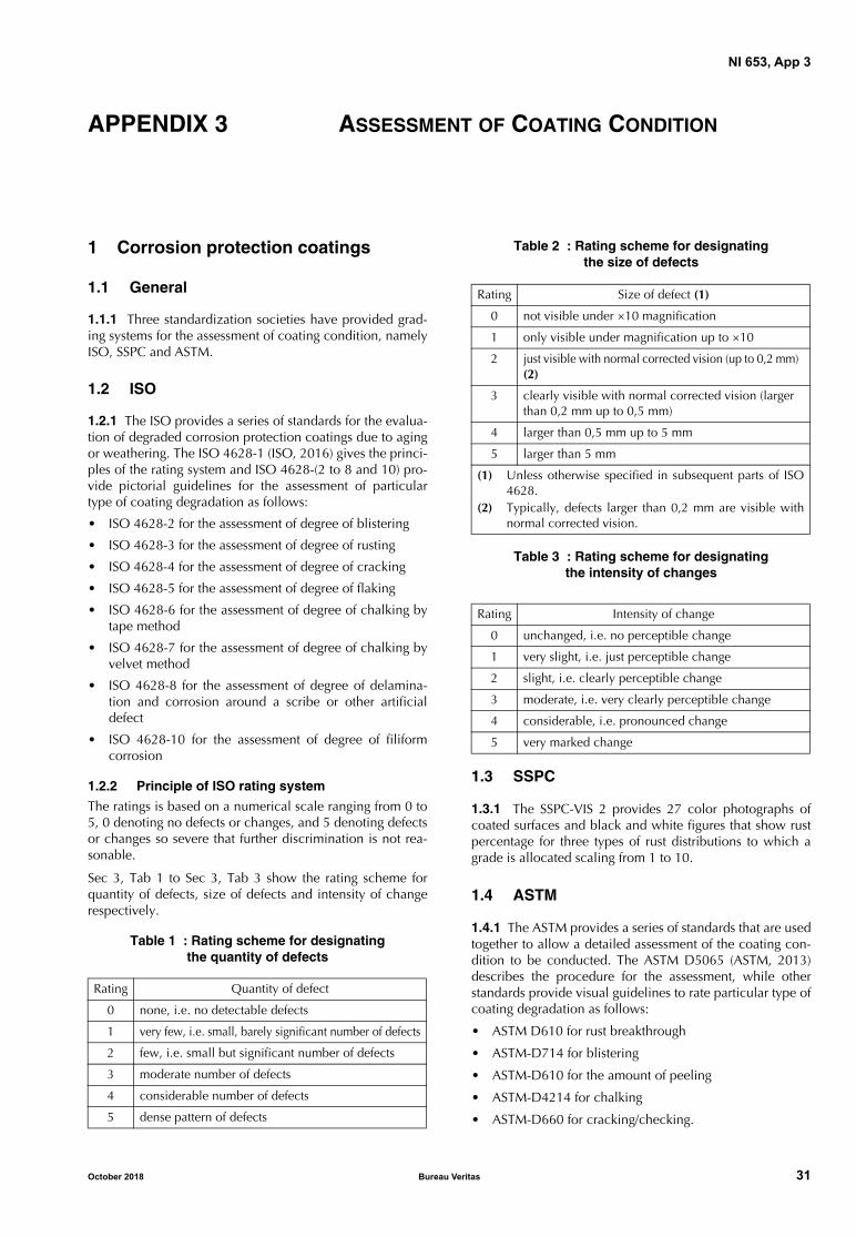
NI 653, App 3
APPENDIX 3 ASSESSMENT OF COATING CONDITION
1 Corrosion protection coatings
1.1 General
1.1.1 Three standardization societies have provided grad-ing systems for the assessment of coating condition, namelyISO, SSPC and ASTM.
1.2 ISO
1.2.1 The ISO provides a series of standards for the evalua-tion of degraded corrosion protection coatings due to agingor weathering. The ISO 4628-1 (ISO, 2016) gives the princi-ples of the rating system and ISO 4628-(2 to 8 and 10) pro-vide pictorial guidelines for the assessment of particulartype of coating degradation as follows:
• ISO 4628-2 for the assessment of degree of blistering
• ISO 4628-3 for the assessment of degree of rusting
• ISO 4628-4 for the assessment of degree of cracking
• ISO 4628-5 for the assessment of degree of flaking
• ISO 4628-6 for the assessment of degree of chalking bytape method
• ISO 4628-7 for the assessment of degree of chalking byvelvet method
• ISO 4628-8 for the assessment of degree of delamina-tion and corrosion around a scribe or other artificialdefect
• ISO 4628-10 for the assessment of degree of filiformcorrosion
1.2.2 Principle of ISO rating system
The ratings is based on a numerical scale ranging from 0 to5, 0 denoting no defects or changes, and 5 denoting defectsor changes so severe that further discrimination is not rea-sonable.
Sec 3, Tab 1 to Sec 3, Tab 3 show the rating scheme forquantity of defects, size of defects and intensity of changerespectively.
Table 1 : Rating scheme for designating the quantity of defects
Table 2 : Rating scheme for designating the size of defects
Table 3 : Rating scheme for designating the intensity of changes
1.3 SSPC
1.3.1 The SSPC-VIS 2 provides 27 color photographs ofcoated surfaces and black and white figures that show rustpercentage for three types of rust distributions to which agrade is allocated scaling from 1 to 10.
1.4 ASTM
1.4.1 The ASTM provides a series of standards that are usedtogether to allow a detailed assessment of the coating con-dition to be conducted. The ASTM D5065 (ASTM, 2013)describes the procedure for the assessment, while otherstandards provide visual guidelines to rate particular type ofcoating degradation as follows:
• ASTM D610 for rust breakthrough
• ASTM-D714 for blistering
• ASTM-D610 for the amount of peeling
• ASTM-D4214 for chalking
• ASTM-D660 for cracking/checking.
Rating Quantity of defect
0 none, i.e. no detectable defects
1 very few, i.e. small, barely significant number of defects
2 few, i.e. small but significant number of defects
3 moderate number of defects
4 considerable number of defects
5 dense pattern of defects
Rating Size of defect (1)
0 not visible under ×10 magnification
1 only visible under magnification up to ×10
2 just visible with normal corrected vision (up to 0,2 mm) (2)
3 clearly visible with normal corrected vision (larger than 0,2 mm up to 0,5 mm)
4 larger than 0,5 mm up to 5 mm
5 larger than 5 mm
(1) Unless otherwise specified in subsequent parts of ISO4628.
(2) Typically, defects larger than 0,2 mm are visible withnormal corrected vision.
Rating Intensity of change
0 unchanged, i.e. no perceptible change
1 very slight, i.e. just perceptible change
2 slight, i.e. clearly perceptible change
3 moderate, i.e. very clearly perceptible change
4 considerable, i.e. pronounced change
5 very marked change
October 2018 Bureau Veritas 31

NI 653, App 3
2 Passive fire protection
2.1 HSE qualitative categorization
2.1.1 HSE categorizes qualitatively the severity of PFP dam-aged condition as follows (HSE, 2007):
a) Severity Level 1 - will cause gross failure of PFP, whensubjected to a fire threat, leading to a significant ele-ment of the protected component becoming exposed tothe fire. Remedial action will involve removal and rein-statement of significant amounts of material and shouldbe undertaken immediately.This level of damage includes:- Unretained and disbonded material- Corrosion or mill scale under an epoxy intumescent- Reinforcement exposed and visibly damaged- Substrate exposed with reinforcement damaged- Major failure of retention system at corners- Water at PFP/substrate interface- Waterlogged or “popped” material- Modification with PFP not reinstated- Addition of attachment with no PFP protection
(absence of PFP protection at some location).
b) Severity Level 2 - provides some protection of substratebut may reduce the fire resistance performance duringthe fire threat to a level that is unacceptable, or is pres-ent in an area of high structural importance, or presentsa falling object or integrity hazard, or will lead to signif-icant deterioration of the material. Remedial action willinvolve a repair requiring reasonable levels of reinstate-ment within an agreed timescale.This includes,- Retained but disbonded material- PFP eroded with retention mesh exposed but intact
- Surface cracks, chips, gouges, scrapes, spalling andtopcoat loss with reinforcement unexposed, butfound in extreme environmental locations or areasof excessive physical exposure where accelerated(area of higher likelihood of damage occurrence)damage can occur (damage occurrence is possible)
- Any surface cracks, chips, gouges, scrapes and spall-ing with reinforcement unexposed but located onedge features of beams and columns.
- Evidence of inadequate material thickness or poorreinforcement at edge features of load bearing struc-tural elements
- Any anomaly that is not a Level 1 anomaly but islocated at a critical structural integrity location
- Evidence of chalking through exposure to UV (Intu-mescent)
- Evidence of heat damage from welded modificationsor operations (Intumescent)
- Part thickness anomalies at edge features of loadbearing structural sections (Intumescent)
- Evidence of inadequate material thickness or poorreinforcement at edge features of load bearing struc-tural elements (Intumescent).
c) Severity Level 3 - minor damage will worsen if notrepaired but does not immediately reduce the fire resis-tance performance. It will lead to deterioration of thematerial leading to 1 or 2 unless corrected. Remedialaction will be minor and will be a maintenance task.This includes:- Surface cracks, chips, gouges, scrapes spalling and
topcoat loss with reinforcement unexposed andlocated in protected environmental locations
- Surface cracks, chips, gouges, scrapes and spallingwith reinforcement unexposed but located in areasof extreme physical exposure.
32 Bureau Veritas October 2018

Marine & Offshore 92937 Paris La Defense Cedex - France
Tel: + 33 (0)1 55 24 70 00 Website: http//www.veristar.com
Email: [email protected] © 2018 Bureau Veritas – All rights reserved


