Risk level in the Norwegian petroleum activities Requirements for the companies' reporting on barrier performance 2008 Rev. 12, 18.11.2010 Contents 0. SUMMARY....................................................................................................................................... 1 1. BACKGROUND AND PURPOSE ................................................................................................. 2 1.1 Earlier stages of the project ............................................................................................................................ 2 1.2 Purpose of the project..................................................................................................................................... 2 1.3 Purpose of the document ................................................................................................................................ 2 2. REPORTING ON BARRIERS - BACKGROUND....................................................................... 2 2.1 Regulations..................................................................................................................................................... 2 2.2 Definitions...................................................................................................................................................... 3 2.3 Overall principles for prioritization of barriers .............................................................................................. 5 2.4 Prioritized barriers.......................................................................................................................................... 5 3. REPORTING OF BARRIERS........................................................................................................ 7 4. REQUIREMENTS FOR BARRIER DATA REPORTING ......................................................... 8 4.1 What is the purpose of the barriers? ............................................................................................................... 8 4.2 Scope of the reporting .................................................................................................................................... 8 4.3 Reporting from the companies ....................................................................................................................... 9 4.4 System limits and failure definitions .............................................................................................................. 9 4.5 Summary of data ............................................................................................................................................ 9 4.6 The PSA's use of the companies' data .......................................................................................................... 11 5. REFERENCE ................................................................................................................................. 11 6. APPENDICES: SYSTEM LIMITS AND ERROR DEFINITIONS .......................................... 12 6.1 Fire detection................................................................................................................................................ 12 6.2 Gas detection ................................................................................................................................................ 13 6.3 Shut-down .................................................................................................................................................... 14 6.4 Well isolation ............................................................................................................................................... 16 6.5 Well isolation with BOP .............................................................................................................................. 17 6.6 Fire protection .............................................................................................................................................. 18 6.7 Emergency Preparedness ............................................................................................................................. 19 6.8 Watertight compartmentalization, hull ......................................................................................................... 21 6.9 Ballast system .............................................................................................................................................. 21 6.10 Stability ........................................................................................................................................................ 21 6.11 HIPPS........................................................................................................................................................... 21
Transcript
Risk level in the Norwegian petroleum activities
Requirements for the companies' reporting on barrier performance
1. BACKGROUND AND PURPOSE ................................................................................................. 2 1.1 Earlier stages of the project ............................................................................................................................ 2 1.2 Purpose of the project..................................................................................................................................... 2 1.3 Purpose of the document ................................................................................................................................ 2
2. REPORTING ON BARRIERS - BACKGROUND....................................................................... 2 2.1 Regulations..................................................................................................................................................... 2 2.2 Definitions...................................................................................................................................................... 3 2.3 Overall principles for prioritization of barriers .............................................................................................. 5 2.4 Prioritized barriers.......................................................................................................................................... 5
3. REPORTING OF BARRIERS........................................................................................................ 7
4. REQUIREMENTS FOR BARRIER DATA REPORTING......................................................... 8 4.1 What is the purpose of the barriers?............................................................................................................... 8 4.2 Scope of the reporting .................................................................................................................................... 8 4.3 Reporting from the companies ....................................................................................................................... 9 4.4 System limits and failure definitions.............................................................................................................. 9 4.5 Summary of data ............................................................................................................................................ 9 4.6 The PSA's use of the companies' data .......................................................................................................... 11
6. APPENDICES: SYSTEM LIMITS AND ERROR DEFINITIONS.......................................... 12 6.1 Fire detection................................................................................................................................................ 12 6.2 Gas detection................................................................................................................................................ 13 6.3 Shut-down .................................................................................................................................................... 14 6.4 Well isolation ............................................................................................................................................... 16 6.5 Well isolation with BOP .............................................................................................................................. 17 6.6 Fire protection .............................................................................................................................................. 18 6.7 Emergency Preparedness ............................................................................................................................. 19 6.8 Watertight compartmentalization, hull......................................................................................................... 21 6.9 Ballast system .............................................................................................................................................. 21 6.10 Stability ........................................................................................................................................................ 21 6.11 HIPPS........................................................................................................................................................... 21
Risk level in the Norwegian petroleum activities Reporting requirements for barriers – 2008 1
j:\prosjekt\p19932 ptil risikonivaa ind\tekst\reporting on barrier performance, rev 12b.doc 22.11.10 Translation from Norwegian
0. Summary The basis is that evaluation and reporting regarding barriers in the project shall not entail a lot of extra
work for the companies. Data from tests (drills in one case) shall be reported for the following selected barriers: Fire detection, availability Gas detection, availability Shutdown, availability
Riser ESDV Closing test Leak test
Wing and master valves, Xmas tree Closing test Leak test
Mooring system Number of situations with one brake not functioning Number of situations when the other brake also fails
A selection of these barriers is used for land facilities.
Risk level in the Norwegian petroleum activities Reporting requirements for barriers – 2008 2
j:\prosjekt\p19932 ptil risikonivaa ind\tekst\reporting on barrier performance, rev 12b.doc 22.11.10 Translation from Norwegian
1. Background and purpose
1.1 Earlier stages of the project One of the focus areas from Phase 2 is empirical data for barriers. The scope has been undergoing development, and has been expanded somewhat over time. Most of the players on the Norwegian Shelf have established systems for following up the performance of barriers, as required by the new HSE management regulations. The requirements for reporting empirical data for barriers is based on this work. Some of these systems are quite extensive as regards internal reporting of empirical data. The companies have both detailed and general indicators. The project has established its own indicators for barriers, based on the same raw data.
1.2 Purpose of the project The purpose of the project has been nearly unchanged during the project's lifetime: The Petroleum Safety Authority Norway shall, in light of the established safety level in the petroleum
activities, carry out an evaluation of status and trends (PSA, 2006). Further development of the major accident risk model to more fully reflect barrier performance has been a consistent objective. Another intention is to make the reporting "broader". The description in the document has been developed for facilities on the Shelf. For land facilities, at least in the initial phase of data collection, only a selection of these barriers will be used.
1.3 Purpose of the document The document describes requirements for reporting experience gained with barriers for Phase 8 of the project, including reflecting the changes and expansions that have been made in previous stages as regards reporting of barrier data. For reporting of reliability data, system boundaries and failure criteria are also presented (in Appendix 1). Exchange of experience with the OREDA project (an international cooperation project where nine oil companies participate, including most of the operators on the Norwegian Shelf) is also relevant. Guidelines for collecting and establishing reliability data for equipment are given in ISO 14224 and NORSOK Z-016, and the OREDA participants have experience with such acquisition of reliability data.
2. Reporting on barriers - background
2.1 Regulations Barriers are a key concept in the new regulations, and reference is also made to them in OLF's guidelines (070) for implementing IEC 61508 and 61511, as well as in ISO standards 13702 and 17776. The following is stated in the Management Regulations (Section 1, risk reduction, second subsection):
Risk level in the Norwegian petroleum activities Reporting requirements for barriers – 2008 3
j:\prosjekt\p19932 ptil risikonivaa ind\tekst\reporting on barrier performance, rev 12b.doc 22.11.10 Translation from Norwegian
”….. In addition, barriers shall be established to a) reduce the probability that any such failures and hazard and accident situations will develop
further, b) limit possible harm and nuisance." The following references to the Management Regulations can be used related to the requirements for mapping of barriers: ”It shall be known what barriers have been established and which function they are intended to fulfil,
cf. Section 1 on risk reduction, second paragraph, and what performance requirements have been defined in respect of the technical, operational or organizational elements which are necessary for the individual barrier to be effective.” (Second section, second subsection)
”It shall be known which barriers are not functioning or have been impaired.” (Second section, third subsection)
The party responsible shall take necessary actions to correct or compensate for missing or impaired barriers.” (Seventh section, second subsection)
These requirements have been used as a basis. The project does not stipulate any requirements beyond those stipulated by the regulations. However, one cannot conclude that one automatically meets the regulatory requirements if the requirements for reporting of barriers in this project are met.
2.2 Definitions
2.2.1 Barrier
The term "barrier" is not defined in the strict sense used in the regulations. The term is used in a broader sense with somewhat differing meanings: Barrier is used synonymously with safety or emergency preparedness system or function In some cases, the barrier term refers to a larger function. It has also been specified that barriers include organizational and administrative measures, not just technical measures as described in the examples here. ISO 17776 has a definition of barriers, which can be expressed as follows when translated from English:
Barrier – measure which reduces the probability of triggering a hazard's potential to cause damage or reduces the damage potential.
It emerges that this definition correlates with the description of barriers in Section 1 of the Management Regulations, see previous sub-chapter.
2.2.2 Safety function, safety system
In Section 1 of the Facilities Regulations, safety system and safety function have been defined as follows:
Risk level in the Norwegian petroleum activities Reporting requirements for barriers – 2008 4
j:\prosjekt\p19932 ptil risikonivaa ind\tekst\reporting on barrier performance, rev 12b.doc 22.11.10 Translation from Norwegian
Safety system: A system which realises one or more active safety functions.
Safety functions: Physical measures which reduce the probability of a situation of hazard and accident occurring, or which limit the consequences of an accident.
The definition of safety function is practically identical with the definition of barrier (see 2.2.1sub-chapter with the limitation that the safety function consists of physical measures, whereas barriers include technical, organizational and administrative measures. The guidelines to the Facilities Regulations give the following examples of safety functions: a) sectioning of the process, b) fire detection, c) gas detection, d) isolation of sources of ignition, e) maintaining overpressure in unclassified spaces, f) starting and stopping fire pumps, both manually
and automatically, g) active fire-fighting h) active smoke control, i) process safety,
j) well safety, k) depressurization, l) general alarm and evacuation alarm, m) production and distribution of
emergency power, n) emergency lighting, o) emergency drainage, P) ballasting for mobile facilities, Q) maintenance of correct pressure,
humidity, temperature and gas composition in diving facilities.
2.2.3 The project's definition of barrier
The project uses the definition in ISO 17776 as its basis. This means that barrier can usually be used synonymously with safety or emergency response function including associated logic, or corresponding operational and organizational measures to reduce probability and/or consequences. Barrier can in many cases be described as follows: Facility or measure which influences the progress of an accident in the intended direction, - reducing
losses (or expected losses). Barriers will often correspond to branching points in the incident trees in a QRA, and this applies to a great degree to the list in this sub-chapter. The term barrier is, according to the definition used, somewhat broadly defined. In some contexts, it may be relevant to consider "parts of a barrier”, and the term "barrier elements" is used in this context. The transition between barrier and barrier element is somewhat flexible.
2.2.4 Barrier performance
The guidelines to the Management Regulations explain the term performance as follows: ”Performance as mentioned in the second subsection can include capacity, reliability, accessibility,
efficiency, ability to resist loads, integrity and robustness.” (Second section, Guidelines)
Risk level in the Norwegian petroleum activities Reporting requirements for barriers – 2008 5
j:\prosjekt\p19932 ptil risikonivaa ind\tekst\reporting on barrier performance, rev 12b.doc 22.11.10 Translation from Norwegian
Performance can be considered to have the following three components, which can be described as follows: Functionality/efficiency: The effect the barrier has on the progress of the accident, given that it is
present (functions) as assumed in the design.
Availability/reliability: The barrier's ability to be available on demand
The robustness (inverted vulnerability): the barriers' ability to function during relevant (specified) courses of events in accidents in connection with accidental loads.
2.3 Overall principles for prioritization of barriers The following principles have been employed in the selection of barriers for reporting: Focus in the selection of barriers is set on the DFUs which the project has shown to have the largest
risk contributions.
Barriers which can stop a chain of events from developing at an early stage should be given priority. In addition, the following aspects have been emphasised:
The overall reporting of barriers must be such that they instil confidence from all parties.
The barrier indicators should cover the broadest possible range, from barriers which prevent incidents from developing into accidents, to emergency preparedness systems and measures.
Reporting of barriers is based on the requirements in the new regulations, and should as far as possible be given the same interpretation as in the regulations, including organizational and administrative measures.
Experience from establishment of indicators suggests that this should start with technical barriers, as it is considerably more challenging to establish indicators for organizational and administrative barriers.
The barrier reporting requirements are based on these principles.
2.4 Prioritized barriers On the basis of the overall principles in sub-chapter 2.3, the following DFUs can be identified as having the highest risk contribution: DFU1-2: Hydrocarbon leaks DFU3: Well kicks/loss of well control DFU5: Ships on collision course DFU8: Construction and marine incidents DFU12: Helicopter accident at/on facility/field In the further identification of barriers, the primary emphasis is on the barriers which affect the development of these DFUs. Based upon the overall principles in sub-chapter 2.3, the following technical barriers/barrier elements can be identified as having the highest priority:
Risk level in the Norwegian petroleum activities Reporting requirements for barriers – 2008 6
j:\prosjekt\p19932 ptil risikonivaa ind\tekst\reporting on barrier performance, rev 12b.doc 22.11.10 Translation from Norwegian
DFU1-2
Integrity of process facilities Gas detection Ignition source control Emergency shut-down Process control Depressurization Fire detection Mustering and evacuation
DFU3
Well kicks/loss of well control detection BOP w/pressure control equipment Valves for well shutdown Mustering and evacuation
DFU5
Detection of ships on collision course Measures to alert ship to change course Mustering and evacuation
DFU8
Components in the ballast system Components in the mooring system Active elements in watertight compartmentalization Mustering and evacuation
DFU12
(Is currently being discussed with the authorities and helicopter operators) The following barriers have, on the basis of assessments of the focus among the parties in the industry, been identified as having a correspondingly high priority: Firewater supply Deluge systems Means of evacuation MOB boat The barriers which have been selected for pilot projects are shown in sub-chapter 4.2.1. An overview of the barriers which have not been selected and the arguments for their deselection are shown below.
2.4.1 Comments to the barriers which have not been selected in the project
There are some barriers which are usually considered to be crucial but which have not been included in the pilot project, for various reasons. This is discussed briefly below.
Risk level in the Norwegian petroleum activities Reporting requirements for barriers – 2008 7
j:\prosjekt\p19932 ptil risikonivaa ind\tekst\reporting on barrier performance, rev 12b.doc 22.11.10 Translation from Norwegian
Loss of integrity in process facilities
Covered by reporting of DFU1.
Ignition prevention Often referred to as the most important barrier in the process area, second only to preventing leaks. Shutdown of electrical ignition sources and limitation of hot work are relevant measures to reduce the risk of ignition. However, there are presently few companies which record data related to this barrier. A decision has therefore been made not to include this barrier in the pilot project. This barrier is highly relevant for future expansions.
Blowdown/depressurization Process safety Ventilation Drain system Foam facility
Few companies presently record data related to these barriers.
As there are already several barriers related to the process area, a decision has been made to not include these barriers in the pilot project.
Fire and explosion barriers Few companies presently record data related to these barriers. As they are passive, it is not easy to identify representative data for collection.
Sea monitoring (collision risk)
Measures to alert ship to need for changing course
Covered by the reporting of DFU5.
Emergency power and lighting
Alarm and warning systems Mobilization of response
teams
Few companies presently record data related to these barriers. As limiting the number of barriers which are to be reported is a key issue, a decision has been made to not include these barriers in the pilot project.
3. Reporting of barriers The following key premises have been used as a basis for the requirements for reporting and assessment of barrier performance in the project: Data collection and analysis should, insofar as possible, take place in the industry.
The basis for making assessments is best in the companies, and this should primarily take place in the companies. Both these items reflect the fact that it is the companies which to a considerable degree will have the best insight, and will in this respect be able to make relevant and nuanced assessments.
The companies have a duty to establish indicators in accordance with Section 7 of the Management Regulations (see sub-chapter 2.1). It is therefore natural to, insofar as possible, base the fulfilment of relevant requirements in the new regulations on the companies' own activities. It will therefore be an objective to limit the submitted volume to that which is necessary for the purpose. The plan is to facilitate a limited submission of data.
The assessments and data collection are limited to the production facilities, with the exception of well isolation with BOP, maintenance management and marine systems.
Risk level in the Norwegian petroleum activities Reporting requirements for barriers – 2008 8
j:\prosjekt\p19932 ptil risikonivaa ind\tekst\reporting on barrier performance, rev 12b.doc 22.11.10 Translation from Norwegian
4. Requirements for barrier data reporting
4.1 What is the purpose of the barriers? All companies test the barriers on the facilities. There has been come variation as regards the systematization of the test data, and thus the basis for indicating reliability and accessibility. In this part of the project relating to barriers, the purpose is to achieve reporting of reliability and availability data from the companies to achieve a limited number of barriers. It is necessary to record data for some selected barriers to achieve participation from all parties.
4.2 Scope of the reporting
4.2.1 Selected barriers
The selected barriers which data will be reported for are as follows: Fire detection, accessibility Gas detection, accessibility Shut-down, accessibility
Isolation with BOP, accessibility Drilling and well activities Subsea and surface BOP including drilling, wireline, snubbing and coiled tubing BOP
Active fire protection Deluge valves Firewater supply, start failure
HIPPS HIPPS/QSV valve including signalling device, pilot/solenoid and logic (only for land-based facilities)
Emergency Preparedness Muster time, actual value Ratios between actual value and SEPRA
Test data for subsea BOP and surface BOP are associated with drilling and well activities. Data for all barriers, with the exception of emergency preparedness, should be based on test data, from planned and/or not planned tests. Muster time based on emergency preparedness exercises. All these barriers are considered key barriers at the facilities. The first three are related to the process and well area, which are important areas in relation to the consideration of experienced risk. The authority regulations place considerable emphasis on these areas. For these barriers, the relevant barriers are based on the definitions in Appendix A of OLF guideline 070, for compliance with IEC 61508 and 61511.
Risk level in the Norwegian petroleum activities Reporting requirements for barriers – 2008 9
j:\prosjekt\p19932 ptil risikonivaa ind\tekst\reporting on barrier performance, rev 12b.doc 22.11.10 Translation from Norwegian
As regards fire and gas detection, it is not necessary to separate between different types of detectors. For shutdown valves, the reporting has been limited to the most critical, those isolating against the reservoir and the pipelines. Active fire protection is a key barrier for both ignited hydrocarbon leaks and other fires. Here, there are also strict limitations concerning what is to be reported, test data for deluge valves and start-up failure for fire pumps. Mustering at the lifeboat station/in safe area is a barrier which works for all major accident near misses. There is in that regard a certain range in the types of included barriers, although the emphasis is on the process and well area. This corresponds with the authorities' regulations, the companies' own focus and assessments related to experienced risk. Practically all the barriers are of the type which is presently tested on the facilities, the challenges will be related to data capture and systematization, for the companies to a varying degree. Safety-related equipment (e.g. fire detectors, gas detectors, valves, firewater pumps) is included in the OREDA project. Before an implementation phase, it should be considered whether cooperate with this project, to assess the options provided by OREDA-24 Databank.
4.2.2 Barriers – marine systems
The following barrier data are reported for marine systems:
Closing of watertight doors Valves in the ballast system Mooring system
o Number of situations with one brake not functioningo Number of situations where the other brake also fails
4.2.3 Maintenance management
Decision basis for maintenance management Status for completed maintenance work
4.3 Reporting from the companies The companies report barrier data twice a year
4.4 System limits and failure definitions Appendix 1 shows examples of system limits and failure definitions for the barriers which are included in the pilot project for barriers. It is emphasized that when valves are tested, it is the first closure attempt that is to be reported.
4.5 Summary of data For the reporting of data, emphasis is placed on only receiving summary data, without underlying data, as shown in Table 1.
Risk level in the Norwegian petroleum activities Reporting requirements for barriers – 2008 10
j:\prosjekt\p19932 ptil risikonivaa ind\tekst\reporting on barrier performance, rev 12b.doc 22.11.10 Translation from Norwegian
Table 1 Barrier data for submission
Reported data Barrier Number of tests Number of failures
according to definition Fire detection, accessibility Number of tests of detectors/logic
throughout the year Number of failures
Gas detection, accessibility Number of tests of detectors/logic throughout the year
Number of errors
Number of tests of riser ESDV throughout the year Separated into number
closing tests and leak tests
Number of errors Separated into number of
tests for closing test and leak test
Number of tests of pressure relief valve, BDV
Number of errors
Number of tests of safety valve, PSV
Number of errors
Number of tests of wing and master valves (Xmas tree) throughout the year Separated into number of
tests for closing test and leak test
Number of errors Separated into number of
tests for closing test and leak test
Shut-down, accessibility
Number of tests of DHSV throughout the year
Number of errors
Isolation with BOP Separate test and failure data for subsea and surface BOP: BOP for drilling activities BOP for coiled tubing
activities BOP for cable activities BOP for snubbing activities
Number of tests per seal element in BOP throughout the year
Number of errors per seal element in BOP
Number of tests of deluge valves throughout the year
Number of errors Active fire protection
Number of start tests with fire pumps throughout the year
Number of errors
Muster times observed throughout the year for muster drills
Ratios between actual muster time and associated SEPRA
Emergency preparedness
The number of persons who participated in the individual mustering drills
Watertight compartmentalization Number of tests with closing of watertight doors
Number of errors
Ballast system Number of tests of valves in the ballast system
Number of errors
Mooring system Number of situations with one brake not functioning Number of situations where the other brake also fails
Number of errors
The definition of system limits for each of the barriers is shown in chapter 6.
Risk level in the Norwegian petroleum activities Reporting requirements for barriers – 2008 11
j:\prosjekt\p19932 ptil risikonivaa ind\tekst\reporting on barrier performance, rev 12b.doc 22.11.10 Translation from Norwegian
4.6 The PSA's use of the companies' data For each individual reported barrier, the PSA will estimate average values for accessibility and reliability for all companies. Over time, such calculations can show trends.
5. Reference NPD, 2001. Development in risk levels - the Norwegian Shelf, Pilot project report 2000, Summary, the Norwegian Petroleum Directorate (http://www.npd.no) 19 April 2001 OLF, 2001. Recommended guidelines for the application of IEC 61508 and IEC 61511 in the petroleum activities on the Norwegian Continental Shelf, OLF guideline 070, February 2001 ISO, 1998. Petroleum and natural gas industries — Offshore production installations-Control and mitigation of fires and explosions — Requirements and guidelines, ISO 13702 ISO, 2000. Petroleum and natural gas industry — Offshore production installations — Guidelines on tools and techniques for identification and assessment of hazards, ISO 17776 NORSOK standard D-010 “Well integrity in drilling and well operations”, Rev. 3, August 2004: NORSOK Z-016 "Regularity management & Reliability Technology", Rev.1, December 1998 ISO 14224 "Collection and exchange of reliability and maintenance data for equipment", July 1999 OREDA industry project (www.oreda.com)
Risk level in the Norwegian petroleum activities Reporting requirements for barriers – 2008 12
j:\prosjekt\p19932 ptil risikonivaa ind\tekst\reporting on barrier performance, rev 12b.doc 22.11.10 Translation from Norwegian
6. Appendices: System limits and error definitions This chapter describes system limits and failure definition for the barriers which are included in the description of data collection in Chapter 4. The definitions and limits follow OLF guideline 070 where relevant.
6.1 Fire detection
6.1.1 System limits
Figure 1 shows system limits for data collection for the fire detection barrier.
Figure 1 System limits for fire detection
6.1.2 Test procedure
All detectors are tested up to and including entry to fire function of F&G logic. Restricted to automatic detection.
6.1.3 Failure definition
The following definition has been established for the definition of failures according to the system limits in Figure 1: F&G logic does not receive signals from detectors The indicator is counted per detector ’ Signal’ here refers to a signal which will activate an alarm in F&G panels.
Deteksjon- Flamme- Røyk- Varme
F&G logikk
Systemgrense
Risk level in the Norwegian petroleum activities Reporting requirements for barriers – 2008 13
j:\prosjekt\p19932 ptil risikonivaa ind\tekst\reporting on barrier performance, rev 12b.doc 22.11.10 Translation from Norwegian
6.2 Gas detection
6.2.1 System limits
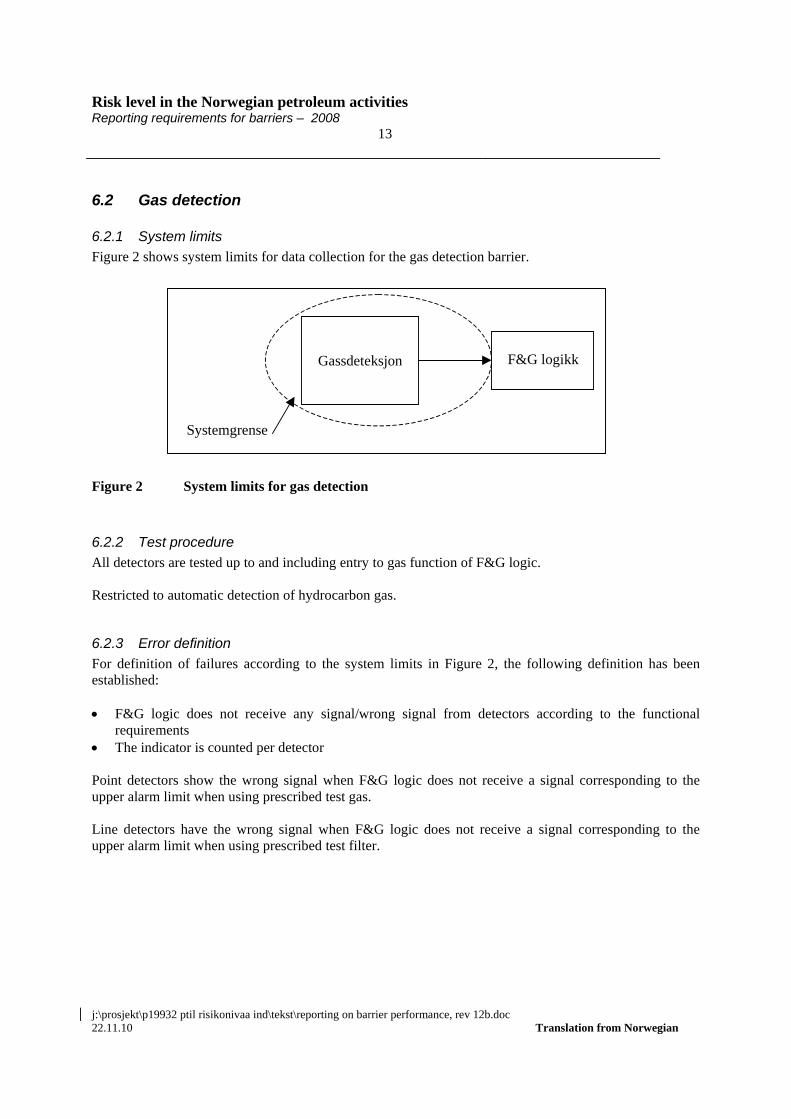
Figure 2 shows system limits for data collection for the gas detection barrier.
Figure 2 System limits for gas detection
6.2.2 Test procedure
All detectors are tested up to and including entry to gas function of F&G logic. Restricted to automatic detection of hydrocarbon gas.
6.2.3 Error definition
For definition of failures according to the system limits in Figure 2, the following definition has been established: F&G logic does not receive any signal/wrong signal from detectors according to the functional
requirements The indicator is counted per detector Point detectors show the wrong signal when F&G logic does not receive a signal corresponding to the upper alarm limit when using prescribed test gas. Line detectors have the wrong signal when F&G logic does not receive a signal corresponding to the upper alarm limit when using prescribed test filter.
Gassdeteksjon F&G logikk
Systemgrense
Risk level in the Norwegian petroleum activities Reporting requirements for barriers – 2008 14
j:\prosjekt\p19932 ptil risikonivaa ind\tekst\reporting on barrier performance, rev 12b.doc 22.11.10 Translation from Norwegian
6.3 Shut-down The shutdown function includes riser ESD valves, pressure relief valve, BDV, and safety valve, PSV.
6.3.1 System limits – ESD valves
Figure 3 shows system limits for data collection for the shutdown barrier.
Figure 3 System limits for shut down with ESV
6.3.2 Test procedure - ESV
ESVs are tested from signal from ESD logic up to and including function of valve, including solenoid valve. Restricted to ESVs against pipelines/risers (and against hydrocarbon reservoirs, see sub-chapter 6.4).
6.3.3 Failure definition - ESV
The following definition has been established for the definition of errors according to the system limits in Figure 3: ESV does not close within the safety critical timespan, or ESV has a higher internal leak rate than the specified value (safety critical rate for the relevant valve) The indicator is counted per ESV, including signal exchange from ESD logic and solenoid valve The two failure modes closing failure and internal leak are reported separately. Safety critical closing time is:
Valve not closing within specified closing time when this has been established in connection with risk assessments.
2 seconds per inch (for example 12” valve = 24 seconds) where closing time is not specified.
6.3.4 System limits – pressure relief valves
Figure 4 shows system limits for data collection for the depressurization, BDV, barrier.
ESD logikk Solenoid ESV
Systemgrense
Risk level in the Norwegian petroleum activities Reporting requirements for barriers – 2008 15
j:\prosjekt\p19932 ptil risikonivaa ind\tekst\reporting on barrier performance, rev 12b.doc 22.11.10 Translation from Norwegian
Logikk Solenoid BDV
Systemgrense
Figure 4 System limits for pressure relief valve
6.3.5 Test procedure – BDV valves
BDVs are tested from signal from logic and up to and including function of valve, including solenoid valve.
6.3.6 Failure definition – BDV valves
The following definition has been established for the definition of errors according to the system limits in Figure 3: BDV does not open within the specified time The indicator is counted per BDV, including signal exchange from logic and solenoid valve
6.3.7 System limits – PSV valves
Figure 5 shows system limits for data collection for the depressurization barrier.
Figure 5 System limits for safety valve
6.3.8 Test procedure – PSV valves
PSVs are tested during pressurization (x% above set value) of valve, including holding mechanism.
Holdemeka-nisme
PSV
Systemgrense
Risk level in the Norwegian petroleum activities Reporting requirements for barriers – 2008 16
j:\prosjekt\p19932 ptil risikonivaa ind\tekst\reporting on barrier performance, rev 12b.doc 22.11.10 Translation from Norwegian
6.3.9 Failure definition – PSV valves
For definition of errors according to the system limits in Figure 3, the following definition has been established: PSV does not open at the 120% of set point or over 50 bar, whichever is lower. The indicator is counted per PSV
6.4 Well isolation
6.4.1 System limits
Figure 6 shows an example of system limits for data collection for the isolation of production well barrier.
Figure 6 Example of system limits for well isolation, production well
”DHSV” in Figure 6 should be interpreted to include downhole safety valve (DHSV).
6.4.2 Test procedure
Wing, master and DHSV are tested from signal from ESD logic and up to and including valve function, including ESD solenoid valve. Each valve is tested separately. All production wells, at the facility and subsea production well.
6.4.3 Error definition
For definition of errors according to the system limits in Figure 6, the following definition has been established:
ESD logikk Solenoid,ESD
Masterventil
DHSV
Vingventil
Systemgrense
Risk level in the Norwegian petroleum activities Reporting requirements for barriers – 2008 17
j:\prosjekt\p19932 ptil risikonivaa ind\tekst\reporting on barrier performance, rev 12b.doc 22.11.10 Translation from Norwegian
The valve does not close according to function within the specified time (time requirement does not
apply to DHSV and similar) The valve has a higher internal leak rate (i.e. pressure build-up) than the specified value (in own
procedure or according to API14B). The indicators is counted per valve (wing, master, DHSV), including solenoid and signal exchange
from ESD logic The two error modes closing error and internal leak are reported separately.
6.5 Well isolation with BOP
6.5.1 System limits
Figure 7 shows an example of system limits for data collection for the isolation of well during drilling with BOP barrier. It is differentiated between BOP for individual purposes.
Aktivering av BOPsom følge av testeller brønnkontroll
situasjon
Borers BOPaktiveringspanel
Boresjefs BOPbackup panel
Manueltpanel/hovedpanel
Elektriskstyresignal
Manuell styring
Akkumulator/hovedenhet
Blind/shearram
Upper piperam
Lower piperam
Annularpreventer
Akustiskaktiveringspanel
Akustisk signal
Systemprense
Figure 7 Example of system limits for well isolation with BOP
6.5.2 Test procedure
The valves in BOP are leak tested separately, by observing the pressure drop above the valve. Reference is made to NORSOK D-010 Section 15. Well barrier elements acceptance tables, D. Initial test and verifications. Use of BOP at the facility and subsea is included.
Risk level in the Norwegian petroleum activities Reporting requirements for barriers – 2008 18
j:\prosjekt\p19932 ptil risikonivaa ind\tekst\reporting on barrier performance, rev 12b.doc 22.11.10 Translation from Norwegian
6.5.3 Error definition
The following definition has been established for the definition of errors according to the system limits in Figure 7: The valve in BOP does not maintain constant pressure over a given period of time Number of failures are counted per seal element with reference to NORSOK D-010 Table A.1 Number of tests is defined as number of pressure test per seal element in BOP. For pressure drop requirements, see NORSOK D010, Ch. 4.2.3.5 Leak testing of well barriers.
6.6 Fire protection
6.6.1 System limits
Figure 8 shows system limits for data collection for the barriers related to the fire protection function.
Figure 8 System limits for fire protection
There are two sets of system limits in Figure 8, for firewater supply (system 1, to ring main) and deluge valves for valves for loops in the process areas (system 2). These have their respective test procedures and failure definitions. This means that there are two indicators which must be recorded for active fire protection.
6.6.2 Test procedure – deluge valves
Deluge panels and deluge valves are tested, including feedback to F&G/ESD. Each valve is tested separately.
Motor 1 Kraftover-føring
Pumpe 1Deluge ventil
F&G logikk
Motor 2 Kraftover-føring
Pumpe 2
Ringled-ning
Deluge ventil
·
·
·
·Eventuelt flere parallelle tog
Deluge ventil
12
Systemgrense
Deluge panel
Risk level in the Norwegian petroleum activities Reporting requirements for barriers – 2008 19
j:\prosjekt\p19932 ptil risikonivaa ind\tekst\reporting on barrier performance, rev 12b.doc 22.11.10 Translation from Norwegian
6.6.3 Failure definition – deluge valves
The following definition has been established for the definition of failures relating to deluge valves according to the system limits in Figure 8: Deluge valve does not open The indicator is counted per deluge control valve, including signal exchange from manual/automatic
activation in the deluge panel
6.6.4 Test procedure – firewater supply
This is an indicator which must be reported:
Start-up failure Fire pumps and start sequence are tested, including continuous monitoring of the pump's status. The indicator is counted per pump, regardless of the capacity of each pump compared with the defined need for firewater.
6.6.5 Failure definition – firewater supply
The following definition has been established for firewater supply according to the system limits in Figure 8: Start-up failure, firewater pump or engine (1 unit) i.e. does not start to pump water at the first attempt
6.7 Emergency Preparedness
6.7.1 System limits
Figure 9 shows system limits for data collection for the mustering barrier.
Risk level in the Norwegian petroleum activities Reporting requirements for barriers – 2008 20
j:\prosjekt\p19932 ptil risikonivaa ind\tekst\reporting on barrier performance, rev 12b.doc 22.11.10 Translation from Norwegian
Figure 9 System limits for mustering
6.7.2 Test procedure
Mustering is carried out as drills according to the emergency instructions. Data can also be recorded during actual muster alarms situations. The system for registration of turnout at the muster points is also included, until everyone on board has been accounted for. The indicator shall record the time elapsed until mustering is complete in relation to the facility's specific muster time requirements.
6.7.3 Definition of response
The following definition has been established for the definition of response according to the system limits in Figure 9: Turnout and reporting at all muster stations according to emergency procedures and any
circumstances defined for the relevant scenario. Mustering shall not be considered completed before the location of all persons is known.
Mønstringi hht
instruks
Registr.(man/aut)i hht liste
ESDlogikk
Alarmover PA
Mønstringi hht
instruks
Registr.(man-/aut)i hht liste
Alle ombord gjortrede for
·
·Eventuelt fleremønstrings-steder
Systemgrense
Risk level in the Norwegian petroleum activities Reporting requirements for barriers – 2008 21
j:\prosjekt\p19932 ptil risikonivaa ind\tekst\reporting on barrier performance, rev 12b.doc 22.11.10 Translation from Norwegian
6.8 Watertight compartmentalization, hull
6.8.1 System limits
The system included consists of watertight doors which are part of the hull for floating facilities. The door itself, the closing mechanism and the signal transfer are included.
6.8.2 Test procedure
The closing mechanism and door are included in the test. Each door is tested separately. The number of doors tested is recorded.
6.8.3 Error definition
Door not closing completely (locking) within the specified time. Doors which are not completely closed during testing or which do not close within the time requirements stipulated by Sections 38 and 41 of the Norwegian Maritime Directorate's Regulations of 20 December 1991 No. 878 relating to stability, watertight compartmentalization and watertight/weatherproof closing mechanism at mobile installations.
6.9 Ballast system
6.9.1 System limits
The system included is limited to valves in the ballast system, including solenoids and signal transfer.
6.9.2 Test procedure
Signal transfer, solenoids and valves are included in the test. Each valve is tested separately. The number of valves tested is recorded.
6.9.3 Error definition
Valve opens/does not close within the specified time when tested.
6.10 Stability GM value (meta centre height) for inact condition to be reported at the end of the year for semis and vessel-like installations.
6.11 HIPPS There are several versions of HIPPS. The most common are: a) Valves / QSV which is activated by a dedicated pressure switch (PSHH) via a pilot or solenoid valve b) Valve/ QSV which is activated by pressure transmitter(s) via logic and pilot or solenoid valve, if relevant. The total HIPPS function can consist of one or more independent loops/valves in sequence and/or in parallel.
Risk level in the Norwegian petroleum activities Reporting requirements for barriers – 2008 22
j:\prosjekt\p19932 ptil risikonivaa ind\tekst\reporting on barrier performance, rev 12b.doc 22.11.10 Translation from Norwegian
6.11.1 System limits – HIPPS
Figure 10 shows the system limit for data collection for the HIPPS barrier.
Figure 10 System limit for HIPPS
6.11.2 Test procedure Each HIPPS valve/HIPPS loop is tested with signal from pressure switch/pressure transmitter including logic, pilot/solenoid up to and including function of valve. Each valve is tested separately.
6.11.3 Failure definition The following definition has been established for definition of failures according to the system limits in Figure 10: The valve does not close according to function within the specified time The indicator is counted per HIPPS/QSV valve including signalling device, pilot/solenoid and logic
6.12 Maintenance management
6.12.1 Decision basis for maintenance management
Number of tagged equipment in total Number of tags that are classified Number of tags classified as HES critical Time of last classification
Pilot Solenoid
HIPPS ventil QSV
PSHH PT Logik
Systemgrense
Risk level in the Norwegian petroleum activities Reporting requirements for barriers – 2008 23
j:\prosjekt\p19932 ptil risikonivaa ind\tekst\reporting on barrier performance, rev 12b.doc 22.11.10 Translation from Norwegian
Definitions and explanations are shown in the Excel spreadsheet.
6.12.2 Status for performed maintenance
Number of hours PM (Preventive Maintenance) Number of hours CM (Corrective Maintenance) Number of hours modifications and project Number of hours revision shut down PM backlog, number of hours in total PM backlog, number of hours HES critical CM backlog, number of hours in total CM backlog, number of hours HES critical Definitions and explanations are shown in the Excel spreadsheet.