sustainability Article Risk Management in Critical Infrastructure—Foundation for Its Sustainable Work Andrzej Bialas Institute of Innovative Technologies EMAG, 40-189 Katowice, Leopolda 31, Poland; [email protected]; Tel.: +48-32-200-77-00; Fax: +48-32-200-77-01 Academic Editors: Adam Jablo ´ nski, Giuseppe Ioppolo and Marc A. Rosen Received: 24 October 2015; Accepted: 26 February 2016; Published: 4 March 2016 Abstract: The paper concerns research related to the European project CIRAS and presents a validation experiment with the use of a risk management tool adapted for critical infrastructures. The project context and state of the art are discussed. The adaptation of the risk management tool is performed according to previously elaborated requirements which consider interdependencies, cause-consequences analysis, risk measures and risk register implementation. A novel structured risk management method was proposed how to deal with internal and external impacts of a hazardous event which occurred in the given CI. The method is embedded into the critical infrastructure resilience process. These requirements can be implemented on the ready-to-use software platform for further experiments. The experimentation results are used as the input for CIRAS. The discussed tool can be applied as the risk reduction component in the CIRAS Tool, and the validation process presented here is the basis to elaborate two project use cases. Keywords: critical infrastructure; risk management; bow-tie concept; software tool; interdependencies 1. Introduction The paper concerns the risk management issue in critical infrastructures. Today’s societies are based on products and services provided by large-scale technical infrastructures of such sectors as energy, oil, gas, finances, transport, telecommunications, health, etc. These infrastructures, when disrupted or destroyed, have a serious impact on health, safety, security or well-being of the society or effective functioning of governments and/or economies, therefore they are called critical infrastructures (CIs). Smooth functioning of the CIs builds right relationships between the citizens and governments. Modern societies are very sensitive to any disturbances in critical infrastructures. The CI disturbances or damages hamper the economic growth, social prosperity and sustainable development of our civilization. For this reason, it is very important to mitigate any negative impact on critical infrastructures. Risk management, which plays the key role in the CI protection, still remains a challenge due to many unresolved problems. This was the author’s motivation to undertake research in this field. CI is identified as a very complex socio-technical system, sometimes called a system of systems. The system of systems (SoS) consists of multiple, heterogeneous, distributed, occasionally independently operating systems embedded in networks at multiple levels, which evolve over time [1]. To function properly, CIs include many diversified components (technological, IT hardware, software, environmental, personal, organizational) and complex processes interrelated with other processes across different economy sectors. In such environments different kinds of threats and hazards may occur, such as: natural disasters and catastrophes, technical disasters and failures, espionage, international crime, physical and cyber terrorism. To avoid disturbances in CIs and to minimize possible consequences of threats, critical infrastructure protection (CIP) programmes are implemented, which specify a consistent set of Sustainability 2016, 8, 240; doi:10.3390/su8030240 www.mdpi.com/journal/sustainability
Transcript
sustainability
Article
Risk Management in CriticalInfrastructure—Foundation for Its Sustainable WorkAndrzej Bialas
Institute of Innovative Technologies EMAG, 40-189 Katowice, Leopolda 31, Poland; [email protected];Tel.: +48-32-200-77-00; Fax: +48-32-200-77-01
Academic Editors: Adam Jabłonski, Giuseppe Ioppolo and Marc A. RosenReceived: 24 October 2015; Accepted: 26 February 2016; Published: 4 March 2016
Abstract: The paper concerns research related to the European project CIRAS and presents avalidation experiment with the use of a risk management tool adapted for critical infrastructures.The project context and state of the art are discussed. The adaptation of the risk management toolis performed according to previously elaborated requirements which consider interdependencies,cause-consequences analysis, risk measures and risk register implementation. A novel structured riskmanagement method was proposed how to deal with internal and external impacts of a hazardousevent which occurred in the given CI. The method is embedded into the critical infrastructureresilience process. These requirements can be implemented on the ready-to-use software platform forfurther experiments. The experimentation results are used as the input for CIRAS. The discussedtool can be applied as the risk reduction component in the CIRAS Tool, and the validation processpresented here is the basis to elaborate two project use cases.
The paper concerns the risk management issue in critical infrastructures. Today’s societies arebased on products and services provided by large-scale technical infrastructures of such sectorsas energy, oil, gas, finances, transport, telecommunications, health, etc. These infrastructures,when disrupted or destroyed, have a serious impact on health, safety, security or well-being ofthe society or effective functioning of governments and/or economies, therefore they are called criticalinfrastructures (CIs). Smooth functioning of the CIs builds right relationships between the citizensand governments. Modern societies are very sensitive to any disturbances in critical infrastructures.The CI disturbances or damages hamper the economic growth, social prosperity and sustainabledevelopment of our civilization. For this reason, it is very important to mitigate any negative impact oncritical infrastructures. Risk management, which plays the key role in the CI protection, still remains achallenge due to many unresolved problems. This was the author’s motivation to undertake researchin this field.
CI is identified as a very complex socio-technical system, sometimes called a system ofsystems. The system of systems (SoS) consists of multiple, heterogeneous, distributed, occasionallyindependently operating systems embedded in networks at multiple levels, which evolve over time [1].To function properly, CIs include many diversified components (technological, IT hardware, software,environmental, personal, organizational) and complex processes interrelated with other processesacross different economy sectors.
In such environments different kinds of threats and hazards may occur, such as: natural disastersand catastrophes, technical disasters and failures, espionage, international crime, physical and cyberterrorism. To avoid disturbances in CIs and to minimize possible consequences of threats, criticalinfrastructure protection (CIP) programmes are implemented, which specify a consistent set of
diversified security measures applied for the given CI: technical, organizational and procedural.The measures should properly affect the identified risk. The measures selection is based on riskmanagement principles.
1.1. Resilience and Risk Management in Critical Infrastructures
Risk management is a continuous process including the identification, analysis, and assessmentof potential hazards in a system or hazards related to a certain activity. Based on the recognized riskpicture, the risk control measures are proposed to eliminate or reduce potential harms to people,environment, or other assets. The risk management process encompasses risk monitoring andcommunication. ISO 31000 [2] is the basic risk management standard. Examples of the most recognizedrisk management methods and techniques are included in IEC 31010 [3].
The risk management issue in critical infrastructures has a specific character because CIs are verycomplex, diversified and there are mutual interrelations between different infrastructures. Becauseof relationships between infrastructures, the state of each infrastructure influences or is correlated tothe state of the other. They are called interdependencies [4–7] and can be divided to four categories:physical, cyber, geographical and logical interdependency. The effects of an incident may propagateacross CIs with dire consequences. The paper takes into account interdependencies, however thecomplex interdependencies issues are not the basic topic of the paper.
Well-secured CIs can resist external and internal disturbances and are able to work on anacceptable efficiency level even when these disturbances occur. To improve the CI resilience is the mainobjective of CI stakeholders. The CIs resilience is an effective, sustainable use of critical infrastructuresby stakeholders to perform tasks for the economy, government and citizens. “The concept of resiliencecan be seen as a superset in which typical risk assessment is a complementary part” [6]. The followingactivities leading to the CI resilience are proposed in this publication:
‚ preparing the CI specification based on the structural analysis—the most critical elements, the mostvulnerable points, dependencies and interdependencies are identified; please note: dependencydefines a unidirectional relationship between infrastructures, while interdependency defines abidirectional relationship;
‚ running the dynamic analysis to identify the most dangerous risk scenarios—generally the subjectof analysis or simulation are: propagation of dire effects of CIs phenomena, identification ofthe threats impact, analyses of common failures, system response to a failure or an incident,recovery process, etc.
‚ the most dangerous risk scenarios, prioritized, are taken into account later during the riskmanagement process.
1.2. Research Related to the CIRAS Project
The critical infrastructure protection is recognized in European Union (EU) as one of the keyissues. The CIP related needs on the EU and member-state levels are expressed in the EuropeanCouncil (EC) Directive [8]. It specifies rules of the CI identification based on the casualties, economicsand public criteria, as well as the risk analysis issues and management programmes. In 2006 theEuropean Programme for Critical Infrastructure Protection (EPCIP) was issued. A revised version isincluded in the EC document [9].
The CIP programmes encompass diversified (physical, technical, organizational) countermeasures,applied on the basis of risk. The risk management issue in CIs is extremely important and hasnot been fully solved so far. There are several dozen EU or worldwide CIP R&D projects, eitheralready completed or currently running (Framework Programmes—FP6 and FP7, Horizon 2020,The Prevention, Preparedness and Consequence Management of Terrorism and other Security-relatedRisks Programme—CIPS). Most of them deal with risk management methodologies and theirsupporting tools. The CIRAS (Critical Infrastructure Risk Assessment Support) project [10] is one of them.
Sustainability 2016, 8, 240 3 of 24
The paper concerns a preliminary research of the CIRAS project. CIRAS was launched by theinternational consortium comprising:
‚ ATOS Spain SA (ATOS),‚ Center for European Security Strategies from Germany (CESS),‚ Institute of Innovative Technologies EMAG from Poland (EMAG).
The CIRAS objective is to develop a methodology and tool to support decision makers in thesecurity measures selection for critical infrastructures. The CIRAS approach to security managementin critical infrastructure protection takes into account typical CI phenomena like interdependencies,cascading and escalation of incident impacts.
The novelty of the CIRAS approach lies in a holistic assessment of all aspects of CIs securitymeasures, including the expected risk reduction and its cost, financial benefits, as well as many vaguesocio-political factors to be considered in the security planning process. To select the right securitymeasure (countermeasure) according to the CIRAS methodology, the decision maker should select acountermeasure that:
‚ properly reduces the risk volume to ensure security on an accepted level and to bring benefits forCI stakeholders,
‚ is cost-effective during implementation and operation,‚ is free of social, psychological, political, legal, ethical, economical, technical, environmental,
and other limitations; these vague factors in the project are called “qualitative criteria”.
To support the decision making process, these issues are solved by three separate pillars,implemented as the key software components of the CIRAS Tool:
‚ a Risk Reduction Assessment (RRA) component,‚ a Cost-Benefit Assessment (CBA) component,‚ a Qualitative Criteria Assessment (QCA) component.
The CIRAS approach is based on the methodology elaborated in the FP7 (Seventh FrameworkProgramme) ValueSec project [11]. Both the ValueSec and CIRAS methodologies support thedecision making process using these three pillars, but the domains of applications and the pillarsimplementation approaches are different. Please note that the critical infrastructure domain, due to itsspecific phenomena caused by interdependencies, is much more complex than the ValueSec applicationdomains (mass event security, mass transportation security, communal security planning, air transportsecurity, protection against cyber-attacks on a smart grid). The CIs complexity influences the shape ofthe RRA, CBA and QCA components as well as the components collaboration within the frameworkimplemented in the CIRAS Tool.
Research was performed by the project team members to elaborate the CIRAS methodology andto design and implement it in the CIRAS Tool. The project uses four main inputs:
‚ an extensive review of the state of the art of risk management, cost-benefits, and decision supportmethodologies and tools, especially those for critical infrastructure protection,
‚ conclusions from the CIRAS stakeholders’ workshops,‚ experience gained by the CIRAS team members from the ValueSec project, particularly concerning
the pillars implementation.
This paper deals with a part of this research focused on the RRA component implementation.The problems addressed are:
‚ how to find and adapt a tool to be the RRA component,‚ how to develop a new tool, according to the project requirements, if the above is not possible.
The RRA component should satisfy the project requirements:
Sustainability 2016, 8, 240 4 of 24
‚ the basic requirements for CI risk management tools identified in [12], and‚ the project specific requirements identified by the consortium with the stakeholders’ help, i.e., RRA
should be able to properly manage the risk in critical infrastructures by selecting security measureswith the right cost-benefits parameters and free of vague restrictions, should be able to easilyintegrate with other CIRAS components of the tool, and should be relatively simple.
The research presented in this article was focused on the feasibility of the OSCAD-based RRA.OSCAD (proprietary name) [13] is a ready-made software platform to be adapted and configuredto different domains of application. The CIRAS consortium considered it a candidate for theRRA component.
This paper presents research which allowed to assess whether OSCAD can fulfil the projectrequirements and whether it can be used as the RRA component of the CIRAS Tool.
As a result of the experiment a novel approach is proposed how to deal with internal and externalimpacts of a hazardous event which occurred in the given CI. It allows to distinguish three maincategories of impacts: direct CI damages, event escalation by breaching internal security barriers andcausing secondary damages, event escalation from the given CI on the dependent CIs. The elaboratedstructured risk management method for critical infrastructures is embedded into the CI resilienceprocess. The method is implemented in the OSCAD-CIRAS experimental tool. The tool allows toassess critical infrastructure damages in several time horizons and to assess several security measuresalternatives with respect to the risk reduction and cost-benefits parameters.
1.3. State of the Art
During the CIRAS project a review [4,14–16] of laws, standards, frameworks, methods and toolswas performed and summarized in [17].
The review confirms that the risk management issue in critical infrastructures is much morecomplicated than in other domains of application. It is specific due to the following factors:
‚ unprecedented CIs complexity, even when compared to very large business organizations ortechnical facilities,
‚ continuous evolution and enhancement of critical infrastructures,‚ mutual interrelations between different infrastructures (interdependencies),‚ problem diversity—the risk management issue is related to many other issues, like: complex
‚ knowledge of architecture and functioning principles of complex systems is fuzzy and thedata incomplete,
‚ different abstraction levels applied to manage CIs and cross-sectoral relations,‚ high-impact and low-probability events may occur,‚ increased needs for communication and coordination among the CI operators.
The review shows that a significant number of risk assessment methods and tools can be appliedin the critical infrastructure domain. Usually, they were developed for different organizations to solvetheir technical or organizational risk-related problems within the limited environments, and initiallythey were not dedicated to critical infrastructures. Later, many of them were adapted to CI needs.Usually, they are very mature, sector-specific, represent the detailed approach to the risk issue andcan be easily applied on the lower level of the CI hierarchy. Their basic features are: threats andvulnerabilities categorization and identification, and the evaluation of impacts. Only few tools are ableto operate on the higher CI hierarchy level. This group is still extended.
Risk management methods are very diverse and their shapes and abstraction levels depend onthe levels of CIs where they are used. For example, a CI operator needs a more detailed approach thana policy maker working on the system-of-systems level, and the tool implemented for the CI asset
Sustainability 2016, 8, 240 5 of 24
level is more detailed than the tool for the CI operator. Generally, a higher CI level requires a moregeneral approach.
The asset level methods and tools are adapted to higher levels but this generates problemshow to handle cross-sectoral dependencies. This issue has been examined by many researchers.The challenge is how to adapt risk assessment methods used on the CI lower level to the higher level(complex system) needs.
The interdependency methodologies, supporting risk management methodologies, are growingin a parallel manner to each other. They are based on modeling and simulation techniques [6]. They arecrucial to ensure the CI resilience, and in this sense they also support risk management methodologies.Many general purpose risk managers are not able to use input from the interdependencies analysis.
The review confirms that it is very hard to point out a tool which can be applied in the CIRAS Tool.There are many tools which satisfy certain basic requirements and are able to assess and manage therisk in critical infrastructures, however they do not address sufficiently the CIRAS project requirements,especially those related to the following issues:
‚ cross-sectoral risk management,‚ cooperation with the CBA and QCA components (using cost, benefit, and vague factors in the risk
management process),‚ operations on the alternative packages of countermeasures,‚ easy integration (connectivity, source code availability, commonly used technologies).
During the review the OSCAD was analyzed in comparison with other tools. This is a generalpurpose tool (software platform) which, when developed, was not intended especially for CIs. The toolis very flexible. Its functionality satisfies the basic CI risk management requirements and there is alsoa chance to meet the CIRAS project requirements. The paper presents research allowing to explainthese issues.
1.4. Paper Content
The paper presents the following: a risk management study (Section 2) including theexperimentation platform requirements, risk assessment method description, implementation of therequirements on the ready-made software platform, experiment plan workout, and the experimentationprocess. Section 3 includes the experimentation summary, and Section 4—the paper summary.
2. Risk Management Case Study
The case study is focused on the analysis how particular project requirements can be fulfilled bythe OSCAD-based RRA, and shows step by step how this component has been developed according tothe proposed risk management method.
2.1. General Requirements for Experimental Risk Manager
Basic requirements for the CI risk management tool were discussed in [12]. Summarizing thisdiscussion, the following requirements were proposed:
(1) The CI specific phenomena, such as common cause failures, cascading and escalating effects,as well as interdependencies between CIs [5] should be considered in the risk management process.
(2) The bow-tie risk concept [4,18] is recommended for implementation as the conceptual modelof the risk assessment tool. It embraces both causes of the given hazardous event and its diversifiedand multidirectional consequences.
(3) The CI risk register, as the managed inventory of hazardous events used in CIP programmes,should include at a minimum: related hazards/threats, corresponding hazardous event, probabilityof the event and its consequences. There are some other data associated with the risk register items,such as assets, societal critical functions, vulnerabilities, countermeasures, etc.
Sustainability 2016, 8, 240 6 of 24
(4) Risk measures and the assessment process should be defined for the given application domain.A common method is to assess the likelihood (probability, frequency) of a hazardous event, and toassess the consequence severity in different dimensions. Risk is the function of both, usually expressedby a risk matrix.
The following issues are relevant with respect to the CIRAS project requirements:
(1) The RRA component should be able:
‚ to assess risk before a measure is implemented and reassess the risk for a certain number ofsecurity measures alternatives considered for implementation,
‚ to consider cross-sectoral dependencies,‚ to take into account cost-benefits factors and qualitative criteria dealing with the security
measures alternatives.
(2) RRA should exchange information with the CBA and QCA components during the decisionprocess dealing with the security measures selection.
(3) RRA component should consider the CI specific phenomena, analyze causes and impacts ofhazardous events, and manage the risk register data.
The data exchange between the components cannot be fully demonstrated, because thecomponents have not been integrated yet.
2.2. Implementation Platform
The OSCAD software platform was chosen as the research platform [13]. Initially, this platformwas designed to support business continuity management in accordance with ISO 22301 andinformation security management in accordance with ISO/IEC 27001. The software can identifydifferent disturbances of business processes and/or breaches of information assets in differentcompanies and organizations. OSCAD helps to reduce their losses, caused by incidents, and cansupport the recovery process too. OSCAD is an open and flexible tool, therefore it can be adapted toprotect assets or processes in different application domains, e.g.,: flood protection [19], railway safetymanagement systems [20] and coal mining [21]. The risk management functionality of OSCAD is ofkey importance to the protection of critical infrastructures.
OSCAD is equipped with risk assessment tools which analyze the causes of hazardous events(pairs: threat-vulnerability with respect to the asset or process):
AORA is used to calculate risk levels of critical assets and risk reduction levels after securitymeasures implementation. The analysis is conducted for the given asset with the related threats whichexploit the asset vulnerabilities. The impact and likelihood values of threats and the current values ofsecurity measures are used to determine the inherent risk level. After applying new security measures,the risk level is reassessed and the gain in risk reduction can be determined. The PORA analysis issimilar, however, it is focused on causes of the processes disturbances.
Moreover, OSCAD is equipped with tools which are able to analyze multidimensional impacts ofhazardous events:
‚ Asset Oriented Business Impact Analyzer (ABIA),‚ Process Oriented Business Impact Analyzer (PBIA).
ABIA is used to assess possible impacts of assets loss for an organization (here CI). The assessmentis made according to different loss categories such as: fatalities and qualitative costs (political, social,legal), damages of infrastructure, revenue loss, external costs in other organizations. High loss levels
Sustainability 2016, 8, 240 7 of 24
indicate that security measures should be applied to reduce risk. PBIA is similar, however it concernsimpacts for an organization (here CI), when the processes are disturbed.
As a result of the adaptation, the OSCAD-CIRAS tool prototype was developed [22].The OSCAD adaptation performed by the author encompasses the elaboration of the domain specificsystem dictionaries, e.g., assets, threats, vulnerabilities, countermeasures, risk measures, softwareconfiguration, etc. OSCAD-CIRAS can be used as an experimental tool to acquire knowledge andexperience which will then be used as an input to the CIRAS project.
2.3. Requirements Implementation on the Ready-Made Software Platform
The paper extends the works presented in [23] and deals with risk management experimentsconducted with the use of the ready-made open OSCAD software platform, which was adaptedto fulfill the basic CIs requirements with respect to risk management. It was assumed that oneOSCAD-CIRAS instance, at minimum, can be implemented in one infrastructure. OSCAD-CIRAS isable to co-operate with similar systems working in other infrastructures. This co-operation is focusedmainly on communication during the risk management process [2]. The presented experiment concernsthe railway transport CI co-operating with the electricity CI. To simplify the experiment, both CIs areimplemented in one OSCAD-CIRAS.
Risk management items implemented in OSCAD-CIRAS comply with the taxonomy included inthe EC Directive [8], which distinguishes two groups of CIs: ECI (European CI), embraced by the ECDirective, and others (non-ECI). Assets and other items belonging to the given CI are preceded by alabel being the abbreviation of a CI name: Ele (Electricity), Oil (Oil), Gas (Gas), RoT (Road Transport),RaT (Rail Transport), AiT (Air Transport), IWT (Inland Waterways Transport), Sea (Ocean and Short-SeaShipping and Ports).
Based on the discussed below requirements a structured risk management method was developedand presented in Subsection 2.4 (Figure 6).
2.3.1. Interdependencies and CI-specific Issues—Input from Resilience Analysis
Critical infrastructure is a complex socio-technical system which interacts with similar systemsworking in other application domains. These interactions are considered on different layers (e.g., on theCI operator layer, sector layer, intra sector layer) [6].
The risk management process should be extended beyond a single infrastructure, because ahazardous event occurring within the given CI impacts this CI but may also cause problems for otherinteracting CIs, and similarly, the given CI may be impacted by hazardous events which occurred inexternal CIs. The risk management process should be able to consider interdependencies. This issuestill remains a challenge.
OSCAD-CIRAS does not have a specialized functionality to analyze resilience, includinginterdependencies, and for this reason it should be supported externally to get the relevant information.The resilience analysis, producing necessary input, precedes and supports the risk assessment process.
The first kind of input concerns information about interdependencies obtained from the resilienceanalysis, more specifically from its static part focused on the system of systems analysis. During thedependency analysis [6], the following factors are taken into account:
‚ shared resources, shared services,‚ common assets, components, policies,‚ common causes of potential impacts, like: fire, flooding, virus attack, network attack,
communication unavailability.
Diagrams, called dependency networks are obtained in the course of the interdependency analysis.The dependency network diagram represents homogenous dependencies between input and output.It will be shown in Figure 1 by an example related to the CIs presented later in the case study. The leftpart presents a scheme of collaborating infrastructures—rail transport (RaT), electricity (Ele) and others.
Sustainability 2016, 8, 240 8 of 24
Sustainability 2016, 8, 240 8 of 24
CID (CI Degradation) category—different kinds of damages within the given CI;
IE (Internal Escalations)—new internally generated threats or new or increased
vulnerabilities which influence the considered CI, caused by the hazardous event; this
allows to consider secondary effects of the given event;
EE (External Escalations)—generated threats which impact the external CIs, or new or
increased vulnerabilities in the external CIs, caused by the hazardous event.
Figure 1. Two collaborating infrastructures (RaT, Ele) as the validation context—system‐of‐systems
scheme and dependency network diagram.
Please note that the EE category impacts propagate across infrastructures due to existing
dependencies. For example, an impact can propagate from RaT to Ele, from Ele to Gas and to Oil.
The second kind of input from the resilience analysis concerns information about critical risk
scenarios. Please note that the paper presents the typical approach to risk assessment, including the
identification and prioritization of threats, identification of vulnerabilities relevant to these threats
and the impact assessment. This is a relatively simple approach, but it can be unsuccessful if all
possible scenarios are taken into account in the risk management process—only the most critical
scenarios are selected. The dynamic resilience analysis [6], preceding the risk management process,
returns these very critical scenarios, such as the CI collapsing scenarios. It is assumed that to identify
these scenarios, structural analyses of the collaborating CIs and dynamic resilience analyses were
made.
It is assumed for the presented method and tool that the critical scenarios and interdependencies
are known prior to initiating the risk assessment.
Apart from critical scenarios and interdependencies, the resilience analysis provides information
about the most critical nodes, the most vulnerable nodes, strength of coupling between the nodes,
and a lot of other information useful in the risk management process.
The bow‐tie conceptual model [18] embraces both multiple and complex causes of the given
hazardous event and its diversified and multidirectional consequences (impacts). It means that it is
Figure 1. Two collaborating infrastructures (RaT, Ele) as the validation context—system-of-systemsscheme and dependency network diagram.
The example of a dependency network, presented in the right part of Figure 1, shows that RaTECI depends on Ele ECI and vice versa, and, additionally the Gas and Oil infrastructures depend on Ele.
The objective of the method presented here is to distinguish three main categories of impacts(Figure 1):
‚ CID (CI Degradation) category—different kinds of damages within the given CI;‚ IE (Internal Escalations)—new internally generated threats or new or increased vulnerabilities
which influence the considered CI, caused by the hazardous event; this allows to considersecondary effects of the given event;
‚ EE (External Escalations)—generated threats which impact the external CIs, or new or increasedvulnerabilities in the external CIs, caused by the hazardous event.
Please note that the EE category impacts propagate across infrastructures due to existingdependencies. For example, an impact can propagate from RaT to Ele, from Ele to Gas and to Oil.
The second kind of input from the resilience analysis concerns information about critical riskscenarios. Please note that the paper presents the typical approach to risk assessment, including theidentification and prioritization of threats, identification of vulnerabilities relevant to these threats andthe impact assessment. This is a relatively simple approach, but it can be unsuccessful if all possiblescenarios are taken into account in the risk management process—only the most critical scenarios areselected. The dynamic resilience analysis [6], preceding the risk management process, returns thesevery critical scenarios, such as the CI collapsing scenarios. It is assumed that to identify these scenarios,structural analyses of the collaborating CIs and dynamic resilience analyses were made.
It is assumed for the presented method and tool that the critical scenarios and interdependenciesare known prior to initiating the risk assessment.
Apart from critical scenarios and interdependencies, the resilience analysis provides informationabout the most critical nodes, the most vulnerable nodes, strength of coupling between the nodes,and a lot of other information useful in the risk management process.
The bow-tie conceptual model [18] embraces both multiple and complex causes of the givenhazardous event and its diversified and multidirectional consequences (impacts). It means that it iscomposed of two elements: causes analysis and consequences analysis. These features are the basis forthe method presented here.
The consequences analysis part of the bow-tie model is implemented on the ABIA or PBIA basis.Later, they are called BIA (in short). For a given asset (process), which is under the hazardous event,impact can be assessed with the use of the loss matrix.
In OSCAD-CIRAS two causes analyses are possible: AORA or PORA, later called RA (in short).AORA allows to analyze each threat-vulnerability pair which can breach the given asset, while PORAdoes the same with respect to the given process. First, the BIA type analysis is performed, next the RAanalysis (Figure 6).
2.3.3. Critical Infrastructure Risk Register and Related Issues
OSCAD-CIRAS distinguishes primary assets which are to be protected and secondary assetsrelated to them. For example, RaT:Node, representing the railway node, can be considered a primaryasset. It can be impacted when a hazardous event occurs, for this reason it should be protected.This complex asset embraces many diversified secondary assets (rails, level crossings, buildings,signaling equipment, ICT equipment, people, countermeasures, etc.).
The asset destruction implies multidirectional impacts on the CI where the event occurs and onother, dependent infrastructures. This is a subject of the BIA analysis. For the given protected assetthere are threats and vulnerabilities considered, because they imply hazardous events which maycause full or partial damages on an asset. This is a subject of the RA analysis.
The risk register contains information about assets (and/or processes) impacted during a hazardousevent, consequences, event frequency, threats, vulnerabilities, and assessed multidirectional impacts.
2.3.4. Risk Measures and the Assessment Process
The measures of multidimensional impacts of the hazardous event, used during BIA analyses,encompass three above mentioned main categories of impacts (CID, IE, EE). For each of them severalloss categories are defined (four for CID, two for IE, and two for EE—eight categories in total)—seeFigure 2. All categories and their number are user-defined.
Sustainability 2016, 8, 240 9 of 24
composed of two elements: causes analysis and consequences analysis. These features are the basis
for the method presented here.
The consequences analysis part of the bow‐tie model is implemented on the ABIA or PBIA basis.
Later, they are called BIA (in short). For a given asset (process), which is under the hazardous event,
impact can be assessed with the use of the loss matrix.
In OSCAD‐CIRAS two causes analyses are possible: AORA or PORA, later called RA (in short).
AORA allows to analyze each threat‐vulnerability pair which can breach the given asset, while PORA
does the same with respect to the given process. First, the BIA type analysis is performed, next the
RA analysis (Figure 6).
2.3.3. Critical Infrastructure Risk Register and Related Issues
OSCAD‐CIRAS distinguishes primary assets which are to be protected and secondary assets
related to them. For example, RaT:Node, representing the railway node, can be considered a primary
asset. It can be impacted when a hazardous event occurs, for this reason it should be protected. This
For all loss categories the same number of loss levels are defined (here: five): from Level 1(the lower level) to Level 5 (the upper). Each level gets a clear interpretation. This way the lossmatrix, i.e., the basic BIA tool, is defined and shown in Figure 3. The “CID: Economic losses dimension(Mio Euro)”, “CID: Live and injury dimension” and “CID: Social impact dimension” loss categorieswere defined according to the propositions from [4], others by the author.
Sustainability 2016, 8, 240 10 of 24
Sustainability 2016, 8, 240 10 of 24
Figure 3. Business loss matrix used for BIA analyses.
The BIA analyzer operates on three main categories of impacts (CID, IE, EE) and their loss
categories shown in Figure 3. For each CID, IE, EE impact category the worst case value of loss
categories is selected as a partial BIA result, marked as CIDval, IEval, and EEval. The BIA aggregated
result, depending on the chosen calculation model, is defined by very simply functions:
for the worst case model (WCM):
BIAvalue = Worst Case of (CIDval, IEval, EEval) (1)
for the total model (TM):
BIAvalue = CIDval + IEval + EEval (2)
for the product model (PM):
BIAvalue = CIDval × IEval × EEval (3)
In the example discussed in the paper, BIA considers three main categories of losses (CID, IE,
EE) and five levels of losses (1 to 5). It means that the range of the BIA aggregated results can be: 1 to
5 for WCM, 3 to 15 for TM, and 1 to 125 for PM. The kind of the calculation model is configurable.
The WCM model is chosen due to its simplicity.
For the RA analysis the risk value is expressed as:
Risk = Event likelihood × Event consequences (4)
Figure 3. Business loss matrix used for BIA analyses.
The BIA analyzer operates on three main categories of impacts (CID, IE, EE) and their losscategories shown in Figure 3. For each CID, IE, EE impact category the worst case value of losscategories is selected as a partial BIA result, marked as CIDval, IEval, and EEval. The BIA aggregatedresult, depending on the chosen calculation model, is defined by very simply functions:
‚ for the worst case model (WCM):
BIAvalue “ Worst Case of pCIDval, IEval, EEvalq (1)
‚ for the total model (TM):
BIAvalue “ CIDval ` IEval ` EEval (2)
‚ for the product model (PM):
BIAvalue “ CIDvalˆ IEvalˆ EEval (3)
In the example discussed in the paper, BIA considers three main categories of losses (CID, IE, EE)and five levels of losses (1 to 5). It means that the range of the BIA aggregated results can be: 1 to 5 forWCM, 3 to 15 for TM, and 1 to 125 for PM. The kind of the calculation model is configurable. The WCMmodel is chosen due to its simplicity.
Sustainability 2016, 8, 240 11 of 24
For the RA analysis the risk value is expressed as:
Risk “ Event likelihoodˆEvent consequences (4)
The RA “Event likelihood” measures, based on [12,18], are presented in Table 1, and theirimplementation in the OSCAD-CIRAS dictionary is shown in Figure 4. The number of likelihoodmeasures is fully configurable – here five levels are assumed.
Table 1. Event likelihood measures.
Level of measure Frequency per year Description
Fairly normal5 1–10 Event that is expected to occur frequently
Occasional4 10´1–1
Event that may happen now and then and will normally beexperienced by personnel
Possible3 10´3–10´1 Rare event, but will be possibly experienced by personnel
Remote2 10´5–10´3 Very rare event that will not necessarily be experienced in a
similar plantImprobable
1 0–10´5 Extremely rare event
Sustainability 2016, 8, 240 11 of 24
The RA “Event likelihood” measures, based on [12,18], are presented in Table 1, and their
implementation in the OSCAD‐CIRAS dictionary is shown in Figure 4. The number of likelihood
measures is fully configurable – here five levels are assumed.
Table 1. Event likelihood measures.
Level of
measure
Frequency per
year Description
Fairly normal
5 1–10 Event that is expected to occur frequently
Occasional
4 10−1–1
Event that may happen now and then and will normally be
experienced by personnel
Possible
3 10−3–10−1 Rare event, but will be possibly experienced by personnel
Remote
2 10−5–10−3
Very rare event that will not necessarily be experienced in a
similar plant
Improbable
1 0–10−5 Extremely rare event
Figure 4. Event likelihood measure in OSCAD‐CIRAS [23].
The RA “Event consequences” measures are derived from the loss matrix categories. It is
possible because the BIA analysis precedes the RA one, and the measures of both are harmonized.
Table 2 is an example of mapping the BIA aggregated results (BIAval) on the RA consequences
measures with respect to the used calculation model.
Table 2. The RA consequences derived from BIA aggregated results depending on the used BIA
calculation model (an example).
RA
consequences
Mapping the BIA Aggregated Results on the RA Consequences for Different Calculation Models
for Worst Case Model (WCM) for Total Model (TM) for Product Model (PM)
Negligible
damage
1
1 3–5 1–25
Minor damage
2 2 6–8 26–49
Major damage
3 3 9–10 50–80
Severe loss
4 4 11–13 81–100
Catastrophic
5 5 14–15 101–125
The contents of Table 2 are implemented in the consequences dictionary (Figure 5). For further
BIA examples the measures with the “WCM_” prefixes are used, and the RA consequences are
measured in the range from 1 to 5.
Figure 4. Event likelihood measure in OSCAD-CIRAS [23].
The RA “Event consequences” measures are derived from the loss matrix categories. It is possiblebecause the BIA analysis precedes the RA one, and the measures of both are harmonized. Table 2 isan example of mapping the BIA aggregated results (BIAval) on the RA consequences measures withrespect to the used calculation model.
Table 2. The RA consequences derived from BIA aggregated results depending on the used BIAcalculation model (an example).
RA consequences Mapping the BIA Aggregated Results on the RA Consequences for Different Calculation Models
for Worst Case Model (WCM) for Total Model (TM) for Product Model (PM)
Negligible damage1 1 3–5 1–25
Minor damage2 2 6–8 26–49
Major damage3 3 9–10 50–80
Severe loss4 4 11–13 81–100
Catastrophic5 5 14–15 101–125
The contents of Table 2 are implemented in the consequences dictionary (Figure 5). For further BIAexamples the measures with the “WCM_” prefixes are used, and the RA consequences are measuredin the range from 1 to 5.
Sustainability 2016, 8, 240 12 of 24
Sustainability 2016, 8, 240 12 of 24
Figure 5. Event consequences measures for different BIA calculation models implemented in the
system dictionaries.
2.4. Risk Assessment Method Implemented in OSCAD‐CIRAS
The risk assessment method proposed in the paper takes into account previously specified
requirements, including the CIRAS RRA requirements, and the abilities of the OSCAD software
platform [13].
This method is embedded into the process, which ensures the resilience of the given CI, e.g., RaT
ECI. The general scheme of the risk assessment process is presented in Figure 6. The risk assessment
processes run concurrently in each of the collaborating infrastructures.
The risk assessment process running in the given CI gets from the resilience analysis a set of
basic critical risk scenarios, dependency network diagram and any other risk‐relevant information.
There are three risk scenarios repositories:
for basic risk scenarios, obtained from the resilience analysis;
for externally generated hazards for the given CI; the EE‐related risk scenarios are identified
outside the CI;
for internally generated hazards for the given CI, causing secondary impacts (the IE‐related
risk scenarios).
The assessment process starts from the basic scenario of the highest criticality obtained from the
resilience analysis. First, BIA (a consequences analysis) is performed, and its results encompass the
following:
CI internal damages (CID)—CIDval,
generated internal hazards (IE)—IEval,
generated external hazards (EE)—EEval.
The aggregated BIA result is identified as the function of CIDval, IEval, EEval, according to the
calculation model (here, for WCM: BIA result is the maximal value of CIDval, IEval, EEval).
Next, RA (a causes analysis) is launched to identify threat/vulnerability pairs leading to the
hazardous event. Their likelihood is assessed. OSCAD requires the event consequences input as well.
In this case, the BIA‐derived value is introduced by default. During the risk management process, the
risk is reassessed after the countermeasure implementation (the risk after), and if the countermeasure
Figure 5. Event consequences measures for different BIA calculation models implemented in thesystem dictionaries.
2.4. Risk Assessment Method Implemented in OSCAD-CIRAS
The risk assessment method proposed in the paper takes into account previously specifiedrequirements, including the CIRAS RRA requirements, and the abilities of the OSCAD softwareplatform [13].
This method is embedded into the process, which ensures the resilience of the given CI, e.g., RaTECI. The general scheme of the risk assessment process is presented in Figure 6. The risk assessmentprocesses run concurrently in each of the collaborating infrastructures.
The risk assessment process running in the given CI gets from the resilience analysis a set ofbasic critical risk scenarios, dependency network diagram and any other risk-relevant information.There are three risk scenarios repositories:
‚ for basic risk scenarios, obtained from the resilience analysis;‚ for externally generated hazards for the given CI; the EE-related risk scenarios are identified
outside the CI;‚ for internally generated hazards for the given CI, causing secondary impacts (the IE-related
risk scenarios).
The assessment process starts from the basic scenario of the highest criticality obtained fromthe resilience analysis. First, BIA (a consequences analysis) is performed, and its results encompassthe following:
The aggregated BIA result is identified as the function of CIDval, IEval, EEval, according to thecalculation model (here, for WCM: BIA result is the maximal value of CIDval, IEval, EEval).
Next, RA (a causes analysis) is launched to identify threat/vulnerability pairs leading to thehazardous event. Their likelihood is assessed. OSCAD requires the event consequences input as
Sustainability 2016, 8, 240 13 of 24
well. In this case, the BIA-derived value is introduced by default. During the risk managementprocess, the risk is reassessed after the countermeasure implementation (the risk after), and if thecountermeasure affects the event consequences, e.g., data backup, the default value (from BIA) can becorrected manually.
Sustainability 2016, 8, 240 13 of 24
affects the event consequences, e.g., data backup, the default value (from BIA) can be corrected
manually.
Figure 6. General scheme of the risk assessment process in a critical infrastructure.
After completing the BIA/RA pair, its results are analyzed. When the EE impact occurs, the
warning about the generated hazard (embracing causes and consequences: new threats and/or
increased vulnerabilities, external impact, risk and impact values, etc.) is formed as the EE‐related
risk scenario and sent to the potentially impacted CI to be considered in the risk assessment process.
The risk communication process (an important part of the whole CIs risk management framework)
is responsible for exchanging such warnings between the collaborating and dependent
infrastructures. This EE‐related risk scenario is placed in the external hazards repository of the
warned CI.
Next, the IE impact is analyzed. When the impact occurs, the IE‐related risk scenario is defined
(a record embracing the causes and consequences: new threats and/or increased vulnerabilities
within the considered CI, secondary impact, risk and impact values, etc.) and added to the internal
hazards repository. Moreover, this newly generated internal hazard is assessed (BIA‐RA). This
secondary effect may cause new secondary internal damages (CID), an external impact (an additional
EE‐related risk scenario) as well as a new IE‐related risk scenario, which is placed in the repository
and then analyzed (BIA/RA). These analyses focus on internal escalation and are repeated until no
internal secondary effects occur. Then, the next basic risk scenario is taken into account and analyzed
in the same way. When all basic scenarios are finished, next the hazards externally generated for this
CI are analyzed similarly as the basic ones. The whole process stops when all basic and externally
generated for this CI are analyzed.
2.5. Scenario of the Validation Experiment
The validation deals with the railway and energy collaborating infrastructures and encompasses
one basic risk scenario: a catastrophe in an important railway node. To simplify the experiment, both
CIs are analyzed in the same OSCAD‐CIRAS. They are distinguished by prefixes RaT and Ele. Let us
Figure 6. General scheme of the risk assessment process in a critical infrastructure.
After completing the BIA/RA pair, its results are analyzed. When the EE impact occurs,the warning about the generated hazard (embracing causes and consequences: new threats and/orincreased vulnerabilities, external impact, risk and impact values, etc.) is formed as the EE-relatedrisk scenario and sent to the potentially impacted CI to be considered in the risk assessment process.The risk communication process (an important part of the whole CIs risk management framework) isresponsible for exchanging such warnings between the collaborating and dependent infrastructures.This EE-related risk scenario is placed in the external hazards repository of the warned CI.
Next, the IE impact is analyzed. When the impact occurs, the IE-related risk scenario is defined(a record embracing the causes and consequences: new threats and/or increased vulnerabilities withinthe considered CI, secondary impact, risk and impact values, etc.) and added to the internal hazardsrepository. Moreover, this newly generated internal hazard is assessed (BIA-RA). This secondary effectmay cause new secondary internal damages (CID), an external impact (an additional EE-related riskscenario) as well as a new IE-related risk scenario, which is placed in the repository and then analyzed(BIA/RA). These analyses focus on internal escalation and are repeated until no internal secondaryeffects occur. Then, the next basic risk scenario is taken into account and analyzed in the same way.When all basic scenarios are finished, next the hazards externally generated for this CI are analyzedsimilarly as the basic ones. The whole process stops when all basic and externally generated for this CIare analyzed.
2.5. Scenario of the Validation Experiment
The validation deals with the railway and energy collaborating infrastructures and encompassesone basic risk scenario: a catastrophe in an important railway node. To simplify the experiment,both CIs are analyzed in the same OSCAD-CIRAS. They are distinguished by prefixes RaT and Ele.
Sustainability 2016, 8, 240 14 of 24
Let us assume that this critical risk scenario is downloaded from the basic repository for the riskassessment process.
Figure 7 shows four pairs of analyses of the validation experiment. Each pair, composed withBIA-RA, represents a bow-tie idea. The following numeration rule of the particular pairs of analysesis assumed: the basic scenario (called here the 1st iteration) has no postfix, for the second, third, etc.,expressing the escalated impacts, the iteration number is followed by a postfix expressing the kind ofimpact (ie, ee), i.e., 1, 2ie, 2ee, and 3ee.
Sustainability 2016, 8, 240 14 of 24
assume that this critical risk scenario is downloaded from the basic repository for the risk assessment
process.
Figure 7 shows four pairs of analyses of the validation experiment. Each pair, composed with
BIA‐RA, represents a bow‐tie idea. The following numeration rule of the particular pairs of analyses
is assumed: the basic scenario (called here the 1st iteration) has no postfix, for the second, third, etc.,
expressing the escalated impacts, the iteration number is followed by a postfix expressing the kind
of impact (ie, ee), i.e.,: 1, 2ie, 2ee, and 3ee.
The scenario is initiated by the event trigger which occurred in the RaT:Node (please note the
naming convention: CIname:AssetName) primary asset and caused a hazardous event, e.g.,
intentional derailment seriously impacting the railway node area.
Figure 7. Validation scenario shown with the use of the bow‐tie concept.
1st iteration
The “1 BIA(RaT:Node)” analysis identifies multidimensional impacts of this event. Please note
that the impacted asset or process is within the brackets. The internal degradation (mostly financial
consequences) which is caused by an intentional derailment is assessed (CID). BIA proves that this
event:
impacts the external infrastructure Ele as the coal transport for the power plant is stopped
for a long time (EE‐related risk scenario generated); normally this should imply sending
this scenario to OSCAD‐CIRAS working in Ele CI, but here both CIs are simulated in one
OSCAD‐CIRAS instance;
breaches the security zone (countermeasure) which is a secondary asset of RaT:Node;
IE‐related risk scenario is generated and placed in the internal repository.
The “1 RA(RaT:Node)” analysis identifies causes of the hazardous event and the related risk.
Because secondary effects are revealed, they should be further analyzed, causing the next iteration,
instead of taking a new basic scenario.
Figure 7. Validation scenario shown with the use of the bow-tie concept.
The scenario is initiated by the event trigger which occurred in the RaT:Node (please note thenaming convention: CIname:AssetName) primary asset and caused a hazardous event, e.g., intentionalderailment seriously impacting the railway node area.
1st iteration
The “1 BIA(RaT:Node)” analysis identifies multidimensional impacts of this event. Please notethat the impacted asset or process is within the brackets. The internal degradation (mostly financialconsequences) which is caused by an intentional derailment is assessed (CID). BIA proves thatthis event:
‚ impacts the external infrastructure Ele as the coal transport for the power plant is stopped for along time (EE-related risk scenario generated); normally this should imply sending this scenario toOSCAD-CIRAS working in Ele CI, but here both CIs are simulated in one OSCAD-CIRAS instance;
‚ breaches the security zone (countermeasure) which is a secondary asset of RaT:Node; IE-relatedrisk scenario is generated and placed in the internal repository.
The “1 RA(RaT:Node)” analysis identifies causes of the hazardous event and the related risk.Because secondary effects are revealed, they should be further analyzed, causing the next iteration,instead of taking a new basic scenario.
Sustainability 2016, 8, 240 15 of 24
2nd iteration
Due to the external escalation (EE), extra analyses for Ele CI (energy production in the powerplant) are performed:
‚ “2ee BIA(Ele:Energy)” identifies the CI degradation caused by an externally generated threat;it does not identify any internal impacts (IE), but identifies backward external impacts to the RaTinfrastructure (energy provision for the RaT:Energy); this implies the 3rd iteration;
‚ “2ee RA(Ele:Energy production process)” identifies how coal delivery disturbance impacts theenergy production process (here the process-oriented approach is applied).
Due to the internal escalation (IE), extra analyses of the security zone are needed:
Please note that a secondary asset is preceded by “Ñ”. The related BIA identifies secondary CIdegradation caused by a breach in the security zone (here: theft) but does not identify any further IEor EE impacts.
3rd iteration
Due to the external threat generated by Ele for RaT:Energy, two extra analyses are performed:
‚ “3ee BIA(RaT:Energy)”,‚ “3ee RA(RaT:Energy)”.
The additional CI internal degradation is assessed, and no internal/external escalations aredetected. In the 3rd iteration both RaT and Ele infrastructures achieve a stable state and therefore nofurther analyses are needed. Particular analyses were performed during the validation process.
2.6. Running the Validation Experiment
The validation experiment embraces eight analyses (four BIA, four RA) performed inOSCAD-CIRAS according to the scenario shown in Figure 7.
The left side of Figure 8 presents the OSCAD-CIRAS menu/submenu depending on the contextof the operation, here: risk analyses. The right part shows all performed analyses, their status,and risk acceptance parameters (not discussed here). It is an entry point to view/modify the details ofeach analysis.
Sustainability 2016, 8, 240 15 of 24
2nd iteration
Due to the external escalation (EE), extra analyses for Ele CI (energy production in the power
plant) are performed:
“2ee BIA(Ele:Energy)” identifies the CI degradation caused by an externally generated
threat; it does not identify any internal impacts (IE), but identifies backward external
impacts to the RaT infrastructure (energy provision for the RaT:Energy); this implies the
3rd iteration;
“2ee RA(Ele:Energy production process)” identifies how coal delivery disturbance impacts
the energy production process (here the process‐oriented approach is applied).
Due to the internal escalation (IE), extra analyses of the security zone are needed:
“2ie BIA(RaT:Node Security zone)”,
“2ie RA(RaT:Node Security zone)”.
Please note that a secondary asset is preceded by “ ”. The related BIA identifies secondary CI
degradation caused by a breach in the security zone (here: theft) but does not identify any further IE
or EE impacts.
3rd iteration
Due to the external threat generated by Ele for RaT:Energy, two extra analyses are performed:
“3ee BIA(RaT:Energy)”,
“3ee RA(RaT:Energy)”.
The additional CI internal degradation is assessed, and no internal/external escalations are
detected. In the 3rd iteration both RaT and Ele infrastructures achieve a stable state and therefore no
further analyses are needed. Particular analyses were performed during the validation process.
2.6. Running the Validation Experiment
The validation experiment embraces eight analyses (four BIA, four RA) performed in OSCAD‐
CIRAS according to the scenario shown in Figure 7.
The left side of Figure 8 presents the OSCAD‐CIRAS menu/submenu depending on the context
of the operation, here: risk analyses. The right part shows all performed analyses, their status, and
risk acceptance parameters (not discussed here). It is an entry point to view/modify the details of each
analysis.
Figure 8. OSCAD‐CIRAS presenting performed analyses.
Figure 8. OSCAD-CIRAS presenting performed analyses.
Sustainability 2016, 8, 240 16 of 24
The four of eight performed analyses are exemplified in the following subsections.
2.6.1. Identifying Impact of the Railway Node Crash—“1 BIA(RaT:Node)”
This BIA analysis assesses multidirectional impacts when the railway node crashes.“1 BIA(RaT:Node)” embraces three main impact categories, represented by three OSCAD-CIRAStabs: CID (Figure 9), EE (Figure 10), IE (Figure 11).
Sustainability 2016, 8, 240 16 of 24
The four of eight performed analyses are exemplified in the following subsections.
2.6.1. Identifying Impact of the Railway Node Crash—“1 BIA(RaT:Node)”
This BIA analysis assesses multidirectional impacts when the railway node crashes. “1
BIA(RaT:Node)” embraces three main impact categories, represented by three OSCAD‐CIRAS tabs:
CID (Figure 9), EE (Figure 10), IE (Figure 11).
The tool offers a possibility to assess CID‐type losses in a certain number (here: five) of time
horizons (Figure 9). Please note that CIDval = 4 (worst case value).
Figure 9. The BIA analysis for the railway node—internal degradation tab.
Figure 10 presents the assessment of the external impact of the crash in the railway node. The
disturbance in the Ele critical infrastructure is possible because coal transport failed (limited
production, network overloading). Please note that EEval = 2.
Figure 10. The BIA analysis for the railway node—external escalation tab.
Figure 11 presents the assessment of the internal impact of the crash in the railway node. The
crash may breach the node protection system (security zone, CCTV) raising vulnerabilities to other
threats. This may cause negative secondary effects. Please note that IEval = 2.
Figure 9. The BIA analysis for the railway node—internal degradation tab.
Sustainability 2016, 8, 240 16 of 24
The four of eight performed analyses are exemplified in the following subsections.
2.6.1. Identifying Impact of the Railway Node Crash—“1 BIA(RaT:Node)”
This BIA analysis assesses multidirectional impacts when the railway node crashes. “1
BIA(RaT:Node)” embraces three main impact categories, represented by three OSCAD‐CIRAS tabs:
CID (Figure 9), EE (Figure 10), IE (Figure 11).
The tool offers a possibility to assess CID‐type losses in a certain number (here: five) of time
horizons (Figure 9). Please note that CIDval = 4 (worst case value).
Figure 9. The BIA analysis for the railway node—internal degradation tab.
Figure 10 presents the assessment of the external impact of the crash in the railway node. The
disturbance in the Ele critical infrastructure is possible because coal transport failed (limited
production, network overloading). Please note that EEval = 2.
Figure 10. The BIA analysis for the railway node—external escalation tab.
Figure 11 presents the assessment of the internal impact of the crash in the railway node. The
crash may breach the node protection system (security zone, CCTV) raising vulnerabilities to other
threats. This may cause negative secondary effects. Please note that IEval = 2.
Figure 10. The BIA analysis for the railway node—external escalation tab.Sustainability 2016, 8, 240 17 of 24
Figure 11. The BIA analysis for the railway node—internal escalation tab.
Assuming that the worst case model is used, BIAvalue = max(4,2,2) = 4.
2.6.2. Causes of the Railway Node Crash—“1 RA(RaT:Node)”
Figure 12 exemplifies the “1 RA(RaT:Node)” analysis, mentioned in the validation scenario
(Figure 7). Apart from the train derailment (a green frame), some other node risk scenarios are listed,
like: manipulation in the train depot, power supply failure, theft of equipment, but they are not
discussed here.
The event triggered in the railway node is classified as “intentional derailment”. The derailment
is possible due to the following exploited vulnerabilities:
“Large areas and facilities” of the railway node – difficult to monitor,
“Insufficient infrastructure protection”,
“Low awareness”.
For each pair threat‐vulnerability the risk is assessed. Each pair has consequences from BIA
(BIAvalue = 4). Please note the pair: “Derailment—intentional”—“Large areas and facilities”. The
implementation of the countermeasures package (security zone, CCTV cameras, additional fences,
police guards), not shown here, decreases the likelihood from “Possible” (3) to “Remote” (2), with
the same consequences (4), and the risk from 12 to 8 (max. value is 5 × 5 = 25.0). Please note that the
countermeasures cost rises from 69,000 Euros to 212,000 Euros (for the given package of
countermeasures the cost is assigned).
Figure 12. The RA analysis for the railway node.
Certain parameters, like countermeasure class or implementation level, are not used in the
paper.
Figure 11. The BIA analysis for the railway node—internal escalation tab.
The tool offers a possibility to assess CID-type losses in a certain number (here: five) of timehorizons (Figure 9). Please note that CIDval = 4 (worst case value).
Sustainability 2016, 8, 240 17 of 24
Figure 10 presents the assessment of the external impact of the crash in the railwaynode. The disturbance in the Ele critical infrastructure is possible because coal transport failed(limited production, network overloading). Please note that EEval = 2.
Figure 11 presents the assessment of the internal impact of the crash in the railway node. The crashmay breach the node protection system (security zone, CCTV) raising vulnerabilities to other threats.This may cause negative secondary effects. Please note that IEval = 2.
Assuming that the worst case model is used, BIAvalue = max(4,2,2) = 4.
2.6.2. Causes of the Railway Node Crash—“1 RA(RaT:Node)”
Figure 12 exemplifies the “1 RA(RaT:Node)” analysis, mentioned in the validation scenario(Figure 7). Apart from the train derailment (a green frame), some other node risk scenarios are listed,like: manipulation in the train depot, power supply failure, theft of equipment, but they are notdiscussed here.
Sustainability 2016, 8, 240 17 of 24
Figure 11. The BIA analysis for the railway node—internal escalation tab.
Assuming that the worst case model is used, BIAvalue = max(4,2,2) = 4.
2.6.2. Causes of the Railway Node Crash—“1 RA(RaT:Node)”
Figure 12 exemplifies the “1 RA(RaT:Node)” analysis, mentioned in the validation scenario
(Figure 7). Apart from the train derailment (a green frame), some other node risk scenarios are listed,
like: manipulation in the train depot, power supply failure, theft of equipment, but they are not
discussed here.
The event triggered in the railway node is classified as “intentional derailment”. The derailment
is possible due to the following exploited vulnerabilities:
“Large areas and facilities” of the railway node – difficult to monitor,
“Insufficient infrastructure protection”,
“Low awareness”.
For each pair threat‐vulnerability the risk is assessed. Each pair has consequences from BIA
(BIAvalue = 4). Please note the pair: “Derailment—intentional”—“Large areas and facilities”. The
implementation of the countermeasures package (security zone, CCTV cameras, additional fences,
police guards), not shown here, decreases the likelihood from “Possible” (3) to “Remote” (2), with
the same consequences (4), and the risk from 12 to 8 (max. value is 5 × 5 = 25.0). Please note that the
countermeasures cost rises from 69,000 Euros to 212,000 Euros (for the given package of
countermeasures the cost is assigned).
Figure 12. The RA analysis for the railway node.
Certain parameters, like countermeasure class or implementation level, are not used in the
paper.
Figure 12. The RA analysis for the railway node.
The event triggered in the railway node is classified as “intentional derailment”. The derailmentis possible due to the following exploited vulnerabilities:
‚ “Large areas and facilities” of the railway node – difficult to monitor,‚ “Insufficient infrastructure protection”,‚ “Low awareness”.
For each pair threat-vulnerability the risk is assessed. Each pair has consequences from BIA(BIAvalue = 4). Please note the pair: “Derailment—intentional”—“Large areas and facilities”.The implementation of the countermeasures package (security zone, CCTV cameras, additionalfences, police guards), not shown here, decreases the likelihood from “Possible” (3) to “Remote” (2),with the same consequences (4), and the risk from 12 to 8 (max. value is 5 ˆ 5 = 25.0). Please notethat the countermeasures cost rises from 69,000 Euros to 212,000 Euros (for the given package ofcountermeasures the cost is assigned).
Certain parameters, like countermeasure class or implementation level, are not used in the paper.
2.6.3. Causes of Breaching the Node Security Zone—“2ie RA(RaT:NodeÑSecurity Zone)”
During the IE assessment (Figure 11) a breach of the node security zone was identified implyingtwo analyses:
Sustainability 2016, 8, 240 18 of 24
‚ “2ie BIA(RaT:NodeÑ Security zone)”—to assess impact related to this event, like: “Significantfinancial losses possible in case of long-lasting disturbance in functioning of security zone”, neitherIE nor EE are detected—BIA not shown;
‚ “2ie RA (RaT:NodeÑ Security zone)”—presented in Figure 13.
Sustainability 2016, 8, 240 18 of 24
2.6.3. Causes of Breaching the Node Security Zone—“2ie RA(RaT:Node Security Zone)”
During the IE assessment (Figure 11) a breach of the node security zone was identified implying
two analyses:
“2ie BIA(RaT:Node Security zone)”—to assess impact related to this event, like:
“Significant financial losses possible in case of long‐lasting disturbance in functioning of
security zone”, neither IE nor EE are detected—BIA not shown;
“2ie RA (RaT:Node Security zone)”—presented in Figure 13.
Figure 13. The RA analysis for the breached security zone.
The breached security zone becomes more vulnerable because the CCTV system was damaged
and the node was not properly watched due to the recovery process in the node (resources shortage).
For this reason, unauthorized access is more realistic.
Please note that the security zone plays twofold role, therefore in the system dictionary a special
category A = C (Asset as countermeasure) was defined.
The security zone is a barrier, a countermeasure, and an asset belonging to the set of assets
representing the railway node. In OSCAD‐CIRAS it is possible to asses risk for this node similarly to
other assets.
2.6.4. Identifying Impact of Energy Delivery Disturbance—“2ee BIA (Ele:Energy)”
While EE was assessed for the basic scenario (Figure 10), the disturbance of the fuel (coal)
delivery for the power plant was detected, implying two other analyses to be done for the Ele
infrastructure:
“2ee BIA(Ele:Energy)” was made, which revealed the possibility of the energy delivery
problem (Figure 14); this may impact railways, therefore “3ee BIA(RaT:Energy)” and “3ee
RA(RaT:Energy)” are launched (not shown).
“2ee RA(Ele:Energy)”; the process‐oriented risk analysis (PORA) is applied to exemplify
that the process approach is possible in OSCAD‐CIRAS; the analysis is focused on the
causes of the “Energy production process in the power plant” disturbance.
Figure 14. BIA for the energy asset provided by the power plant (EE tab).
Figure 13. The RA analysis for the breached security zone.
The breached security zone becomes more vulnerable because the CCTV system was damagedand the node was not properly watched due to the recovery process in the node (resources shortage).For this reason, unauthorized access is more realistic.
Please note that the security zone plays twofold role, therefore in the system dictionary a specialcategory A = C (Asset as countermeasure) was defined.
The security zone is a barrier, a countermeasure, and an asset belonging to the set of assetsrepresenting the railway node. In OSCAD-CIRAS it is possible to asses risk for this node similarly toother assets.
2.6.4. Identifying Impact of Energy Delivery Disturbance—“2ee BIA (Ele:Energy)”
While EE was assessed for the basic scenario (Figure 10), the disturbance of the fuel (coal) deliveryfor the power plant was detected, implying two other analyses to be done for the Ele infrastructure:
‚ “2ee BIA(Ele:Energy)” was made, which revealed the possibility of the energy delivery problem(Figure 14); this may impact railways, therefore “3ee BIA(RaT:Energy)” and “3ee RA(RaT:Energy)”are launched (not shown).
‚ “2ee RA(Ele:Energy)”; the process-oriented risk analysis (PORA) is applied to exemplify thatthe process approach is possible in OSCAD-CIRAS; the analysis is focused on the causes of the“Energy production process in the power plant” disturbance.
Sustainability 2016, 8, 240 18 of 24
2.6.3. Causes of Breaching the Node Security Zone—“2ie RA(RaT:Node Security Zone)”
During the IE assessment (Figure 11) a breach of the node security zone was identified implying
two analyses:
“2ie BIA(RaT:Node Security zone)”—to assess impact related to this event, like:
“Significant financial losses possible in case of long‐lasting disturbance in functioning of
security zone”, neither IE nor EE are detected—BIA not shown;
“2ie RA (RaT:Node Security zone)”—presented in Figure 13.
Figure 13. The RA analysis for the breached security zone.
The breached security zone becomes more vulnerable because the CCTV system was damaged
and the node was not properly watched due to the recovery process in the node (resources shortage).
For this reason, unauthorized access is more realistic.
Please note that the security zone plays twofold role, therefore in the system dictionary a special
category A = C (Asset as countermeasure) was defined.
The security zone is a barrier, a countermeasure, and an asset belonging to the set of assets
representing the railway node. In OSCAD‐CIRAS it is possible to asses risk for this node similarly to
other assets.
2.6.4. Identifying Impact of Energy Delivery Disturbance—“2ee BIA (Ele:Energy)”
While EE was assessed for the basic scenario (Figure 10), the disturbance of the fuel (coal)
delivery for the power plant was detected, implying two other analyses to be done for the Ele
infrastructure:
“2ee BIA(Ele:Energy)” was made, which revealed the possibility of the energy delivery
problem (Figure 14); this may impact railways, therefore “3ee BIA(RaT:Energy)” and “3ee
RA(RaT:Energy)” are launched (not shown).
“2ee RA(Ele:Energy)”; the process‐oriented risk analysis (PORA) is applied to exemplify
that the process approach is possible in OSCAD‐CIRAS; the analysis is focused on the
causes of the “Energy production process in the power plant” disturbance.
Figure 14. BIA for the energy asset provided by the power plant (EE tab).
Figure 14. BIA for the energy asset provided by the power plant (EE tab).
The implied, but not shown here “3ee BIA (RaT:Energy)” and “3ee RA (RaT:Energy)” concludethat the disturbance of the railway energy system can be serious, still the probability is low thanks tothe implemented redundancy.
Sustainability 2016, 8, 240 19 of 24
Please note that the event “Energy delivery problem” can be considered a common cause event,because it impacts all energy dependent infrastructures. The validation scenario is simplified andconsiders only one dependent infrastructure (RaT).
3. Results and Discussion
The paper presents the validation experiment related to risk management in critical infrastructureswith the use of the ready-made OSCAD software platform adapted for this application domain as theOSCAD-CIRAS tool.
To develop this CI-dedicated experimental tool, the following input was considered:
‚ the general requirements for the CI risk manager [12], elaborated on the basis of publications,laws, standards and tool reviews,
‚ the CIRAS project requirements.
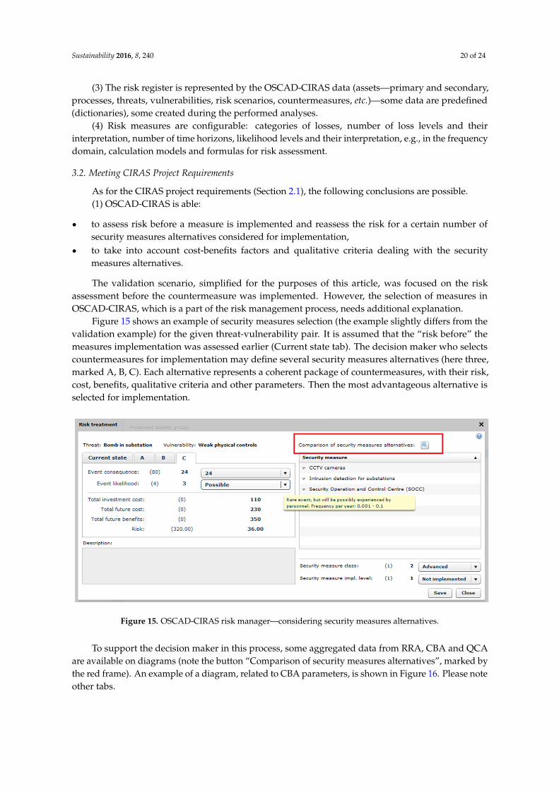
The objective was to perform a case study and to acquire knowledge for the CIRAS project.The question is to what extent the requirements are satisfied by OSCAD-CIRAS, i.e., whetherOSCAD-CIRAS is able to work as the risk reduction assessment (RRA) component within the CIRASTool. The ready-made OSCAD was configured, equipped with the domain data (dictionaries, measures,different parameters, etc.), and the validation was performed according to the elaborated plan. As aresult, the OSCAD-CIRAS experimentation tool was worked out.
3.1. Meeting Basic Requirements
Reviewing the basic requirements (Section 2.1.), the following conclusions are possible.(1) OSCAD-CIRAS takes into account the CI specific phenomena, such as common cause failures,
cascading and escalating effects, as well as interdependencies between CIs, though OSCAD-CIRASshould be supported by a resilience analysis. During the validation experiment it was shown thatOSCAD-CIRAS is able to consider the following:
‚ common cause initiating events; for the given hazardous event BIA is able to detect hazardousevents, that are implied by the given hazardous event, in all dependent infrastructures bygenerating many outgoing EE-related risk scenarios; this possibility was mentioned in Figure 14(Ele => RaT, Ele => Oil, Ele => Gas) but was shown only for one dependency path (Ele => RaT);
‚ cascade initiating events; apart from internally triggered hazardous events, the RA analysisconsiders external triggers incoming from other infrastructures as the incoming EE-related riskscenarios; the considered impacted CI depends on infrastructures which generate these scenarios;this possibility is represented by the following analyses:
‚ “2ee RA(Ele:Energy)”—a coal delivery problem may disturb the energy production process;‚ “3ee RA (RaT:Energy)”—an energy delivery problem may disturb railway transport;‚ cascade resulting events; BIA is able to detect any hazardous event resulting from
the original event which impacts a dependent infrastructure; this was represented by:“1 BIA(RaT:Node)”/Figure 10, “2ee BIA(Ele:Energy)”/Figure 14 and “3ee BIA (RaT:Energy)”(not shown);
‚ escalating events; BIA performed in the first infrastructure is able to detect a hazardous eventin the second impacted dependent infrastructure, and BIA performed for the second impactedinfrastructure is able to detect a hazardous event in the third infrastructure, and so on; this wasexemplified by the analysis chain for RaT => Ele => RaT (Figure 7—a red line).
(2) The bow-tie concept embracing the analysis of consequences and causes was implemented asthe pairs of the RA-BIA analyses. It was exemplified by the analyses chain shown in Figure 7. UsuallyBIA precedes RA.
Sustainability 2016, 8, 240 20 of 24
(3) The risk register is represented by the OSCAD-CIRAS data (assets—primary and secondary,processes, threats, vulnerabilities, risk scenarios, countermeasures, etc.)—some data are predefined(dictionaries), some created during the performed analyses.
(4) Risk measures are configurable: categories of losses, number of loss levels and theirinterpretation, number of time horizons, likelihood levels and their interpretation, e.g., in the frequencydomain, calculation models and formulas for risk assessment.
3.2. Meeting CIRAS Project Requirements
As for the CIRAS project requirements (Section 2.1), the following conclusions are possible.(1) OSCAD-CIRAS is able:
‚ to assess risk before a measure is implemented and reassess the risk for a certain number ofsecurity measures alternatives considered for implementation,
‚ to take into account cost-benefits factors and qualitative criteria dealing with the securitymeasures alternatives.
The validation scenario, simplified for the purposes of this article, was focused on the riskassessment before the countermeasure was implemented. However, the selection of measures inOSCAD-CIRAS, which is a part of the risk management process, needs additional explanation.
Figure 15 shows an example of security measures selection (the example slightly differs from thevalidation example) for the given threat-vulnerability pair. It is assumed that the “risk before” themeasures implementation was assessed earlier (Current state tab). The decision maker who selectscountermeasures for implementation may define several security measures alternatives (here three,marked A, B, C). Each alternative represents a coherent package of countermeasures, with their risk,cost, benefits, qualitative criteria and other parameters. Then the most advantageous alternative isselected for implementation.
Sustainability 2016, 8, 240 20 of 24
(2) The bow‐tie concept embracing the analysis of consequences and causes was implemented
as the pairs of the RA‐BIA analyses. It was exemplified by the analyses chain shown in Figure 7.
Usually BIA precedes RA.
(3) The risk register is represented by the OSCAD‐CIRAS data (assets—primary and secondary,
processes, threats, vulnerabilities, risk scenarios, countermeasures, etc.)—some data are predefined
(dictionaries), some created during the performed analyses.
(4) Risk measures are configurable: categories of losses, number of loss levels and their
interpretation, number of time horizons, likelihood levels and their interpretation, e.g., in the
frequency domain, calculation models and formulas for risk assessment.
3.2. Meeting CIRAS Project Requirements
As for the CIRAS project requirements (Section 2.1), the following conclusions are possible.
(1) OSCAD‐CIRAS is able:
to assess risk before a measure is implemented and reassess the risk for a certain number of
security measures alternatives considered for implementation,
to take into account cost‐benefits factors and qualitative criteria dealing with the security
measures alternatives.
The validation scenario, simplified for the purposes of this article, was focused on the risk
assessment before the countermeasure was implemented. However, the selection of measures in
OSCAD‐CIRAS, which is a part of the risk management process, needs additional explanation.
Figure 15 shows an example of security measures selection (the example slightly differs from the
validation example) for the given threat‐vulnerability pair. It is assumed that the “risk before” the
measures implementation was assessed earlier (Current state tab). The decision maker who selects
countermeasures for implementation may define several security measures alternatives (here three,
marked A, B, C). Each alternative represents a coherent package of countermeasures, with their risk,
cost, benefits, qualitative criteria and other parameters. Then the most advantageous alternative is
To support the decision maker in this process, some aggregated data from RRA, CBA and QCAare available on diagrams (note the button “Comparison of security measures alternatives”, marked bythe red frame). An example of a diagram, related to CBA parameters, is shown in Figure 16. Please noteother tabs.
More detailed graphs, tables, reports related to particular alternatives will be available fromthe CIRAS tool level. Currently they are under development. OSCAD-CIRAS is able to exchange(through developed web services) information with the CBA and QCA components during the decisionprocess dealing with the security measures selection
(2) Other issues related to the project requirements were discussed previously, like the ability toconsider the CI specific phenomena and cross-sectoral dependencies, to analyze causes and impacts ofhazardous events, and to manage the risk register data.
Reassuming, the validation process is based on the planned scenario which encompasses twocritical infrastructures: railway transport (RaT) and electricity provision (Ele). Two kinds of escalationeffects are demonstrated:
‚ those propagated through a CI internal path,‚ those propagated through a path crossing one or more CIs.
The consequences of hazardous events in a given CI can impact the same CI again and/or theneighboring CIs, creating a complex sequence of impacts. The presented method allows to identify:
‚ direct consequences occurring within the considered infrastructure (called here: CI degradation);‚ secondary effects caused by breaching internal barriers (CI safeguards) and occurring in this CI
as the consequences of a hazardous event (called here: internal escalation); this escalation canpropagate further causing additional hazardous events—internal or external;
‚ secondary effects occurring in the external CIs as the consequences of a hazardous event(called here: external escalation); they can propagate further, impacting other CIs or generatinginternal escalations.
The scenario depends on the new risks identified during the analysis. The presented methodassumes (in the loss matrix for BIA analyses) that a new hazardous event (internal or external) canbe triggered as a consequence of a previous hazardous event. Internally triggered events result from
Sustainability 2016, 8, 240 22 of 24
breaching the CI internal barriers. Events triggered within the external CIs can propagate thanks toexisting CI interdependencies. The risk assessment results give information if the hazardous event willpropagate internally and/or externally, or nowhere. It means that each risk situation may drive quite adifferent scenario in the same set of infrastructures. If, during the analysis of infrastructure A, it wasdetected that a breach in infrastructure B is possible (EE), then the risk analysis in infrastructure B isneeded and will be added to the risk analyses scenario. Otherwise, the analysis in infrastructure B willnot be added to this scenario. If, during the analysis of infrastructure A, it was detected that a securitybarrier can be breached (IE), then the analysis in infrastructure A is needed and will be added to therisk analyses scenario. Otherwise, it will not be added to this scenario.
For this reason, each scenario is here called a risk-driven scenario. It is assumed thatinterdependencies are known—all paths with possible propagation of impacts are known.
4. Conclusions
The objective of the paper is to develop a structured risk management method for criticalinfrastructures, embedded into the CI resilience process (Figure 6). The method distinguishes threecategories of impacts composed into the BIA loss matrix:
‚ CID (direct CI degradation),‚ IE (escalation by breaching internal security barriers),‚ EE (escalation by breaching security barriers in external CIs).
The method is based on the commonly used risk management methodology, though it wasenhanced by three above mentioned features which allowed to take into account the following issues(Section 3):
‚ how a hazardous event which occurred in the given CI impacts the dependent CIs; this allows toconsider common cause initiating events, cascade resulting events, externally escalating events;
‚ how a hazardous event which occurred in external CIs impacts the given CI; this allows to considercascade initiating events, externally escalating events;
‚ secondary impacts of a hazardous event which occurred in the given CI and lead to an internalescalation; this allows to analyze breaches in the multilayered protection system.
There are some extra features which make it possible to assess a critical infrastructure degradationin several time horizons (CID-type consequences). In addition, they can assess several securitymeasures packages with respect to the risk reduction ability.
To elaborate, implement and validate this method, the research includes as well:
‚ the identification of CI domain-related data, like assets, processes, threats, vulnerabilities, commonused countermeasures, etc., and put them into the OSCAD system dictionaries,
‚ the risk parameters definition, i.e.,: scales of measures for likelihood, consequences, impactscategories and levels, loss matrix, calculation formulas configuration,
‚ the planning of the validation scenario (to be simple enough and be able to exemplify all featuresof the elaborated method),
‚ performing validation to assess the feasibility of the proposed solution.
The paper gives substantial contribution to the CIRAS project. The aim of the research presentedin the paper is to acquire knowledge about the shape of the key component responsible for riskassessment (RRA) of the CIRAS Tool. The case study was based on the ready-made businesscontinuity/information security management OSCAD software. During the research this softwarewas adapted to the critical infrastructure application domain, according to the identified requirements.This way the dedicated OSCAD-CIRAS tool was developed. The near real data were prepared for thecritical infrastructure domain and the software was configured. According to the planned validationscenario, the risk assessment within two collaborating infrastructures (railway, energy) was studied.
Sustainability 2016, 8, 240 23 of 24
The case study gives information how to use OSCAD-CIRAS in the CIRAS project. The results ofresearch confirm that OSCAD-CIRAS can be applied as the RRA component.
The acquired knowledge was used by the CIRAS project team. Currently all components(RRA, CBA, QCA) are integrated into the CIRAS Tool. The case study described in the paper isthe basis for two CIRAS project use cases.
The CIRAS project considerably extends the risk reduction assessment by additional CBA(cost-benefits) and QCA (vague factors) assessments to obtain a full risk picture for the decision maker.
Acknowledgments: The author thanks his Colleagues from the CIRAS project consortium for reviewing this paperand discussing the presented concept. The author is grateful for their assistance during the OSCAD customization(installation, logo edition, preparing the OSCAD dictionaries).
Author Contributions: The presented validation experiment represent the author’s own research.
Conflicts of Interest: The author declares no conflict of interest. The OSCAD is owned by the Institute ofInnovative Technologies EMAG. This project has been funded with support from the European Commission.This publication reflects the views only of the author, and the European Commission cannot be held responsible forany use which may be made of the information contained therein (obligatory for each paper concerning CIRAS).
References and Notes
1. Eusgeld, I.; Nan, C.; Dietz, S. “System-of-systems” approach for interdependent critical infrastructures.Reliab. Eng. Syst. Saf. 2011, 96, 679–686. [CrossRef]
2. ISO. Risk management—Principles and guidelines; ISO 31000:2009; International Organization forStandardization: Geneva, Switzerland, 2009.
3. IEC/ISO. Risk Management—Risk Assessment Techniques; IEC 31010:2009; International ElectrotechnicalCommission (in cooperation with ISO): Geneva, Switzerland, 2009.
4. Hokstad, P.; Utne, I.B.; Vatn, J. Risk and Interdependencies in Critical Infrastructures: A Guideline for Analysis,Reliability Engineering; Springer-Verlag: London, UK, 2012.
6. Giannopoulos, G.; Filippini, R. Risk Assessment and Resilience for Critical Infrastructures.In Proceedings of Workshop Proceedings, Ispra, Italy, 25–26 April 2012; Available online:http://publications.jrc.ec.europa.eu/repository/handle/JRC71923 (accessed on 29 February 2016).
7. Min, H.-S. J.; Beyeler, W.; Brown, T.; Jun Son, Y.; Jones, A.T. Toward modelling and simulation of criticalnational infrastructure interdependencies. IIE Trans. 2007, 39, 57–71. [CrossRef]
8. The Council of the European Union. Council Directive 2008/114/EC—on the identification and designationof European critical infrastructures and the assessment of the need to improve their protection. 2008.Available online: http://eur-lex.europa.eu/legal-content/EN/TXT/?uri=CELEX%3A32008L0114 (accessedon 29 February 2016).
9. European Commission. Commission Staff Working Document—on a new approach to the EuropeanProgramme for Critical Infrastructure Protection Making European Critical Infrastructures more secure. 2013.Available online: https://ec.europa.eu/energy/sites/ener/files/documents/20130828_epcip_commission_staff_working_document.pdf (accessed on 29 February 2016).
10. CIRAS project web site. Available online: http://cirasproject.eu/content/project-topic (accessed on22 December 2015).
11. ValueSec FP7 project web site. Available online: www.valuesec.eu (accessed on 22 December 2015).12. Bialas, A. Critical infrastructures risk manager—the basic requirements elaboration. In Theory and
Engineering of Complex Systems and Dependability; Zamojski, W., Mazurkiewicz, J., Sugier, J., Walkowiak, T.,Kacprzyk, J., Eds.; Springer-Verlag: Cham, Switzerland; Heidelberg, Germany; New York, NY, USA;Dordrecht, The Netherland; London, UK, 2015; pp. 11–24.
13. EMAG. OSCAD project web site. Available online: http://www.oscad.eu/index.php/en/ (accessed on21 December 2015).
14. Giannopoulos, G.; Filippini, R.; Schimmer, M. Risk Assessment Methodologies for Critical InfrastructureProtection—Part I: A State of the Art; Publications Office of the European Union: Luxembourg, 2012.
15. European Commission. EURACOM Deliverable D20: Final Publishable Summary, Version: D20.1. 2011.Available online: http://cordis.europa.eu/result/rcn/57042_en.html (accessed on 21 December 2015).
16. ENISA. Inventory of Risk Management/Risk Assessment Methods and Tools. Available online:http://rm-inv.enisa.europa.eu/methods (accessed on 21 December 2015).
17. Baginski, J.; Bialas, A.; Rogowski, D.; Flisiuk, B.; (Institute of Innovative Technologies EMAG, Katowice,Poland); Martin, J.; Garcia, A.; (ATOS S.A., Madrid, Spain); Klein, P.; (Center for European Security Strategies,Munich, Germany). State of the Art of Methods and Tools. 2015.
18. Rausand, M. Risk Assessment: Theory, Methods, and Applications. In Statistics in Practice; Wiley: Hoboken,NJ, USA, 2011.
19. Białas, A. Risk assessment aspects in mastering the value function of security measures. In NewResults in Dependability and Computer Systems; Zamojski, W., Mazurkiewicz, J., Sugier, J., Walkowiak, T.,Kacprzyk, J., Eds.; Springer-Verlag: Cham, Switzerland; Heidelberg, Germany; New York, NY, USA;Dordrecht, The Netherland; London, UK, 2013.
20. Bialas, A. Computer support for the railway safety management system—first validation results.In Advances in Intelligent Systems and Computing; Zamojski, W., Mazurkiewicz, J., Sugier, J., Walkowiak, T.,Kacprzyk, J., Eds.; Springer-Verlag: Cham, Switzerland; Heidelberg, Germany; New York, NY, USA;Dordrecht, The Netherland; London, UK, 2014.
21. Białas, A. Business continuity management, information security and assets management in mining.Mechanizacja i Automatyzacja Górnictwa 2013, 8, 125–138. Available online: http://yadda.icm.edu.pl/yadda/element/bwmeta1.element.baztech-891910b0-6f4e-4dfb-8bc3-345d940cc88b?q=fd72cbbb-7631-435b-9e4e-cf0b5ebdcc38$4&qt=IN_PAGE (accessed on 29 February 2016).
22. OSCAD-CIRAS. Available online on request using the author’s e-mail.23. Białas, A. Experimentation tool for critical infrastructures risk management. In Proceedings of the
2015 Federated Conference on Computer Science and Information Systems (FedCSIS), Lodz, Poland,13–16 September 2015.