+ All Categories
Home > Documents > RiskFactor.pdf

RiskFactor.pdf

Date post: 02-Apr-2018
Category:
Upload: alexander-wijesooriya
View: 224 times
Download: 0 times
Share this document with a friend
12
 MODULE 3 EVALUATING ELECTRICAL RISK FACTORS  Recognize Evaluate Control Recognize Recognize Evaluate Evaluate Control Control  At the end of this module, you will be able to… Recognize the purpose and various methods for evaluating arc flash. Identify arc flash approach boundaries and their meaning. List the steps for conducting a task analysis. Recognize how to conduct a fall hazard evaluation. Given a case study, analyze the hazards and recommend improvements. Prevention Strategies for Electrical Hazards © 2008 National Safety Council  1
Transcript

7/27/2019 RiskFactor.pdf

http://slidepdf.com/reader/full/riskfactorpdf 1/12


MODULE 3EVALUATING ELECTRICAL RISK FACTORS


Recognize Evaluate ControlRecognizeRecognize EvaluateEvaluate ControlControl


At the end of this module, you will be able to…

Recognize the purpose and various methods for evaluating arc flash.

Identify arc flash approach boundaries and their meaning.

List the steps for conducting a task analysis.

Recognize how to conduct a fall hazard evaluation.

Given a case study, analyze the hazards and recommend improvements.

Prevention Strategies for Electrical Hazards

© 2008 National Safety Council  1

7/27/2019 RiskFactor.pdf

http://slidepdf.com/reader/full/riskfactorpdf 2/12

 MODULE 3 P ARTICIPANT GUIDE 

Electrical Hazard Analysis

When electrical components operate at 50 volts nominal and above, workers should de-

energize the equipment when they work on it. This means that it should be locked out,

tagged out, and then tested to ensure that it is indeed de-energized. The qualified person

 performing these functions should be outfitted in the appropriate PPE.

If the components cannot be de-energized because of the nature of the work to be performed

or because of an increased risk posed by de-energizing, then a Shock Hazard Analysis and a

Flash Hazard Analysis need to be performed.

There are three desired outputs for these evaluations.

1.  To determine flash protection boundaries

2.  To determine incident energy

3.  To determine the hazard/risk category for PPE selection

NFPA Evaluations

Evaluation Type: Shock Hazard Analysis

NFPA Definition: A Shock Hazard Analysis shall determine the voltage to which personnel

will be exposed, boundary requirements, and the personal protective equipment necessary in

order to minimize the possibility of electric shock to personnel. To determine shock hazard,

a licensed electrical engineer will perform either a calculation or use Table 130.2(C) of 

 NFPA 70E.

NFPA Reference: 70E 130.2

Who Conducts Evaluation: Licensed Electrical Engineer 

Evaluation Type: Flash Hazard Analysis

NFPA Definition: A Flash Hazard Analysis shall be done in order to protect personnel from

the possibility of being injured by an arc flash. The analysis shall determine the flash

 protection boundary and the personal protective equipment that people within the flash

 protection boundary shall use.

NFPA Reference: 70E 130.3

Who Conducts Evaluation: Licensed Electrical Engineer 

2 Prevention Strategies for Electrical Hazards

© 2008 National Safety Council 

7/27/2019 RiskFactor.pdf

http://slidepdf.com/reader/full/riskfactorpdf 3/12

P ARTICIPANT GUIDE MODULE 3

Methods for Evaluating Arc Flash

There are many methods for evaluating arc flash. Unless you are a Licensed Electrical

Engineer, you will not be making these calculations. However, it may be helpful for you to

 be familiar with the different methods.

NFPA 70E equations andtables

Annex D of NFPA provides equations and tables

for calculating arc flash.

These equations are not part of NFPA

requirements, but are provided for information.

Institute of Electrical and

Electronics Engineers

(IEEE) Standard 1584

Standard 1584 provides definitive calculation

steps to support the NFPA standard for arc flash

calculations.

It outlines a method for calculating the anticipatedincident energy.

Software programs There are numerous software programs that can

 be used by licensed electrical engineers to

calculate arc flash.

These programs base their calculations on the

 NFPA equations and the IEEE 1584 standard.

Electrical System Analysis This is an electrical system engineering study that

is performed by engineers familiar with the power 

distribution and control equipment and the

calculation methods required. The arc flash

analysis will determine, among other things, the

incident energy potential of each piece of 

electrical distribution equipment in the facility.

This incident energy potential will define the

Hazard/Risk Category of PPE that the employee

is required to wear while performing any work 

when energized.

Dc = [2.65 X MVAbf X t]1/2Dc = [2.65 X MVAbf X t]1/2


Prevention Strategies for Electrical Hazards

© 2008 National Safety Council  3

7/27/2019 RiskFactor.pdf

http://slidepdf.com/reader/full/riskfactorpdf 4/12

 MODULE 3 P ARTICIPANT GUIDE 

Limits of Approach

The qualified person will adhere to approach limits based on the type of equipment and the

voltage of the system. This diagram illustrates the boundaries that will be used by the

qualified person when working with energized components. Note that the outermost

 boundary is for flash protection. All of the inner boundaries are for shock protection.

Exposed Energized Part

Prohibited Approach Boundary

Flash Protection Boundary

Restricted Approach Boundary Limited Approach Boundary

Exposed Energized Part

Prohibited Approach Boundary

Flash Protection Boundary

Restricted Approach Boundary Limited Approach Boundary  

Boundary Meaning

Flash protection

 boundaryThis is the outer boundary of the flash protection zone.

Employees passing it must wear flash protective equipment.

Limited approach

 boundaryA person crossing this line must be qualified to do the job/task.

They must wear flash protective equipment.

Unqualified workers are prohibited from crossing this boundary.

Restricted approach

 boundary

A person crossing this line enters into restricted space.

Only qualified people may cross this boundary.

Qualified people must have a written plan that is approved by

authorized management.

They must use PPE appropriate for working near energized

 parts.

They must ensure no body part crosses the prohibited line and

keep as much of their body out of the restricted space as

 possible.

Prohibited approach

 boundary

Crossing this line is the same as having contact with the live

 part.

Only qualified people may cross this line.

They must have specified training to work on energized parts.

They must have a documented plan and a risk hazard analysis

that are approved by authorized management.

They must wear PPE appropriate for working on live parts.

4 Prevention Strategies for Electrical Hazards

© 2008 National Safety Council 

7/27/2019 RiskFactor.pdf

http://slidepdf.com/reader/full/riskfactorpdf 5/12

P ARTICIPANT GUIDE MODULE 3

Using the NFPA Tables

There may be occasions when electrical work must begin before the Flash Hazard and Shock 

Hazard Analyses are complete. In these instances, the workers must still wear PPE. NFPA

has provided tables to help determine which PPE is required when the calculations have not

 been done. Keep in mind that the data in the NFPA tables tends to be conservative.

Following is a sample of the information provided in the NFPA 70E tables. Please note that

this is an excerpt from the tables and only a sample. When these tables are used, ALL 

corresponding notes must be taken into consideration.

Task Hazard/Risk

Category

V-Rated

Gloves

V-Rated

Tools

Panelboards rated 240v and below

Circuit breaker (CB) or fused switch

operation with covers on

Work on energized parts, including

voltage testing

Remove or install circuit breakers or fused

switches

0

1

1

 N

Y

Y

 N

Y

Y

600v Class Motor Control CentersWork on energized parts, including

voltage testing

Insertion or removal of individual starter 

“buckets” from the motor control

center 

Application of safety grounds, after 

voltage test

2*

3

3

Y

Y

Y

Y

 N

 N

*A double-layer switching hood and hearing protection are required for this task in addition

to other Category 2 requirements.

Table Source: NFPA 70E Table 130.7(C)(9)(a)

Prevention Strategies for Electrical Hazards

© 2008 National Safety Council  5

7/27/2019 RiskFactor.pdf

http://slidepdf.com/reader/full/riskfactorpdf 6/12

 MODULE 3 P ARTICIPANT GUIDE 

Steps for Task Analysis

The most effective way to evaluate the potential risk of a job or project that involves

electricity is to perform a task analysis of the job. The task analysis allows you to determine

where the electrical hazards are in the job. Here are the steps for performing a task analysis.

1.  Involve everyone who will be working on the job/project.

2.  Identify every step that must be taken to complete the job/project. 

3.  For each step, identify the electrical procedures that will be performed. 

4.  Obtain or create drawings and other documents pertaining to the electrical system(s) that

will be involved. 

5.  Identify the hazards associated with the job/project. 

Fall Chemical 

Electric shock  

Burn 

Arc flash 

6.  Agree on safety procedures that everyone will follow. 

Lockout/tagout 

Guarding 

Approach limitations 

PPE 

Signage 

7.  Determine the proper tools that need to be used for the job/project. 

8.  Determine the PPE that must be used for the job/project. 

Note: This list is available on your Tools and Resources CD-ROM.

6 Prevention Strategies for Electrical Hazards

© 2008 National Safety Council 

7/27/2019 RiskFactor.pdf

http://slidepdf.com/reader/full/riskfactorpdf 7/12

P ARTICIPANT GUIDE MODULE 3

Evaluating Fall Hazards

If electrical work requires working at height (roof or ceiling work, tree trimming), it is

important to evaluate the potential hazards that could cause a fall in the event of an electrical

incident. Following are some of the items that should be evaluated prior to the job/project.

Item to Evaluate Yes No

Is there a proper scaffold or work platform? 

  Is the scaffold or work platform of a non-conductive material? 

  Does the work platform have proper guardrailing (top edge height

 between 39 and 45 inches)?  

  Does scaffold or work platform have screens or mesh to protect tools

from falling into or near the electrical system?  

  If a ladder is used, is it of non-conductive material? 

  Does scaffold have toe boards to prevent tools and other loose

equipment from falling?  

  On a suspension or scissor scaffold, are electrical wires properly

insulated and free of damage?


  Is there adequate clearance between the scaffold or ladder and power 

lines?  

  Is the scaffold free of dust and debris? 

  Are fall arrest systems used? 

  Is the scaffold or ladder free of moisture, snow and ice?


Note: This checklist is available on your Tools and Resources CD-ROM.

Prevention Strategies for Electrical Hazards

© 2008 National Safety Council  7

7/27/2019 RiskFactor.pdf

http://slidepdf.com/reader/full/riskfactorpdf 8/12

 MODULE 3 P ARTICIPANT GUIDE 

Activity: Case Study

Directions: Read the case study, then complete the following worksheet. This is a

summary of an incident that actually happened

Background of the Incident

The incident occurred at a large, cosmetic packaging plant in an urban-industrial area. The

 plant specialized in manufacturing plastic inserts for protecting and displaying the products.

Most of this manufacturing was done in the thermoforming department, a large room with 13

industrial thermoforming machines. Sheets of plastic were fed into the machine and pressed

 between two large, heated dies. The dies created multiple impressions of the form in the

 plastic, each of which were cut out in the next production step. Cosmetics or other items

were placed into the plastic insert, which was then placed into the box to make the final

 package.

The residual heat created by the thermoforming machines caused the room to becomeuncomfortably warm for employees, so management decided to install large exhaust fans in

the walls. The fans would redistribute the heat from the thermoforming room into the plant’s

adjoining warehouse. Plant employees were to install most of the non-live wiring, and an

electrical contractor was hired to do the actual electrical connections. Management assigned

the plant’s mechanic to do the non-live wiring. The mechanic was a 21-year-old Hispanic

male who was responsible for performing maintenance and minor repairs on the

thermoforming machines. Assisting him was a laborer (the victim) who was being trained as

a mechanic’s assistant. Both workers had been hired on the same day in November, 2002.

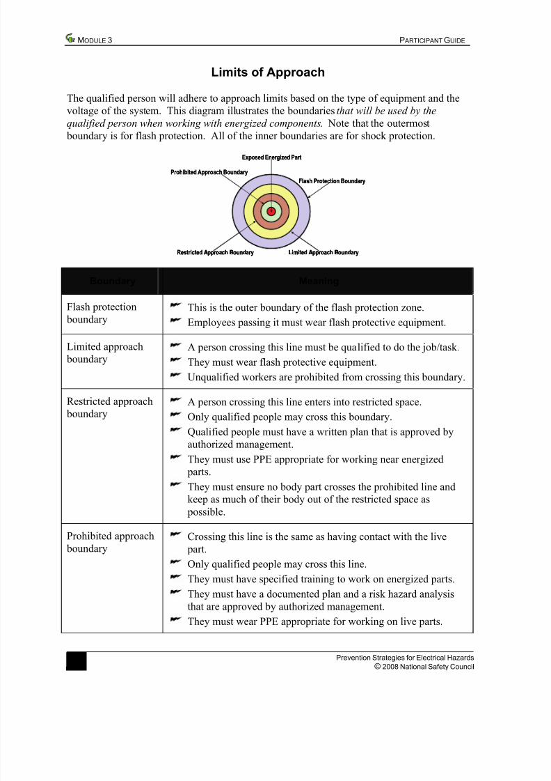
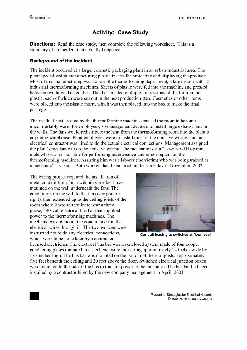
The wiring project required the installation of 

metal conduit from four switching/breaker boxesmounted on the wall underneath the fans. The

conduit ran up the wall to the fans (see photo at

right), then extended up to the ceiling joists of the

room where it was to terminate near a three-

 phase, 480-volt electrical bus bar that supplied

 power to the thermoforming machines. The

mechanic was to mount the conduit and run the

electrical wires through it. The two workers were

instructed not to do any electrical connections,

which were to be done later by a contractedConduit leading to switches at floor level 

licensed electrician. The electrical bus bar was an enclosed system made of four copper conducting plates mounted in a steel enclosure measuring approximately 14 inches wide by

five inches high. The bus bar was mounted on the bottom of the roof joists, approximately

five feet beneath the ceiling and 20 feet above the floor. Switched electrical junction boxes

were mounted to the side of the bus to transfer power to the machines. The bus bar had been

installed by a contractor hired by the new company management in April, 2003.

8 Prevention Strategies for Electrical Hazards

© 2008 National Safety Council 

7/27/2019 RiskFactor.pdf

http://slidepdf.com/reader/full/riskfactorpdf 9/12

P ARTICIPANT GUIDE MODULE 3

Activity: Case Study—continued

Background of the Incident—continued

The incident occurred the afternoon of Wednesday,

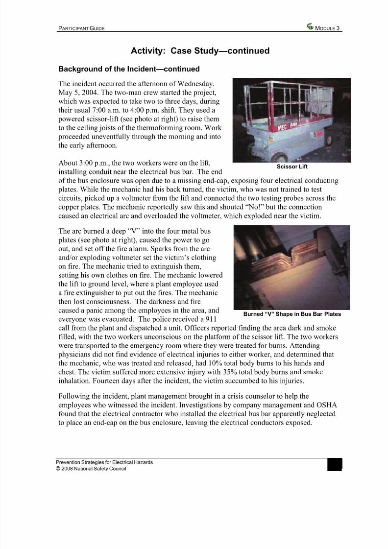
May 5, 2004. The two-man crew started the project,which was expected to take two to three days, during

their usual 7:00 a.m. to 4:00 p.m. shift. They used a

 powered scissor-lift (see photo at right) to raise them

to the ceiling joists of the thermoforming room. Work 

 proceeded uneventfully through the morning and into

the early afternoon.

About 3:00 p.m., the two workers were on the lift,

installing conduit near the electrical bus bar. The endScissor Lift 

of the bus enclosure was open due to a missing end-cap, exposing four electrical conducting

 plates. While the mechanic had his back turned, the victim, who was not trained to testcircuits, picked up a voltmeter from the lift and connected the two testing probes across the

copper plates. The mechanic reportedly saw this and shouted “No!” but the connection

caused an electrical arc and overloaded the voltmeter, which exploded near the victim.

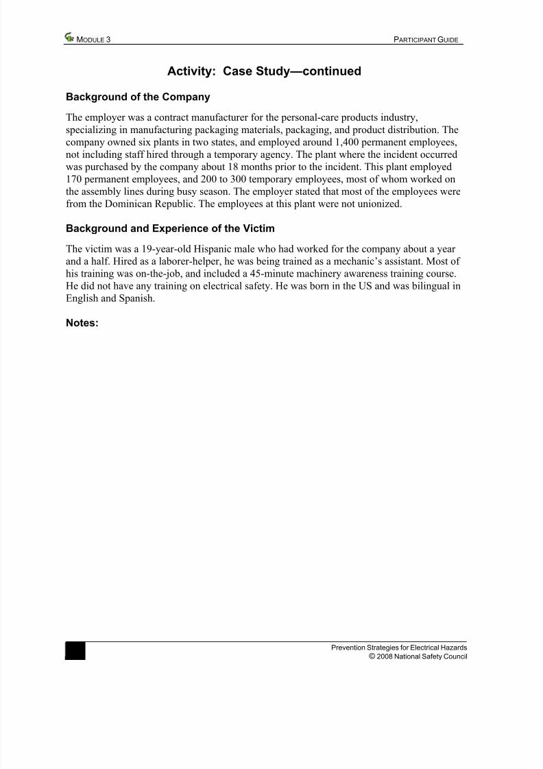
The arc burned a deep “V” into the four metal bus

 plates (see photo at right), caused the power to go

out, and set off the fire alarm. Sparks from the arc

and/or exploding voltmeter set the victim’s clothing

on fire. The mechanic tried to extinguish them,

setting his own clothes on fire. The mechanic lowered

the lift to ground level, where a plant employee used

a fire extinguisher to put out the fires. The mechanic

then lost consciousness. The darkness and fire

caused a panic among the employees in the area, and

everyone was evacuated. The police received a 911Burned “V” Shape in Bus Bar Plates 

call from the plant and dispatched a unit. Officers reported finding the area dark and smoke

filled, with the two workers unconscious on the platform of the scissor lift. The two workers

were transported to the emergency room where they were treated for burns. Attending

 physicians did not find evidence of electrical injuries to either worker, and determined that

the mechanic, who was treated and released, had 10% total body burns to his hands and

chest. The victim suffered more extensive injury with 35% total body burns and smoke

inhalation. Fourteen days after the incident, the victim succumbed to his injuries.

Following the incident, plant management brought in a crisis counselor to help the

employees who witnessed the incident. Investigations by company management and OSHA

found that the electrical contractor who installed the electrical bus bar apparently neglected

to place an end-cap on the bus enclosure, leaving the electrical conductors exposed.

Prevention Strategies for Electrical Hazards

© 2008 National Safety Council  9

7/27/2019 RiskFactor.pdf

http://slidepdf.com/reader/full/riskfactorpdf 10/12

7/27/2019 RiskFactor.pdf

http://slidepdf.com/reader/full/riskfactorpdf 11/12

P ARTICIPANT GUIDE MODULE 3

Activity: Case Study—continued

Directions: In your group, analyze the case on the previous pages, then answer the

following questions.

1.  What hazards were present in this situation?

2.  What did the management and employees do wrong?

3.  How could an incident like this have been prevented?

Prevention Strategies for Electrical Hazards

© 2008 National Safety Council  11 

7/27/2019 RiskFactor.pdf

http://slidepdf.com/reader/full/riskfactorpdf 12/12

 MODULE 3 P ARTICIPANT GUIDE 

12 Prevention Strategies for Electrical Hazards

© 2008 National Safety Council 

Planning for Your Small Business

Directions: Based on what you’ve learned in this module, what will you do back on the job?

1.  Identify two or three actions you will take when you return to your worksite.

2.  In addition, identify the potential barriers you might encounter in taking these actions.3.   Next, list ideas for overcoming the barriers identified.

Action Plan

Action Potential Barriers Overcoming the Barriers