Features NEW AND IMPROVED MODEL! Cast Aluminium floodlight with glass diffuser Replaceable LED Panel IP54 MODEL # DESCRIPTION COLOUR GLOBE TYPE MX63011 1 Light LED Exterior Flood Light Beige, Black & Silver 9W LED MX63012 2 Light LED Exterior Flood Light Beige, Black & Silver 2 x 9W LED MX63011/SEN 1 Light LED Exterior Flood Light with Sensor Beige, Black & Silver 9W LED MX63012/SEN 2 Light LED Exterior Flood Light with Sensor Beige, Black & Silver 2 x 9W LED Dimensions 1 LT W: 15cm x H:19cm 1 LT Sensor W: 18 x H: 22cm 2 LT W: 32cm x H: 19cm 2 LT Sensor W: 32cm x H: 22cm RITZ MX6301 Visit us www.mercator.com.au MODEL WATTAGE LUMENS COLOUR TEMP DIMMABLE REPLACEABLE MX63011 9W 440lm 4000K No Yes MX63012 2 x 9W 850lm 4000K No Yes
Transcript
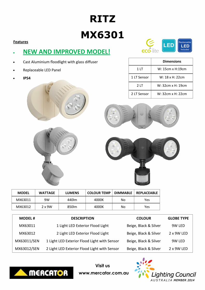
Features
NEW AND IMPROVED MODEL!
Cast Aluminium floodlight with glass diffuser
Replaceable LED Panel
IP54
MODEL # DESCRIPTION COLOUR GLOBE TYPE
MX63011 1 Light LED Exterior Flood Light Beige, Black & Silver 9W LED
MX63012 2 Light LED Exterior Flood Light Beige, Black & Silver 2 x 9W LED
MX63011/SEN 1 Light LED Exterior Flood Light with Sensor Beige, Black & Silver 9W LED
MX63012/SEN 2 Light LED Exterior Flood Light with Sensor Beige, Black & Silver 2 x 9W LED
Dimensions
1 LT W: 15cm x H:19cm
1 LT Sensor W: 18 x H: 22cm
2 LT W: 32cm x H: 19cm
2 LT Sensor W: 32cm x H: 22cm
RITZ
MX6301
Visit us
www.mercator.com.au
MODEL WATTAGE LUMENS COLOUR TEMP DIMMABLE REPLACEABLE
MX63011 9W 440lm 4000K No Yes
MX63012 2 x 9W 850lm 4000K No Yes
Fig. 3 Control Knob
TIMESENS LUX
FLOODLIGHT WITH INFRARED MOVEMENT SENSOR MODEL: RITZ – MX63011/SEN; MX63012/SEN
INTRODUCTION
The Mercator Ritz Sensor Floodlight incorporates a PIR (Passive Infra Red) sensing device
that continuously scans a preset operating area and immediately switches the light on
when it detects movement in that area.
When movement is detected within the range of the sensor the light will switch on
automatically, illuminating pathways, steps, patios, porches, or any other area selected to
light for reasons of safety, convenience or security. While there is movement within range of
the unit the light will remain on.
WHERE TO FIT YOUR FLOODLIGHT
To achieve best results, please note the following important points:
Sensor light should be mounted in a sheltered location (under an eave), to protect from
sun, wind and rain.
Do not mount the sensor light on a vibrational surface.
The sensor light should not be fitted in close proximity to fluorescent lights or ceiling
fans on the same electrical circuit, or other strong electromagnetic disturbance. Radio
Frequency Interference may cause the light to switch on inadvertently.
Ideally the security Light should be mounted 1.8 to 2.5 meters (6 to 8ft) above the area
to be scanned (refer Fig.1A).
The sensor should be directed slightly downwards and away from the sun to avoid
damage.
To avoid false operation of the sensor, ensure the sensor is not directed towards heat
sources such as barbecues, Air-conditioners, other outside lighting, moving cars and
flue vents.
Do not aim towards reflective surfaces such as smooth white walls, swimming pools, etc.
Always ensure that the sensor head and the light fitting are a minimum of 40mm apart to
ensure heat from the light does not activate the sensor.
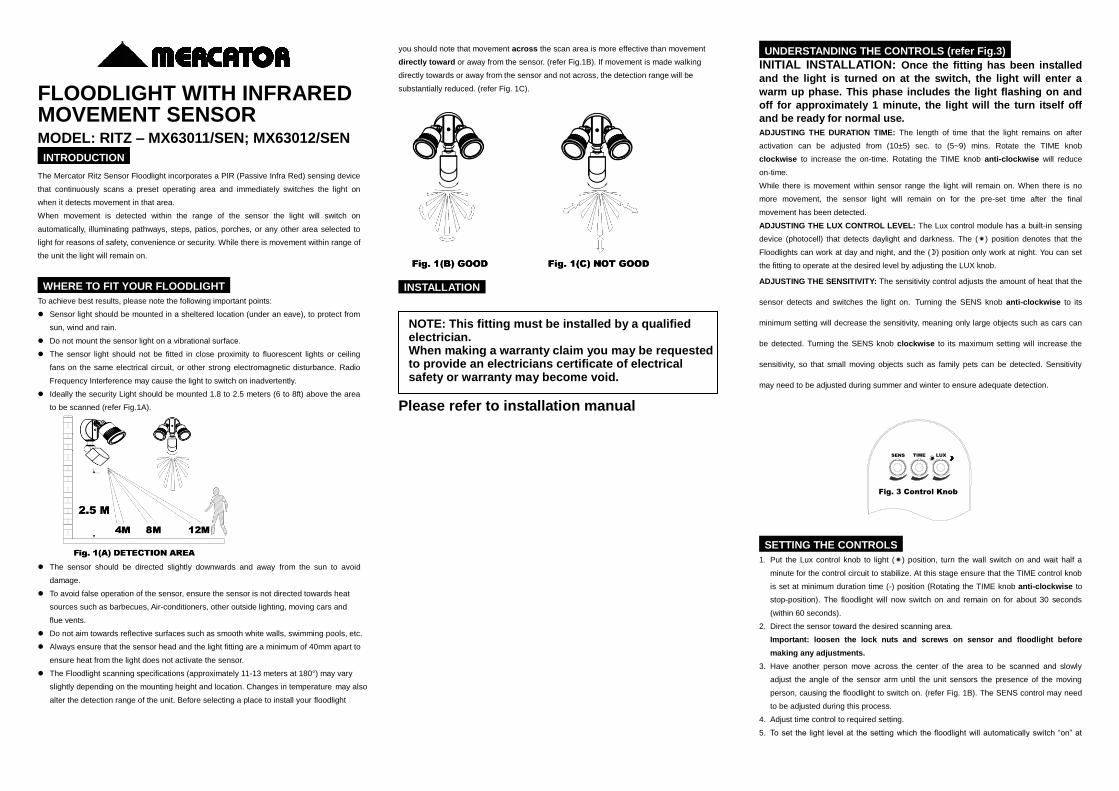
The Floodlight scanning specifications (approximately 11-13 meters at 180°) may vary
slightly depending on the mounting height and location. Changes in temperature may also
alter the detection range of the unit. Before selecting a place to install your floodlight
you should note that movement across the scan area is more effective than movement
directly toward or away from the sensor. (refer Fig.1B). If movement is made walking
directly towards or away from the sensor and not across, the detection range will be
substantially reduced. (refer Fig. 1C).
INSTALLATION
Please refer to installation manual
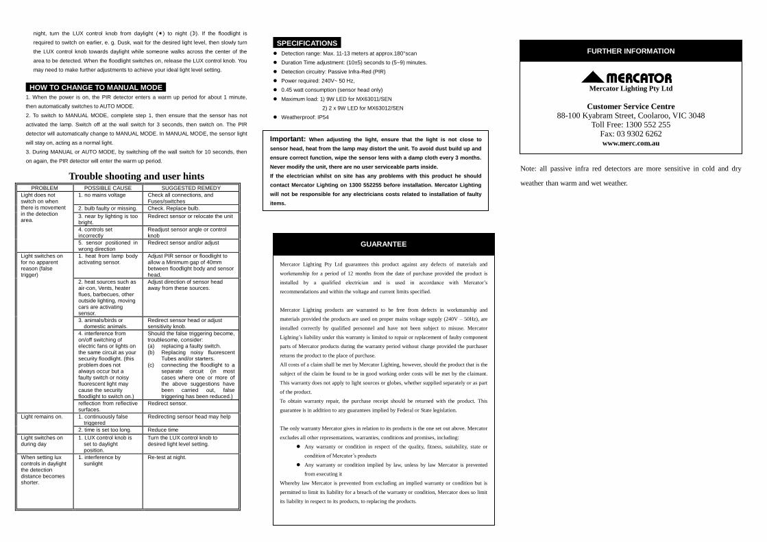
UNDERSTANDING THE CONTROLS (refer Fig.3)
INITIAL INSTALLATION: Once the fitting has been installed
and the light is turned on at the switch, the light will enter a
warm up phase. This phase includes the light flashing on and
off for approximately 1 minute, the light will the turn itself off
and be ready for normal use.
ADJUSTING THE DURATION TIME: The length of time that the light remains on after
activation can be adjusted from (10±5) sec. to (5~9) mins. Rotate the TIME knob
clockwise to increase the on-time. Rotating the TIME knob anti-clockwise will reduce
on-time.
While there is movement within sensor range the light will remain on. When there is no
more movement, the sensor light will remain on for the pre-set time after the final
movement has been detected.
ADJUSTING THE LUX CONTROL LEVEL: The Lux control module has a built-in sensing
device (photocell) that detects daylight and darkness. The () position denotes that the
Floodlights can work at day and night, and the () position only work at night. You can set
the fitting to operate at the desired level by adjusting the LUX knob.
ADJUSTING THE SENSITIVITY: The sensitivity control adjusts the amount of heat that the
sensor detects and switches the light on. Turning the SENS knob anti-clockwise to its
minimum setting will decrease the sensitivity, meaning only large objects such as cars can
be detected. Turning the SENS knob clockwise to its maximum setting will increase the
sensitivity, so that small moving objects such as family pets can be detected. Sensitivity
may need to be adjusted during summer and winter to ensure adequate detection.
SETTING THE CONTROLS
1. Put the Lux control knob to light () position, turn the wall switch on and wait half a
minute for the control circuit to stabilize. At this stage ensure that the TIME control knob
is set at minimum duration time (-) position (Rotating the TIME knob anti-clockwise to
stop-position). The floodlight will now switch on and remain on for about 30 seconds
(within 60 seconds).
2. Direct the sensor toward the desired scanning area.
Important: loosen the lock nuts and screws on sensor and floodlight before
making any adjustments.
3. Have another person move across the center of the area to be scanned and slowly
adjust the angle of the sensor arm until the unit sensors the presence of the moving
person, causing the floodlight to switch on. (refer Fig. 1B). The SENS control may need
to be adjusted during this process.
4. Adjust time control to required setting.
5. To set the light level at the setting which the floodlight will automatically switch “on” at
NOTE: This fitting must be installed by a qualified electrician. When making a warranty claim you may be requested to provide an electricians certificate of electrical safety or warranty may become void.
night, turn the LUX control knob from daylight () to night (). If the floodlight is
required to switch on earlier, e. g. Dusk, wait for the desired light level, then slowly turn
the LUX control knob towards daylight while someone walks across the center of the
area to be detected. When the floodlight switches on, release the LUX control knob. You
may need to make further adjustments to achieve your ideal light level setting.
HOW TO CHANGE TO MANUAL MODE
1. When the power is on, the PIR detector enters a warm up period for about 1 minute,
then automatically switches to AUTO MODE.
2. To switch to MANUAL MODE, complete step 1, then ensure that the sensor has not
activated the lamp. Switch off at the wall switch for 3 seconds, then switch on. The PIR
detector will automatically change to MANUAL MODE. In MANUAL MODE, the sensor light
will stay on, acting as a normal light.
3. During MANUAL or AUTO MODE, by switching off the wall switch for 10 seconds, then
on again, the PIR detector will enter the warm up period.
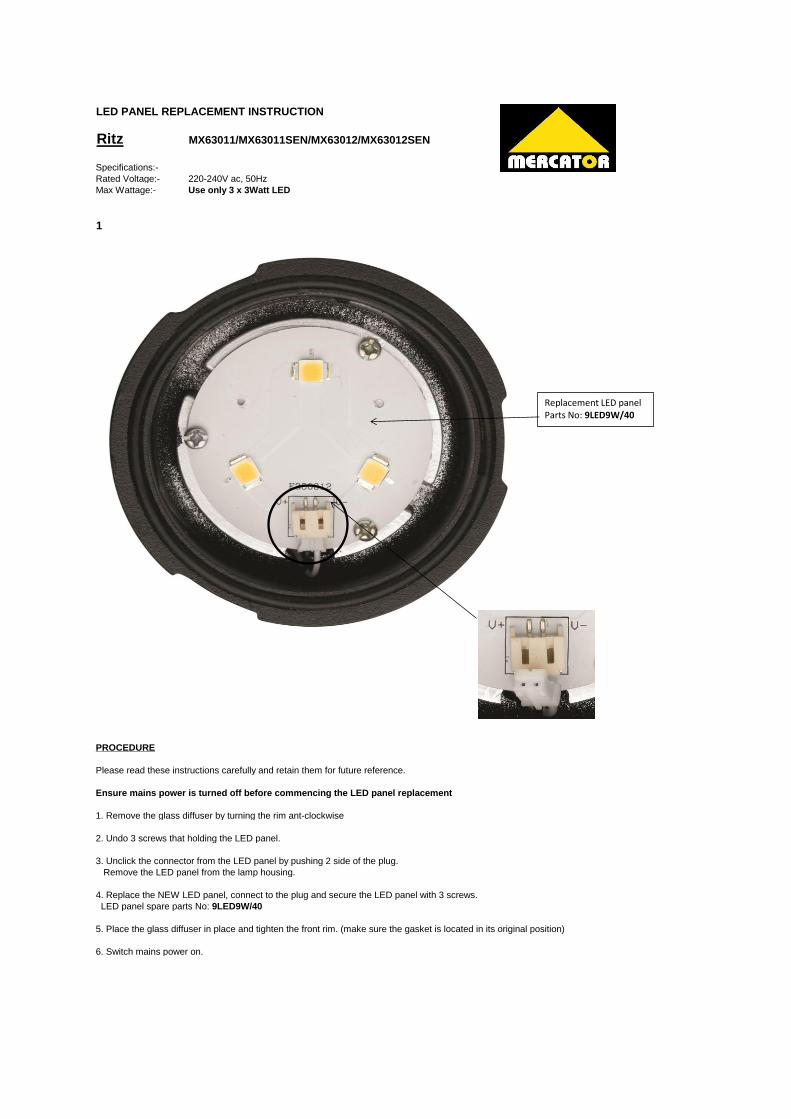
SPECIFICATIONS
Detection range: Max. 11-13 meters at approx.180°scan
Duration Time adjustment: (10±5) seconds to (5~9) minutes.
Detection circuitry: Passive Infra-Red (PIR)
Power required: 240V~ 50 Hz,
0.45 watt consumption (sensor head only)
Maximum load: 1) 9W LED for MX63011/SEN
2) 2 x 9W LED for MX63012/SEN
Weatherproof: IP54
Note: all passive infra red detectors are more sensitive in cold and dry
weather than warm and wet weather.
Trouble shooting and user hints PROBLEM POSSIBLE CAUSE SUGGESTED REMEDY
Light does not switch on when there is movement in the detection area.
1. no mains voltage Check all connections, and Fuses/switches
2. bulb faulty or missing. Check. Replace bulb.
3. near by lighting is too bright.
Redirect sensor or relocate the unit
4. controls set incorrectly
Readjust sensor angle or control knob
5. sensor positioned in wrong direction
Redirect sensor and/or adjust
Light switches on for no apparent reason (false trigger)
1. heat from lamp body activating sensor.
Adjust PIR sensor or floodlight to allow a Minimum gap of 40mm between floodlight body and sensor head.
2. heat sources such as air-con, Vents, heater flues, barbecues, other outside lighting, moving cars are activating sensor.
Adjust direction of sensor head away from these sources.
3. animals/birds or domestic animals.
Redirect sensor head or adjust sensitivity knob.
4. interference from on/off switching of electric fans or lights on the same circuit as your security floodlight. (this problem does not always occur but a faulty switch or noisy fluorescent light may cause the security floodlight to switch on.)
Should the false triggering become, troublesome, consider: (a) replacing a faulty switch. (b) Replacing noisy fluorescent
Tubes and/or starters. (c) connecting the floodlight to a
separate circuit (in most cases where one or more of the above suggestions have been carried out, false triggering has been reduced.)
reflection from reflective surfaces.
Redirect sensor.
Light remains on. 1. continuously false triggered
Redirecting sensor head may help
2. time is set too long. Reduce time
Light switches on during day
1. LUX control knob is set to daylight
position.
Turn the LUX control knob to desired light level setting.
When setting lux controls in daylight the detection distance becomes shorter.
1. interference by sunlight
Re-test at night.
Mercator Lighting Pty Ltd guarantees this product against any defects of materials and
workmanship for a period of 12 months from the date of purchase provided the product is
installed by a qualified electrician and is used in accordance with Mercator’s
recommendations and within the voltage and current limits specified.
Mercator Lighting products are warranted to be free from defects in workmanship and
materials provided the products are used on proper mains voltage supply (240V – 50Hz), are
installed correctly by qualified personnel and have not been subject to misuse. Mercator
Lighting’s liability under this warranty is limited to repair or replacement of faulty component
parts of Mercator products during the warranty period without charge provided the purchaser
returns the product to the place of purchase.
All costs of a claim shall be met by Mercator Lighting, however, should the product that is the
subject of the claim be found to be in good working order costs will be met by the claimant.
This warranty does not apply to light sources or globes, whether supplied separately or as part
of the product.
To obtain warranty repair, the purchase receipt should be returned with the product. This
guarantee is in addition to any guarantees implied by Federal or State legislation.
The only warranty Mercator gives in relation to its products is the one set out above. Mercator
excludes all other representations, warranties, conditions and promises, including:
Any warranty or condition in respect of the quality, fitness, suitability, state or
condition of Mercator’s products
Any warranty or condition implied by law, unless by law Mercator is prevented
from executing it
Whereby law Mercator is prevented from excluding an implied warranty or condition but is
permitted to limit its liability for a breach of the warranty or condition, Mercator does so limit
its liability in respect to its products, to replacing the products.
GUARANTEE
Mercator Lighting Pty Ltd
Customer Service Centre 88-100 Kyabram Street, Coolaroo, VIC 3048