Riva BOILER INSTALLATION, OPERATION INSTRUCTIONS Riva ADVANCE COMBI WALL HUNG GAS BOILER FOR CENTRAL HEATING SUPPLY Please Read Instructions Carefully Save for Future Reference — Do not store or use gasoline or other flammable vapors and liquids in the vicinity of this or any other appliance. — WHAT TO DO IF YOU SMELL GAS • Do not try to light any appliance. • Do not touch any electric switch; do not use any phone in your building. • Immediately call your gas supplier from a neighbor’s phone. Follow the gas supplier’s instructions. • If you can not reach your gas supplier call the fire department. — Installation and service must be performed by a qualified installer, service agency or the gas supplier. WARNING: If the information in this manual is not followed exactly, a fire or explosion may result causing property damage, personal injury or loss of life. Quincy Hydronic Technology Inc. 3560 Lafayette Rd. Bldg. 2 Unit A Portsmouth, NH 03801 Phone: 603-334-6400 Fax: 603-334-6401
Transcript
RivaB
OIL
ER IN
STA
LLAT
ION
, OPE
RAT
ION
INST
RU
CTI
ON
SRiva
ADVANCE COMBIWALL HUNG GAS BOILER FORCENTRAL HEATING SUPPLY
Please Read Instructions CarefullySave for Future Reference
— Do not store or use gasoline or other flammable vapors and liquids in the vicinity of this or any other appliance.
— WHAT TO DO IF YOU SMELL GAS• Do not try to light any appliance.• Do not touch any electric switch; do not use any phone in your
building.• Immediately call your gas supplier from a neighbor’s phone.
Follow the gas supplier’s instructions.• If you can not reach your gas supplier call the fire department.
— Installation and service must be performed by a qualified installer, service agency or the gas supplier.
WARNING: If the information in this manual is not followed exactly, a fire or explosion may result causing property damage, personal injury or loss of life.
Quincy Hydronic Technology Inc.3560 Lafayette Rd. Bldg. 2 Unit A
Portsmouth, NH 03801Phone: 603-334-6400
Fax: 603-334-6401
2 RIVA ADVANCE COMBI MANUAL
Dear Customer:
Thank you for buying a Biasi Riva Advance Combi.
The Riva Advance Combi is a high efficiency condensing, wall mounted gas boiler which provides central heat supply water.
We realize that it is not possible to answer all questions about the Riva Advance Combi system in this manual. Reading this installation manual does not make the reader an expert in all aspects of installation and operation, and does not replace the need for a qualified, licensed heating contractor. We urge you to contact your installing contractor or distributor if you are in question about any aspect of your boiler’s performance. Our main concern is that you are satisfied with your boiler and its performance. We require that your contractor complete efficiency tests using instruments.
The external controls and accessories listed in this manual (excluding those supplied inside the boiler) are intended to serve as guidelines rather than specific recommendations. We realize that other makes and models of such devices are available and can be used as successfully as those we specify. The installing contractor is the best judge of a system’s specific requirements, as well as the local availability of certain makes and models of controls and accessories. The preceding does not apply, however, to the equipment that comes with every boiler, such as the overheat control and pressure relief valves. The installation of the specific devices supplied with every boiler is absolutely necessary to the safe operation of the boiler and protection of the heating system.
All BIASI wall hung boilers are built in accordance with the ASME boiler and pressure vessel code, and bear the “H” stamp. The Entire range of applications for the Riva Advance Combi has been tested to standard ANSI Z21.13/CSA 4.9 and is CSA compliant.
This Riva Advance Combi has a 2 year warranty, a copy of which is provided with the boiler. Please be sure to return the warranty registration card as the warranty will be void without your boiler’s serial numbers (located on the ratings label affixed to the boiler), date of installation and the name of your installer being on record in our files.
Thank you for purchasing our Riva Advance Combi. If you have questions or comments, please don’t hesitate to contact us immediately. Our goal is 100% customer satisfaction.
QHT inc.
RIVA ADVANCE COMBI MANUAL 3
Table of Contents
Section Title Section Number Page Number
Warnings - 5-6Important Information - 7General Information 1 8Technical Information (M210.32 CM) 2 8-9Parts List 3 10Internal Piping and Parts List 4 11Electric Diagrams 5 12-14
Power Connection 12.1 30Connection to the Electricity Supply 12.2 30Room Thermostat Connection 12.3 31Relay Panel Connection 12.4 31Finishing 12.5 32Installing the External Temperature Probe 12.6 32Electric Connection Between the Boiler and the External Probe 12.7 33Remote Control Electric Connection 12.8 34Remote Enabling Operation with the External Probe 12.9 35
Circulator Sizing 13 37Circ. Cap. as a Function of Flow Rate 13.1 37Expansion Vessel 13.2 37
Piping 14 38-41Primary-Secondary Piping 14.1 39Primary-Secondary with Zone Valves 14.2 40Manifold Piping with Zone Valves 14.3 41
4 RIVA ADVANCE COMBI MANUAL
Table of Contents
Section Title Section Number Page Number
Commissioning 15 42-53
For Proper System Operation, MakeSure That 15.1 43Initial Filling of the System 15.2 43Condensate Pipe and Traps 15.3 44Lightning the Boiler 15.4 45Checking the Gas Pres. at the Burner 15.5 46Gas Setting and Operations 15.6 46
15.7 49Labels Placement 15.8 52Checking the Flue System and Comb 15.9 52Instructing the User 15.10 53
Gas Conversion 16 54-57Annual Maintenance 17 58-63
Warnings 17.1 58Dismantling the External Panels 17.2 58Emptying the D.H.W. System 17.3 58Emptying the D.H.W. Circuit 17.4 59Combustion Analysis Check 17.5 59Cleaning the Condensing Heat Exchanger and Burner 17.6 59Checking the Pressurization in the Expansion Vessel 17.7 60Cleaning the Burner 17.8 60Checking the Flue 17.9 60Drain Pipe Inspection 17.10 60Visual Inspection of Appliance 17.11 60Gas Pressures and Soundness 17.12 60Water Inhibitor Concentration 17.13 61Checking the Condensate Drain Pipe 17.14 61
Setting the Boiler Chimney Sweep Function 17.16 61Spare Parts 18 64-68Installer Notes 19 69-71
Lightning and Safety instructions 15 42
Checking the Low Water Cutoff 17.15 61
RIVA ADVANCE COMBI MANUAL 5
WARNINGBoiler is certified as an indoor appliance. Do not install boiler outdoors or locate where it will be exposed to freezing temperatures.
— Do not store or use gasoline or other flammable vapors and liquids in the vicinity of this or any other appliance.
— WHAT TO DO IF YOU SMELL GAS• Do not try to light any appliance.• Do not touch any electric switch; do not use any phone in your building.• Immediately call your gas supplier from a neighbor’s phone. Follow the
gas supplier’s instructions.• If you can not reach your gas supplier call the fire department.
— Installation and service must be performed by a qualified installer, service agency or the gas supplier.
WARNING: If the information in this manual is not followed exactly, a fire or explosion may result causing property damage, personal injury or loss of life.
DANGERCaution: Do not store or use flammable materials, chemicals or flammable liquids, especially gasoline, in the vicinity of this heating appliance.
Caution: Should overheating occur or the gas supply fail to shut off, do not turn off or disconnect the electrical supply to the pump. Instead, shut off the gas supply at a location external to the appliance.
Caution: Do not use this boiler if any part has been under water. Immediately call a qualified service technician to inspect the boiler and to replace any part of the control system and any gas control which has been under water.
6 RIVA ADVANCE COMBI MANUAL
WARNINGAny appliance that burns natural gas, propane gas, fuel oil, wood or coal is capable of producing carbon monoxide (CO). Carbon Monoxide (CO) is a gas which is odorless, colorless and tasteless but is very toxic. CO is lighter than air and thus may travel throughout the building.
BRIEF EXPOSURE TO HIGH CONCENTRATIONS OF CO, ORPROLONGED EXPOSURE TO LESSER AMOUNTS OF CO MAY
RESULT IN CARBON MONOXIDE POISONING. EXPOSURE CAN BEFATAL AND EXPOSURE TO HIGH CONCENTRATIONS MAY RESULT
IN THE SUDDEN ONSET OF SYMPTOMS INCLUDINGUNCONSCIOUSNESS.
Symptoms of CO poisoning include the following: dizziness vision problems shortness of breath headache loss of muscle control unclear thinking nausea weakness unconsciousness
The symptoms of CO poisoning are often confused with those of influenza, and the highest incidence of poisoning occurs at the onset of cold weather or during flu season.A victim may not experience any symptoms, only one symptom, or a few symptoms.Suspect the presence of carbon monoxide if symptoms tend to disappear when you leave your home.
The following signs may indicate the presence of carbon monoxide:
• Hot gasses from appliance, venting system pipes or chimney, escaping into the living space.
• Flames coming out around the appliance.• Yellow colored flames in the appliance.• Stale or smelly air.• The presence of soot or carbon in or around the appliance.• Very high unexplained humidity inside the building.
If any of the symptoms of CO occur, or if any of the signs of carbon monoxide are present, VACATE THE PREMISES IMMEDIATELY AND CONTACT A QUALIFIED HEATING SERVICE COMPANY OR THE GAS COMPANY OR THE FIRE DEPARTMENT.
ONLY QUALIFIED, LICENSED SERVICE CONTRACTORS SHOULD PERFORM WORK ON YOUR BIASI RIVA ADVANCE COMBI.
RIVA ADVANCE COMBI MANUAL 7
IMPORTANT INFORMATIONPlease read this page carefully.
• ALL BOILERS MUST BE INSTALLED IN ACCORDANCE WITH NATIONAL, STATE AND LOCAL PLUMBING, HEATING AND ELECTRICAL CODES AND ORDINANCES, AS WELL AS THE REGULATIONS OF THE SERVING ELECTRICAL, WATER AND GAS UTILITIES.
• All systems should be designed by competent contractors, and only persons knowledgeable in the layout and installation of heating systems should attempt the installation of any boiler. It is the responsibility of the installing contractor to see that all controls are correctly installed and operating properly when the installation is completed.
• This boiler is intended for use, only with propane or natural gas. All flammable liquids (especially gasoline), chemicals, rags, paper, wood scraps, debris, etc., should be kept away from the boiler at all times. Keep the boiler area clean and free of all fire hazards.
• Please read the literature and warranties supplied by the manufacturers of the various accessory equipment. This equipment is warranted by the respective manufacturers, not by Quincy Hydronic Technology, Inc. Each piece of equipment must be installed and used according to the recommendations of the manufacturer.
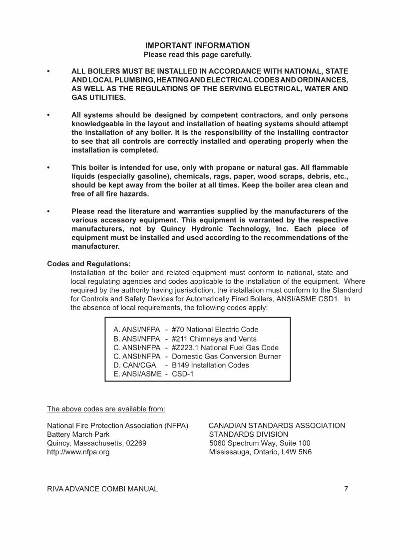
Codes and Regulations:Installation of the boiler and related equipment must conform to national, state and local regulating agencies and codes applicable to the installation of the equipment. Where required by the authority having jusrisdiction, the installation must conform to the Standard for Controls and Safety Devices for Automatically Fired Boilers, ANSI/ASME CSD1. In the absence of local requirements, the following codes apply:
A. ANSI/NFPA
-
#70 National Electric Code B. ANSI/NFPA - #211 Chimneys and Vents C. ANSI/NFPA - #Z223.1 National Fuel Gas Code C. ANSI/NFPA - Domestic Gas Conversion Burner D. CAN/CGA - B149 Installation Codes E. ANSI/ASME - CSD-1
The above codes are available from:
National Fire Protection Association (NFPA) CANADIAN STANDARDS ASSOCIATIONBattery March Park STANDARDS DIVISIONQuincy, Massachusetts, 02269 5060 Spectrum Way, Suite 100http://www.nfpa.org Mississauga, Ontario, L4W 5N6
8 RIVA ADVANCE COMBI MANUAL
1. General Information
2. Technical Information (M210.32 CM)
The Riva Advance Combi is a high efficiency condensing, wall mounted gas boiler which provides central heat. The boiler features a gas valve which modulates the energy input from 32,000 BTU/h to 125,000 BTU/h. The boiler is shipped fully assembled with the components listed on pages 10-11. All units are pressure and combustion tested at the factory prior to shipping.
Key Features:
• Wall mountable - saving valuable floor space.
• Several flue options available• Electronic spark ignition• Safety flow switch - positioned on the
main circuit, which monitors the flow and protects the main heat exchanger from thermal shock should there be a lack of water in the system.
• Frost protection - contains an integral frost protection system to prevent frost damage which can occur in areas susceptible to very cold weather conditions.
• Boiler operation recognition system - should the boiler not be used for longer than 24 hours, it then performs a controlled system test to ensuring the motorized components within the boiler do not become inoperable due to lack of use.
• Gas valve modulation - the gas input modulates based off central heating temperature to within ± 2 ºF.
• Diagnostic information system equipped with three LED diagnostic lights for quick error assessment.
GENERALHeight in 31.6
Width in 15.7
Depth in 13.8
Weight lb 109.5
ELECTRICALVoltage V 120
Frequency Hz 60
Current A 1.6
Power consumption W 180
RESTRICTORS REFERENCES
Gas(ø mm)
Air(color)
Natural N/A BLUE
Propane 548 BLUE
CENTRAL HEATINGMaximum working temp. °F 185
Temp. Regulation range* °F 100-185
Maximum pressure psi 30.0
Minimum pressure psi 4.35
Max head loss (at 4.4 GPM) ft 8.25
*At the minimum useful output
RIVA ADVANCE COMBI MANUAL 9
2. Technical Information Cont.
ENERGY CAPACITYNominal heat input(0/2000 ft) MBH 125.0
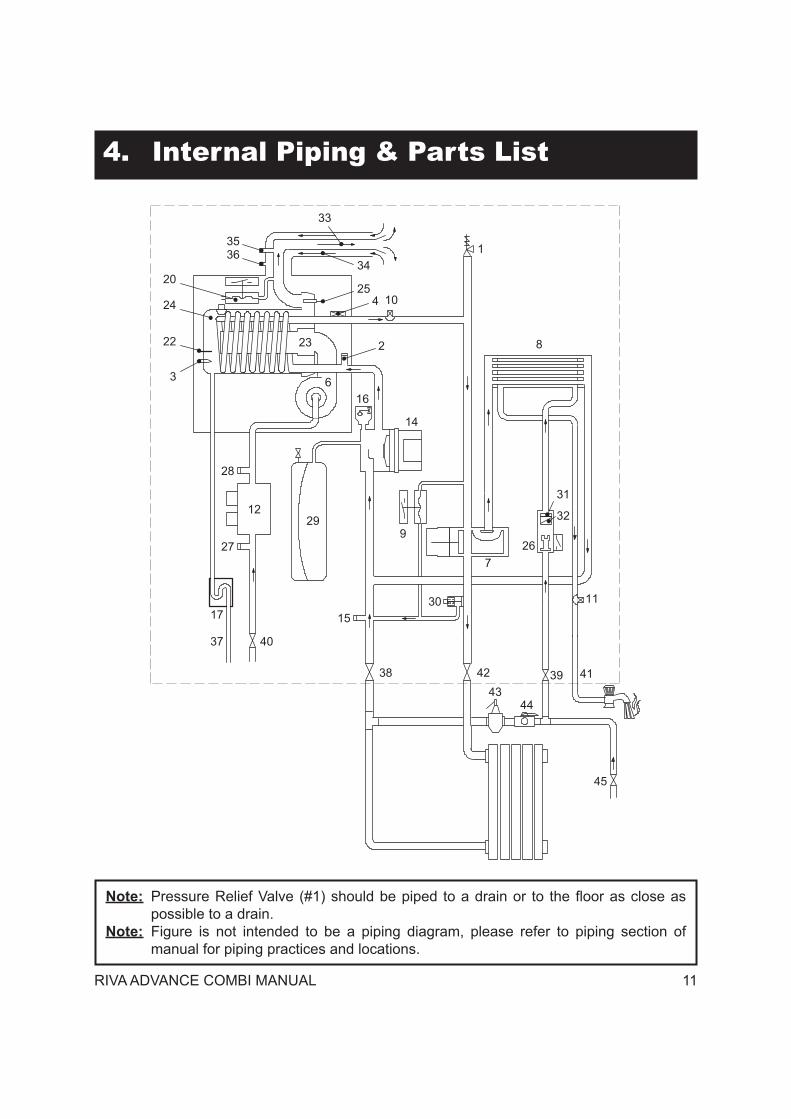
14 Pump15 Main circuit drain valve16 Automatic air purger valve17 Condensate trap18 Air hose19 Transformer20 Air box (air/gas mixer)21 Air pressure switch22 Flame-detecting electrode23 Burner24 Condensing heat exchanger25 Flue temperature probe NTC26 D.h.w. flow switch27 Gas valve inlet pressure test point28 Gas valve outlet pressure test point29 C.h. expansion tank30 By-pass valve31 Domestic water circuit filter32 D.h.w. flow limiter33 Flue outlet pipe34 Air intake pipe35 Flue exhaust sampling point36 Air sampling point37 Condensate drain pipe38 C.h. return valve39 Domestic cold water inlet valve40 Gas inlet valve41 D.h.w. outlet pipe42 C.h. flow valve43 Pressure reducing automatic fill valve
(Not Supplied)44 Backflow preventer (Not Supplied)45 Water supply inlet cock
RIVA ADVANCE COMBI MANUAL 11
4. Internal Piping & Parts List
8
1
31
4
2
25
34
3
22
24
20
3536
33
267
11
41394243
44
45
38
4037
17 1530
9
10
14
2912
27
28
166
23
32
Note: Pressure Relief Valve (#1) should be piped to a drain or to the floor as close as possible to a drain.
Note: Figure is not intended to be a piping diagram, please refer to piping section of manual for piping practices and locations.
12 RIVA ADVANCE COMBI MANUAL
5. Electric Diagrams
Caution:Label all wires prior to disconnection when servicing controls. Wiring errors can cause improper and dangerous operation.Verify proper operation after servicing.
LD1LD2LD3
F1F2
K1
K2
K3
K4
LD4P6
T3
X1
X2
X3
X5
X6
X7 X10X11X12
X13
X17
X23
X24
P3
X14
X15
SB1
X16
X22
X9
BL BR
WGY
BLWGYBR
123
L N
Y/G BLBR
RBL
BR BL
Y/G
BK BL
GYY/G BL
M~
RBL
BK
3
2
1
Y/G
BL GY R BK BL BL BK
Y/G
BKBLBK
13
4
Y/G
BL BR
BR BL
WO W
GY
t
t
BKR
R
BK
BL
BL
BL B
L
R
W
BL
WBL
R
M~
R BK
GY W
RGY
WBK
t
BR
BL
WB
K
BKW
BRBL
COM
NO
R
R
RR
GY
BK
GY
External controlsterminal block
Electric supplyterminal block
Pump
Three-waydiverter valve
Gas valveCH temperature
probe NTC
DHW temp.probe NTC
DHW flowswitch
SafetythermostatFlue probe
Primarycircuit flow
switchFanIgnition
electrodesFlamedetectionelectrode
Transformer120V~/24V~
SparkG
enerator
R BK
R BK W GY
W
GY
Remote Externaltemp. probe
terminal block
R
R
W W
Display LCD
GY
BK
Air pressureswitch
COM
NC NO
1 6
8
11
1
2
3
W
GY
BL Blue GY Gray Y/G Yellow/GreenBK Black O Orange W WhiteBR Brown R Red
RIVA ADVANCE COMBI MANUAL 13
5. Electric Diagrams Cont.5.1 Sequence of Operation:
Is boiler locked out?
NO
Switch in the function mode
Takingwater from the domestic hot
water circuit?YES circulator off
fan stillcirculator on
Is primary circuittemperature higher than that
selected?
YES
Main circuit pressureswitch consense? NOYES
NO
NO
starts fanchecks fan rpm
YES
cancels lock
Is fan rpmexact?
NO YESIs flue
temperature higher than 110°C?
YES
NO
beginning of wait period
End of waitperiod?YES NO
YES
starts ignition dischargesOpens gas valve
beginning of ignition periodflame presence? YES
interrupts ignition dischargesgas valve open
fan runs
End of ignitionperiod?
NO
NO YES
closes gas valvestops fan
interrupts ignition discharges
turns on lock---out lightindicates lock
reset push---buttonpressed?
flame presence? NO
NOIs fan rpmexact? YES
NO
safety thermostat or fluetemperature probe lock out? YESNO
YES
YES
YES
flame presence?
LCD
E04 +
LCD
E05 +
LCD
E09 +
NO
Thermal control in the mode
14 RIVA ADVANCE COMBI MANUAL
5. Electric Diagrams Cont.
lock memorised?
NO
Switch in the function mode
Takingwater from the domestic hot
water circuit?Request for heat from
room thermostat?
See functioning with the functioncontrol in the mode
(sec. 9.11)
YES
circulator offfan still
NO
circulator on
Is primary circuittemperature higher than that
selected?
YES
Main circuit pressureswitch consense? NOYES
NO
NO
starts fanchecks fan rpm
YES
cancels lock
Is fan rpmexact?
NO YESIs flue
temperature higher than 110°C?
YES
NO
beginning of wait period
End of waitperiod?YES NO
starts ignition dischargesOpens gas valve
beginning of ignition periodflame presence? YES
interrupts ignition dischargesgas valve open
fan runs
End of ignitionperiod?
NO
NO YEScloses gas valve
stops faninterrupts ignition discharges
memorizes lockturns on lock---out light
reset push---buttonpressed?
flame presence? NO
NOIs fan rpmexact? YES
NO
safety thermostat or fluetemperature probe lock out? YESNO
YES
YES
YES
YESflame presence?
LCD
E04 +
LCD
E09 +
LCD
E05 +
Thermal control in the mode
RIVA ADVANCE COMBI MANUAL 15
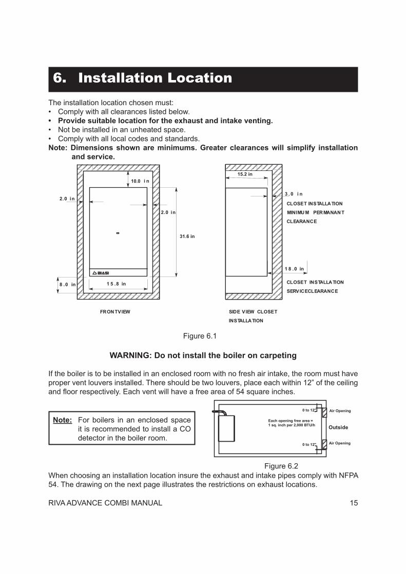
6. Installation LocationThe installation location chosen must:• Comply with all clearances listed below.• Provide suitable location for the exhaust and intake venting.• Not be installed in an unheated space.• Comply with all local codes and standards.Note: Dimensions shown are minimums. Greater clearances will simplify installation
and service.
Figure 6.1
WARNING: Do not install the boiler on carpeting
If the boiler is to be installed in an enclosed room with no fresh air intake, the room must have proper vent louvers installed. There should be two louvers, place each within 12” of the ceiling and floor respectively. Each vent will have a free area of 54 square inches.
3 . 0 i n2.0 in
10.0 i n
2.0 in
CLOSET INSTALLATION
MINIMU M PER MANAN T
CLEARANCE
FRON TVIEW SIDE VIEW CLOSET
INSTALLATION
CLOSET INSTALLATION
SERVICECLEARANCE
1 8 .0 in
31.6 in
8 .0 in 1 5 .8 in
15.2 in
Figure 6.2
Outside
Air Opening
Air Opening
Each opening free area =1 sq. inch per 2,000 BTU/h
0 to 12"
0 to 12"
When choosing an installation location insure the exhaust and intake pipes comply with NFPA 54. The drawing on the next page illustrates the restrictions on exhaust locations.
Note: For boilers in an enclosed space it is recommended to install a CO detector in the boiler room.
16 RIVA ADVANCE COMBI MANUAL
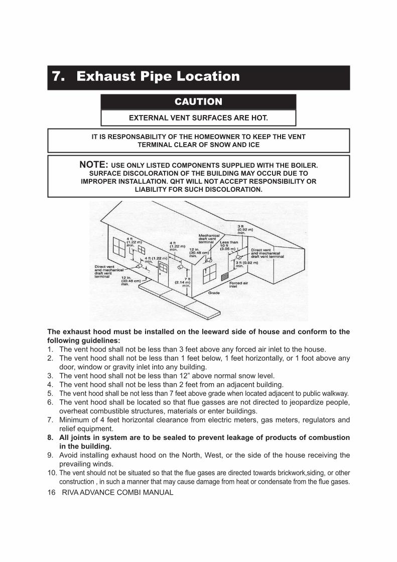
7. Exhaust Pipe Location
CAUTIONEXTERNAL VENT SURFACES ARE HOT.
IT IS RESPONSABILITY OF THE HOMEOWNER TO KEEP THE VENTTERMINAL CLEAR OF SNOW AND ICE
NOTE: USE ONLY LISTED COMPONENTS SUPPLIED WITH THE BOILER.SURFACE DISCOLORATION OF THE BUILDING MAY OCCUR DUE TO
IMPROPER INSTALLATION. QHT WILL NOT ACCEPT RESPONSIBILITY ORLIABILITY FOR SUCH DISCOLORATION.
The exhaust hood must be installed on the leeward side of house and conform to the following guidelines:1. The vent hood shall not be less than 3 feet above any forced air inlet to the house. 2. The vent hood shall not be less than 1 feet below, 1 feet horizontally, or 1 foot above any
door, window or gravity inlet into any building.3. The vent hood shall not be less than 12” above normal snow level.4. The vent hood shall not be less than 2 feet from an adjacent building.5. The vent hood shall be not less than 7 feet above grade when located adjacent to public walkway.6. The vent hood shall be located so that flue gasses are not directed to jeopardize people,
overheat combustible structures, materials or enter buildings.7. Minimum of 4 feet horizontal clearance from electric meters, gas meters, regulators and
relief equipment.8. All joints in system are to be sealed to prevent leakage of products of combustion
in the building.9. Avoid installing exhaust hood on the North, West, or the side of the house receiving the
prevailing winds.10. The vent should not be situated so that the flue gases are directed towards brickwork,siding, or other
construction , in such a manner that may cause damage from heat or condensate from the flue gases.
RIVA ADVANCE COMBI MANUAL 17
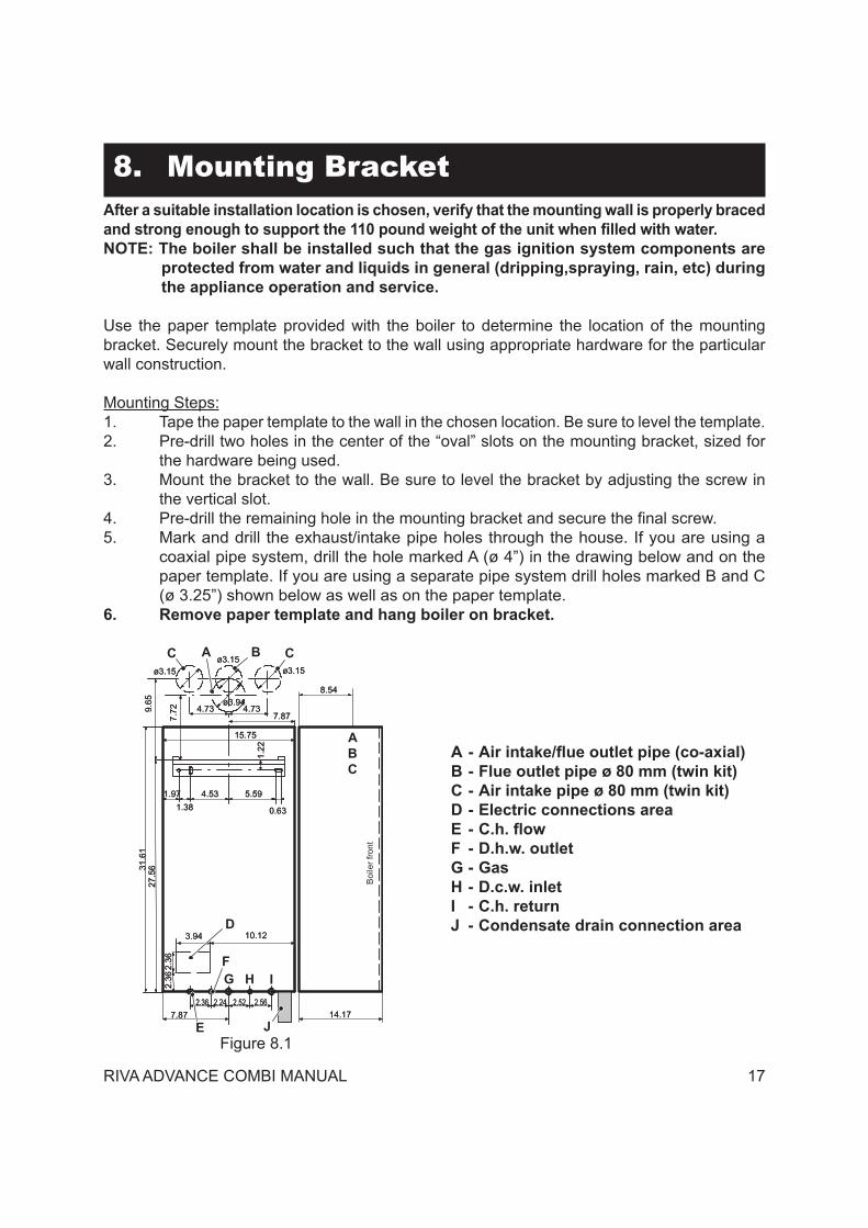
8. Mounting BracketAfter a suitable installation location is chosen, verify that the mounting wall is properly braced and strong enough to support the 110 pound weight of the unit when filled with water. NOTE: The boiler shall be installed such that the gas ignition system components are
protected from water and liquids in general (dripping,spraying, rain, etc) during the appliance operation and service.
Use the paper template provided with the boiler to determine the location of the mounting bracket. Securely mount the bracket to the wall using appropriate hardware for the particular wall construction.
Mounting Steps:1. Tape the paper template to the wall in the chosen location. Be sure to level the template.2. Pre-drill two holes in the center of the “oval” slots on the mounting bracket, sized for
the hardware being used.3. Mount the bracket to the wall. Be sure to level the bracket by adjusting the screw in
the vertical slot.4. Pre-drill the remaining hole in the mounting bracket and secure the final screw.5. Mark and drill the exhaust/intake pipe holes through the house. If you are using a
coaxial pipe system, drill the hole marked A (ø 4”) in the drawing below and on the paper template. If you are using a separate pipe system drill holes marked B and C (ø 3.25”) shown below as well as on the paper template.
6. Remove paper template and hang boiler on bracket.
Figure 8.1
Boi
lerf
ront
ø3.15 ø3.15
ø3.94
15.75
7.87
9.65
7.72
31.6
127
.56
1.384.53 5.59
0.63
1.22
2.36
2.36
3.94 10.12
7.872.562.522.242.36
1.97
4.73
14.17
8.54
4.73
ø3.15ø3.15 ø3.15
ø3.94
15.75
7.87
9.65
7.72
31.6
127
.56
1.384.53 5.59
0.63
1.22
2.36
2.36
3.94 10.12
7.872.562.522.242.36
1.97
4.73
14.17
8.54
4.73
ø3.15A
A
B
B
C C
C
D
J E
F G H I
A - Air intake/flue outlet pipe (co-axial)B - Flue outlet pipe ø 80 mm (twin kit)C - Air intake pipe ø 80 mm (twin kit)D - Electric connections areaE - C.h. flowF - D.h.w. outletG - GasH - D.c.w. inletI - C.h. returnJ - Condensate drain connection area
18 RIVA ADVANCE COMBI MANUAL
9. VentingThe Riva Advance Combi is a mechanical draft, side wall vented boiler. There are two side wall flue options available – separate and coaxial. The coaxial option has one configuration shown on the next page. The separate option has two possible configurations shown on the following pages. There is also a vertical roof venting option. Regardless of what vent kit is installed, they should all conform to the Provisions for combustion and ventilation air in accordance with section 5.3, Air for Combustion and Ventilation, of the National Fuel Gas Code, ANSI Z223.1, or Sections 7.2, 7.3 or 7.4 of CAN/CGA B149, Installation Codes, or applicable provisions of the local building codes.
If the Biasi Riva Advance Combi replaces a boiler that was attached to a common vent system, the common venting system is likely to be too large for proper venting of the appliances remaining connected to it. To ensure the remaining appliances will function properly, the test procedure below should be followed:
At the time of removal of an existing boiler, the following steps shall be followed with each appliance remaining connected to the common venting system placed in operation, while the other appliances remaining connected to the common venting system are not in operation.(a) Seal any unused openings in the common venting system.(b) Visually inspect the venting system for proper size and horizontal pitch and determine
there is no blockage or restriction, leakage, corrosion and other deficiencies which could cause an unsafe condition.
(c) Insofar as is practical, close all building doors and windows and all doors between the space in which the appliances remaining connected to the common venting system are located and other spaces of the building. Turn on clothes dryers and any appliance not connected to the common venting system. Turn on any exhaust fans, such as range hoods and bathroom exhausts, so they will operate at maximum speed. Do not operate a summer exhaust fan. Close fireplace dampers.
(d) Place in operation the appliance being inspected. Follow the lighting instructions. Adjust thermostat so appliance will operate continuously.
(e) Test for spillage at the draft hood relief opening after 5 minutes of main burner operation. Use the flame of a match or candle, or smoke from a cigarette, cigar or pipe.
(f) After it has been determined that each appliance remaining connected to the common venting system properly vents when tested as outlined above, return doors, windows, exhaust fans, fireplace dampers and any other gas-burning appliance to their previous condition of use.” (g) Any improper operation of the common venting system should be corrected so the installation conforms with the National Fuel Gas Code, ANSI Z223.1 and/or CAN/CGA B149, Installation Codes. When resizing any portion of the common venting system, the common venting system should be resized to approach the minimum size as determined using the appropriate tables in Part 11 of the National Fuel Gas Code, ANSI Z223.1 and/or CAN/CGA B149, Installation Codes.
RIVA ADVANCE COMBI MANUAL 19
The Commonwealth of Massachusetts requires compliance with regulation 248 CMR 4.00 and 5.00 for installation of through – the – wall vented gas appliances as follows:(a) For direct-vent appliances, mechanical-vent heating appliances or domestic hot water equipment, where the bottom of the vent terminal and the air intake is installed below four feet above grade the following requirements must be satisfied:
1. If there is not one already present, on each floor level where there are bedroom(s), a carbon monoxide detector and alarm shall be placed in the living area outside the bedroom(s). The carbon monoxide detector shall comply with NFPA 720 (2005 Edition).
2. A carbon monoxide detector shall be located in the room that houses the appliance or equipment and shall:
a. Be powered by the same electrical circuit as the appliance or equipment such that only one service switch services both the appliance and the carbon monoxide detector;
b. Have battery back-up power;c. Meet ANSI/UL 2034 Standards and comply with NFPA 720 (2005 Edition);andd. Have been approved and listed by a Nationally Recognized Testing Laboratory
as recognized under 527 CMR.3. A Product-approved vent terminal must be used, and if applicable, a Product-approved air intake must be used. Installation shall be in strict compliance with the manufacturer’s instructions. A copy of the installation instructions shall remain with the appliance or equipment at the completion of the installation.
4. A metal or plastic identification plate shall be mounted at the exterior of the building, four feet directly above the location of vent terminal. The plate shall be of sufficient size to be easily read from a distance of eight feet away, and read “Gas Vent Directly Below”.(b) For direct-vent appliances, mechanical-vent heating appliances or domestic hot water equipment where the bottom of the vent terminal and the air intake is installed above four feet above grade the following requirements must be satisfied:
1. If there is not one already present, on each floor level where there are bedroom(s), a carbon monoxide detector and alarm shall be placed in the living area outside the bedroom(s). The carbon monoxide detector shall comply with NFPA 720 (2005 Edition).
2. A carbon monoxide detector shall:a. Be located in the room that houses the appliance or equipment;b. Be either hard-wired or battery powered or both; andc. Shall comply with NFPA 720 (2005 Edition).
3. A Product-approved vent terminal must be used, and if applicable, a Product-approved air intake must be used. Installation shall be in strict compliance with the manufacturer’s instructions. A copy of the installation instructions shall remain with the appliance or equipment at the completion of the installation.
9. Venting Requirements for the State of Massachusetts
20 RIVA ADVANCE COMBI MANUAL
9. Venting Cont.9.1 Fitting the flue system:
In general, it has to be taken in consideration that the horizontal sections of the flue pipe must have an horizontal sloping not less than 1.5 degree (0.3 in per ft) towards the boiler.In the standard horizontal flue kit the flue pipe is angled within the air duct therefore the air duct must be horizontally installed.If one or more extensions have to be used they must be adequately supported so that there is no sag in the flue pipe and a minimum fall of 1.5 degree (0.3 in per ft) over the whole length towards the boiler is ensured.
9.2 Choice of flue:
The following flue kits are available for connecting to the boiler:
A Standard coaxial horizontal flue kit (Exhaust & intake outside) - PART# RI-9990387
It can be mounted to allow discharge to the rear or either side of the boiler via the flanged boiler adapter elbow. Minimum length required is 1.5 ft. Maximum equivalent length of 33 ft can be achieved utilizing extensions. This flue system can only be used to discharge horizontally, it is not designed to enable termination in the vertically.
Installation:• Drill a hole 4.5” in diameter through the outside wall that is less than 18” thick.• Cut the pipe as necessary so that a no more than 6” protrudes from the house.• Slide the intake and exhaust pipes through the hole.• Slide one rubber wall trim piece on the pipe from inside and one from outside.• Connect exhaust (inner) pipe to concentric elbow.• Connect intake (outer) pipe to concentric elbow.• Secure elbow to boiler using gasket and four screws provided.• Secure end cap on the intake pipe outside the house.
RIVA ADVANCE COMBI MANUAL 22
9. Venting Cont.
F Plastic vent requirements
All piping that is used to vent the Riva Advance Combi boiler must conform to the standards listed below.
It is not permitted to use a cellular core PVC (ASTM F891), cellular core CPVC, or Radel®
Parts Material United States Canada
Exhaust and Intake Piping
PVC ANSI/ASTM D1785
ULC S636CPVC ANSI/ASTM DF441
Pipe Cement /Primer
PVC ANSI/ASTM D2564CPVC ANSI/ASTM F493
(polyphenolsulfone) in venting systems. Covering non-metallic vent thermal insulation shall be prohibited.
Polypropylene
CPVC or Polypropylene pipe. After that point it is permissible to assemble the rest of the vent in PVC. It is recommended to finish the piping using CPVC or Polypropylene.
Canadian Installations:•
as a system and must be installed as such. Different manufacturers have different materials,
different BH Vent manufacturers, this can result in unsafe conditions.• Consult PVC/CPVC manufacturer’s installation manual for correct joining of pipe for gas
venting.
General installation PVC/CPVC:1. 2. Disassemble the system and de burr the inside and outside of the pipe ends.3. Chamfer the outside of each end of the pipes.4.
surfaces.5. 6. 7. 8. Rotate the pipe 1/4 turn and hold in place for 30 seconds.9. Wipe any excess cement away and check that there is a complete bead of sealant around
10. Allow to cure for 2 hours before commissioning the boiler. 11. Install perforated metal pipe supports onto the pipe, making sure there is no sagging in the
pipe. Place supports as close as possible to elbows to relieve stress on the joint.
23 RIVA ADVANCE COMBI MANUAL
9. Venting Cont.
G PVC boiler adapter - Part# RI-99909120
Figure 9.6
This kit is required to vent the Riva Advance Combi boiler using PVC/CPVC pipe. The kit includes a boiler connection adapted for PVC/CPVC. When venting with PVC/CPVC this boiler adapter is required in addition to one of the terminations on the following pages.
Canada: All PVC/CPVC pipe, fittings, and cement must be approved to ULC S636. Do not mix pipe and joining compounds from different manufacturers as this can result in an unsafe condition and void the certification.
Installation:• Attach the collar (C) from the adapter kit to the top of the boiler using the supplied screws.• Insert the boiler adapter (B) into the collar. Check that the exhaust gasket (D) is installed on
the outlet of the boiler first.• Once the adapter is positioned in place, tighten the clamp on the collar and install the
supplied self tapping screw through the pre drilled hole on the collar. • Insert the PVC adapters (A) into the boiler adapter (B).• Slide the CPVC/PVC pipe into the PVC adapters (A), do not use any solvents or cement
on this connection. It is a gasket connection that requires no sealing. If polypropylene pipe is being used, remove the PVC adapter A from the boiler adapter. Insert the polypropylene pipe into the boiler adapter and use the PVC adapter in the end of the polypropylene pipe to convert to PVC.
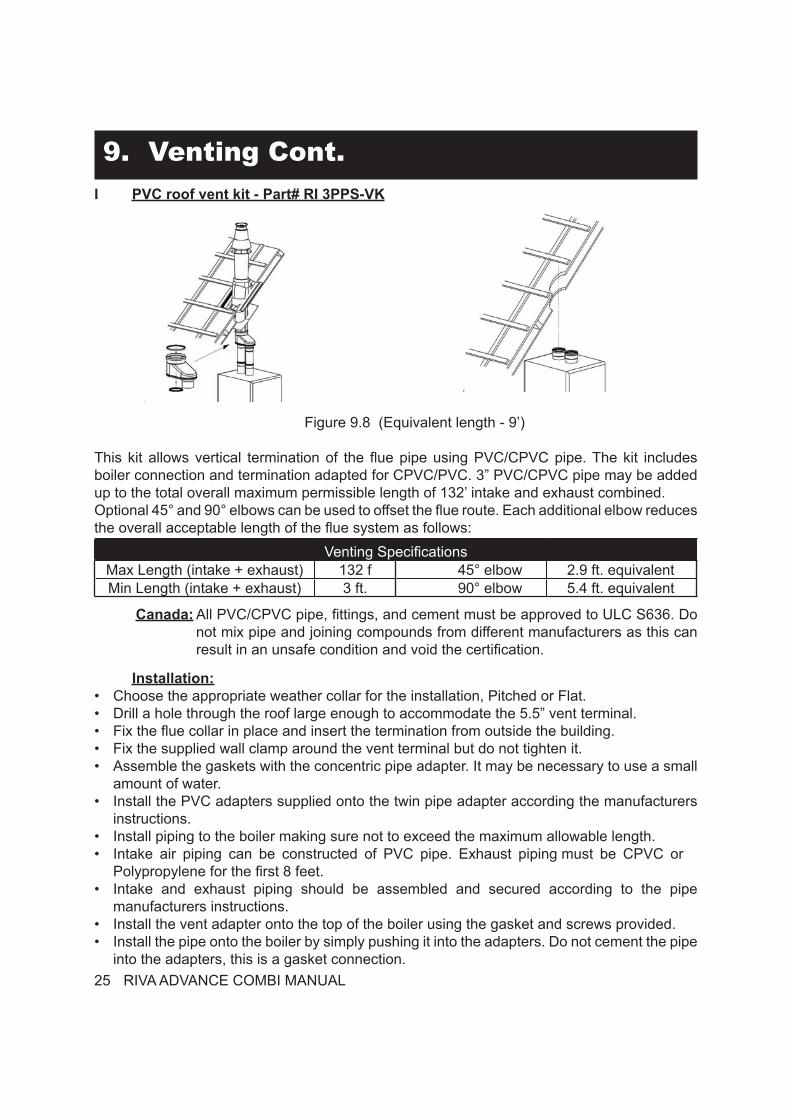
This kit allows horizontal termination of the flue pipe using PVC/CPVC pipe. The kit includes boiler connection and termination adapted for CPVC/PVC. 3” PVC/CPVC pipe may be added up to the total overall maximum permissible length of 132’ intake and exhaust combined. Optional 45° and 90° elbows can be used to offset the flue route. Each additional elbow reduces the overall acceptable length of the flue system as follows:
Venting SpecificationsMax Length (intake + exhaust) 132 f 45° elbow 2.9 ft. equivalentMin Length (intake + exhaust) 3 ft. 90° elbow 5.4 ft. equivalent
Canada: All PVC/CPVC pipe, fittings, and cement must be approved to ULC S636. Do
not mix pipe and joining compounds from different manufacturers as this can result in an unsafe condition and void the certification.
Installation:• Drill 5.5” hole through the outside wall making sure there is 1 foot clearance above normal
snow level.• Insert the termination through the flexible exterior gasket and the building wall.• Fix the exterior gasket to the wall using 4 contractor supplied fasteners.• Slide the interior wall gasket over the termination and fix it to the wall using 4 user supplied
fasteners.• Assemble the gaskets into the twin pipe adapter.• Install the twin pipe adapter onto the termination.• Install the PVC adapters supplied onto the twin pipe adapter according the manufacturers
instructions.• Install piping pitched back toward the boiler making sure not to exceed the maximum
allowable length.• Intake air piping can be constructed of PVC pipe. Exhaust piping must be CPVC or
Polypropylene for the first 8 feet.• Intake and exhaust piping should be assembled and secured according to the pipe
manufacturers instructions.• Install the vent adapter onto the top of the boiler using the gasket and screws provided.• Install the pipe onto the boiler by simply pushing it into the adapters. Do not cement the pipe
This kit allows vertical termination of the flue pipe using PVC/CPVC pipe. The kit includes boiler connection and termination adapted for CPVC/PVC. 3” PVC/CPVC pipe may be added up to the total overall maximum permissible length of 132’ intake and exhaust combined.Optional 45° and 90° elbows can be used to offset the flue route. Each additional elbow reduces the overall acceptable length of the flue system as follows:
Venting SpecificationsMax Length (intake + exhaust) 132 f 45° elbow 2.9 ft. equivalentMin Length (intake + exhaust) 3 ft. 90° elbow 5.4 ft. equivalent
Canada: All PVC/CPVC pipe, fittings, and cement must be approved to ULC S636. Do not mix pipe and joining compounds from different manufacturers as this can result in an unsafe condition and void the certification.
Installation:• Choose the appropriate weather collar for the installation, Pitched or Flat.• Drill a hole through the roof large enough to accommodate the 5.5” vent terminal.• Fix the flue collar in place and insert the termination from outside the building.• Fix the supplied wall clamp around the vent terminal but do not tighten it.• Assemble the gaskets with the concentric pipe adapter. It may be necessary to use a small
amount of water.• Install the PVC adapters supplied onto the twin pipe adapter according the manufacturers
instructions.• Install piping to the boiler making sure not to exceed the maximum allowable length.• Intake air piping can be constructed of PVC pipe. Exhaust piping must be CPVC or
Polypropylene for the first 8 feet.• Intake and exhaust piping should be assembled and secured according to the pipe
manufacturers instructions.• Install the vent adapter onto the top of the boiler using the gasket and screws provided.• Install the pipe onto the boiler by simply pushing it into the adapters. Do not cement the pipe
This kit allows for venting of the boiler through an existing chimney way. The kit includes all the parts needed from the chimney thimble to the chimney top termination. It is not permited to use any other vent system than the listed kit. The connection to the boiler should be constructed of polypropylene pipe lengths. The total overall maximum permissible length of 50’ liner and chimney connector combined. Optional 45° and 90° elbows can be used to offset the flue route.
Installation:• Please refer to the manufacturers
instructions for installation of the liner kit.• Once liner has been installed install piping
to the boiler using 3” polypropylene pipe making sure not to exceed the maximum allowable length.
• Intake air piping can be constructed of Polypropelyene pipe. Exhaust piping can only be constructed of a high temperature pipe like polypropylene.
• Intake and exhaust piping should be assembled and secured according to the pipe manufacturers instructions.
• Install the vent adapter onto the top of the boiler using the gasket and screws provided and remove the PVC adapters supplied with the adapter.
• Install the pipe onto the boiler by simply pushing it into the adapters. Do not cement the pipe into the adapters, this is a gasket connection.
Figure 9.9 1
6
13
12
11
10
7
9
8
7
5
4
3
2
1. Single wall shaft connector2. Support elbow3. Support bracket4. Male flex adapter to rigid5. Clamp (or tie)6. Coupling7. Seal8. Flex liner9. Spacer bracket10. Support cross11. Female flex adapter to rigid12. Weather collar13. Metal termination pipe
27 RIVA ADVANCE COMBI MANUAL
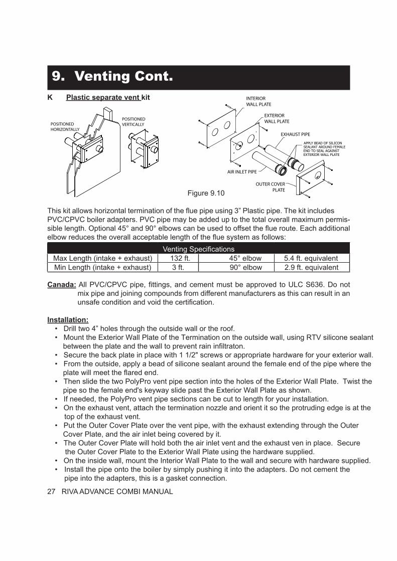
9. Venting Cont.K Plastic separate vent kit
Figure 9.10
This kit allows horizontal termination of the flue pipe using 3” Plastic pipe. The kit includes PVC/CPVC boiler adapters. PVC pipe may be added up to the total overall maximum permis-sible length. Optional 45° and 90° elbows can be used to offset the flue route. Each additional elbow reduces the overall acceptable length of the flue system as follows:
Venting SpecificationsMax Length (intake + exhaust) 132 ft. 45° elbow 5.4 ft. equivalentMin Length (intake + exhaust) 3 ft. 90° elbow 2.9 ft. equivalent
Canada: All PVC/CPVC pipe, fittings, and cement must be approved to ULC S636. Do not mix pipe and joining compounds from different manufacturers as this can result in an unsafe condition and void the certification.
Installation:• Drill two 4” holes through the outside wall or the roof. • Mount the Exterior Wall Plate of the Termination on the outside wall, using RTV silicone sealant between the plate and the wall to prevent rain infiltraton.• Secure the back plate in place with 1 1/2" screws or appropriate hardware for your exterior wall.• From the outside, apply a bead of silicone sealant around the female end of the pipe where the plate will meet the flared end.• Then slide the two PolyPro vent pipe section into the holes of the Exterior Wall Plate. Twist the pipe so the female end's keyway slide past the Exterior Wall Plate as shown.• If needed, the PolyPro vent pipe sections can be cut to length for your installation.• On the exhaust vent, attach the termination nozzle and orient it so the protruding edge is at the
top of the exhaust vent.• Put the Outer Cover Plate over the vent pipe, with the exhaust extending through the Outer Cover Plate, and the air inlet being covered by it.• The Outer Cover Plate will hold both the air inlet vent and the exhaust ven in place. Secure the Outer Cover Plate to the Exterior Wall Plate using the hardware supplied.• On the inside wall, mount the Interior Wall Plate to the wall and secure with hardware supplied.• Install the pipe onto the boiler by simply pushing it into the adapters. Do not cement the
pipe into the adapters, this is a gasket connection.
POSITIONEDHORIZONTALLY
POSITIONEDVERTICALLY
INTERIORWALL PLATE
EXTERIOR WALL PLATE
EXHAUST PIPE
AIR INLET PIPE
OUTER COVER PLATE
APPLY BEAD OF SILICONSEALANT AROUND FEMALE END TO SEAL AGAINST EXTERIOR WALL PLATE
RIVA ADVANCE COMBI MANUAL 28
10. Pipe ConnectionsThe Riva Advance Combi is supplied with a 3/4” stainless steel gas pipe (A in figure 10.1), 2 - 3/4” copper pipe (C, D in figure 10.1), 2 - 1/2” (F, G in figure 10.1) located in a plastic bag in the boiler package.
Figure 10.1 AEC F D
G
B
A) Stainless steel gas pipeB) Main circuit drain cockC) C.h. supply copper pipeD) C.h. return copper pipeE) D.h.w. outlet pipeF) D.h.w. inlet pipeG) Condensate trap
Installation:• Remove the protective caps off boiler connections (Figure 10.1).• Thoroughly clean the connections.• Attach the supplied components to the boiler connections (see Figures 10.1). Be sure to
use the proper gaskets for the pipe connections.• Attach the PRV to the PRV discharge pipe on the top of the boiler. Be sure to use the 3/4”
flat washer supplied for the connection.• Attach the condensate trap to an appropriate drain pipe.• Before connecting the boiler to the heating system piping, review the suggested piping
diagrams in Section 4 (page 11).• If the c.h. system is above the boiler level, it is advisable to install c.h. cocks close to the
boiler for service.• A hot water boiler installed above radiation level or as required by the Authority having
jurisdiction, must be provided with a low water cutoff device elther as part of the boiler or at the time of boiler installation.
Condensate trap:
The condensate trap allows the discharge of the condensate via the condensate drain pipe while preventing the escape of combustion products. A plastic ball closes the trap outlet in case that the trap is empty. The condensate trap is provided with two electrodes: if the drain pipe is plugged or in any case in which the condensate isn’t correctly evacuated, the condensate level in the trap rises putting in contact the electrodes thus causing the boiler lock-out.
29 RIVA ADVANCE COMBI MANUAL
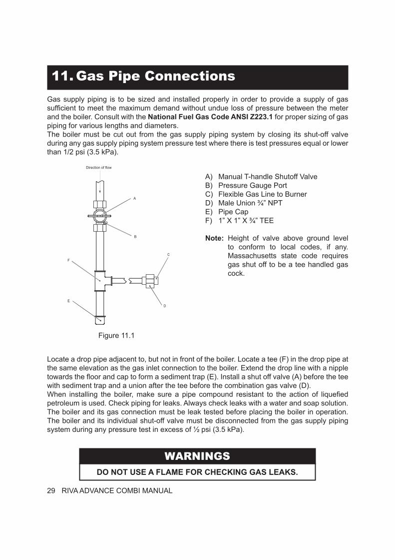
11. Gas Pipe ConnectionsGas supply piping is to be sized and installed properly in order to provide a supply of gas sufficient to meet the maximum demand without undue loss of pressure between the meter and the boiler. Consult with the National Fuel Gas Code ANSI Z223.1 for proper sizing of gas piping for various lengths and diameters.The boiler must be cut out from the gas supply piping system by closing its shut-off valve during any gas supply piping system pressure test where there is test pressures equal or lower than 1/2 psi (3.5 kPa).
Figure 11.1
Direction of flow
B
A
F
ED
C
A) Manual T-handle Shutoff ValveB) Pressure Gauge PortC) Flexible Gas Line to BurnerD) Male Union ¾” NPTE) Pipe CapF) 1” X 1” X ¾” TEE
Note: Height of valve above ground level to conform to local codes, if any. Massachusetts state code requires gas shut off to be a tee handled gas cock.
Locate a drop pipe adjacent to, but not in front of the boiler. Locate a tee (F) in the drop pipe at the same elevation as the gas inlet connection to the boiler. Extend the drop line with a nipple towards the floor and cap to form a sediment trap (E). Install a shut off valve (A) before the tee with sediment trap and a union after the tee before the combination gas valve (D).When installing the boiler, make sure a pipe compound resistant to the action of liquefied petroleum is used. Check piping for leaks. Always check leaks with a water and soap solution.The boiler and its gas connection must be leak tested before placing the boiler in operation. The boiler and its individual shut-off valve must be disconnected from the gas supply piping system during any pressure test in excess of ½ psi (3.5 kPa).
WARNINGSDO NOT USE A FLAME FOR CHECKING GAS LEAKS.
RIVA ADVANCE COMBI MANUAL 30
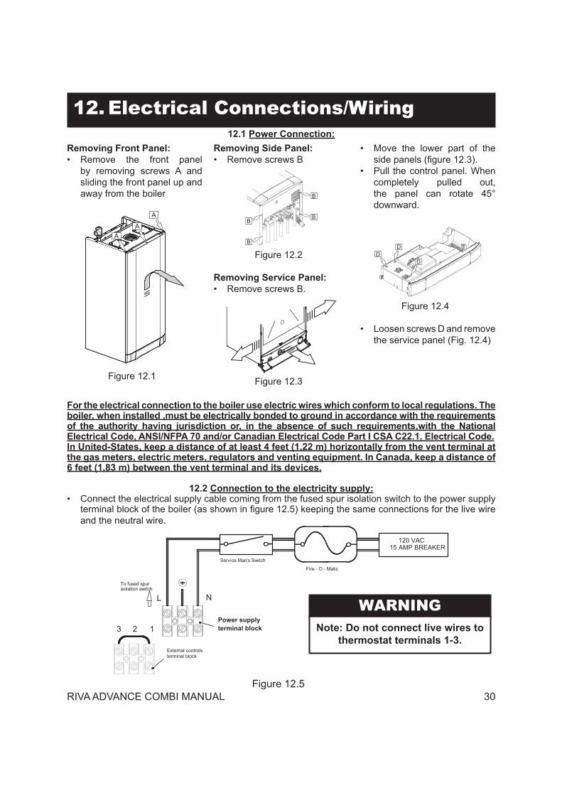
12. Electrical Connections/Wiring
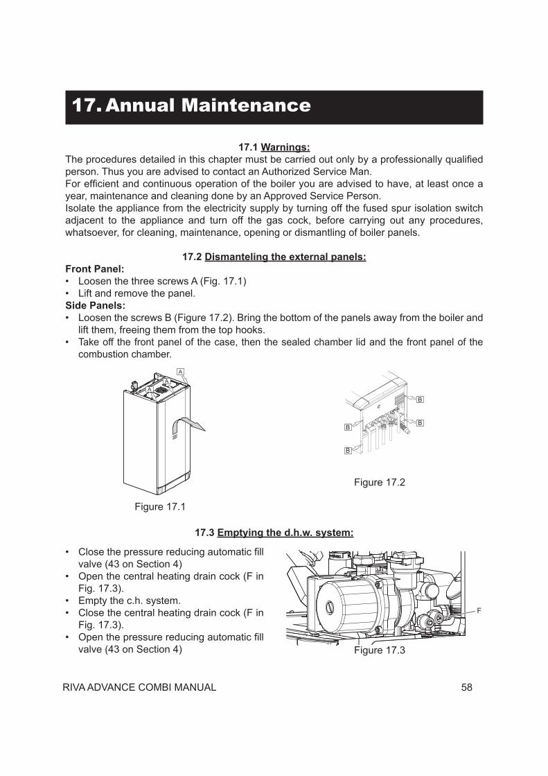
Removing Front Panel:• Remove the front panel
by removing screws A and sliding the front panel up and away from the boiler
Figure 12.1
A
A
A
Removing Side Panel:• Remove screws B
Figure 12.2
B
BB
B
Removing Service Panel:• Remove screws B.
Figure 12.3
• Move the lower part of the side panels (figure 12.3).
• Pull the control panel. When completely pulled out, the panel can rotate 45° downward.
Figure 12.4
DD
D
• Loosen screws D and remove the service panel (Fig. 12.4)
12.1 Power Connection:
For the electrical connection to the boiler use electric wires which conform to local regulations. The boiler, when installed ,must be electrically bonded to ground in accordance with the requirements of the authority having jurisdiction or, in the absence of such requirements,with the National Electrical Code, ANSI/NFPA 70 and/or Canadian Electrical Code Part I CSA C22.1, Electrical Code.In United-States, keep a distance of at least 4 feet (1,22 m) horizontally from the vent terminal at the gas meters, electric meters, regulators and venting equipment. In Canada, keep a distance of 6 feet (1,83 m) between the vent terminal and its devices.
12.2 Connection to the electricity supply:• Connect the electrical supply cable coming from the fused spur isolation switch to the power supply
terminal block of the boiler (as shown in figure 12.5) keeping the same connections for the live wire and the neutral wire.
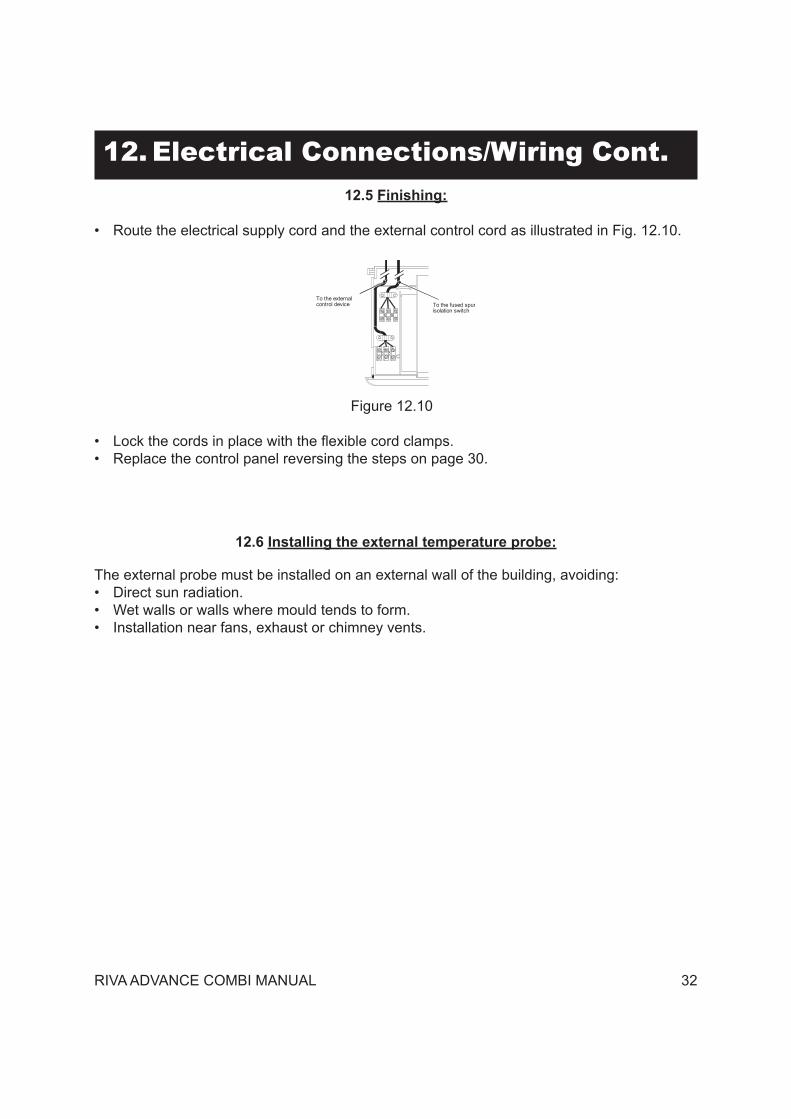
• Route the electrical supply cord and the external control cord as illustrated in Fig. 12.10.
Figure 12.10
• Lock the cords in place with the flexible cord clamps.• Replace the control panel reversing the steps on page 30.
To the fused spurTo the externalcontrol device
isolation switch
12.6 Installing the external temperature probe:
The external probe must be installed on an external wall of the building, avoiding:• Direct sun radiation.• Wet walls or walls where mould tends to form.• Installation near fans, exhaust or chimney vents.
33 RIVA ADVANCE COMBI MANUAL
12. Electrical Connections/Wiring Cont.12.7 Electric connection between the boiler and the external probe:
When connecting the external probe to the boiler, use electric wires with a minimum gauge of 18 AWG or section of 0.50 mm2.
The electric wires for connecting the external probe to the boiler must run through different grooves than those at network voltage (120 VAC), as they are powered at a low safety voltage and their maximum length must not exceed 66 feet or 20 meters.
• Remove the two screws shown in Figure 12.11 and open the external probe connection terminal board.
Figure 12.11
• Connect the two electric wires to terminals E1 and E2 on the terminal board as shown in Figure 12.12.
• Connect the same wires to the external probe terminals.
Figure 12.12
External probeconnectionterminal board
TO THE EXTERNAL PROBE
RIVA ADVANCE COMBI MANUAL 34
12. Electrical Connections/Wiring Cont.The path of the external probe wires or cable must follow the indicated path and be fastened as shown in Figure 12.13.
Figure 12.13 to
the
room
ther
mos
tat
to th
e bi
pola
rsw
itch
to th
eex
tern
al p
robe
to th
ere
mot
e co
ntro
l
12.8 Remote control electric connection (optional):
Unscrew the screws and remove the terminal board cover (Figure 12.11).See also the REMOTE CONTROL manual to connect the remote control to the boiler.
Figure 12.14
TO THE REMOTE
Remoteconnectionterminal board
Connect the two electric wires to terminals A and B on the terminal board as shown in Figure 12.14.The electric bridge connected in the room thermostat terminal board between terminals “1 and 3” must not be removed Figure 12.15.
Figure 12.15
13
Electric powersupply terminalboard
Roomthermostatterminal board
L N
35 RIVA ADVANCE COMBI MANUAL
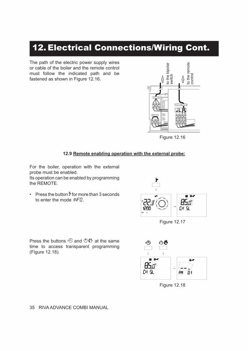
The path of the electric power supply wires or cable of the boiler and the remote control must follow the indicated path and be fastened as shown in Figure 12.16.
12. Electrical Connections/Wiring Cont.
Figure 12.16
to th
e bi
pola
rsw
itch
to th
e re
mot
eco
ntro
l
12.9 Remote enabling operation with the external probe:
For the boiler, operation with the external probe must be enabled.Its operation can be enabled by programming the REMOTE.
• Press the button for more than 3 seconds to enter the mode .
Figure 12.17
0
21
81
21
1 5
6
3
9
Press the buttons and at the same time to access transparent programming (Figure 12.18).
Figure 12.18
RIVA ADVANCE COMBI MANUAL 36
12. Electrical Connections/Wiring Cont.• Press the buttons or to display
the programming “PM15” external probe enabling (Figure 12.19).
Figure 12.19
• Change the programmed SET using the buttons or until a set of 60 is displayed, wait until the programmed number starts to flash (Figure 12.20).
Figure 12.20
• To exit programming, press .
37 RIVA ADVANCE COMBI MANUAL
13. Circulator Sizing13.1 Circulator capacity as a function of flow rate:
Figure 13.1
The hydraulic specification in Fig 13.1 represent the pressure (available head for the central heating system) as a function of the flow rate. The pressure loss due to the internal piping in the boiler has already been substracted.
When determining proper piping of the heating system, verify that the internal boiler circulator will overcome the head loss of the system at the designed flow rate using the graph above.If the internal circulator is adequate, direct system piping can be utilized. See section 14 page 41 for suggested direct supply/return piping.If the internal circulator is inadequate, a secondary circulator must be utilized. See sections 14 for suggested primary/secondary piping.
13.2 Expansion vessels:The height difference between the C.h. PRV (1 on page 11) and the highest point in the system may be 23 ft at most. For greater differences, increase the pre-load pressure in the C.h. expansion vessel (29 on page 11) and the system when cold, by 0.1 bar for additional 3.3 ft. For systems with volumes greater than 39 gallons (154 L), an additional expansion vessel must be provided.
All external piping components are to be supplied by the installer. The boiler, when used in connection with a refrigeration system, must be installed so the chilled medium is piped in parallel with the boiler with appropriate valves to prevent the chilled medium from entering the boiler. The boiler piping system of a hot water boiler connected to heating coils located in air handling units where they may be exposed to refrigerated air circulation must be equipped with �ow control valves or other automatic means to prevent gravity circulation of the boiler water during the cool-ing cycle.
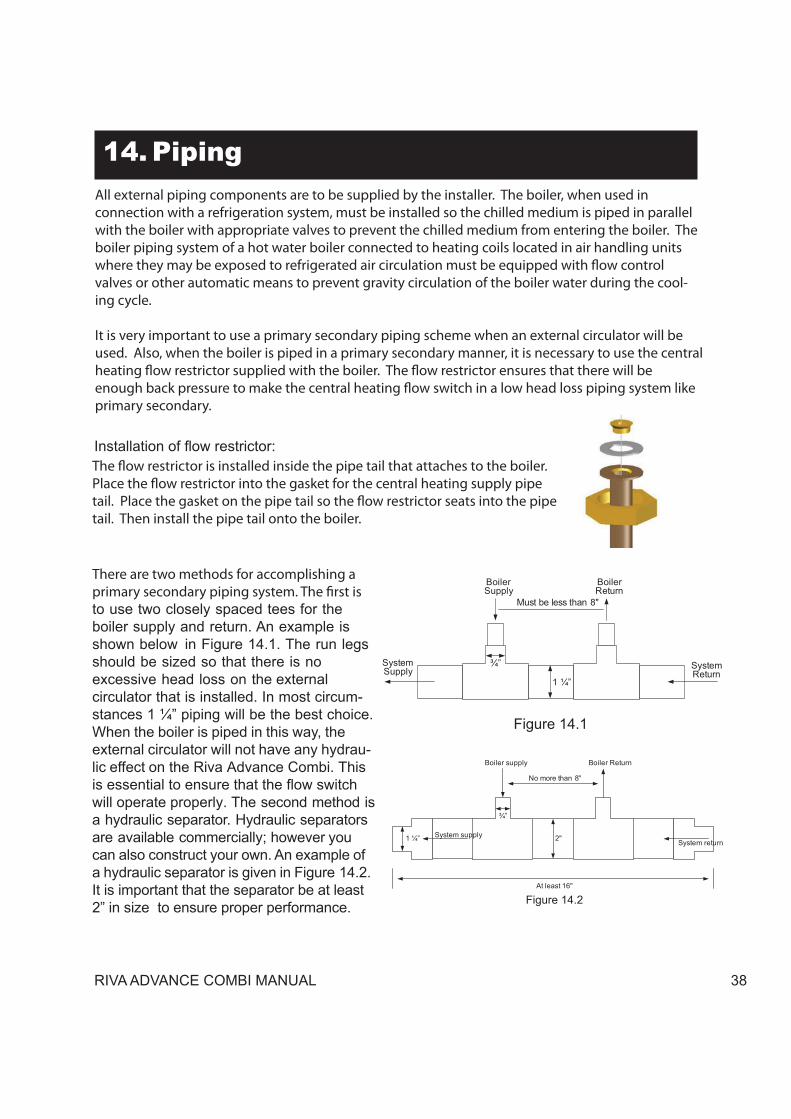
It is very important to use a primary secondary piping scheme when an external circulator will be used. Also, when the boiler is piped in a primary secondary manner, it is necessary to use the central heating �ow restrictor supplied with the boiler. The �ow restrictor ensures that there will be enough back pressure to make the central heating �ow switch in a low head loss piping system like primary secondary.
The �ow restrictor is installed inside the pipe tail that attaches to the boiler. Place the �ow restrictor into the gasket for the central heating supply pipe tail. Place the gasket on the pipe tail so the �ow restrictor seats into the pipe tail. Then install the pipe tail onto the boiler.
There are two methods for accomplishing a primary secondary piping system. The first is to use two closely spaced tees for the boiler supply and return. An example is shown below in Figure 14.1. The run legs should be sized so that there is no excessive head loss on the external circulator that is installed. In most circum-stances 1 ¼” piping will be the best choice. When the boiler is piped in this way, the external circulator will not have any hydrau-lic effect on the Riva Advance Combi. This is essential to ensure that the flow switch will operate properly. The second method is a hydraulic separator. Hydraulic separators are available commercially; however you can also construct your own. An example of a hydraulic separator is given in Figure 14.2. It is important that the separator be at least 2” in size to ensure proper performance.
RIVA ADVANCE COMBI MANUAL 38
39 RIVA ADVANCE COMBI MANUAL
14.1 Primary – Secondary Piping:
All external piping components are to be supplied by the installer.It is very important to use an hydraulic separator before secondary circulators.All external piping components are to be supplied by the installer.It is very important to use primary secondary piping or a hydraulic separator before secondary circulators.
Figure 14.3
14. Piping Cont.
RIVA ADVANCE COMBI MANUAL 40
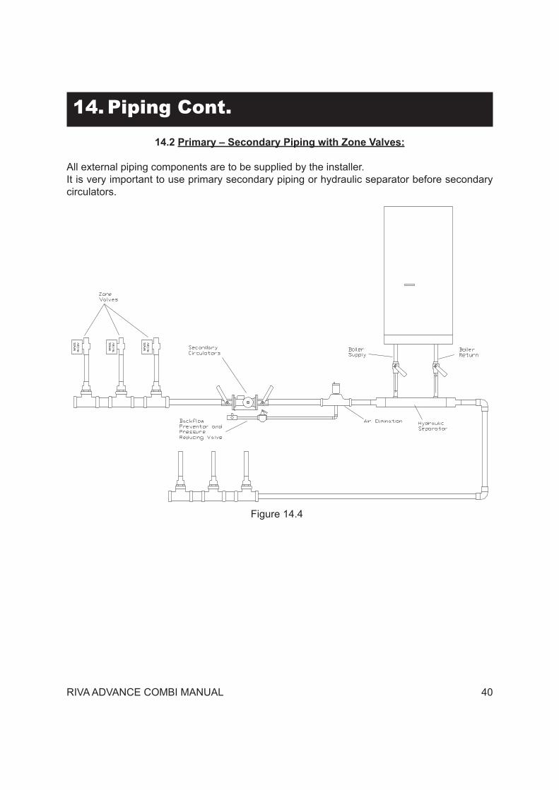
14.2 Primary – Secondary Piping with Zone Valves:
All external piping components are to be supplied by the installer.It is very important to use primary secondary piping or hydraulic separator before secondary circulators.
Figure 14.4
14. Piping Cont.
41 RIVA ADVANCE COMBI MANUAL
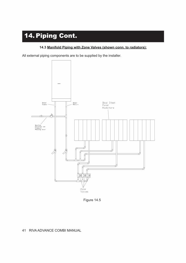
14.3 Manifold Piping with Zone Valves (shown conn. to radiators):
All external piping components are to be supplied by the installer.
Figure 14.5
14. Piping Cont.
15. Commissioning
WARNING
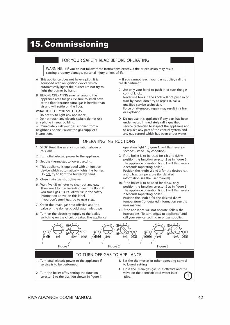
A This appliance does not have a pilot. It isequipped with an ignition device whichautomatically lights the burner. Do not try tolight the burner by hand.
B BEFORE OPERATING smell all around theappliance area for gas. Be sure to smell next
WHAT TO DO IF YOU SMELL GAS--- Do not try to light any appliance.--- Do not touch any electric switch; do not useany phone in your building.--- Immediately call your gas supplier from aneighbor’s phone. Follow the gas supplier’sinstructions.
--- If you cannot reach your gas supplier, call the
C Use only your hand to push in or turn the gascontrol knob.Never use tools. If the knob will not push in orturn by hand, don’t try to repair it, call a
or explosion.
D Do not use this appliance if any part has been
service technician to inspect the appliance andto replace any part of the control system andany gas control which has been under water.
FOR YOUR SAFETY READ BEFORE OPERATING
OPERATING INSTRUCTIONS1. STOP! Read the safety information above on
this label.
3. Set the thermostat to lowest setting.
4. This appliance is equipped with an ignitiondevice which automatically lights the burner.Do not try to light the burner by hand.
you smell gas STOP! Follow “B” in the safetyinformation above on this label.If you don’t smell gas, go to next step.
valve on the domestic cold water inlet pipe.
8. Turn on the electricity supply to the boiler,switching on the circuit breaker. The appliance
seconds (stand---by condition).9. If the boiler is to be used for c.h and d.h.w
position th
2 seconds (operating boiler).Position the knobs 2 and 3 for the desired c.h.and d.h.w. temperature (for detailedinformation see the user manual).
10.If the boiler is to be used for d.h.w. only
2 seconds (operating boiler).Position the knob 3 for the desired d.h.w.temperature (for detailed information see theuser manual).
11.If the appliance will not operate, follow theicall your service technician or gas supplier.
1 2 1 2 1 2Figure 1 Figure 2 Figure 3
TO TURN OFF GAS TO APPLIANCE
service is to be performed.3. Set the thermostat or other operating control
to lowest setting
valve on the domestic cold water inletpipe.
3 3
1
RIVA ADVANCE COMBI MANUAL 42
15. Commissioning15.1 For proper system operation, make
sure that:•
using softened water to reduce the total hardness. The water must also be conditioned in order to keep the pH within the foreseen threshold in order to prevent corrosion (see the following table).
• Both for new systems as well as when
systems that eliminate air and impurities
impurity separators and micro air bubble separators);
• Avoid draining system water during ordinary maintenance, even apparently
with suitable shut-off valves;• Always analyze the system water before
opening the communication between the new generator and the system in order to determine if the parameters of the water indicate the need to completely drain the system, to use the water already contained in the system or to chemically wash the system, using mains water with the addition of detergent, when it is suspected that the system could be dirty or particularly blocked, and the next time new water is loaded. If the analysis of a sample of the water that will be used for loading the system shows the following values, the system can be used. Otherwise, an inhibitor must be used.
9,6 < pH < 10,5Ca++ + Mg++ : <0,5 °FOH + 1/2 CO3 : de 5 à 15 °FP2O5 : de 10 à 30 mg/lNa2SO3 : de 20 à 50 mg/l
If the system water is also in contact with aluminum, a pH value <8.5 is required.
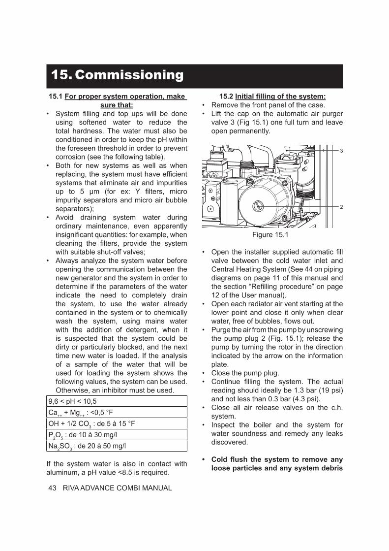
• Remove the front panel of the case.• Lift the cap on the automatic air purger
valve 3 (Fig 15.1) one full turn and leave open permanently.
Figure 15.1
• valve between the cold water inlet and Central Heating System (See 44 on piping diagrams on page 11 of this manual and
12 of the User manual).• Open each radiator air vent starting at the
lower point and close it only when clear
• Purge the air from the pump by unscrewing the pump plug 2 (Fig. 15.1); release the pump by turning the rotor in the direction indicated by the arrow on the information plate.
• Close the pump plug.•
reading should ideally be 1.3 bar (19 psi) and not less than 0.3 bar (4.3 psi).
• Close all air release valves on the c.h. system.
• Inspect the boiler and the system for water soundness and remedy any leaks discovered.
• loose particles and any system debris
2
3
43 RIVA ADVANCE COMBI MANUAL
15. Commissioning Cont.
time.
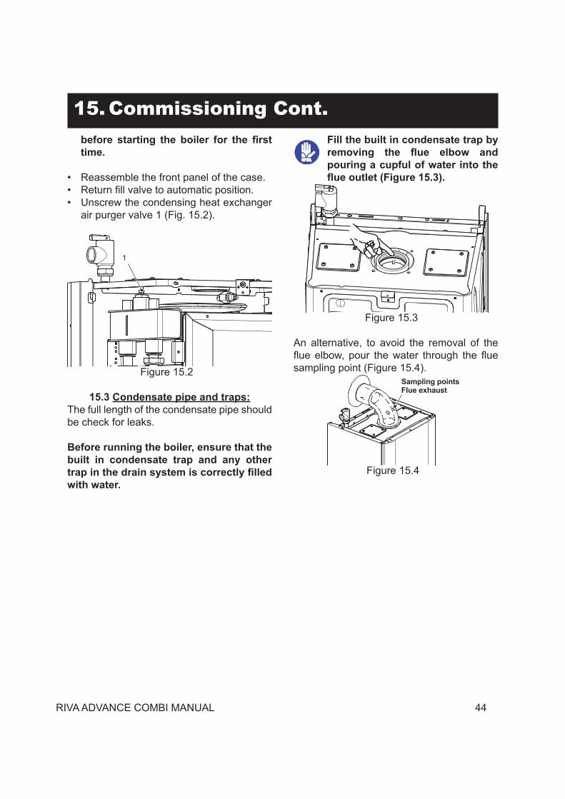
• Reassemble the front panel of the case.• • Unscrew the condensing heat exchanger
air purger valve 1 (Fig. 15.2).
Figure 15.2
1
15.3 Condensate pipe and traps:The full length of the condensate pipe should be check for leaks.
Before running the boiler, ensure that the built in condensate trap and any other
with water.
Fill the built in condensate trap by
pouring a cupful of water into the
Figure 15.3
An alternative, to avoid the removal of the
sampling point (Figure 15.4).
Figure 15.4
Sampling points Flue exhaust
RIVA ADVANCE COMBI MANUAL 44
45 RIVA ADVANCE COMBI MANUAL
15. Commissioning Cont.
Figure 15.5
Figure 15.6 8 7 6
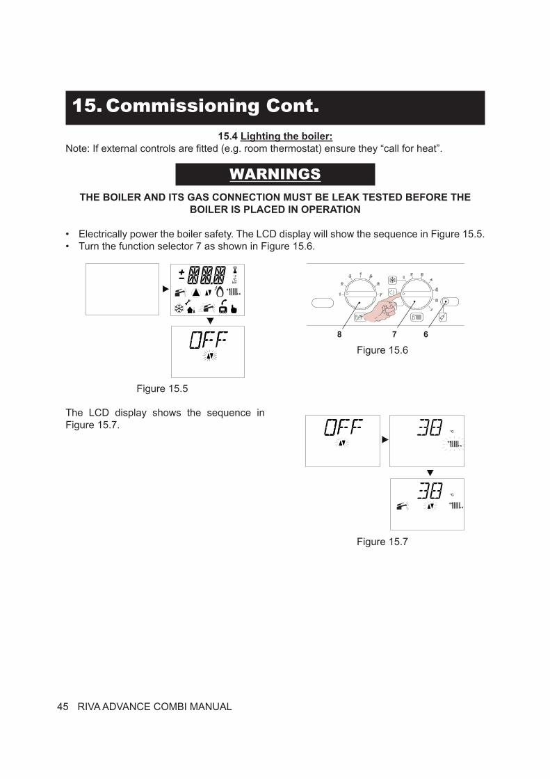
The LCD display shows the sequence in Figure 15.7.
15.4 Lighting the boiler:Note: If external controls are fitted (e.g. room thermostat) ensure they “call for heat”.
THE BOILER AND ITS GAS CONNECTION MUST BE LEAK TESTED BEFORE THE BOILER IS PLACED IN OPERATION
• Electrically power the boiler safety. The LCD display will show the sequence in Figure 15.5.• Turn the function selector 7 as shown in Figure 15.6.
WARNINGS
Figure 15.7
15. Commissioning Cont.
15.5 Checking the gas pressure at the burner:This boiler has been tested to the highest quality control standards.The maximum and minimum gas pressures are already set during this quality control process however the checking procedure must be followed to ensure maximum
Attention Each time after measuring the gas pressure, carefully reclose the tapping point that was used.Each time after making gas adjustments, the valve adjustment components must be sealed.
Attention, risk of electrocution.The boiler is powered during the operations described in this section. Do not touch any electric parts.
15.6 Gas setting and operations:
• Remove the front panel from the boiler body, see the section “Power Connection” on page 33.
Check the network pressure.• With the boiler shut off (out of service),
check the supply pressure at point C in Figure 15.16 and compare the read value with the value in the Gas supply pressure table in the section “Technical Information” page 9.
• Carefully reclose the tapping point C in Figure 15.16.
Check the min. burner pressure.•
analysis point on the boiler exhausts Figure 15.8.
Figure 15.8
Flue analysis points
• Position the control panel knobs as shown in Figure 15.9
The boiler will now go through an ignition sequence and the burner will light.If during the ignition attempt period the boiler fails to light, the full sequence control p.c.b. will go to lockout and the lock-out signal E1 will appear (See section “Operational Faults” on page 19 of the User manual).
“ position and then press and release the boiler reset button 6 (Fig. 15.6).
RIVA ADVANCE COMBI MANUAL 46
15. Commissioning Cont.
Figure 15.9 8 7 6
• Electrically power the boiler, the following will appear on the LCD display.
Figure 15.10
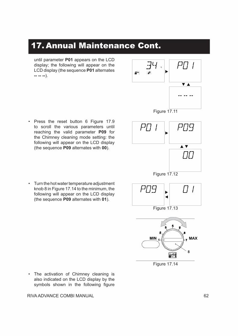
• To enter Chimney cleaning mode, enter programming by pressing the reset button 6 in Figure 15.9 for 10 seconds until parameter P01 appears on the LCD display; the following will appear on the LCD display (the sequence P01 alternates -- -- --).
Figure 15.11
• Press the reset button 6 Figure 15.9 to scroll the various parameters until reaching the valid parameter P09 for the Chimney cleaning mode setting: the following will appear on the LCD display (the sequence P09 alternates with 00).
Figure 15.12
• Turn the hot water temperature adjustment knob 8 in Figure 15.14 to the minimum, the following will appear on the LCD display (the sequence P09 alternates with 01.
Figure 15.13
Figure 15.14
MIN MAX
9
• The activation of Chimney cleaning also is indicated on the LCD display by the symbols shown in Figure 15.15 turning on alternately.
47 RIVA ADVANCE COMBI MANUAL
15. Commissioning Cont.
Figure 15.15
• Make sure that the display is indicating a heat request.
• Collect a large amount of domestic hot water by opening the cocks.
• Compare the CO2gas analyser with the one in the table CO2 at Q. min. section “Technical Information” page 9.
• To calibrate the boiler CO2 (burner gas pressure) completely unscrew the protective brass cap B and turn the Allen screw ø 4 mm below Figure 15.16, turning it clockwise increases the CO2.
Figure 15.16
A
B
C
Checking the maximum burner pressure.• Turn the hot water temperature knob 8 to
the maximum Figure 15.17 and check the CO2 value.
Figure 15.17
MIN MAX
8
• The LCD display signals the variation with the symbols shown in Figure 15.18 turning on alternately. (Example: heating thermal power at maximum).
Figure 15.18
• Compare the CO2 value read on the smoke analyser with the one in the table section “Technical Information” page 9. CO2 at Q. nom.
• If the two values do not coincide, turn the RQ maximum adjustment screw (A in Figure 15.16) on the gas valve and calibrate the CO2 to the same value shown in the table in the section “Technical Information” page 9. Turning it clockwise decreases the CO2.
• Check that the value of the CO2 at Q. min. does not lie outside of the value range in
RIVA ADVANCE COMBI MANUAL 48
RIVA ADVANCE COMBI MANUAL 49
15. Commissioning Cont.the table CO2 at Q. min. in the section “Technical Information” page 9.
• Close the domestic hot water cocks.• Turn off the boiler by positioning selector
7 to “ “ Figure 15.19.
Figure 15.19 7
When checking the minimum and maximum burner pressures, check the gas flow rate at the meter and compare its value with the gas flow rate data see section “Technical Information” page 9.
Reclose the flue analysis points.
15.7 Setting the external probe K coefficient:
The boiler is set with a K coefficient equal to zero for boiler operation without a connected probe.
Figure 15.20 External temperature °F
6868 59 50 41 32 23 14 5 -4 -13
86
104
122
140
158
176
C.h. flow temperature °FK=6 K=4 K=3 K=2
K=1,5
K=1
K=0,5
The K coefficient is a parameter that raises or lowers boiler delivery temperature as the external temperature changes.When the external probe is installed, this parameter must be set based on the heating system efficiency to optimise the delivery temperature (Figure 15.20)Ex. To achieve a delivery temperature to the heating system of 140°F (60°C) with an outdoor temperature of 23°F (-5°C), K must be set at 1.5 (dashed line in Figure 15.20).
Sequence for setting the K coefficient• Position the handles 8 and 7 indicated in
Figure 15.21.
Figure 15.21 8 7 6
• Electrically power the boiler, the following will appear on the LCD display.
Figure 15.22
• To set the K coefficient, which is determined from Figure 15.22 access programming by pressing the reset button 6 in Figure 15.2 for 15 seconds until parameter P01 appears on the LCD display; the following will appear on the LCD display (the
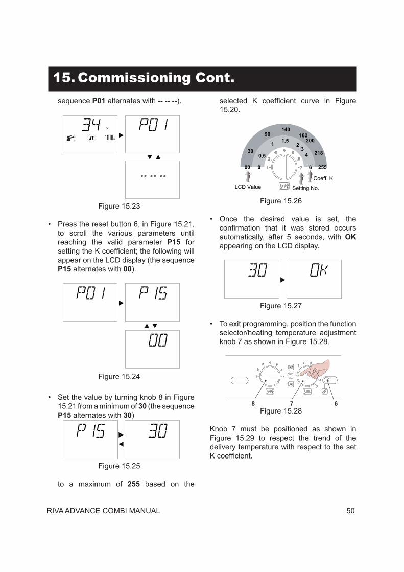
15. Commissioning Cont.sequence P01 alternates with -- -- --).
Figure 15.23
• Press the reset button 6, in Figure 15.21, to scroll the various parameters until reaching the valid parameter P15 for
appear on the LCD display (the sequence P15 alternates with 00).
Figure 15.24
• Set the value by turning knob 8 in Figure 15.21 from a minimum of 30 (the sequence P15 alternates with 30)
Figure 15.25
to a maximum of 255 based on the
Figure 15.20.
Figure 15.26
0
0,5
1 1,52
3
6
4
00
30
90140
182200
218
255
LCD ValueCoeff. K
Setting No.
• Once the desired value is set, the that it was stored occurs
automatically, after 5 seconds, with OK appearing on the LCD display.
Figure 15.27
• To exit programming, position the function selector/heating temperature adjustment knob 7 as shown in Figure 15.28.
Figure 15.28 8 7 6
Knob 7 must be positioned as shown in Figure 15.29 to respect the trend of the delivery temperature with respect to the set
RIVA ADVANCE COMBI MANUAL 50
RIVA ADVANCE COMBI MANUAL 51
15. Commissioning Cont.
Figure 15.29
Turning knob 7 can change the heating delivery temperature ± 27°F (15°C) with respect to the one set by the external probe K coefficient.
Figure 15.30
C.h. flowtemperature °F
External temperature °F
6868 59 50 41 32 23 14 5 -4 -13
86
104
122
140
158
176
K = 1,5
-15 °C
+ 15 °C
The temperature trend as the knob position is changed with K 1.5 is shown in Figure 15.30.
Sequence for setting the K coefficient with the remote connectedProgramming the REMOTE, the K coefficient setting can be selected.• Power the boiler electrically.• Press the button for more than 3 seconds
to enter the mode (Figure 15.31).
Figure 15.31
0
21
81
21
1 5
6
3
9
Press the button to display the K REG window (Figure 15.32).
Figure 15.32
The buttons and can be used to change the value.Press the button to exit the mode (Figure 15.32).
RIVA ADVANCE COMBI MANUAL 52
15. Commissioning Cont.15.8 Labels placement:
Figure 15.33
1
4
2
3
5
Warning: The installation is not complete unless labels supplied are placed on the boiler as shown in Figure 15.33.
All the labels supplied with the boiler are numbered for reference.According to Figure 15.33 place all the labels on the boiler. Use label numbered as 1 (already installed in the front panel) to begin the placement in the correct way.
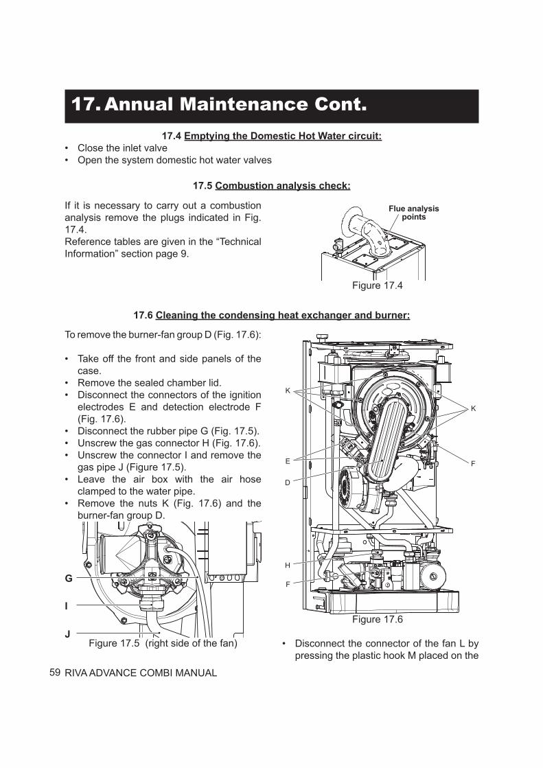
15.9 Checking the flue system and combustion:
• The flue system should be visually checked for soundness. Check all clamps, gaskets and fixings are secure and tight.
• Ensure that the flue terminal is sited correctly in accordance with the flue fitting instructions.
To check the exhaust gas:• Remove the plugs indicated (Fig. 15.34).• Insert the analyzer probe in the exhaust
gas sampling point or in the air intake sampling point.
• Reference tables are given in the Sections 2 on page 9 of this manual for proper CO2 levels.
RIVA ADVANCE COMBI MANUAL 53
Figure 15.34
Flue analysis points
15. Commissioning Cont.
15.10 Instructing the user:• Hand over the User manual, this Installation,Operation and Service manual to the end user
and explain how to use the unit in Central Heating mode.• Take the User step by step through the lighting instructions.• Show the User how to switch off the appliance quickly and indicate the position of the
electric service switch and the boiler on/off switch.• Explain the proper use and adjustment of all system controls; this will ensure the greatest
possible safety and fuel economy.• Explain the function and use of the function switch.• Explain how to turn off the appliance for both short and long periods and advise on the
precautions necessary to prevent damage should the appliance be inoperative when freezing conditions may occur.
• Fill in the details required on the Boiler Guarantee Certificate and hand to the User advising them to return the correct section for boiler Guarantee registration. Finally, advise the User that, for continued safe and efficient operation, the appliance must be serviced by a competent person at least once a year.
RIVA ADVANCE COMBI MANUAL 54
16. Gas Conversion
WARNINGS: Procedures to adapt the boiler to the type of gas available must be carried out by a competent and responsible person. Components used to adapt it to the type of gas available must be genuine parts only.
For instruction on calibrating the boiler gas valve see section “Operations and gas setting” on page 56.
Operations and gas settingCheck that the gas cock mounted on the gas piping to the boiler is closed and that the appliance is not powered.
• Remove the body’s front panel and turn the control panel as shown in section “Dismanteling the external panels” to page 60.
• Take off the lid of the sealed chamber.• Unscrew the connector A to the gas pipe
(Figure 16.1).
Figure 16.1
A
• Unscrew the connector B and remove the gas pipe C (Figure 16.2).
Figure 16.2
B
C
• Carry out gas conversion by correctly replacing the gas restrictor (Fig. 16.3), referring to the “Technical Information” section page 8.
Figure 16.3
Gas restrictor
Attention, to reassemble repeat the operations carried out in reverse order. Be careful not to damage the ring gasket of the gas pipe when inserting the pipe in the air box (air/gas mixer). After any service operation on the components of
RIVA ADVANCE COMBI MANUAL 55
16. Gas Conversion Cont.the gas circuit check all the connections for gas tightness (Figure 16.1).
The factory boiler is set for functioning with Natural gas (G20).
To set the functioning of the boiler with LPG (G31) gas, carry out the following settings:
Gas setting - first step• Disconnect the electric power supply from
the boiler.• Position the knobs 7 and 8 as shown in
Figure 16.4.
Figure 16.4 8 7 6
• Electrically power the boiler, the following will appear on the LCD display.
Figure 16.5
• To set the type of gas, enter programming by pressing the reset button 6 in Figure 16.4 for 15 seconds until parameter P01 appears on the LCD display; the following will appear on the LCD display (the sequence P01 alternates -- -- --).
Figure 16.6
• Press the reset button 6 Figure 16.4 to scroll the various parameters until reaching the valid parameter P05 for setting the type of gas; the following will appear on the LCD display (the sequence P05 alternates with 01).
Figure 16.7
• To change the setting, turn knob 8 and position it in the preselected position, see Figure 16.8
Figure 16.8
Gas type Gas type
NaturalGas
LPG
Setting No.
RIVA ADVANCE COMBI MANUAL 56
16. Gas Conversion Cont.
The following table summarises the correlation between gas type, knob set, LCD display.
GAS KNOB position LCD
Natural gas G20 1 01LPG G30-G31 7 07
Example: If the supplied gas is LPG (G30-G31) and the boiler is setup to operate with natural gas (G20) turn the knob 8 in Figure 16.4 as shown in Figure 16.9.
Figure 16.9
Gas type Gas type
NaturalGas
LPG
Setting No.
• The following will appear on the LCD display (the sequence P05 alternates with 07).
Figure 16.10
• Once the type of gas is set, the confirmation that it was stored occurs automatically, after 5 seconds, with OK appearing on the LCD display.
Figure 16.11
Gas setting - second step• Press the reset button 6 Figure 16.4
to access the valid parameter P06 for setting the type of gas (second level); the following will appear on the LCD display (the sequence P06 alternates with 01).
Figure 16.12
• To change the setting, turn the hot water temperature regulation knob 8 in Figure 16.4 to the preselected position see also Figure 16.9.
The following table summarises the correlation between gas type second level, knob set, LCD display.
GAS KNOB position LCD
Natural gas G20 1 01
LPG G30-G31 7 07
• The following will appear on the LCD display (the sequence P06 alternates with 07).
RIVA ADVANCE COMBI MANUAL 57
16. Gas Conversion Cont.
Figure 16.13
• To exit programming, position the function selector 7 to “ “ (Figure 16.14), or disconnect the electric power supply from the boiler.
Figure 16.14 7
• Calibrate the gas valve according to the instructions provided in the section “Operations and gas setting” on page 56.
• Reposition the controls panel and remount the front panel of the body.
• Apply the label indicating the gas nature and pressure value for which the appliance is regulated. The self adhesive label is contained in the conversion kit.
RIVA ADVANCE COMBI MANUAL 58
17. Annual Maintenance
17.1 Warnings:The procedures detailed in this chapter must be carried out only by a professionally qualified person. Thus you are advised to contact an Authorized Service Man.For efficient and continuous operation of the boiler you are advised to have, at least once a year, maintenance and cleaning done by an Approved Service Person.Isolate the appliance from the electricity supply by turning off the fused spur isolation switch adjacent to the appliance and turn off the gas cock, before carrying out any procedures, whatsoever, for cleaning, maintenance, opening or dismantling of boiler panels.
17.2 Dismanteling the external panels:Front Panel:• Loosen the three screws A (Fig. 17.1)• Lift and remove the panel.Side Panels:• Loosen the screws B (Figure 17.2). Bring the bottom of the panels away from the boiler and
lift them, freeing them from the top hooks.• Take off the front panel of the case, then the sealed chamber lid and the front panel of the
combustion chamber.
Figure 17.1
A
A
A
Figure 17.2
B
BB
B
• Close the pressure reducing automatic fill valve (43 on Section 4)
• Open the central heating drain cock (F in Fig. 17.3).
• Empty the c.h. system.• Close the central heating drain cock (F in
Fig. 17.3).• Open the pressure reducing automatic fill
valve (43 on Section 4) Figure 17.3
F
17.3 Emptying the d.h.w. system:
RIVA ADVANCE COMBI MANUAL 59
17. Annual Maintenance Cont.17.4 Emptying the Domestic Hot Water circuit:
• Close the inlet valve• Open the system domestic hot water valves
17.5 Combustion analysis check:
If it is necessary to carry out a combustion analysis remove the plugs indicated in Fig. 17.4.Reference tables are given in the “Technical Information” section page 9.
Figure 17.4
Flue analysis points
17.6 Cleaning the condensing heat exchanger and burner:
To remove the burner-fan group D (Fig. 17.6):
• Take off the front and side panels of the case.
• Remove the sealed chamber lid.• Disconnect the connectors of the ignition
electrodes E and detection electrode F (Fig. 17.6).
• Disconnect the rubber pipe G (Fig. 17.5).• Unscrew the gas connector H (Fig. 17.6).• Unscrew the connector I and remove the
gas pipe J (Figure 17.5).• Leave the air box with the air hose
clamped to the water pipe.• Remove the nuts K (Fig. 17.6) and the
burner-fan group D.
Figure 17.5 (right side of the fan)
I
G
JFigure 17.6
K
E
D
H
F
K
F
• Disconnect the connector of the fan L by pressing the plastic hook M placed on the
RIVA ADVANCE COMBI MANUAL 60
17. Annual Maintenance Cont.rear side of the connector (Fig. 17.7).
Figure 17.7
L
M
(rear view of the fan)
If you notice dirt on the coil of the condensing heat exchanger (24 on page 10) brush out it with a bristle paintbrush and remove the dust with a vacuum.Reassemble the parts carrying out the removal operations in reverse order.
17.7 Checking the pressurization in the expansion vessel:
Empty the central heating systemas described in section 17.3 of this chapter and check that the pressure in the expansion vessel is not less than 14 psi (1 bar).See also section 13.2 page 40 of this manual.If the pressure is lower, take steps to correct the pressure level.
17.8 Cleaning the burner:
with a bristle paintbrush.To reach the burner do the operations described in the section 17.6 of this manual.
checked periodically, at least once a year. During the check, the intake and exhaust screensshould be cleaned of any built up debris. To reassemble the vent follow the assembly instructionssupplied with the venting system. All gaskets used in the assembly are reusable, however if any need to be replaced, they must be OEM replacements. Silicon lubricant can be used to ease the reassembly of the vent system.
17.10 Drain pipe inspection:Check the soundness and integrity of the condensate drain pipe.
17.11 Visual inspection of appliance:Visually inspect all water joints, seals and connections for any evidence of leakage and retighten, grease or replace them as necessary.
17.12 Gas pressures and soundness:
Check appliance for gas soundness. Recheck operational pressures as described in section 15.5 page 48 of this manual.
RIVA ADVANCE COMBI MANUAL 61
17. Annual Maintenance Cont.17.13 Water inhibitor concentration:
Where chemical products are used the level of water treatment should be checked on an annual basis and re treated after full or partial drain down.A conductivity meter can be used to check the correct concentration of inhibitor in the heating water. See the section 15.1 of this handbook.
17.14 Checking the condensate drain pipe:
The condensate drain system should be checked yearly during a service. Check:• That no solid deposits have formed, if so
remove them.•
Remove the forks E and remove the condensate trap A moving it downwards (Fig. 17.8).
Figure 17.8
A
D
E
17.16 Setting the boiler chimney sweep function:
With the boiler set in chimney sweep mode, it is possible to exclude some boiler automatic functions making check and control operations easier.
• Position the control panel knobs as shown in Figure 17.9.
Figure 17.9 8 7 6
•
Electrically power the boiler, the following will appear on the LCD display.
Figure 17.10
• To enter Chimney cleaning mode, enter programming by pressing the reset button 6 in Figure 17.9 for 15 seconds
That the condensate drain piping is not clogged, if so clear the clog.
Unscrew the plug D to clean inside the pipe.Removal
•
17.15 Checking Low Water Cutoff
If a low water cutoff is installed on a system, it’s function should be checked as part of the yearly service. Refer to the low water cutoff manufacturers instructions for maintenance and testing.
•
k.hnatow
Typewritten Text
k.hnatow
Typewritten Text
k.hnatow
Typewritten Text
k.hnatow
Typewritten Text
k.hnatow
Typewritten Text
k.hnatow
Typewritten Text
RIVA ADVANCE COMBI MANUAL 62
17. Annual Maintenance Cont.until parameter P01 appears on the LCD display; the following will appear on the LCD display (the sequence P01 alternates -- -- --).
Figure 17.11
• Press the reset button 6 Figure 17.9 to scroll the various parameters until reaching the valid parameter P09 for the Chimney cleaning mode setting: the following will appear on the LCD display (the sequence P09 alternates with 00).
Figure 17.12
• Turn the hot water temperature adjustment knob 8 in Figure 17.14 to the minimum, the following will appear on the LCD display (the sequence P09 alternates with 01).
Figure 17.13
Figure 17.14
MIN MAX
8
• The activation of Chimney cleaning is also indicated on the LCD display by the symbols shown in the following figure
RIVA ADVANCE COMBI MANUAL 63
17. Annual Maintenance Cont.turning on alternately.
Figure 17.15
• The heating thermal power can be changed by turning the hot water temperature adjustment knob 8 shown in Figure 17.16.
Figure 17.16
MIN MAX
8
• The LCD display signals the variation with the symbols shown in the following figure turning on alternately. (Example: heating thermal power at maximum).
Figure 17.17
• To exit programming, position selector 8 as shown in Figure 17.18.
Figure 17.18 10
After 15 minutes, the boiler exits from the Chimney cleaning setting and returns to its normal settings.
RIVA ADVANCE COMBI MANUAL 64
18. Vent Part Spares Cont.18.2 Coaxial venting:
Description Order Number
Coaxial flue kit 10999.0387.0
For any spare parts, please contact QHT Inc. at 800-501-7697.
RIVA ADVANCE COMBI MANUAL 65
18. Vent Part Spares Cont.18.4 Separate PVC venting:
For any spare parts, please contact QHT Inc. at 800-501-7697.
Description Order Number
PVC Boiler Adapter PTA5808
66 RIVA ADVANCE COMBI MANUAL
18. Vent Part Spares Cont.18.5 PVC Sidewall venting:
For any spare parts, please contact QHT Inc. at 800-501-7697.
Description Order Number
PVC Boiler Adapter RI - 10 0887
RIVA ADVANCE COMBI MANUAL 67
18. Vent Part Spares Cont.
Description Order Number
PVC Boiler Adapter RI - 10 0885
18.6 PVC Roof venting:
For any spare parts, please contact QHT Inc. at 800-501-7697.
18. Spare Parts18.x Boiler spares:
For any spare parts, please contact QHT Inc. at 800-501-7697.