1) Replace the + by the code letter “C” or “J” for the required version.
B65805RM 5Core
200 Siemens Matsushita Components
Coil former
Material: GFR thermosetting plastic (UL 94 V-0, insulation class to IEC 60085:H max. operating temperature 180 °C), color code black
Solderability: to IEC 60068-2-20, test Ta, method 1 (aging 3): 235 °C, 2 sResistance to soldering heat: to IEC 60068-2-20, test Tb, method 1B: 350 °C, 3,5 sWinding: see page 152Squared pinsFor matching clamps and insulating washers see page 201
4 pins 5 and 6 pins 8 pins
Sections ANmm2
lNmm
AR valueµΩ
Pins Ordering code
1 9,5 25 90 4 B65806-N1004-D1
5 B65806-N1005-D1
6 B65806-N1006-D1
8 B65806-N1008-D1
2 8,7 25 94 4 B65806-N1004-D2
5 B65806-N1005-D2
6 B65806-N1006-D2
Hole arrangementView in mounting direction
*) Pin 4 is omitted in 5-pin version.
Ground Ø 1,3+0,1
RM 5Accessories B65806
Siemens Matsushita Components 201
Clamp
With ground terminal, made of stainless spring steel (tinned), 0,335 mm thick Solderability to IEC 60068-2-20, test Ta, method 1 (aging 3): 235 °C, 2 s Also available as strip clamp on reels
Insulating washer 1 between core and coil former
For tolerance compensation and for insulation Made of polycarbonate (UL 94 V-0, insulation class to IEC 60085: E 120 °C), 0,06 mm thick
Insulating washer 2 for double-clad PCBs
Made of polycarbonate (UL 94 V-0, insulation class to IEC 60085: E 120 °C), 0,3 mm thick
Clamp Insulating washer 1 Insulating washer 2
Clamping forces for RM 5
Ordering code
Clamp (ordering code per piece, 2 are required) B65806-A2203
Insulating washer 1 (reel packing, PU = 1 reel) B65806-A5000
Insulating washer 2 (bulk) B65806-D2005
Fmin: Extension of clamp from a to a2 = XminFmax: Extension of clamp from a to a1 = Xmax
Clamp opening a (mm) 8,3 + 0,15
Core nose Zmax (mm) 0,15
Height of core pair X (mm)XminXmax
8,759,25
Clamping force F (N) FminFmax
540
B65806RM 5Accessories
202 Siemens Matsushita Components
SMD coil former with gullwing terminals
Material: GFR liquid crystal polymer (UL 94 V-0, insulation class to IEC 60085:F max. operating temperature 155 °C), color code black
Solderability: to IEC 60068-2-20, test Ta, method 1 (aging 3): 235 °C, 2 sResistance to soldering heat: to IEC 60068-2-20, test Tb, method 1B: 350 °C, 3,5 s
permissible soldering temperature for wire-wrap connection on coil former: 400 °C,1 sWinding: see page 160
Clamp
Without ground terminal, made of stainless spring steel, 0,3 mm thick Also available as strip clamp (each carton containing 2 reels), also on a reel on request
Coil former Clamp
Sections ANmm2
lNmm
AR valueµΩ
Terminals Ordering code
1 11,1 25 77 8 B65822-F1008-T1
2 10,2 25 85 8 B65822-F1008-T2
Clamp (ordering code per piece, 2 are required) B65806-J2204
RecommendedPCB layout
1 section 2 sections
RM 5Accessories
B65822B65806
Siemens Matsushita Components 203
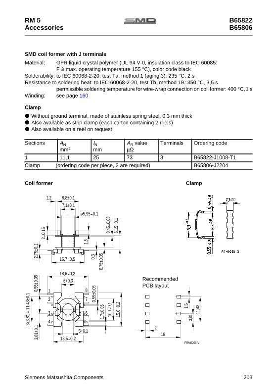
SMD coil former with J terminals
Material: GFR liquid crystal polymer (UL 94 V-0, insulation class to IEC 60085:F max. operating temperature 155 °C), color code black
Solderability: to IEC 60068-2-20, test Ta, method 1 (aging 3): 235 °C, 2 sResistance to soldering heat: to IEC 60068-2-20, test Tb, method 1B: 350 °C, 3,5 s
permissible soldering temperature for wire-wrap connection on coil former: 400 °C,1 sWinding: see page 160
Clamp
Without ground terminal, made of stainless spring steel, 0,3 mm thick Also available as strip clamp (each carton containing 2 reels) Also available on a reel on request
Coil former Clamp
Sections ANmm2
lNmm
AR valueµΩ
Terminals Ordering code
1 11,1 25 73 8 B65822-J1008-T1
Clamp (ordering code per piece, 2 are required) B65806-J2204
FRM0266-V
0,55
±0,0
52,
75±0
,1 1,5
0,3
0,45
±0,0
5
0,75
±0,0
5
7,1±0,1
6+0,3
1
2
3
4
8
7
6
5
0,55
±0,0
5
1,7±
0,05
3,81
±0,1
3x3,
81 =
11,
43±0
,1
LeiterplattenlayoutEmpfehlung für das
1,5
11,4
3
3,81
216
9,8±0,11,2
5+0,1
0,1ø5,95 _
_6,
150,
1
0,15
2_
15,7 _0,5
0,2_18,6
13,5 _0,2
10,1
_ 0,1
0,2
_15
,0
RecommendedPCB layout
B65822B65806
RM 5Accessories
204 Siemens Matsushita Components
Adjusting screw Tube core with thread and core brake made of GFR polyterephthalatePlastic adjusting screwdriver (not shown)Plastic handle for adjusting screwdriver (not shown)
Adjusting screwsa b
Core RM 5 Adjusting screw Min.adjustingrange
%
Ordering code
Fig. Tube coreMate-rial
AL valuenH
∅ × lengthmm
Mate-rial
Colorcode
K 1 25 a 1,81 × 2,0 Si 1 black 13 B65539-C1003-X101
40 a 1,81 × 2,0 K 1 yellow 16 B65539-C1003-X1
M 33 63 a 1,81 × 2,7 Si 1 white 11 B65539-C1002-X101
100 a 1,81 × 2,0 K 1 yellow 14 B65539-C1003-X1
N 48 125 a 1,81 × 2,0 K 1 yellow 13 B65539-C1003-X1
160200
a 1,81 × 2,7 N 22 red 1511
B65539-C1002-X22
250315
b 1,81 × 3,4 N 22 green 139
B65806-C3001-X22
315 b 1,90 × 3,4 N 22 blue 12 B65806-A3002-X22
Adjusting screwdriver B63399-B4
Handle B63399-B5
RM 5Accessories
B65539B63399, B65806
Siemens Matsushita Components 205
Inductance adjustment curves (nominal values)
Relative inductance change ∆ L/L versus turns N of adjusting screw.0 at least 1 turn engaged.
Adjusting screw B65539-C1003-X101Color code black
Adjusting screw B65539-C1003-X1Color code yellow
Adjusting screw B65539-C1002-X101Color code white
RM 5
206 Siemens Matsushita Components
Inductance adjustment curves (nominal values)
Relative inductance change ∆ L/L versus turns N of adjusting screw.0 at least 1 turn engaged.
Adjusting screw B65539-C1002-X22Color code red
Adjusting screw B65806-A3002-X22Color code blue
Adjusting screw B65806-C3001-X22Color code green
RM 5
Siemens Matsushita Components 207
Q factor characteristics (typical values)
Mate-rial
L (µH) for Turns Wire; RF litz wire Sec-tions
∅*mmAL= 25 nH AL= 40 nH
K 1 1,274,25
15,710,2
1,966,75
2516
7132520
0,6 CuL30 × 0,04 CuLS30 × 0,04 CuLS40 × 0,04 CuLS
1111
8,59,08,48,2 * Pad of
polystyrenetape up todiameter Ø
K 1AL= 25 nHFlux densityin the core
< 0,5 mTB
RF litz wireEnamel copperwire
K 1AL= 40 nHFlux densityin the core
< 0,6 mTB
RF litz wireEnamel copperwire
RM 5
208 Siemens Matsushita Components
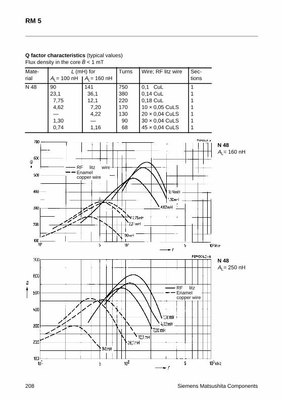
Q factor characteristics (typical values)Flux density in the core < 1 mT
Mate-rial
L (mH) for Turns Wire; RF litz wire Sec-tionsAL= 100 nH AL= 160 nH
Material: GFR liquid crystal polymer (UL 94 V-0, insulation class to IEC 60085:F max. operating temperature 155 °C), color code black
Solderability: to IEC 60068-2-20, test Ta, method 1 (aging 3): 235 °C, 2 sResistance to soldering heat: to IEC 60068-2-20, test Tb, method 1B: 350 °C, 3,5 s
permissible soldering temperature for wire-wrap connection on coil former: 400 °C,1 sWinding: see page 160
Clamp
Without ground terminal, made of stainless spring steel, 0,3 mm thick Also available as strip clamp (each carton containing 2 reels) Also available on a reel on request
Coil former Clamp
Sections ANmm2
lNmm
AR valueµΩ
Terminals Ordering code
1 5,1 25 169 8 B65822-A6008-T1
Clamp (ordering code per piece, 2 are required) B65804-P2204