6.2.5.1 AC Solid State Relays ......................................................................................................................... 27 6.2.5.2 AC Solid State Relay Heatsinks ......................................................................................................... 28 6.2.5.3 Mercury Displacement Relays ............................................................................................................ 29 6.2.5.4 DRT1 Dual Relay Timer Wiring ........................................................................................................ 30
6.2.6 Measurement Type Wiring ..................................................................................................................... 31 6.2.6.1 Rectifier Measurement Type Diagrams .............................................................................................. 32 6.2.6.2 Test Point Measurement Type Diagrams ............................................................................................ 39 6.2.6.3 Bond Measurement Type Diagrams ................................................................................................... 42 6.2.6.4 Field Installable User Label Set (RMU3-B only) ............................................................................... 46 6.2.6.5 Measurement Wiring Connections...................................................................................................... 47
6.3 Interconnection Cable ..................................................................................................................................... 47 6.4 Startup and Verification .................................................................................................................................. 48 6.5 Status LED ...................................................................................................................................................... 48
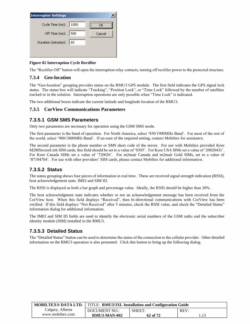
7.3.5.1 GSM SMS Parameters ........................................................................................................................ 62 7.3.5.2 Status .................................................................................................................................................. 62 7.3.5.3 Detailed Status .................................................................................................................................... 62 7.3.5.4 Test Transmission ............................................................................................................................... 63
7.3.6 RMU3 Communications and Status ........................................................................................................ 63 7.4 Post Configuration .......................................................................................................................................... 64
MOBILTEX® DATA LTD.
Calgary, Alberta
www.mobiltex.com
TITLE: RMU3/3XL Installation and Configuration Guide
DOCUMENT NO.:
RMU3-MAN-002
SHEET:
4 of 72
REV:
1.13
8 Mobile Device Configuration ................................................................................................................................. 65 9 Servicing ................................................................................................................................................................. 67 A. Equipment Specifications ................................................................................................................................... 68
Figures
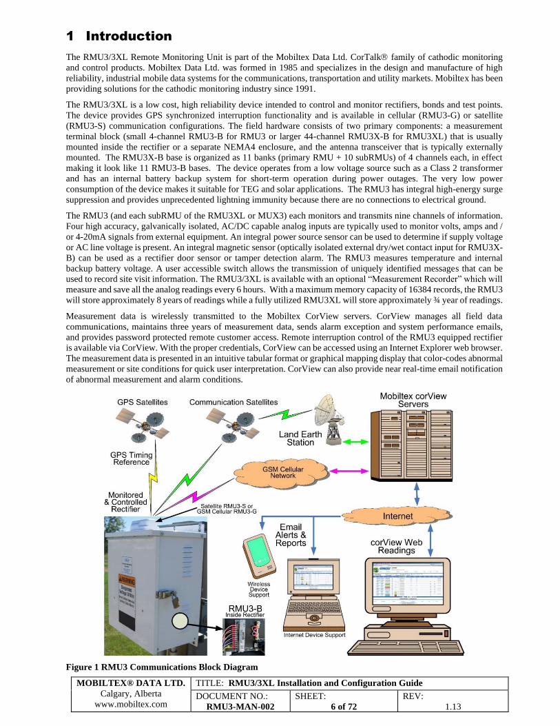
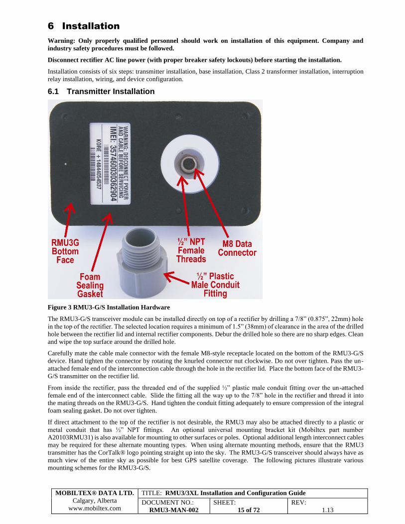
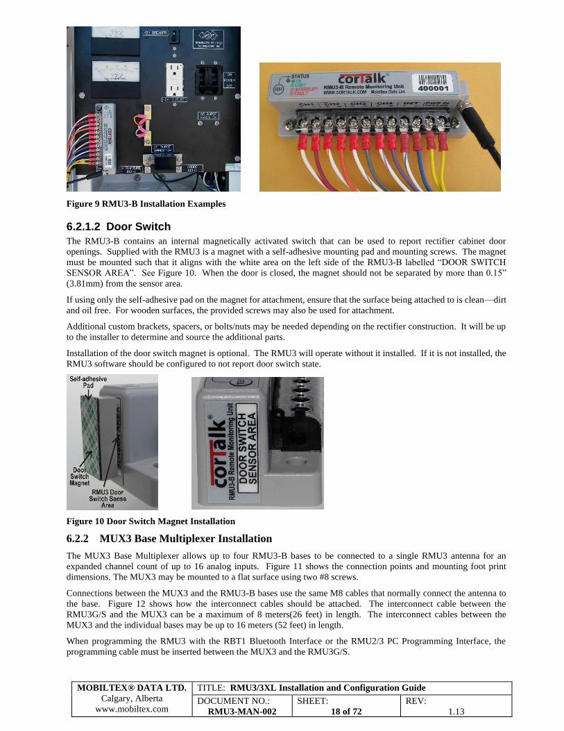
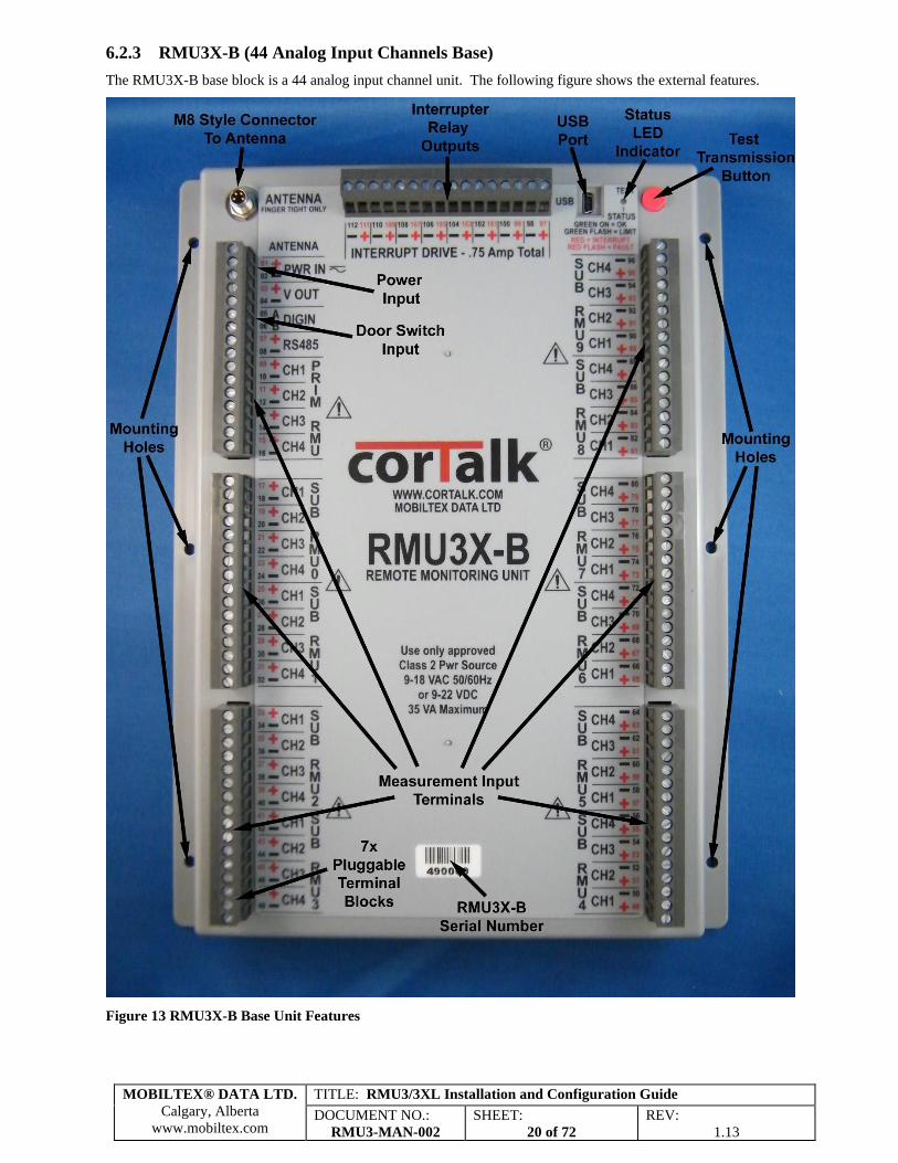
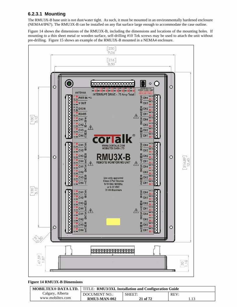
Figure 1 RMU3 Communications Block Diagram ........................................................................................................... 6 Figure 2 CorView All Readings Page............................................................................................................................. 14 Figure 3 RMU3-G/S Installation Hardware .................................................................................................................... 15 Figure 4 RMU3-G/S Installation Examples .................................................................................................................... 16 Figure 5 RMU3-G/S Conduit Nut Spacing ..................................................................................................................... 16 Figure 6 RMU3-G/S Conduit Punch Though Example .................................................................................................. 16 Figure 7 RMU3-B Base Unit Features ........................................................................................................................... 17 Figure 8 RMU3-B Installation Hardware ...................................................................................................................... 17 Figure 9 RMU3-B Installation Examples ....................................................................................................................... 18 Figure 10 Door Switch Magnet Installation.................................................................................................................... 18 Figure 11 MUX3 Base Multiplexer Features.................................................................................................................. 19 Figure 12 MUX3 Cable Connections ............................................................................................................................. 19 Figure 13 RMU3X-B Base Unit Features ....................................................................................................................... 20 Figure 14 RMU3X-B Dimensions .................................................................................................................................. 21 Figure 15 RMU3X-B Mounted in a NEMA4 Enclosure ................................................................................................ 22 Figure 16 RMU3X-B Door Switch Wiring .................................................................................................................... 22 Figure 17 Mobiltex 12VAC Output Class 2 Transformer .............................................................................................. 23 Figure 18 Mechanical and Mercury Displacement Relay Installation ............................................................................ 25 Figure 19 AC Solid State Triac Relay Installation ......................................................................................................... 25 Figure 20 DC Solid State MOSFET Relay Installation .................................................................................................. 26 Figure 21 RMU3X-B Interruption Relay Connections ................................................................................................... 26 Figure 22 Mobiltex Standard Single Phase Solid State AC Relays ................................................................................ 27 Figure 23 Mobiltex Standard Three Phase AC Solid State Relay .................................................................................. 27 Figure 24 X030120HE54 Medium Heatsink .................................................................................................................. 28 Figure 25 X030320HE90 Large Heatsink ...................................................................................................................... 28 Figure 26 Mercury Displacement Relay Contact De-rating ........................................................................................... 29 Figure 27 K07111NC12D 100A Mercury Displacement Relay ..................................................................................... 29 Figure 28 DRT1 Dual Relay Timer Module ................................................................................................................... 30 Figure 29 Measurement Types ....................................................................................................................................... 31 Figure 30 RECT1 Rectifier – Output Volts, Total Amps, and 2 Drains ......................................................................... 32 Figure 31 RECT2 Rectifier – Output Volts and 3 Drains ............................................................................................... 33 Figure 32 RECT3 Rectifier – Output Volts, Total Amps, Drain, and Input AC Volts ................................................... 33 Figure 33 RECT4 Rectifier - Output Volts, 2 Drains, and Input AC Volts .................................................................... 34 Figure 34 RECT5 Rectifier – Output Volts, Total Current, and Pipe-To-Soil AC/DC .................................................. 34 Figure 35 RECT6 Rectifier – Output Volts, Total Current, Pipe-To-Soil and Input AC Volts ...................................... 34 Figure 36 RECT7 Rectifier – Output Volts AC/DC, Total Current, and Input AC Volts .............................................. 35 Figure 37 RECT8 Rectifier – Output Volts AC/DC, Total Current, and Pipe-To-Soil .................................................. 35 Figure 38 RECT9 TEG or Solar – Output Volts, Total Current, Drain, and Input DC Volts ......................................... 36 Figure 39 RECT10 TEG or Solar – Output Volts, 2 Drains, and Input DC Volts .......................................................... 36 Figure 40 RECT11 TEG or Solar – Output Volts, Total Current, Pipe-To-Soil, and Input DC Volt ............................. 37 Figure 41 RECT12 Two Co-located Rectifiers – Rect #1/2 Output Volts, and Rect #1/2 Current ................................ 37 Figure 42 RECT13 Rectifier – Output Volts, Total Current, and 2 Pipe-To-Soil DC .................................................... 38 Figure 43 RECT14 Rectifier – Output Volts, Total Current, 1 Pipe-To-Soil DC, and 1 Bond Current DC ................... 38 Figure 44 RECT15 Rectifier – Output Volts, Total Current, Input AC Amps and Input AC Volts ............................... 39 Figure 45 TP17 Testpoint – Pipe-To-Soil DC/AC, AC Mitigation Current, and AC Current Density .......................... 39 Figure 46 TP18 Testpoint – Pipe-To-Soil DC/AC, DC Current Density, and AC Current Density ............................... 40 Figure 47 TP19 Testpoint – Pipe-To-Soil 1 DC/AC, Pipe-To-Soil 2 DC, and AC Current Density .............................. 40 Figure 48 TP20 Testpoint – 4 Pipe-To-Soil DC ............................................................................................................. 41 Figure 49 TP21 Testpoint – 2 Pipe-To-Soil AC/DC ...................................................................................................... 41 Figure 50 BOND22 Bond – 2 Pipe-To-Soil, and 2 Bond Currents ................................................................................ 42 Figure 51 BOND23 Bond – Pipe-To-Soil, and 3 Bond Currents ................................................................................... 42 Figure 52 BOND24 Bond – Pipe-To-Soil AC/DC, and 2 Bond Currents ...................................................................... 43 Figure 53 BOND25 Bond – 2 Pipe-To-Soil AC/DC ...................................................................................................... 43 Figure 54 BOND26 Bond – 4 Bond Currents ................................................................................................................. 44
MOBILTEX® DATA LTD.
Calgary, Alberta
www.mobiltex.com
TITLE: RMU3/3XL Installation and Configuration Guide
DOCUMENT NO.:
RMU3-MAN-002
SHEET:
5 of 72
REV:
1.13
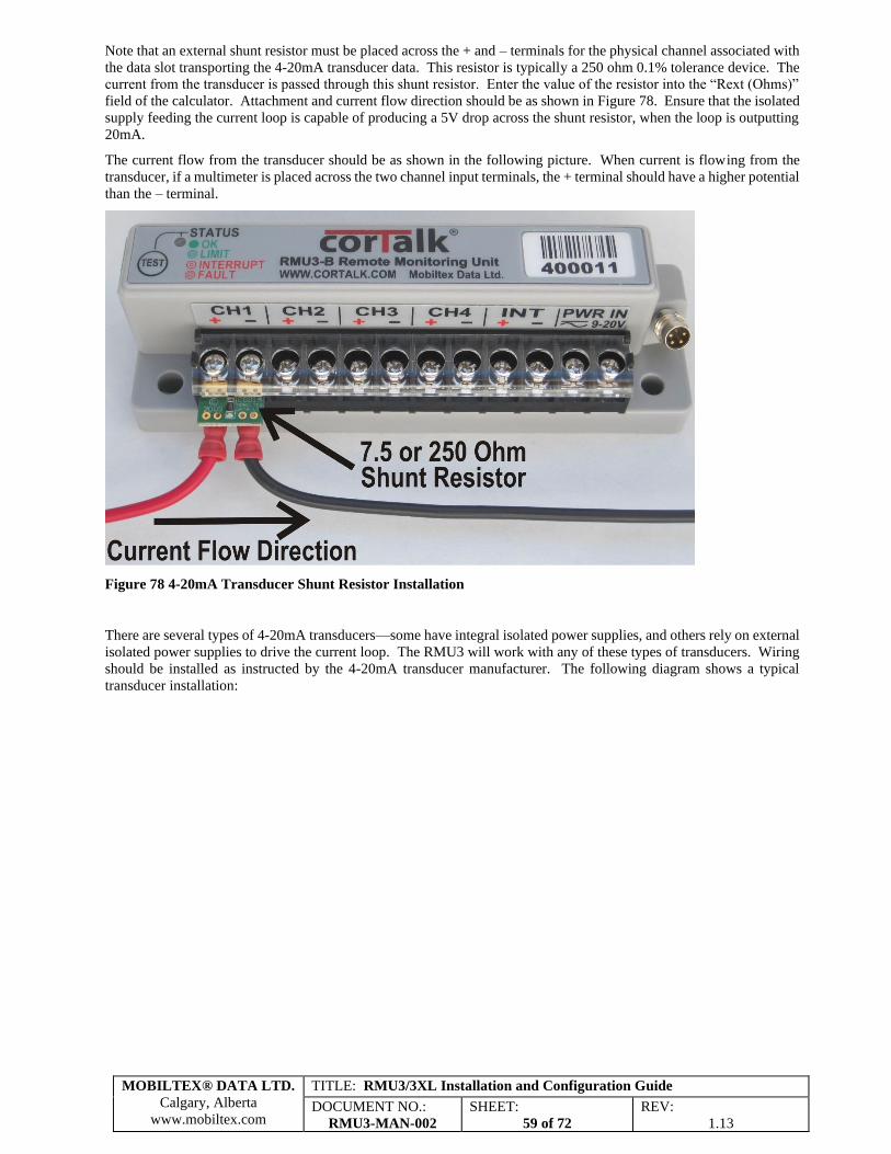
Figure 55 BOND27 Bond – Pipe-To-Soil DC/AC, 1 Bond Current, and AC Mitigation Current ................................. 44 Figure 56 BOND28 Bond – Pipe-To-Soil DC, 2 Bond Currents, and AC Mitigation Current ....................................... 45 Figure 57 BOND29 Bond – Three Pipe-To-Soil DC, 1 Bond Current ........................................................................... 45 Figure 58 BOND30 Bond – Pipe-To-Soil 1 DC/AC, Pipe-To-Soil 2 DC, and AC Mitigation Current ......................... 46 Figure 59 Field Installable User Label Set ..................................................................................................................... 46 Figure 60 Example of Label on Bottom of Terminal Block ........................................................................................... 47 Figure 61 Example of Label on Top of Terminal Block ................................................................................................. 47 Figure 62 RMU3 LED Status Indicator .......................................................................................................................... 49 Figure 63 RMU1/2/3 Configuration Interface ................................................................................................................ 50 Figure 64 RMU3 Configuration Interface Bottom View ................................................................................................ 51 Figure 65 RMUInstaller Dialog ...................................................................................................................................... 51 Figure 66 RMU3ConfigSetup.msi Security Warning Dialog ......................................................................................... 52 Figure 67 RMU3 Configuration Application Installation Dialog ................................................................................... 52 Figure 68 RMU3 Configuration Application Installation Complete .............................................................................. 53 Figure 69 Driver Installation Screen ............................................................................................................................... 53 Figure 70 Driver Installation - Found New Hardware .................................................................................................... 54 Figure 71 Driver Installation - Install From Specific Location....................................................................................... 54 Figure 72 Driver Installation - Driver Location Selection .............................................................................................. 55 Figure 73 Driver Installation - Driver File Search .......................................................................................................... 55 Figure 74 RMU3 Configuration Application Dialog ...................................................................................................... 56 Figure 75 RMU3 Configuration Application With SubRMUs Enabled ......................................................................... 56 Figure 76 Current Shunt Calculator Dialog .................................................................................................................... 58 Figure 77 4-20mA Transducer Calculator ...................................................................................................................... 58 Figure 78 4-20mA Transducer Shunt Resistor Installation ............................................................................................ 59 Figure 79 4-20mA Transducer Typical Installation ........................................................................................................ 60 Figure 80 Pre-defined Relay Type Selection Dialog ...................................................................................................... 61 Figure 81 Interruption Rectifier Status ........................................................................................................................... 61 Figure 82 Interruption Cycle Rectifier............................................................................................................................ 62 Figure 83 GSM SMS Detailed Status ............................................................................................................................. 63 Figure 84 RBT1 Bluetooth Interface Cable .................................................................................................................... 65 Figure 85 RMU1/2/3 Programming Interface................................................................................................................. 65 Figure 86 iOS App Sample Screenshots ......................................................................................................................... 66
TITLE: RMU3/3XL Installation and Configuration Guide
DOCUMENT NO.:
RMU3-MAN-002
SHEET:
30 of 72
REV:
1.13
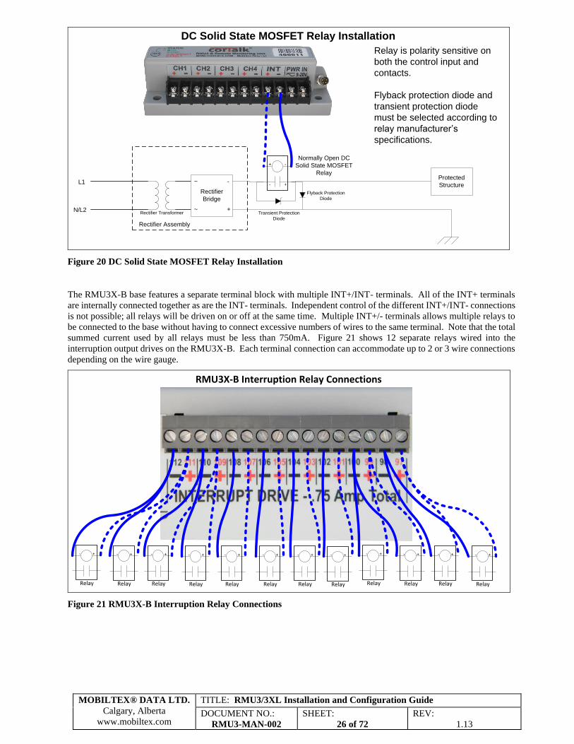
6.2.5.4 DRT1 Dual Relay Timer Wiring
The DRT1 is meant to replace a solid-state relay with a dual-relay arrangement (usually normally open solid-state and
normally closed mechanical). This arrangement gives the benefit of fast switching with the solid-state relay for
interruption purposes and the reliability of the normally closed mechanical relay. During interruption, the mechanical
relay will remain open; once interruption ceases, the mechanical relay will automatically return to a closed state.
Figure 28 DRT1 Dual Relay Timer Module
It has an AC/DC power input, an INT control input and two relay outputs, each consisting of two terminals for a total
of 8 terminals.
The ‘INT+/-‘ control inputs are to be connected to the ‘INT+/-‘ output of an RMU3 by itself or in parallel with other
relays.
The power input can be connected to the same transformer as the RMU3.
The DRT1 is wired in the following way:
1. Connect the ‘NC MR +’ output to the + coil terminal of the normally closed mechanical relay.
2. Connect the ‘NC MR –‘ output to the - coil terminal of the normally closed mechanical relay.
3. Connect the ‘NO SSR +’ output to the + control input of the normally open solid-state relay.
4. Connect the ‘NC SSR –‘ output to the – control input of the normally open solid-state relay.
5. Connect the ‘INT+’ input to the RMU3 ‘INT+’ output.
6. Connect the ‘INT-‘ input to the RMU3 ‘INT’- output.
7. Connect the ‘PWR IN +’ is a power input that together with ‘PWR IN –‘ can be connected to the AC or DC
power source that also powers the RMU3 unit. These inputs can be connected directly to the corresponding
power connections on the RMU3 measurement block.
8. The contacts of the mechanical and solid-state relay are connected in parallel and will function just like only
one relay was installed.
You will notice from 5 and 6 above that the ‘INT+/-‘ terminals of the DRT1 are inputs as opposed to the RMU3 ‘INT+/-
‘ terminals which are an output that control the DRT1.
MOBILTEX® DATA LTD.
Calgary, Alberta
www.mobiltex.com
TITLE: RMU3/3XL Installation and Configuration Guide
DOCUMENT NO.:
RMU3-MAN-002
SHEET:
31 of 72
REV:
1.13
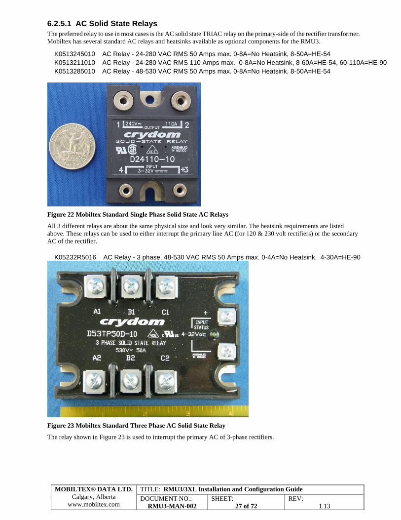
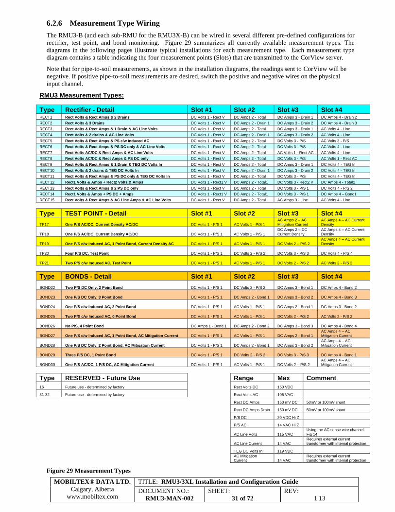
6.2.6 Measurement Type Wiring
The RMU3-B (and each sub-RMU for the RMU3X-B) can be wired in several different pre-defined configurations for
rectifier, test point, and bond monitoring. Figure 29 summarizes all currently available measurement types. The
diagrams in the following pages illustrate typical installations for each measurement type. Each measurement type
diagram contains a table indicating the four measurement points (Slots) that are transmitted to the CorView server.
Note that for pipe-to-soil measurements, as shown in the installation diagrams, the readings sent to CorView will be
negative. If positive pipe-to-soil measurements are desired, switch the positive and negative wires on the physical
input channel.
RMU3 Measurement Types:
Type Rectifier - Detail Slot #1 Slot #2 Slot #3 Slot #4 RECT1 Rect Volts & Rect Amps & 2 Drains DC Volts 1 - Rect V DC Amps 2 - Total DC Amps 3 - Drain 1 DC Amps 4 - Drain 2
RECT2 Rect Volts & 3 Drains DC Volts 1 - Rect V DC Amps 2 - Drain 1 DC Amps 3 - Drain 2 DC Amps 4 - Drain 3
RECT3 Rect Volts & Rect Amps & 1 Drain & AC Line Volts DC Volts 1 - Rect V DC Amps 2 - Total DC Amps 3 - Drain 1 AC Volts 4 - Line
RECT4 Rect Volts & 2 drains & AC Line Volts DC Volts 1 - Rect V DC Amps 2 - Drain 1 DC Amps 3 - Drain 2 AC Volts 4 - Line
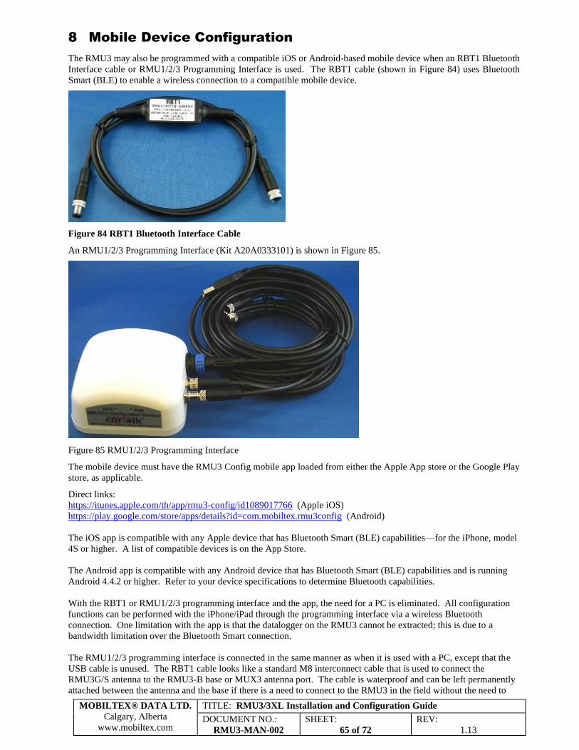
RECT5 Rect Volts & Rect Amps & PS c/w induced AC DC Volts 1 - Rect V DC Amps 2 - Total DC Volts 3 - P/S AC Volts 3 - P/S
RECT6 Rect Volts & Rect Amps & PS DC only & AC Line Volts DC Volts 1 - Rect V DC Amps 2 - Total DC Volts 3 - P/S AC Volts 4 - Line
RECT7 Rect Volts AC/DC & Rect Amps & AC Line Volts DC Volts 1 - Rect V DC Amps 2 - Total AC Volts 1 - Rect AC AC Volts 4 - Line
RECT8 Rect Volts AC/DC & Rect Amps & PS DC only DC Volts 1 - Rect V DC Amps 2 - Total DC Volts 3 - P/S AC Volts 1 - Rect AC
RECT9 Rect Volts & Rect Amps & 1 Drain & TEG DC Volts In DC Volts 1 - Rect V DC Amps 2 - Total DC Amps 3 - Drain 1 DC Volts 4 - TEG In
RECT10 Rect Volts & 2 drains & TEG DC Volts In DC Volts 1 - Rect V DC Amps 2 - Drain 1 DC Amps 3 - Drain 2 DC Volts 4 - TEG In
RECT11 Rect Volts & Rect Amps & PS DC only & TEG DC Volts In DC Volts 1 - Rect V DC Amps 2 - Total DC Volts 3 - P/S DC Volts 4 - TEG In
RECT12 Rect1 Volts & Amps + Rect2 Volts & Amps DC Volts 1 - Rect1 V DC Amps 2 - Total1 DC Volts 3 - Rect2 V DC Amps 4 - Total2
RECT13 Rect Volts & Rect Amps & 2 PS DC only DC Volts 1 - Rect V DC Amps 2 - Total DC Volts 3 - P/S 1 DC Volts 4 - P/S 2
RECT14 Rect1 Volts & Amps + PS DC + Amps DC Volts 1 - Rect1 V DC Amps 2 - Total1 DC Volts 3 - P/S 1 DC Amps 4 – Bond1
RECT15 Rect Volts & Rect Amps & AC Line Amps & AC Line Volts DC Volts 1 - Rect V DC Amps 2 - Total AC Amps 3 - Line AC Volts 4 - Line
Type TEST POINT - Detail Slot #1 Slot #2 Slot #3 Slot #4
TP17 One P/S AC/DC, Current Density AC/DC DC Volts 1 - P/S 1 AC Volts 1 - P/S 1 AC Amps 2 – AC Mitigation Current
AC Amps 4 – AC Current Density
TP18 One P/S AC/DC, Current Density AC/DC DC Volts 1 - P/S 1 AC Volts 1 - P/S 1 DC Amps 2 – DC Current Density
AC Amps 4 – AC Current Density
TP19 One P/S c/w Induced AC, 1 Point Bond, Current Density AC DC Volts 1 - P/S 1 AC Volts 1 - P/S 1 DC Volts 2 – P/S 2 AC Amps 4 – AC Current Density
TP20 Four P/S DC, Test Point DC Volts 1 - P/S 1 DC Volts 2 - P/S 2 DC Volts 3 - P/S 3 DC Volts 4 - P/S 4
TP21 Two P/S c/w Induced AC, Test Point DC Volts 1 - P/S 1 AC Volts 1 - P/S 1 DC Volts 2 - P/S 2 AC Volts 2 - P/S 2
BOND22 Two P/S DC Only, 2 Point Bond DC Volts 1 - P/S 1 DC Volts 2 - P/S 2 DC Amps 3 - Bond 1 DC Amps 4 - Bond 2
BOND23 One P/S DC Only, 3 Point Bond DC Volts 1 - P/S 1 DC Amps 2 - Bond 1 DC Amps 3 - Bond 2 DC Amps 4 - Bond 3
BOND24 One P/S c/w Induced AC, 2 Point Bond DC Volts 1 - P/S 1 AC Volts 1 - P/S 1 DC Amps 2 - Bond 1 DC Amps 3 - Bond 2
BOND25 Two P/S c/w Induced AC, 0 Point Bond DC Volts 1 - P/S 1 AC Volts 1 - P/S 1 DC Volts 2 - P/S 2 AC Volts 2 - P/S 2
BOND26 No P/S, 4 Point Bond DC Amps 1 - Bond 1 DC Amps 2 - Bond 2 DC Amps 3 - Bond 3 DC Amps 4 - Bond 4
BOND27 One P/S c/w Induced AC, 1 Point Bond, AC Mitigation Current DC Volts 1 - P/S 1 AC Volts 1 - P/S 1 DC Amps 2 - Bond 1 AC Amps 4 – AC Mitigation Current
BOND28 One P/S DC Only, 2 Point Bond, AC Mitigation Current DC Volts 1 - P/S 1 DC Amps 2 - Bond 1 DC Amps 3 - Bond 2 AC Amps 4 – AC Mitigation Current
BOND29 Three P/S DC, 1 Point Bond DC Volts 1 - P/S 1 DC Volts 2 - P/S 2 DC Volts 3 - P/S 3 DC Amps 4 - Bond 1
BOND30 One P/S AC/DC, 1 P/S DC, AC Mitigation Current DC Volts 1 - P/S 1 AC Volts 1 - P/S 1 DC Volts 2 – P/S 2 AC Amps 4 – AC Mitigation Current
Type RESERVED - Future Use Range Max Comment
16 Future use - determined by factory Rect Volts DC 150 VDC
31-32 Future use - determined by factory Rect Volts AC 105 VAC
Rect DC Amps 150 mV DC 50mV or 100mV shunt
Rect DC Amps Drain 150 mV DC 50mV or 100mV shunt
P/S DC 20 VDC Hi Z
P/S AC 14 VAC Hi Z
AC Line Volts 115 VAC Using the AC sense wire channel. Fig 14
AC Line Current 14 VAC Requires external current transformer with internal protection
TEG DC Volts In 119 VDC
AC Mitigation Current 14 VAC
Requires external current transformer with internal protection
Figure 29 Measurement Types
MOBILTEX® DATA LTD.
Calgary, Alberta
www.mobiltex.com
TITLE: RMU3/3XL Installation and Configuration Guide
DOCUMENT NO.:
RMU3-MAN-002
SHEET:
32 of 72
REV:
1.13
Notes:
-The RMU3 measurement inputs must not be directly connected to AC mains.
-AC Current transformers for AC Mitigation Current Measurement shall be of internal protection type.
6.2.6.1 Rectifier Measurement Type Diagrams
Cathodic
Protection
Rectifier
L1
L2
Earth
Ground
AC Line
Power
-
+
Current
Shunt
Resistor
Current
Shunt
Resistor
Voltmeter
Structure#1
Structure#2
RECT1DATA
SLOTDESCRIPTION
1 CH1 DCV RECTIFIER OUTPUT VOLTAGE
2
3
4
CH2 DCA RECTIFIER TOTAL CURRENT
CH3 DCA DRAIN #1 CURRENT
CH4 DCA DRAIN #2 CURRENT
Current
Shunt
Resistor
Current Meter
Anode
Groundbed
Figure 30 RECT1 Rectifier – Output Volts, Total Amps, and 2 Drains
Cathodic ProtectionRectifier
L1
L2
EarthGround
AC LinePower
-
+
CurrentShunt
Resistor
CurrentShunt
Resistor
Voltmeter
Structure#1
Structure#2
Structure#3
CurrentShunt
Resistor
RECT2DATASLOT
DESCRIPTION
1 CH1 DCV RECTIFIER OUTPUT VOLTAGE
2
3
4
CH2 DCA DRAIN #1 CURRENT
CH3 DCA DRAIN #2 CURRENT
CH4 DCA DRAIN #3 CURRENT
CurrentShunt
Resistor
Current Meter
AnodeGroundbed
MOBILTEX® DATA LTD.
Calgary, Alberta
www.mobiltex.com
TITLE: RMU3/3XL Installation and Configuration Guide
DOCUMENT NO.:
RMU3-MAN-002
SHEET:
33 of 72
REV:
1.13
Figure 31 RECT2 Rectifier – Output Volts and 3 Drains
Cathodic
Protection
Rectifier
L1
L2
Earth
Ground
AC Line
Power
-
+
Current
Shunt
Resistor
Current
Shunt
Resistor
Voltmeter
Structure#1
Structure#2
3:1
Attenuator
RECT3
DATA
SLOTDESCRIPTION
1 CH1 DCV RECTIFIER OUTPUT VOLTAGE
2
3
4
CH2 DCA RECTIFIER TOTAL CURRENT
CH3 DCA DRAIN #1 CURRENT
CH4 ACV RECTIFIER INPUT LINE VOLTAGE
Current
Shunt
Resistor
Current Meter
Anode
Groundbed
Figure 32 RECT3 Rectifier – Output Volts, Total Amps, Drain, and Input AC Volts
Cathodic
Protection
Rectifier
L1
L2
Earth
Ground
AC Line
Power
-
+
Current
Shunt
Resistor
Current
Shunt
Resistor
Voltmeter
Structure#1
Structure#2
3:1
Attenuator
RECT4
DATA
SLOTDESCRIPTION
1 CH1 DCV RECTIFIER OUTPUT VOLTAGE
2
3
4
CH2 DCA DRAIN #1 CURRENT
CH3 DCA DRAIN #2 CURRENT
CH4 ACV RECTIFIER INPUT LINE VOLTAGE
Current
Shunt
Resistor
Current Meter
Anode
Groundbed
MOBILTEX® DATA LTD.
Calgary, Alberta
www.mobiltex.com
TITLE: RMU3/3XL Installation and Configuration Guide
DOCUMENT NO.:
RMU3-MAN-002
SHEET:
34 of 72
REV:
1.13
Figure 33 RECT4 Rectifier - Output Volts, 2 Drains, and Input AC Volts
Cathodic
Protection
Rectifier
L1
L2
Earth
Ground
AC Line
Power
-
+
Voltmeter
Structure#1
Reference
Cell
RECT5
DATA
SLOTDESCRIPTION
1 CH1 DCV RECTIFIER OUTPUT VOLTAGE
2
3
4
CH2 DCA RECTIFIER TOTAL CURRENT
CH3 DCV PIPE-TO-SOIL VOLTAGE
CH3 ACV PIPE-TO-SOIL VOLTAGE
Current
Shunt
Resistor
Current Meter
Anode
Groundbed
Figure 34 RECT5 Rectifier – Output Volts, Total Current, and Pipe-To-Soil AC/DC
Cathodic
Protection
Rectifier
L1
L2
Earth
Ground
AC Line
Power
-
+
Voltmeter
Structure#1
3:1
Attenuator
Reference
Cell
RECT6
DATA
SLOTDESCRIPTION
1 CH1 DCV RECTIFIER OUTPUT VOLTAGE
2
3
4
CH2 DCA RECTIFIER TOTAL CURRENT
CH3 DCV PIPE-TO-SOIL VOLTAGE
CH4 ACV RECTIFIER INPUT LINE VOLTAGE
Current
Shunt
Resistor
Current Meter
Anode
Groundbed
Figure 35 RECT6 Rectifier – Output Volts, Total Current, Pipe-To-Soil and Input AC Volts
MOBILTEX® DATA LTD.
Calgary, Alberta
www.mobiltex.com
TITLE: RMU3/3XL Installation and Configuration Guide
DOCUMENT NO.:
RMU3-MAN-002
SHEET:
35 of 72
REV:
1.13
Cathodic
Protection
Rectifier
L1
L2
Earth
Ground
AC Line
Power
-
+
Voltmeter
Structure#1
3:1
Attenuator
RECT7
DATA
SLOTDESCRIPTION
1 CH1 DCV RECTIFIER OUTPUT VOLTAGE
2
3
4
CH2 DCA RECTIFIER TOTAL CURRENT
CH1 ACV RECTIFIER OUTPUT VOLTAGE
CH4 ACV RECTIFIER INPUT LINE VOLTAGE
Current
Shunt
Resistor
Current Meter
Anode
Groundbed
Figure 36 RECT7 Rectifier – Output Volts AC/DC, Total Current, and Input AC Volts
Cathodic
Protection
Rectifier
L1
L2
Earth
Ground
AC Line
Power
-
+
Voltmeter
Structure#1
Reference
Cell
RECT8DATA
SLOTDESCRIPTION
1 CH1 DCV RECTIFIER OUTPUT VOLTAGE
2
3
4
CH2 DCA RECTIFIER TOTAL CURRENT
CH3 DCV PIPE-TO-SOIL VOLTAGE
CH1 ACV RECTIFIER OUTPUT VOLTAGE
Current
Shunt
Resistor
Current Meter
Anode
Groundbed
Figure 37 RECT8 Rectifier – Output Volts AC/DC, Total Current, and Pipe-To-Soil
MOBILTEX® DATA LTD.
Calgary, Alberta
www.mobiltex.com
TITLE: RMU3/3XL Installation and Configuration Guide
DOCUMENT NO.:
RMU3-MAN-002
SHEET:
36 of 72
REV:
1.13
Cathodic
Protection
Rectifier
+
-
Earth
Ground
-
+
Current
Shunt
Resistor
Current
Shunt
Resistor
Voltmeter
Structure#1
Structure#2
TEG
Source
Input
Power
RECT9DATA
SLOTDESCRIPTION
1 CH1 DCV RECTIFIER OUTPUT VOLTAGE
2
3
4
CH2 DCA RECTIFIER TOTAL CURRENT
CH3 DCA DRAIN #1 CURRENT
CH4 DCV RECTIFIER INPUT TEG VOLTAGE
Current
Shunt
Resistor
Current Meter
Anode
Groundbed
Figure 38 RECT9 TEG or Solar – Output Volts, Total Current, Drain, and Input DC Volts
Current
Shunt
Resistor
Current
Shunt
Resistor
Voltmeter
Structure#1
Structure#2
Cathodic
Protection
Rectifier
+
-
Earth
Ground
-
+
TEG
Source
Input
Power
RECT10DATA
SLOTDESCRIPTION
1 CH1 DCV RECTIFIER OUTPUT VOLTAGE
2
3
4
CH2 DCA DRAIN #1 CURRENT
CH3 DCA DRAIN #2 CURRENT
CH4 DCV RECTIFIER INPUT TEG VOLTAGE
Current
Shunt
Resistor
Current Meter
Anode
Groundbed
Figure 39 RECT10 TEG or Solar – Output Volts, 2 Drains, and Input DC Volts
MOBILTEX® DATA LTD.
Calgary, Alberta
www.mobiltex.com
TITLE: RMU3/3XL Installation and Configuration Guide
DOCUMENT NO.:
RMU3-MAN-002
SHEET:
37 of 72
REV:
1.13
Voltmeter
Structure#1
Reference
Cell
Cathodic
Protection
Rectifier
+
-
Earth
Ground
-
+
TEG
Source
Input
Power
RECT11
DATA
SLOTDESCRIPTION
1 CH1 DCV RECTIFIER OUTPUT VOLTAGE
2
3
4
CH2 DCA RECTIFIER TOTAL CURRENT
CH3 DCV PIPE-TO-SOIL VOLTAGE
CH4 DCV RECTIFIER INPUT TEG VOLTAGE
Current
Shunt
Resistor
Current Meter
Anode
Groundbed
Figure 40 RECT11 TEG or Solar – Output Volts, Total Current, Pipe-To-Soil, and Input DC Volt
Cathodic
Protection
Rectifier
L1
L2
Earth
Ground
AC Line
Power
-
+
Voltmeter
Anode
Groundbed
Structure#1
Cathodic
Protection
Rectifier
L1
L2
Earth
Ground
AC Line
Power
-
+
Voltmeter
Structure#2
RECT12DATA
SLOTDESCRIPTION
1 CH1 DCV RECTIFIER #1 OUTPUT VOLTAGE
2
3
4
CH2 DCA RECTIFIER #1 TOTAL CURRENT
CH3 DCV RECTIFIER #2 OUTPUT VOLTAGE
CH4 DCA RECTIFIER #2 TOTAL CURRENT
Current
Shunt
Resistor
Current Meter
Current
Shunt
Resistor
Current Meter
Anode
Groundbed
Figure 41 RECT12 Two Co-located Rectifiers – Rect #1/2 Output Volts, and Rect #1/2 Current
MOBILTEX® DATA LTD.
Calgary, Alberta
www.mobiltex.com
TITLE: RMU3/3XL Installation and Configuration Guide
DOCUMENT NO.:
RMU3-MAN-002
SHEET:
38 of 72
REV:
1.13
Cathodic
Protection
Rectifier
L1
L2
Earth
Ground
AC Line
Power
-
+
Voltmeter
Structure#1
Reference
Cell
RECT13
DATA
SLOTDESCRIPTION
1 CH1 DCV RECTIFIER OUTPUT VOLTAGE
2
3
4
CH2 DCA RECTIFIER TOTAL CURRENT
CH3 DCV PIPE-TO-SOIL #1 VOLTAGE
CH4 DCV PIPE-TO-SOIL #2 VOLTAGE
Current
Shunt
Resistor
Current Meter
Anode
Groundbed
Structure#2
Figure 42 RECT13 Rectifier – Output Volts, Total Current, and 2 Pipe-To-Soil DC
Cathodic ProtectionRectifier
L1
L2
EarthGround
AC LinePower
-
+
Voltmeter
ProctectedStructure#1
ReferenceCell
RECT14DATASLOT
DESCRIPTION
1 CH1 DCV RECTIFIER OUTPUT VOLTAGE
2
3
4
CH2 DCA RECTIFIER TOTAL CURRENT
CH3 DCV PIPE-TO-SOIL #1 VOLTAGE
CH4 DCA BOND #1 CURRENT
CurrentShunt
Resistor
Current Meter
AnodeGroundbed
ForeignStructure#2
CurrentShunt
ResistorBond
Figure 43 RECT14 Rectifier – Output Volts, Total Current, 1 Pipe-To-Soil DC, and 1 Bond Current DC
MOBILTEX® DATA LTD.
Calgary, Alberta
www.mobiltex.com
TITLE: RMU3/3XL Installation and Configuration Guide
DOCUMENT NO.:
RMU3-MAN-002
SHEET:
39 of 72
REV:
1.13
Cathodic ProtectionRectifier
L1
L2
EarthGround
AC LinePower
-
+
Voltmeter
Structure
3:1Attenuator
RECT15DATASLOT
DESCRIPTION
1 CH1 DCV RECTIFIER OUTPUT VOLTAGE
2
3
4
CH2 DCA RECTIFIER TOTAL CURRENT
CH3 ACA RECTIFIER INPUT LINE CURRENT
CH4 ACV RECTIFIER INPUT LINE VOLTAGE
CurrentShunt
Resistor
Current Meter
AnodeGroundbed
AC Current Transformer
Figure 44 RECT15 Rectifier – Output Volts, Total Current, Input AC Amps and Input AC Volts
6.2.6.2 Test Point Measurement Type Diagrams
TP17
DATASLOT
DESCRIPTION
1 CH1 DCV PIPE-TO-SOIL VOLTAGE
2
3
4
CH1 ACV PIPE-TO-SOIL VOLTAGE
CH2 ACA AC MITIGATION CURRENT
CH4 ACA AC CURRENT DENSITY
Structure
ReferenceCell
Coupon
Ground DecouplingDevice
AC Current Transformer
AC Current Transformer
LCT1A
Figure 45 TP17 Testpoint – Pipe-To-Soil DC/AC, AC Mitigation Current, and AC Current Density
MOBILTEX® DATA LTD.
Calgary, Alberta
www.mobiltex.com
TITLE: RMU3/3XL Installation and Configuration Guide
DOCUMENT NO.:
RMU3-MAN-002
SHEET:
40 of 72
REV:
1.13
Structure
ReferenceCell
Foreign Structure
TP18
DATASLOT
DESCRIPTION
1 CH1 DCV PIPE-TO-SOIL VOLTAGE
2
3
4
CH1 ACV PIPE-TO-SOIL VOLTAGE
CH2 DCA DC CURRENT DENSITY
CH4 ACA AC CURRENT DENSITY
AC Current Transformer
CurrentShunt
Resistor
Figure 46 TP18 Testpoint – Pipe-To-Soil DC/AC, DC Current Density, and AC Current Density
Structure
ReferenceCell
Foreign Structure #1
TP19
DATASLOT
DESCRIPTION
1 CH1 DCV PIPE-TO-SOIL #1 VOLTAGE
2
3
4
CH1 ACV PIPE-TO-SOIL #1 VOLTAGE
CH2 DCV PIPE-TO-SOIL #2 VOLTAGE
CH4 ACA AC CURRENT DENSITY
AC Current Transformer
Foreign Structure #2
Figure 47 TP19 Testpoint – Pipe-To-Soil 1 DC/AC, Pipe-To-Soil 2 DC, and AC Current Density
MOBILTEX® DATA LTD.
Calgary, Alberta
www.mobiltex.com
TITLE: RMU3/3XL Installation and Configuration Guide
DOCUMENT NO.:
RMU3-MAN-002
SHEET:
41 of 72
REV:
1.13
Structure#1Reference
CellStructure#2
TP20
DATA
SLOTDESCRIPTION
1 CH1 DCV PIPE-TO-SOIL #1 VOLTAGE
2
3
4
CH2 DCV PIPE-TO-SOIL #2 VOLTAGE
CH3 DCV PIPE-TO-SOIL #3 VOLTAGE
CH4 DCV PIPE-TO-SOIL #4 VOLTAGE
Structure#3 Structure#4
Figure 48 TP20 Testpoint – 4 Pipe-To-Soil DC
Structure#1Reference
CellStructure#2
TP21DATA
SLOTDESCRIPTION
1 CH1 DCV PIPE-TO-SOIL #1 VOLTAGE
2
3
4
CH1 ACV PIPE-TO-SOIL #1 VOLTAGE
CH2 DCV PIPE-TO-SOIL #2 VOLTAGE
CH2 ACV PIPE-TO-SOIL #2 VOLTAGE
Figure 49 TP21 Testpoint – 2 Pipe-To-Soil AC/DC
MOBILTEX® DATA LTD.
Calgary, Alberta
www.mobiltex.com
TITLE: RMU3/3XL Installation and Configuration Guide
DOCUMENT NO.:
RMU3-MAN-002
SHEET:
42 of 72
REV:
1.13
6.2.6.3 Bond Measurement Type Diagrams
Protected
Structure#1
Reference
Cell
Foreign
Structure#2
Foreign
Structure#3
Bond
Bond
Current
Shunt
Resistor
Current
Shunt
Resistor
BOND22
DATA
SLOTDESCRIPTION
1 CH1 DCV PIPE-TO-SOIL #1 VOLTAGE
2
3
4
CH2 DCV PIPE-TO-SOIL #2 VOLTAGE
CH3 DCA BOND #1 CURRENT
CH4 DCA BOND #2 CURRENT
Figure 50 BOND22 Bond – 2 Pipe-To-Soil, and 2 Bond Currents
Protected
Structure#1
Reference
Cell
Foreign
Structure#2
Foreign
Structure#3
Bond
Bond
Current
Shunt
Resistor
Current
Shunt
Resistor
Foreign
Structure#4Bond Current
Shunt
Resistor
BOND23DATA
SLOTDESCRIPTION
1 CH1 DCV PIPE-TO-SOIL VOLTAGE
2
3
4
CH2 DCA BOND #1 CURRENT
CH3 DCA BOND #2 CURRENT
CH4 DCA BOND #3 CURRENT
Figure 51 BOND23 Bond – Pipe-To-Soil, and 3 Bond Currents
MOBILTEX® DATA LTD.
Calgary, Alberta
www.mobiltex.com
TITLE: RMU3/3XL Installation and Configuration Guide
DOCUMENT NO.:
RMU3-MAN-002
SHEET:
43 of 72
REV:
1.13
Protected
Structure#1
Reference
Cell
Foreign
Structure#2
Foreign
Structure#3
Bond
Bond
Current
Shunt
Resistor
Current
Shunt
Resistor
BOND24
DATA
SLOTDESCRIPTION
1 CH1 DCV PIPE-TO-SOIL VOLTAGE
2
3
4
CH1 ACV PIPE-TO-SOIL VOLTAGE
CH2 DCA BOND #1 CURRENT
CH3 DCA BOND #2 CURRENT
Figure 52 BOND24 Bond – Pipe-To-Soil AC/DC, and 2 Bond Currents
Protected
Structure#1
Reference
Cell
Foreign
Structure#2
Foreign
Structure#3
Bond
Bond
Current
Shunt
Resistor
Current
Shunt
Resistor
BOND25
DATA
SLOTDESCRIPTION
1 CH1 DCV PIPE-TO-SOIL #1 VOLTAGE
2
3
4
CH1 ACV PIPE-TO-SOIL #1 VOLTAGE
CH2 DCV PIPE-TO-SOIL #2 VOLTAGE
CH2 ACV PIPE-TO-SOIL #2 VOLTAGE
Figure 53 BOND25 Bond – 2 Pipe-To-Soil AC/DC
MOBILTEX® DATA LTD.
Calgary, Alberta
www.mobiltex.com
TITLE: RMU3/3XL Installation and Configuration Guide
DOCUMENT NO.:
RMU3-MAN-002
SHEET:
44 of 72
REV:
1.13
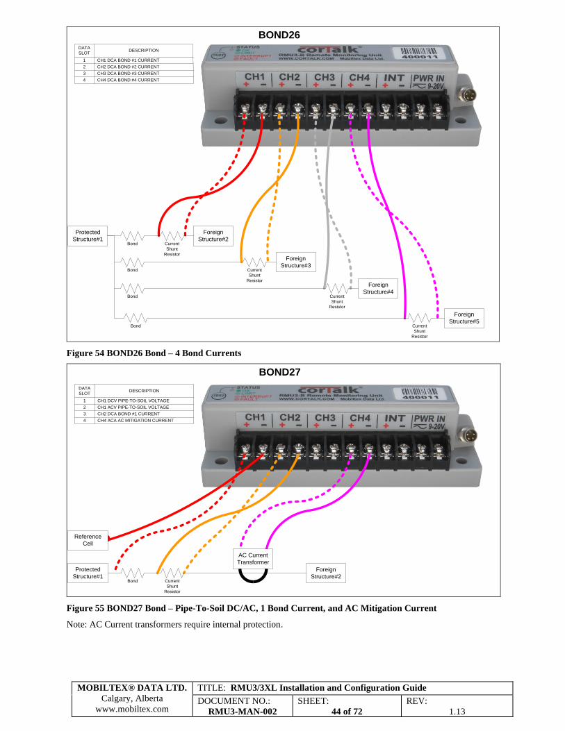
Protected
Structure#1
Foreign
Structure#2
Foreign
Structure#3
Bond
Bond
Current
Shunt
Resistor
Current
Shunt
ResistorForeign
Structure#4Bond Current
Shunt
Resistor
Foreign
Structure#5Bond Current
Shunt
Resistor
BOND26DATA
SLOTDESCRIPTION
1 CH1 DCA BOND #1 CURRENT
2
3
4
CH2 DCA BOND #2 CURRENT
CH3 DCA BOND #3 CURRENT
CH4 DCA BOND #4 CURRENT
Figure 54 BOND26 Bond – 4 Bond Currents
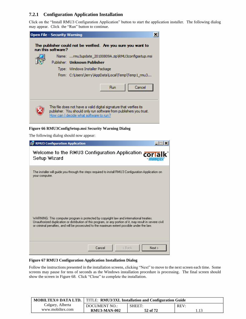
Protected
Structure#1
Reference
Cell
Foreign
Structure#2Bond Current
Shunt
Resistor
BOND27
DATA
SLOTDESCRIPTION
1 CH1 DCV PIPE-TO-SOIL VOLTAGE
2
3
4
CH1 ACV PIPE-TO-SOIL VOLTAGE
CH2 DCA BOND #1 CURRENT
CH4 ACA AC MITIGATION CURRENT
AC Current
Transformer
Figure 55 BOND27 Bond – Pipe-To-Soil DC/AC, 1 Bond Current, and AC Mitigation Current
Note: AC Current transformers require internal protection.
MOBILTEX® DATA LTD.
Calgary, Alberta
www.mobiltex.com
TITLE: RMU3/3XL Installation and Configuration Guide
DOCUMENT NO.:
RMU3-MAN-002
SHEET:
45 of 72
REV:
1.13
Protected
Structure#1
Reference
Cell
Foreign
Structure#2
Foreign
Structure#3
Bond
Bond
Current
Shunt
Resistor
Current
Shunt
Resistor
BOND28
DATA
SLOTDESCRIPTION
1 CH1 DCV PIPE-TO-SOIL VOLTAGE
2
3
4
CH2 DCA BOND #1 CURRENT
CH3 DCA BOND #2 CURRENT
CH4 ACA AC MITIGATION CURRENT
AC Current
Transformer
Figure 56 BOND28 Bond – Pipe-To-Soil DC, 2 Bond Currents, and AC Mitigation Current
Note: AC current transformers require internal protection.
Protected
Structure#1
Foreign
Structure#2
Foreign
Structure#3Bond
BOND29
DATA
SLOTDESCRIPTION
1 CH1 DCV PIPE-TO-SOIL #1 VOLTAGE
2
3
4
CH2 DCV PIPE-TO-SOIL #2 VOLTAGE
CH3 DCV PIPE-TO-SOIL #3 VOLTAGE
CH4 DCA BOND #1 CURRENT
Reference
Cell
Current
Shunt
Resistor
Bond
Figure 57 BOND29 Bond – Three Pipe-To-Soil DC, 1 Bond Current
MOBILTEX® DATA LTD.
Calgary, Alberta
www.mobiltex.com
TITLE: RMU3/3XL Installation and Configuration Guide
DOCUMENT NO.:
RMU3-MAN-002
SHEET:
46 of 72
REV:
1.13
ProtectedStructure#1
ReferenceCell
ForeignStructure#2
Bond/AC Mitigation System
BOND30
DATASLOT
DESCRIPTION
1 CH1 DCV PIPE-TO-SOIL 1 VOLTAGE
2
3
4
CH1 ACV PIPE-TO-SOIL 1 VOLTAGE
CH2 DCV PIPE-TO-SOIL 2 VOLTAGE
CH4 ACA AC MITIGATION CURRENT
AC Current Transformer
Figure 58 BOND30 Bond – Pipe-To-Soil 1 DC/AC, Pipe-To-Soil 2 DC, and AC Mitigation Current
6.2.6.4 Field Installable User Label Set (RMU3-B only)
The standard RMU3 kit includes a “Field Installable User Label Set” that contains pre-printed labels for the different
measurement configuration types. The installer can optionally apply the proper label to either the bottom or top of the
terminal block on the RMU3-B to indicate actual wiring connections associated with that specific measurement type.
The red number located at the bottom-center of each label indicates the actual measurement type.
Figure 59 Field Installable User Label Set
MOBILTEX® DATA LTD.
Calgary, Alberta
www.mobiltex.com
TITLE: RMU3/3XL Installation and Configuration Guide
DOCUMENT NO.:
RMU3-MAN-002
SHEET:
47 of 72
REV:
1.13
Figure 60 Example of Label on Bottom of Terminal Block
Figure 61 Example of Label on Top of Terminal Block
6.2.6.5 Measurement Wiring Connections
The programmed “Measurement Type” will determine the signals monitored and the associated wiring connection
requirements. Wire the appropriate measurement signals from the rectifier, test point or bond to the terminal block on
the RMU3-B. In most applications, it is convenient to parallel tap the analog signals from the existing rectifier meters.
Unused analog input channels should be disabled using the RMU3 configuration software or alternatively, a shorting
wire should be installed between the two terminals of the unused channel.
An optional wiring kit (A20103RMU30), containing a variety of crimp terminals, wiring, cable ties and cable tie mounts,
is available. Electrical connections to the RMU3-B or RMU3X-B can be made using either direct wire connections (22
to 14 AWG wire size) or crimped spade lug terminal connectors (0.275” or 7mm maximum spade lug width). Lightning
immunity is enhanced by utilizing 600 volt, 105C rated wiring (as supplied with the optional wiring kit) which has a
thicker insulation system and higher voltage breakdown rating as compared to more common 300 volt rated wiring
systems. In the case of the RMU3X-B, the terminal block for each sub-RMU bank is pluggable and removable to allow
easy replacement of the RMU3X-B without having to remove all of the wiring from the screw terminals.
6.3 Interconnection Cable
Route the previously installed interconnection cable from the RMU3-G/S to the RMU3-B/RMU3X-B. For maximum
lightning immunity this cable should be physically routed away from other wiring, especially AC line level connections.
MOBILTEX® DATA LTD.
Calgary, Alberta
www.mobiltex.com
TITLE: RMU3/3XL Installation and Configuration Guide
DOCUMENT NO.:
RMU3-MAN-002
SHEET:
48 of 72
REV:
1.13
The un-terminated M8-style female connector going to the RMU3-B should remain disconnected until the RMU3 has
been configured. The interconnect cable may be extended up to a maximum length of 24 meters (78 feet) by screwing
together extension cables.
Note that an installation that uses the MUX3 multiplexer has additional limitations on cable lengths. Refer to section
6.2.2.
6.4 Startup and Verification
Once the rectifier, test point, or bond is wired according to one of the diagrams, the measurement type, current shunt
scaling factors (if used), and alarm limits (if used) should be programmed into the RMU3 using the RMU3 configuration
software tool, (see section 7).
All wiring should be secured and inspected before the RMU3-G/S and RMU3-B/RMU3X-B are connected together.
The RMU3 will start operation when the interconnection cable coming from the RMU3-G/S is connected to the M8-
style connector on the RMU3-B/RMU3X-B or MUX3 antenna port.
After the interconnect cable is attached between the RMU3-B or MUX3 and the RMU3-G/S transmitter, observe the
RMU3-B “Status” LED indicator (refer to section 6.5 for detailed LED operation descriptions). Transmissions from
RMU3-G/S field devices typically require from about 1 to 2 minutes (5 minutes maximum) to arrive at CorView.
After inspecting the installation, re-apply power to the rectifier and verify proper rectifier operation.
Once the rectifier is operating, press the “Test” button on the RMU3-B/RMU3X-B to initiate an immediate measurement
cycle and “Button Press” exception transmission to the CorView web host.
If the installation utilizes the door switch function, then the rectifier door should be closed to verify operation. Wait a
minimum of 2 minutes after closing the door to allow the measurement and “door closed” transmission to occur. Note
that a maximum of 6 door switch or “Test” button transmissions are allowed during a 6-hour period.
The actual measurement readings from the site should appear on CorView shortly after the message was transmitted.
CorView can be configured to automatically send emails containing the measurement readings to an individual or group
of email users. Because these emails are short and wireless-friendly, many clients send the readings directly to their
field installers wireless email device(s) for near immediate end-to-end operation confirmation and verification of
measurement values. Alternatively, the measurement readings can be locally retrieved and displayed using the
RMU3PGM configuration tool or the RBT1 Bluetooth interface. It is good practice to confirm that all the measurements
are as expected and that they are not too close to any programmed alarm limits (if utilized).
The installation and site should be inspected a final time before properly securing the equipment and leaving the site.
6.5 Status LED
The RMU3-B/RMU3X-B has a dual color “Status” LED (see Figure 62) that provides status information to the user.
The LED functions as follows:
• Green LED Operation: If the battery voltage is OK, Power In voltage sense is present or not enabled, and readings
are within the configured limits, the green LED turns on when the RMU3-B has supply voltage from the Class 2
source. If Power In voltage sense is enabled and there is no voltage sense signal, the green LED will not illuminate.
If limits are enabled and there is a reading that is outside the limits, the green LED will flash at a rate of 100ms on,
100ms off. If a CorView host acknowledgement has not yet been received, the green LED will flash at a rate of
250ms on, 250ms off. After the CorView host acknowledgement has been successfully received the green LED
will be on at a steady state condition or flashing rapidly to indicate a limits violation.
• Fault: The red LED will blink with a cadence of 500ms on, 500ms off. The flashing will start as soon as the fault
is detected. Specific fault information may then be retrieved and reset from the RMU3-B using the configuration
tool.
• Exception limit exceeded: The red LED will blink with a cadence of 250 ms on, 250 ms off. The flashing will start
immediately after the test button is pressed, or the door switch state is changed. The RMU3 will allow a maximum
of 6 exception messages in a 6 hour period. If this limit is exceeded, test button and door switch exceptions are
ignored until the next 6 hour period starts. For every 6 hour period after the limit is exceeded, the exception counter
decrements by 1.
• Interruption: The red LED will blink at the cadence of the interruption signal. When the red LED is on, current
from the rectifier is being interrupted.
MOBILTEX® DATA LTD.
Calgary, Alberta
www.mobiltex.com
TITLE: RMU3/3XL Installation and Configuration Guide
DOCUMENT NO.:
RMU3-MAN-002
SHEET:
49 of 72
REV:
1.13
RMU3-B RMU3X-B
Figure 62 RMU3 LED Status Indicator
MOBILTEX® DATA LTD.
Calgary, Alberta
www.mobiltex.com
TITLE: RMU3/3XL Installation and Configuration Guide
DOCUMENT NO.:
RMU3-MAN-002
SHEET:
50 of 72
REV:
1.13
7 PC Configuration
7.1 Configuration Equipment Requirements
The following items will be needed when configuring an RMU3 with a PC.
1. RMU1/2/3 Configuration Interface (Kit A20A0333101) (Optional with RMU3X-B)
The configuration interface is housed in a plastic enclosure (see Figure 63). It has three cables exiting from the
enclosure: a USB cable that attaches to a PC, an M8 (round 4-pin connector) female cable that attaches to the
RMU3-B/RMU3X-B base unit or MUX3 antenna port, and an M8 male cable that attaches to the RMU3-G/S
antenna unit. All cables are field replaceable.
The interface is powered from the PC USB port, so an external power supply in not required.
The configuration interface has a strong magnet located on the bottom of the case (see Figure 64) that allows
the configuration interface to be temporarily attached to a ferrous surface. The magnet is covered by a non-
marring label to prevent damage to the surface to which it is being attached.
Two LED indicators on the side of the configuration interface show the current state of the device. The green
PWR LED lights up when power is being delivered to the RMU3 device that is being programmed. The red
DATA LED flashes when information is transferred over the USB connection to the PC.
2. USB A to USB mini-B cable (W160DJ06USB) (Optional for RMU3X-B, not used with RMU3-B)
With an RMU3X-B base, it is possible to program the RMU3 without the RMU3 Configuration Interface.
Instead, a standard USB A to USB mini-B cable may be attached between the PC and the USB port on the
RMU3X-B. The RMU3X-B base acts as the programming interface in this case. When programming the
RMU3, power must be supplied to the PWRIN terminals on the RMU3X-B. If the USB A to USB mini-B
cable is used, then the RMU3 Configuration Interface must not be connected at the same time.
3. Programming Application and Driver USB Drive Stick
To use the configuration interface, you will require the USB drive stick that shipped with the configuration
interface box. The USB drive contains drivers and an application for the RMU3 configuration interface. If
you do not have the USB drive, the contents can be downloaded from the Mobiltex support site. Contact your
Mobiltex representative for download instructions.
4. Personal Computer (PC)
The application software and drivers require that the PC be running Windows XP SP2 or higher for an operating
system. The PC must have an available USB port.
Figure 63 RMU1/2/3 Configuration Interface
MOBILTEX® DATA LTD.
Calgary, Alberta
www.mobiltex.com
TITLE: RMU3/3XL Installation and Configuration Guide