379
Hardware-Description Oktober RO-INTERFACE-ETH 2010

Hardware-Description
Oktober
RO-INTERFACE-ETH
2010

INDEX
Index | 2Seite
1. Introduction 5
1.1. General remarks 5
1.2. Customer satisfaction 5
1.3. Customer response 5
2. Hardware description 7
2.1. Overview screen 7
2.2. Technical data 8
2.3. Plug-in connector of the module 9
92.3.1. Power supply 92.3.2. Ethernet interface
2.4. Buttons of the module 10
2.5. Controll LEDs 11
112.5.1. Definition of LEDs
3. Configuring the module 13
3.1. Configuration via DELIB Configuration utility 13
3.2. Configuration via internal web server 17
3.3. Factory settings 18
4. Firmware Update 20
4.1. DEDITEC Flasher 20
4.2. Web interface 21
5. Restore basic configuration 24
5.1. Restore IP address 24

INDEX
Index | 3Seite
5.2. Restore firmware 24
6. Software 26
6.1. Using our products 26
266.1.1. Access via graphical applications 266.1.2. Access via the DELIB driver library 266.1.3. Access via protocol 276.1.4. Access via provided test programs
6.2. DELIB driver library 28
286.2.1. Overview 306.2.2. Supported operating systems 306.2.3. Supported programming languages 316.2.4. Installation DELIB driver library 336.2.5. DELIB Configuration Utility
6.3. Test programs 34
346.3.1. Digital Input-Output Demo 356.3.2. Analog Input-Output Demo 366.3.3. Stepper Demo
7. Appendix 38
7.1. Revisions 38
7.2. Copyrights and trademarks 39

I
Introduction | Seite 4
Introduction

Introduction | Seite 5
1. Introduction
1.1. General remarks
First of all, we would like to congratulate you to the purchase of a high qualityDEDITEC product.
Our products are being developed by our engineers according to qualityrequirements of high standard. Already during design and development we takecare that our products have -besides quality- a long availability and an optimalflexibility.
Modular design
The modular design of our products reduces the time and the cost ofdevelopment. Therefor we can offer you high quality products at a competitiveprice.
Availability
Because of the modular design of our products, we have to redesign only amodule instead of the whole product, in case a specific component is no longeravailable.
1.2. Customer satisfaction
Our philosophy: a content customer will come again. Therefor customersatisfaction is in first place for us.
If by any chance, you are not content with the performance of our product,please contact us by phone or mail immediately.
We take care of the problem.
1.3. Customer response
Our best products are co-developments together with our customers. Thereforwe are thankful for comments and suggestions.

II
Hardware description | Seite 6
Hardware description

Hardware description | Seite 7
2. Hardware description
2.1. Overview screen
The figure shows the control module with ethernet interface (left side) combinedwith an input/output module (right side).
The figure shows the control module with ethernet interface (left side) combinedwith a flexible connector input/output module (right side).

Hardware description | Seite 8
2.2. Technical data
Single power supply +7V..+24V DC
10/100 Mbit/sec Ethernet interface
Input/output access over TCP/IP
WEB interface
Configuration over web interface
9 Control LEDs
RJ45 Socket
Timeout feature providing ability to disconnect outputs for safety reasons
Expandable in 16 gradations
Can be combined without any problem to other modules of the RO series
Windows driver library DELIB

Hardware description | Seite 9
2.3. Plug-in connector of the module
2.3.1. Power supply
The input-power-supply-range lies between +7V and +24V DC.The powersupply can be realized with a standard AC/DC adaptor with 1A output current. Asuitable plug-in connector is delivered.
2.3.2. Ethernet interface
The network connection is provided by a RJ45 socket.
LED Description
1 Activity
2 10/100 Mbit

Hardware description | Seite 10
2.4. Buttons of the module
Left Button:
Reset IP address to default
(see chapter 5.1)
Right Button:
Reset firmware to factory settings.
(see chapter 5.2)

Hardware description | Seite 11
2.5. Controll LEDs
The Ethernet module has a series of control LEDs. They are used for easy visualindication of various state functions.
While switching the module on, in normal operating mode, the module shouldsignalize the following sequence:
approx. 20 sec after switching the module on, LED 1 and 2 are flashing briefly.-> Operating system has been loaded successfully.
Then LED 3 is on permanently and LED 1 is flashing. -> Module is ready.
2.5.1. Definition of LEDs
LED Label Description
above 3,3V Internal 3,3V power supply
above 5V Internal 5V power supply
1 CPU Activity 2x flashing + long break. Operating system reports:Status OK
2 InterfaceActivity
Active communication over Ethernet
3 Status LED is on -> Module is ready
4 ERROR Error during ethernet-transfer (for details see document”Serial protocol”)
5 Inputs:Change
"State change" between 2 read-out cycles detected
6 Outputs: Auto-Off
Due to timeout, all outputs are switched-off for safetyreasons
7 I/O Access CPU-access to the connected I/O modules.

III
Configuring the module | Seite 12
Configuring the module

Configuring the module | Seite 13
3. Configuring the module
3.1. Configuration via DELIB Configuration utility
This method allows a simple configuration of the product. Following basicvalues can be changed.
Module name
IP address
Net mask
Default gateway
DNS server
Additionally with this tool all DEDITEC ethernet devices in the LAN network aredisplayed.
The following pages describe how it works...

Configuring the module | Seite 14
Start DELIB Configuration utility as follows:
Start -> Programs -> DEDITEC -> DELIB -> DELIB Configuration Utility
1. Module Selection: select RO-ETH
2. Find and configure RO-ETH Module

Configuring the module | Seite 15
1. Scan RO-ETH modules: So you can find all DEDITEC ETH modules on localethernet stream. Therefore we use an ethernet protocol which will not berouted. Because of that you can configure only modules which are connectedto the bus. The advantage of this method is, that you can find modules whichare not in the same sub net, of which you are configuring.
2. Click on the module, which you want to configure.

Configuring the module | Seite 16
Here you can change the module name according to your wishes
1. You can change module name, IP address, net mask, default gateway andDNS server.
2. Write new Values to Module.
Notice:
At the configuration of the RO-ETH module should be paid attention to the IPaddress. It has to be in the same IP segment in which the control PC is. Ofcourse you must not select an already used IP address.
If the standard IP address of the module is not from the address range of thenetwork, the module will not be reachable by TCP/IP at the moment. Problemsof accessibility will also occur, if the IP address is already used. However the IPaddress and the net mask of the ethernet module are configurable by this utility.Alternatively you can connect the module to the PC and set the IP address andthe net mask directly. After the accessibility is given, the further configuration isensued by a browser via the integrated web server of the ethernet module.
To these belongs ask your system administrator.

Configuring the module | Seite 17
3.2. Configuration via internal web server
The RO-ETH module has an own web server by which it can be configured, too.

Configuring the module | Seite 18
3.3. Factory settings
The factory settings of the ethernet module include following settings:
IP address: 192.168.1.1
The factory settings can be restored by pushing the left button -> see chapter5.2
IP address 192.168.1.1
Subnet mask 255.255.255.0
Standard gateway 192.168.1.254

IV
Firmware Update | Seite 19
Firmware Update

Firmware Update | Seite 20
4. Firmware Update
4.1. DEDITEC Flasher
Approach:
Download the latest firmware inclusive software update. http://www.deditec.de/en/module/software/delib/download.html
Extract all data to one folder
Start the application deditec-flasher.exe
1. Select the interface. For ethernet press the key "E"
2. Select the module which you want to update. Press the key "M" for CPUinterface
3. After successfully flashing , in the prompt appears: Flash OK!

Firmware Update | Seite 21
4.2. Web interface
Approach:
1. Type the IP address of your module in the browser

Firmware Update | Seite 22
1. Click on FW-Update
2. Select the file “ro_cpu_eth_fw.dfw”
3. Click on Firmware update

V
Restore basic configuration | Seite 23
Restore basic configuration

Restore basic configuration | Seite 24
5. Restore basic configuration
5.1. Restore IP address
The default value of the IP address is: 192.168.1.1
Left Button: Restore IP address to default (192.168.1.1):
To restore the IP address proceed as follow:
Push the button at least 5 sec.
After that, the left LEDs "CPU Activity" and "Interface Activity" should beflashing four times (confirmation of receipt)
After this, the module has following settings:
IP address 192.168.1.1
Subnet mask 255.255.255.0
Standard gateway 192.168.1.254
5.2. Restore firmware
To restore the firmware to default value proceed as follow:
Right Button: Restore firmware to factory settings
To restore the firmware to factory settings proceed as follow:
Press the button at least 10sec.
After this, the three LED‘s “CPU Activity”, “Interface Activity” and “Status”should be flashing four times (confirmation of receipt).
After this, the module restarts.
The firmware and configuration of the factory settings are now active again!

VI
Software | Seite 25
Software

Software | Seite 26
6. Software
6.1. Using our products
6.1.1. Access via graphical applications
We provide driverinterfaces e.g. for LabVIEW and ProfiLab. The DELIB driverlibrary is the basis, which can be directly activated by ProfiLAB.
For LabVIEW, we provide a simple driver connection with examples!
6.1.2. Access via the DELIB driver library
In the appendix, you can find the complete function reference for the integrationof our API-functions in your software. In addition we provide examples for thefollowing programming languages:
C
C++
C#
Delphi
VisualBasic
VB.NET
MS-Office
6.1.3. Access via protocol
The protocol for the activation of our products is open source. So you are ableto use our products on systems without Windows or Linux.

Software | Seite 27
6.1.4. Access via provided test programs
We provide simple handling test programs for the most important functions ofour products. These will be installed automatically by the installation of theDELIB driver library.
So you can test directly e.g. relays or you can check the voltage of an A/Dconverter.

Software | Seite 28
6.2. DELIB driver library
6.2.1. Overview
The following figure explains the structure of the DELIB driver library
The DELIB driver library allows an uniform response of DEDITEC hardware withparticular consideration of the following viewpoints:
Independent of operating system
Independent of programming language
Independent of the product
Program under diverse operating systems
The DELIB driver library allows an uniform response of our products on diverseoperating systems.
We has made sure, that all of our products can be responded by a fewcommands.Whatever which operating system you use. - Therefore the DELIB cares!

Software | Seite 29
Program with diverse programming languages
We provide uniform commands to create own applications. This will be solvedby the DELIB driver library.
You choose the programming language!
It can be simply developed applications under C++, C, Visual Basic, Delphi orLabVIEW®.
Program independent of the interface
Write your application independent of the interface !
Program an apllication for an USB product of us. - Also, it will work with anethernet or RS-232 product of us !
SDK-Kit for Programmer
Integrate the DELIB in your application. On demand you receive an installationscript for free, which allows you, to integrate the DELIB installation in yourapllication.

Software | Seite 30
6.2.2. Supported operating systems
Our products support the following operating systems:
Windows 2000
Windows XP
Windows Vista
Windows 7
Linux
6.2.3. Supported programming languages
Our products are responsive via the following programming languages:
C
C++
C#
Delphi
VisualBasic
VB.NET
MS-Office

Software | Seite 31
6.2.4. Installation DELIB driver library
DELIB stands for DEDITEC Library and contains the necessary libraries for themodules in the programming languages C, Delphi and Visual Basic.
Insert the DEDITEC driver CD into the drive and start „delib_install.exe“. The
DELIB driver library is also available on http://www.deditec.en/delib
Click on „Install“.

Software | Seite 32
The drivers will be installed.
The DELIB driver library is now installed. Press „Close“ to finish the installation.
You can configure your module with the „DELIB Configuration Utility“ (see
next chapter). This is only necessary, if more than one module is present.

Software | Seite 33
6.2.5. DELIB Configuration Utility
Start the “DELIB Configuration Utility” as follows:
Start Programs DEDITEC DELIB DELIB Configuration Utility.
The „DELIB Configuration Utility“ is a program to configure and subdivide
identical USB-modules in the system. This is only necessary if more than onemodule is present.

Software | Seite 34
6.3. Test programs
6.3.1. Digital Input-Output Demo
Start “Digital Input-Output Demo” as follows:
Start Programme DEDITEC DELIB Digital Input-Output Demo.
The screenshot shows a test of the RO-USB-O64-R64. The configuration of themodule (64 inputs and 64 outputs) is shown on the upper left side.

Software | Seite 35
6.3.2. Analog Input-Output Demo
Start “Analog Input-Output Demo” as follows:
Start Programme DEDITEC DELIB Analog Input-Output Demo.
The screenshot shows a test of the RO-USB-AD16-DA2_ISO. The configurationof the module (16 A/D inputs and 2 D/A outputs) is shown on the upper left side.

Software | Seite 36
6.3.3. Stepper Demo
Start “Stepper Demo” as follows:
Start Programme DEDITEC DELIB Stepper Demo.
The screenshot shows a test of the RO-USB-STEPPER2. The configuration ofthe module (2 Stepper) is shown on the upper left side.

VII
Appendix | Seite 37
Appendix

Appendix | Seite 38
7. Appendix
7.1. Revisions
Rev 1.00 First issue
Rev 2.00 Design change

Appendix | Seite 39
7.2. Copyrights and trademarks
Linux is registered trade-mark of Linus Torvalds.
Windows CE is registered trade-mark of Microsoft Corporation.
USB is registered trade-mark of USB Implementers Forum Inc.
LabVIEW is registered trade-mark of National Instruments.
Intel is registered trade-mark of Intel Corporation
AMD is registered trade-mark of Advanced Micro Devices, Inc.

Hardware-Description
Oktober
RO-DIGITAL-IN-OUT
2010

INDEX
Index | 2Seite
1. Introduction 6
1.1. General remarks 6
1.2. Customer satisfaction 6
1.3. Customer response 6
2. Hardware description 8
2.1. Opto-coupler inputs 9
92.1.1. Overview screen 102.1.2. Technical data 112.1.3. 16-bit counter 112.1.4. Registering short input pulses 112.1.5. Galvanically decouppled through optocouplers 122.1.6. Plug-in connector on the module 122.1.6.1. Connection wiring
132.1.6.2. Visual control of the inputs
132.1.6.3. Pinout
132.1.7. Variable input voltage range 142.1.7.1. Changing the input voltage
2.2. Relay outputs 15
152.2.1. Overview screen 162.2.2. Technical data 172.2.3. Timeout-protection 172.2.4. Plug-in connector on the module
17
2.2.4.1. Relay-outputs (galvanically decoupled, max.
1A)
182.2.4.2. Connection wiring
182.2.4.3. Visual control of the outputs
182.2.4.4. Pinout
2.3. MOSFET outputs 19
192.3.1. Overview screen 202.3.2. Technical data 212.3.3. Timeout-protection 212.3.4. Plug-in connector on the module

INDEX
Index | 3Seite
21
2.3.4.1. Optocoupler-outputs (galvanically isolated,
max. 2A DC)
222.3.4.2. Connection wiring
222.3.4.3. Pinout
3. Software 24
3.1. Using our products 24
243.1.1. Access via graphical applications 243.1.2. Access via the DELIB driver library 243.1.3. Access via protocol 253.1.4. Access via provided test programs
3.2. DELIB driver library 26
263.2.1. Overview 283.2.2. Supported operating systems 283.2.3. Supported programming languages 293.2.4. Installation DELIB driver library 313.2.5. DELIB Configuration Utility
3.3. Test programs 32
323.3.1. Digital Input-Output Demo
4. DELIB API reference 34
4.1. Management functions 34
344.1.1. DapiOpenModule 354.1.2. DapiCloseModule
4.2. Error handling 36
364.2.1. DapiGetLastError 374.2.2. DapiGetLastErrorText
4.3. Reading Digital inputs 38
384.3.1. DapiDIGet1 394.3.2. DapiDIGet8 404.3.3. DapiDIGet16 414.3.4. DapiDIGet32 424.3.5. DapiDIGet64 434.3.6. DapiDIGetFF32 444.3.7. DapiDIGetCounter

INDEX
Index | 4Seite
4.4. Setting Digital outputs 45
454.4.1. DapiDOSet1 464.4.2. DapiDOSet8 474.4.3. DapiDOSet16 484.4.4. DapiDOSet32 494.4.5. DapiDOSet64 504.4.6. DapiDOReadback32 514.4.7. DapiDOReadback64
4.5. Output timeout management 52
524.5.1. DapiSpecialCMDTimeout 534.5.2. DapiSpecialCMDTimeoutGetStatus
4.6. Test functions 54
544.6.1. DapiPing
4.7. Example program 55
5. Appendix 58
5.1. Revisions 58
5.2. Copyrights and trademarks 59

I
Introduction | Seite 5
Introduction

Introduction | Seite 6
1. Introduction
1.1. General remarks
First of all, we would like to congratulate you to the purchase of a high qualityDEDITEC product.
Our products are being developed by our engineers according to qualityrequirements of high standard. Already during design and development we takecare that our products have -besides quality- a long availability and an optimalflexibility.
Modular design
The modular design of our products reduces the time and the cost ofdevelopment. Therefor we can offer you high quality products at a competitiveprice.
Availability
Because of the modular design of our products, we have to redesign only amodule instead of the whole product, in case a specific component is no longeravailable.
1.2. Customer satisfaction
Our philosophy: a content customer will come again. Therefor customersatisfaction is in first place for us.
If by any chance, you are not content with the performance of our product,please contact us by phone or mail immediately.
We take care of the problem.
1.3. Customer response
Our best products are co-developments together with our customers. Thereforwe are thankful for comments and suggestions.
II
Hardware description | Seite 7
Hardware description

Hardware description | Seite 8
2. Hardware description
Using the in-/output modules is based on two 16 pol. connectors with each 8different current circuits. Each state of these (total 16) current circuits issignalized by a LED. The modules are numbered from left to right (see overviewscreen).

Hardware description | Seite 9
2.1. Opto-coupler inputs
2.1.1. Overview screen
The figure shows two modules next to each other with correspondingnumbering of the terminal blocks.
The lower figure shows a flexible conntector module with 32 outputs andcorresponding numbered ports. Each outer end of the module has a 26 pol. wiretrap connector. Thus, multiple modules can be connected in series using aribbon cable for each connection.

Hardware description | Seite 10
2.1.2. Technical data
Variable power supply min. 5V, max. 30V AC
16-bit counter for the first 16 input channels
Pulse-detection between 2 read out cycles, indicated by LED
LED status indication of the inputs
Galvanically isolated using optocouplers
Comfortable connector system with ejection mechanism
Expandable in 16 gradations
Can be combined without any problem to other modules of the RO series

Hardware description | Seite 11
2.1.3. 16-bit counter
The first 16 input channels have each a 16 bit counter. Thus, events as lightbarriers, turnstiles or push-buttons are counted. Easy logical circuits arerealizable, which may e.g. switch one or several outputs, if a counter reached acertain amount (set-point is reached). Please refer to the manual ”RO-series” toimplement such logical circuits into software.
2.1.4. Registering short input pulses
Short input pulses between to read-out cycles are registered through anadditional logic and can be separately read-out. A registered pulse on one ormore inputs is signalized by the LED ”Inputs: Change” on the control module.The LED is extinguishing, if the software-register of the input state change isread out by the user. For more indformation, see ”Register assignment”.
2.1.5. Galvanically decouppled through optocouplers
AC input optocouplers provide a galvanic isolation of the module towards theconnected equipment. They also provide a safe connection to the module forreverse currents and high voltage peaks.

Hardware description | Seite 12
2.1.6. Plug-in connector on the module
As terminal block, user-friendly terminal strips with locking protection andejection mechanism are used. They are reverse-polarity protected and allowquick replugging. The wire connection itself is realised with a screwlessconnector system. A tool is included with each module.
2.1.6.1. Connection wiring
Connecting the wires is to be effected at the ports with the same numbering, forexample: 1a & 1b, 2a & 2b. ...
The optocoupler inputs are suitable for AC voltage. Therefore it is not necessaryto take care of the connection polarity.
The figure shows two terminal blocks with numbered connection ports.

Hardware description | Seite 13
2.1.6.2. Visual control of the inputs
The state of each input is directly signalized by a separate LED. This simplifiesto detect and rectify wiring errors, because the signals on the cables are directlyobservable.
2.1.6.3. Pinout
Port Pin Port Pin
1 1a & 1b 9 9a & 9b
2 2a & 2b 10 10a & 10b
3 3a & 3b 11 11a & 11b
4 4a & 4b 12 12a & 12b
5 5a & 5b 13 13a & 13b
6 6a & 6b 14 14a & 14b
7 7a & 7b 15 15a & 15b
8 8a & 8b 16 16a & 16b
2.1.7. Variable input voltage range
The factory-default of the inputs is set to a voltage range of 15V to 30V. Thismay be changed to a range of 5V to 15V (even afterward).
Input voltage range 5V – 15V 15V – 30V
Resistance value 1K 2K2

Hardware description | Seite 14
2.1.7.1. Changing the input voltage
Each terminal block has 8 inputs sudivided in two groups and each group has itsown input voltage range (resulting groups: 1-4, 5-8, 9-12 und 13-16). Eachgroup‘s input voltage range is defined by a corresponding resistor network.
The following steps describes how to exchange one or more resistor networks.
Notice!
Bevore opening the device, please note the following:
Disconnect the power supply (unplug AC/DC adaptor)!
Do not touch electronic components. They could be destroyed by electrostaticdischarge! If necessary, touch grounded metal casings or radiators.
Remove a module‘s side element. Unscrew the three Phillips screws.
Pull the circuit board together with the front panel sideways out.
Lift the front panel from the module.
Every input module has two single rowed socket terminal strips in which theresistor networks are plugged in. Please carefully remove the desired resistornetwork and replace them it appropriate one.
Assembling the elements in done the reverse order.

Hardware description | Seite 15
2.2. Relay outputs
2.2.1. Overview screen
The figure shows two modules next to each other with correspondingnumbering of the terminal blocks.
The lower figure shows a flexible conntector module with 32 outputs andcorresponding numbered ports. Each outer end of the module has a 26 pol. wiretrap connector. Thus, multiple modules can be connected in series using aribbon cable for each connection.

Hardware description | Seite 16
2.2.2. Technical data
Timeout-protection
LED status indication of the outputs
Galvanically isolated using optocouplers
Comfortable connector system with ejection mechanism
Expandable in 16 gradations
Can be combined without any problem to other modules of the RO series
Max. switching voltage: 36V
Max. switching current: 1A
Max. switching power: 20W
Switching cycles according to the manufacturer: 10 Mio.
Hardware description | Seite 17
2.2.3. Timeout-protection
The timeout-protection gives the possibility to switch-off automatically theoutputs on its own to prevent damage. This takes place, if in a predefined timeframe no communication with the module was possible. Reasons could be cabledisruption, PC-crash and more. This way damage control, surcharge ofconnected equipment and risk of accidents can be avoided. Switching off theoutputs is indicated by a LED.
2.2.4. Plug-in connector on the module
As terminal block, user-friendly terminal strips with locking protection andejection mechanism are used. They are reverse-polarity protected and allowquick replugging. The wire connection itself is realised with a screwlessconnector system. A tool is included with each module.
2.2.4.1. Relay-outputs (galvanically decoupled, max. 1A)
The relays are able to switch voltages up to 36V. The max. current is 1A at amax. power of 20W.
Additionally, the relays provide a safe electrical isolation of the module to theconnected equipment.

Hardware description | Seite 18
2.2.4.2. Connection wiring
Connecting the wires is to be effected at the ports with the same numbering, forexample: 1a & 1b, 2a & 2b. ...
It is not necessary to take care to the correct polarity.
2.2.4.3. Visual control of the outputs
The state of each output is directly signalized by a separate LED. This simplifiesto detect and rectify wiring errors, because the signals on the cables are directlyobservable.
2.2.4.4. Pinout
Port Pin Port Pin
1 1a & 1b 9 9a & 9b
2 2a & 2b 10 10a & 10b
3 3a & 3b 11 11a & 11b
4 4a & 4b 12 12a & 12b
5 5a & 5b 13 13a & 13b
6 6a & 6b 14 14a & 14b
7 7a & 7b 15 15a & 15b
8 8a & 8b 16 16a & 16b

Hardware description | Seite 19
2.3. MOSFET outputs
2.3.1. Overview screen
The figure shows two modules next to each other with correspondingnumbering of the terminal blocks.
The lower figure shows a flexible conntector module with 32 outputs andcorresponding numbered ports. Each outer end of the module has a 26 pol. wiretrap connector. Thus, multiple modules can be connected in series using aribbon cable for each connection.

Hardware description | Seite 20
2.3.2. Technical data
Timeout-protection
LED status indication of the outputs
Galvanically isolated using optocouplers
Comfortable connector system with ejection mechanism
Expandable in 16 gradations
Can be combined without any problem to other modules of the RO series
Max. switching voltage: 30V DC
Max. switching current: 2A DC
Max. switching power: 40W

Hardware description | Seite 21
2.3.3. Timeout-protection
The timeout-protection gives the possibility to switch-off automatically theoutputs on its own to prevent damage. This takes place, if in a predefined timeframe no communication with the module was possible. Reasons could be cabledisruption, PC-crash and more. This way damage control, surcharge ofconnected equipment and risk of accidents can be avoided. Switching off theoutputs is indicated by a LED.
2.3.4. Plug-in connector on the module
As terminal block, user-friendly terminal strips with locking protection andejection mechanism are used. They are reverse-polarity protected and allowquick replugging. The wire connection itself is realised with a screwlessconnector system. A tool is included with each module.
2.3.4.1. Optocoupler-outputs (galvanically isolated, max. 2A DC)
Every output is realized using high current optocouplers. Using optocouplersprovides a secure galvanical decoupling of the module-driven equipment to themodule itself.
Pay attention to the optocoupler’s output polarity while wiring (see figure below)!

Hardware description | Seite 22
2.3.4.2. Connection wiring
Connecting the wires is to be effected at the ports with the same numbering, forexample: 1a & 1b, 2a & 2b, ... Pay attention to the optocoupler’s output polaritywhile wiring, else the outputs will get damaged. Connect the positive voltage toport ”a”, and the switched positive voltage to port ”b”.
2.3.4.3. Pinout
Port Pin Port Pin
1 1a & 1b 9 9a & 9b
2 2a & 2b 10 10a & 10b
3 3a & 3b 11 11a & 11b
4 4a & 4b 12 12a & 12b
5 5a & 5b 13 13a & 13b
6 6a & 6b 14 14a & 14b
7 7a & 7b 15 15a & 15b
8 8a & 8b 16 16a & 16b

III
Software | Seite 23
Software

Software | Seite 24
3. Software
3.1. Using our products
3.1.1. Access via graphical applications
We provide driverinterfaces e.g. for LabVIEW and ProfiLab. The DELIB driverlibrary is the basis, which can be directly activated by ProfiLAB.
For LabVIEW, we provide a simple driver connection with examples!
3.1.2. Access via the DELIB driver library
In the appendix, you can find the complete function reference for the integrationof our API-functions in your software. In addition we provide examples for thefollowing programming languages:
C
C++
C#
Delphi
VisualBasic
VB.NET
MS-Office
3.1.3. Access via protocol
The protocol for the activation of our products is open source. So you are ableto use our products on systems without Windows or Linux.

Software | Seite 25
3.1.4. Access via provided test programs
We provide simple handling test programs for the most important functions ofour products. These will be installed automatically by the installation of theDELIB driver library.
So you can test directly e.g. relays or you can check the voltage of an A/Dconverter.

Software | Seite 26
3.2. DELIB driver library
3.2.1. Overview
The following figure explains the structure of the DELIB driver library
The DELIB driver library allows an uniform response of DEDITEC hardware withparticular consideration of the following viewpoints:
Independent of operating system
Independent of programming language
Independent of the product
Program under diverse operating systems
The DELIB driver library allows an uniform response of our products on diverseoperating systems.
We has made sure, that all of our products can be responded by a fewcommands.Whatever which operating system you use. - Therefore the DELIB cares!

Software | Seite 27
Program with diverse programming languages
We provide uniform commands to create own applications. This will be solvedby the DELIB driver library.
You choose the programming language!
It can be simply developed applications under C++, C, Visual Basic, Delphi orLabVIEW®.
Program independent of the interface
Write your application independent of the interface !
Program an apllication for an USB product of us. - Also, it will work with anethernet or RS-232 product of us !
SDK-Kit for Programmer
Integrate the DELIB in your application. On demand you receive an installationscript for free, which allows you, to integrate the DELIB installation in yourapllication.

Software | Seite 28
3.2.2. Supported operating systems
Our products support the following operating systems:
Windows 2000
Windows XP
Windows Vista
Windows 7
Linux
3.2.3. Supported programming languages
Our products are responsive via the following programming languages:
C
C++
C#
Delphi
VisualBasic
VB.NET
MS-Office

Software | Seite 29
3.2.4. Installation DELIB driver library
DELIB stands for DEDITEC Library and contains the necessary libraries for themodules in the programming languages C, Delphi and Visual Basic.
Insert the DEDITEC driver CD into the drive and start „delib_install.exe“. The
DELIB driver library is also available on http://www.deditec.en/delib
Click on „Install“.

Software | Seite 30
The drivers will be installed.
The DELIB driver library is now installed. Press „Close“ to finish the installation.
You can configure your module with the „DELIB Configuration Utility“ (see
next chapter). This is only necessary, if more than one module is present.

Software | Seite 31
3.2.5. DELIB Configuration Utility
Start the “DELIB Configuration Utility” as follows:
Start Programs DEDITEC DELIB DELIB Configuration Utility.
The „DELIB Configuration Utility“ is a program to configure and subdivide
identical USB-modules in the system. This is only necessary if more than onemodule is present.

Software | Seite 32
3.3. Test programs
3.3.1. Digital Input-Output Demo
Start “Digital Input-Output Demo” as follows:
Start Programme DEDITEC DELIB Digital Input-Output Demo.
The screenshot shows a test of the RO-USB-O64-R64. The configuration of themodule (64 inputs and 64 outputs) is shown on the upper left side.

IV
DELIB API reference | Seite 33
DELIB API reference

DELIB API reference | Seite 34
4. DELIB API reference
4.1. Management functions
4.1.1. DapiOpenModule
Description
This function opens a particular module.
Definition
ULONG DapiOpenModule(ULONG moduleID, ULONG nr);
Parameters
moduleID=Specifies the module, which is to be opened (see delib.h)
nr=Indicates No of module which is to be opened.
nr=0 -> 1. module
nr=1 -> 2. module
Return value
handle=handle to the corresponding module
handle=0 -> Module was not found
Remarks
The handle returned by this function is needed to identify the module for allother functions.
Example program
// USB-Modul öffnenhandle = DapiOpenModule(RO_USB1, 0);printf("handle = %x\n", handle);if (handle==0){// USB Modul wurde nicht gefundenprintf("Modul konnte nicht geöffnet werden\n");return;}

DELIB API reference | Seite 35
4.1.2. DapiCloseModule
Description
This command closes an opened module.
Definition
ULONG DapiCloseModule(ULONG handle);
Parameters
handle=This is the handle of an opened module
Return value
none
Example program
// Close the moduleDapiCloseModule(handle);

DELIB API reference | Seite 36
4.2. Error handling
4.2.1. DapiGetLastError
Description
This function returns the last registered error.
Definition
ULONG DapiGetLastError();
Parameters
None
Return value
Error code
0=no error. (see delib.h)
Example program
ULONG error;error=DapiGetLastError();if(error==0) return FALSE;printf("ERROR = %d", error);
DELIB API reference | Seite 37
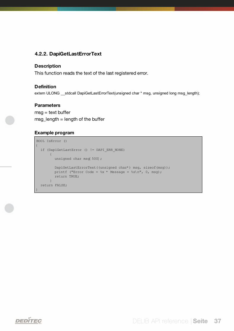
4.2.2. DapiGetLastErrorText
Description
This function reads the text of the last registered error.
Definition
extern ULONG __stdcall DapiGetLastErrorText(unsigned char * msg, unsigned long msg_length);
Parameters
msg = text buffer
msg_length = length of the buffer
Example program
BOOL IsError (){ if (DapiGetLastError () != DAPI_ERR_NONE)
{ unsigned char msg[500];
DapiGetLastErrorText((unsigned char*) msg, sizeof(msg)); printf ("Error Code = %x * Message = %s\n", 0, msg); return TRUE;}
return FALSE;}

DELIB API reference | Seite 38
4.3. Reading Digital inputs
4.3.1. DapiDIGet1
Description
This command reads a single digit input.
Definition
ULONG DapiDIGet1(ULONG handle, ULONG ch);
Parameters
handle=This is the handle of an opened module.
ch=Specifies the number of input that is to be read (0 ..).
Return value
State of the input (0 / 1).

DELIB API reference | Seite 39
4.3.2. DapiDIGet8
Description
This command reads 8 digital inputs simultaneously.
Definition
ULONG DapiDIGet8(ULONG handle, ULONG ch);
Parameters
handle=This is the handle of an opened module.
ch=Specifies the number of the input, from which it begins to read from (0, 8,16, 24, 32, ..)
Return value
State of the read inputs.

DELIB API reference | Seite 40
4.3.3. DapiDIGet16
Description
This command reads 16 digital inputs simultaneously.
DefinitionULONG DapiDIGet16(ULONG handle, ULONG ch);
Parameters
handle=This is the handle of an opened module.
ch=Specifies the number of the input, from which it begins to read from (0, 16,32, ..)
Return value
State of the read inputs.

DELIB API reference | Seite 41
4.3.4. DapiDIGet32
Description
This command reads 32 digital inputs simultaneously.
Definition
ULONG DapiDIGet32(ULONG handle, ULONG ch);
Parameters
handle=This is the handle of an opened module.
ch=Specifies the number of the input, from which it begins to read from (0, 32,64, ..)
Return value
State of the read inputs.
Example program
unsigned long data;// ----------------------------------------------------// Einen Wert von den Eingängen lesen (Eingang 1-31)data = (unsigned long) DapiDIGet32(handle, 0);// Chan Start = 0printf("Eingang 0-31 : 0x%x\n", data);printf("Taste für weiter\n");getch();// ----------------------------------------------------// Einen Wert von den Eingängen lesen (Eingang 32-64)data = (unsigned long) DapiDIGet32(handle, 32);// Chan Start = 32printf("Eingang 32-64 : 0x%x\n", data);printf("Taste für weiter\n");getch();

DELIB API reference | Seite 42
4.3.5. DapiDIGet64
Description
This command reads 64 digital inputs simultaneously.
Definition
ULONGLONG DapiDIGet64(ULONG handle, ULONG ch);
Parameters
handle=This is the handle of an opened module.
ch=Specifies the number of the input,from which it begins to read from (0, 64, ..)
Return value
State of the read inputs.

DELIB API reference | Seite 43
4.3.6. DapiDIGetFF32
Description
This command reads the flip-flops from the inputs and resets them. (Input statechange).
Definition
ULONGLONG DapiDIGet64(ULONG handle, ULONG ch);
Parameters
handle=This is the handle of an opened module .
ch=Specifies the number of the input, from which it begins to read from (0, 32,..)
Return value
State of 32 input change states

DELIB API reference | Seite 44
4.3.7. DapiDIGetCounter
Description
This command reads the counter of a digital input
Definition
ULONG DapiDIGetCounter(handle, ch, par1);
Parameters
handle=This is the handle of an opened module.
ch=Specifies the digital input, from which the counter will be read
par1=0 (Normal counter function)
par1=DAPI_CNT_MODE_READ_WITH_RESET (Reading and resetting thecounter)
Return value
Value of the counter.
Example program
value = DapiDIGetCounter(handle, 0 ,0);// Reading counter of DI Chan 0
value = DapiDIGetCounter(handle, 1 ,0);// Reading counter of DI Chan 1
value = DapiDIGetCounter(handle, 8 ,0);// Reading counter of DI Chan 8
value = DapiDIGetCounter(handle, 0 ,DAPI_CNT_MODE_READ_WITH_RESET);// Reading AND resetting counter of DI Chan 0

DELIB API reference | Seite 45
4.4. Setting Digital outputs
4.4.1. DapiDOSet1
Description
This is the command to set a single output.
Definitionvoid DapiDOSet1(ULONG handle, ULONG ch, ULONG data);
Parameters
handle=This is the handle of an opened module
ch=Specifies the number of the output to be set to (0 ..)
data=Specifies the data value that is to be written (0 / 1)
Return value
None

DELIB API reference | Seite 46
4.4.2. DapiDOSet8
Description
This command sets 8 digital outputs simultaneously.
Definition
void DapiDOSet8(ULONG handle, ULONG ch, ULONG data);
Parameters
handle=This is the handle of an opened module
ch=Specifies the number of the output, from which it begins to write to (0, 8, 16,24, 32, ..)
data=Specifies the data values, to write to the outputs
Return value
None

DELIB API reference | Seite 47
4.4.3. DapiDOSet16
Description
This command sets 16 digital outputs simultaneously.
Definition
void DapiDOSet16(ULONG handle, ULONG ch, ULONG data);
Parameters
handle=This is the handle of an opened module
ch=Specifies the number of the output, from which it begins to write to (0, 16,32, ..)
data=Specifies the data values, to write to the outputs
Return value
None

DELIB API reference | Seite 48
4.4.4. DapiDOSet32
Description
This command sets 32 digital outputs simultaneously.
Definition
void DapiDOSet32(ULONG handle, ULONG ch, ULONG data);
Parameters
handle=This is the handle of an opened module
ch=Specifies the number of the output, from which it begins to write to (0, 32,64, ..)
data=Specifies the data values, to write to the outputs
Return value
None
Example program
// Einen Wert auf die Ausgänge schreibendata = 0x0000ff00; // Ausgänge 9-16 werden auf 1 gesetztDapiDOSet32(handle, 0, data); // Chan Start = 0printf("Schreibe auf Ausgänge Daten=0x%x\n", data);printf("Taste für weiter\n");getch();// ----------------------------------------------------// Einen Wert auf die Ausgänge schreibendata = 0x80000000; // Ausgang 32 wird auf 1 gesetztDapiDOSet32(handle, 0, data); // Chan Start = 0printf("Schreibe auf Ausgänge Daten=0x%x\n", data);printf("Taste für weiter\n");getch();// ----------------------------------------------------// Einen Wert auf die Ausgänge schreibendata = 0x80000000; // Ausgang 64 wird auf 1 gesetztDapiDOSet32(handle, 32, data); // Chan Start = 32printf("Schreibe auf Ausgänge Daten=0x%x\n", data);printf("Taste für weiter\n");getch();

DELIB API reference | Seite 49
4.4.5. DapiDOSet64
Description
This command is to set 64 digital outputs.
Definition
void DapiDOSet64(ULONG handle, ULONG ch, ULONG data);
Parameters
handle=This is the handle of an opened module
ch=Specifies the number of the output, from which it begins to write to (0, 64, ..)
data=Specifies the data values, to write to the outputs
Return value
None

DELIB API reference | Seite 50
4.4.6. DapiDOReadback32
Description
This command reads back the 32 digital outputs.
Definition
ULONG DapiDOReadback32(ULONG handle, ULONG ch);
Parameters
handle=This is the handle of an opened module
ch=Specifies the number of the input, from which it begins to read from (0, 32,..)
Return value
Status of 32 outputs.

DELIB API reference | Seite 51
4.4.7. DapiDOReadback64
Description
This command reads back the 64 digital outputs.
Definition
ULONGLONG DapiDOReadback64(ULONG handle, ULONG ch);
Parameters
handle=This is the handle of an opened module
ch=Specifies the number of the input, from which it begins to read from (0, 64,..)
Return value
Status of 64 outputs.

DELIB API reference | Seite 52
4.5. Output timeout management
4.5.1. DapiSpecialCMDTimeout
Description
This command serves to set the timeout time
Definition
DapiSpecialCommand(handle, DAPI_SPECIAL_CMD_TIMEOUT, cmd, par1, par2);
Parameters
handle=This is the handle of an opened module
Set timeout time
cmd=DAPI_SPECIAL_CMD_TIMEOUT_SET_VALUE_SEC
par1=Seconds [s]
par2=Milliseconds [100ms] (value 6 stands for 600ms)
Activate timeout
cmd=DAPI_SPECIAL_CMD_TIMEOUT_ACTIVATE
Deactivate timeout
cmd=DAPI_SPECIAL_CMD_TIMEOUT_DEACTIVATE
Return value
None
Example program
DapiSpecialCommand(handle, DAPI_SPECIAL_CMD_TIMEOUT,DAPI_SPECIAL_TIMEOUT_SET_VALUE_SEC, 3, 7);//Die Zeit des Timeouts wird auf 3,7sek gesetzt.DapiSpecialCommand(handle, DAPI_SPECIAL_CMD_TIMEOUT,DAPI_SPECIAL_TIMEOUT_ACTIVATE, 0, 0);//Der Timeout wird aktiviert.DapiSpecialCommand(handle, DAPI_SPECIAL_CMD_TIMEOUT,DAPI_SPECIAL_TIMEOUT_DEACTIVATE, 0, 0);//Der Timeout wird deaktiviert.

DELIB API reference | Seite 53
4.5.2. DapiSpecialCMDTimeoutGetStatus
Description
This command reads the timeout status.
Definition
ULONG DapiSpecialCommand(handle, DAPI_SPECIAL_CMD_TIMEOUT,DAPI_SPECIAL_TIMEOUT_GET_STATUS, 0, 0);
Parameters
handle=This is the handle of an opened module
Return value
Return=0 (timeout is deactivated)
Return=1 (timeout is activated)
Return=2 (timeout has occurred)
Example program
status = DapiSpecialCommand(handle, DAPI_SPECIAL_CMD_TIMEOUT,DAPI_SPECIAL_TIMEOUT_GET_STATUS, 0, 0); //Abfrage des Timeout-Status.

DELIB API reference | Seite 54
4.6. Test functions
4.6.1. DapiPing
Description
This command checks the connection of an opened module.
Definition
ULONG DapiPing(ULONG handle, ULONG value);
Parameters
handle=This is the handle of an opened module
value=Given test value to the module
Return value
The given test-value “value“ is also the return value

DELIB API reference | Seite 55
4.7. Example program
// ****************************************************************************// ****************************************************************************// ****************************************************************************// ****************************************************************************// ****************************************************************************//// (c) DEDITEC GmbH, 2009//// web: http://www.deditec.de//// mail: [email protected]//////// dtapi_prog_beispiel_input_output.cpp////// ****************************************************************************// ****************************************************************************// ****************************************************************************// ****************************************************************************// ****************************************************************************////// Folgende Bibliotheken beim Linken mit einbinden: delib.lib// Dies bitte in den Projekteinstellungen (Projekt/Einstellungen/Linker(Objekt-Bibliothek-Module) .. letzter Eintrag konfigurieren#include <windows.h>#include <stdio.h>#include "conio.h"#include "delib.h"// ----------------------------------------------------------------------------// ----------------------------------------------------------------------------// ----------------------------------------------------------------------------// ----------------------------------------------------------------------------// ----------------------------------------------------------------------------
void main(void){unsigned long handle;unsigned long data;unsigned long anz;unsigned long i;unsigned long chan;// ----------------------------------------------------// USB-Modul öffnenhandle = DapiOpenModule(USB_Interface8,0);printf("USB_Interface8 handle = %x\n", handle);if (handle==0){// USB Modul wurde nicht gefundenprintf("Modul konnte nicht geöffnet werden\n");printf("TASTE für weiter\n");getch();

DELIB API reference | Seite 56
return;}// Zum Testen - ein Ping senden// ----------------------------------------------------printf("PING\n");anz=10;for(i=0;i!=anz;++i){data=DapiPing(handle, i);if(i==data){// OKprintf(".");}else{// No answerprintf("E");}}printf("\n");
// ----------------------------------------------------// Einen Wert auf die Ausgänge schreibendata = 255;DapiWriteByte(handle, 0, data);printf("Schreibe auf Adresse=0 daten=0x%x\n", data);// ----------------------------------------------------// Einen Wert auf die Ausgänge schreibendata = 255;DapiWriteByte(handle, 1, data);printf("Schreibe auf Adresse=0 daten=0x%x\n", data);// ----------------------------------------------------// Einen Wert auf die Ausgänge schreibendata = 255;DapiWriteByte(handle, 2, data);printf("Schreibe auf Adresse=2 daten=0x%x\n", data);// ----------------------------------------------------// Einen Wert von den Eingängen lesendata = (unsigned long) DapiReadByte(handle, 0);printf("Gelesene Daten = 0x%x\n", data);// ----------------------------------------------------// Einen A/D Wert lesenchan=11; // read chan. 11data = DapiReadWord(handle, 0xff010000 + chan*2);printf("Adress=%x, ret=%x volt=%f\n", chan, data, ((float) data) / 1024*5);//Bei 5 Volt Ref// ----------------------------------------------------// Modul wieder schliessenDapiCloseModule(handle);printf("TASTE für weiter\n");getch();return ;}

V
Appendix | Seite 57
Appendix

Appendix | Seite 58
5. Appendix
5.1. Revisions
Rev 1.00 First issue
Rev 2.00 Design change

Appendix | Seite 59
5.2. Copyrights and trademarks
Linux is registered trade-mark of Linus Torvalds.
Windows CE is registered trade-mark of Microsoft Corporation.
USB is registered trade-mark of USB Implementers Forum Inc.
LabVIEW is registered trade-mark of National Instruments.
Intel is registered trade-mark of Intel Corporation
AMD is registered trade-mark of Advanced Micro Devices, Inc.

Hardware-Description
November
RO-Series
2010

INDEX
Index | 2Seite
1. Introduction 10
1.1. General remarks 10
1.2. Customer satisfaction 10
1.3. Customer response 10
2. Hardware description 12
2.1. Ethernet Interface 12
122.1.1. Hardware description 122.1.1.1. Overview screen
142.1.1.2. Technical data
152.1.1.3. Plug-in connector of the module
152.1.1.3.1. Power supply
152.1.1.3.2. Ethernet interface
162.1.1.4. Buttons of the module
172.1.1.5. Controll LEDs
172.1.1.5.1. Definition of LEDs
182.1.2. Restore basic configuration 182.1.2.1. Restore IP address
182.1.2.2. Restore firmware
192.1.3. Firmware Update 192.1.3.1. DEDITEC Flasher
202.1.3.2. Web interface
222.1.4. Configuring the module 222.1.4.1. Configuration via DELIB Configuration utility
262.1.4.2. Configuration via internal web server
272.1.4.3. Factory settings
2.2. CAN Interface 28
282.2.1. Hardware description 282.2.1.1. Overview screen
292.2.1.2. Technical data
302.2.1.3. Plug-in connector of the module
302.2.1.3.1. Power supply
302.2.1.3.2. CAN interface
312.2.1.4. Control LEDs
312.2.1.4.1. Definition of LEDs

INDEX
Index | 3Seite
322.2.2. Configuring the module 322.2.2.1. DIP-switches
332.2.2.2. The “special mode”
342.2.2.3. Software mode
362.2.2.4. DIP-switch mode
362.2.2.4.1. Setting up the transfer rate
372.2.2.4.2. Setting up the CAN module address
2.3. RS-232/RS-485 Interface 39
392.3.1. Hardware description 392.3.1.1. Overview screen
402.3.1.2. Technical data
412.3.1.3. Selecting between RS-232 or RS-485 interface
432.3.1.4. Plug-in connector of the module
432.3.1.4.1. Power supply
432.3.1.4.2. RS-232/RS-485 Interface 442.3.1.4.2.1RS-232 Pinout
442.3.1.4.2.2RS-485 Pinout
452.3.1.5. Control LEDs
452.3.1.5.1. Definition of LEDs
462.3.2. Configuring the module 462.3.2.1. DIP-switches
472.3.2.2. The "special-mode"
472.3.2.3. Activating echo
482.3.2.4. Setting up Baud rate
492.3.2.5. Setting up module address (RS-485 only)
2.4. USB Interface 50
502.4.1. Hardware description 502.4.1.1. Overview screen
512.4.1.2. Technical data
522.4.1.3. Plug-in connector of the module
522.4.1.3.1. Power supply
522.4.1.3.2. USB interface
532.4.1.4. Control LEDs
532.4.1.4.1. Definition of the LEDs
2.5. Digital in-/output modules 54
542.5.1. Hardware description 552.5.1.1. Opto-coupler inputs

INDEX
Index | 4Seite
552.5.1.1.1. Overview screen
562.5.1.1.2. Technical data
572.5.1.1.3. 16-bit counter
572.5.1.1.4. Registering short input pulses
572.5.1.1.5. Galvanically decouppled through optocouplers
582.5.1.1.6. Plug-in connector on the module 582.5.1.1.6.1Connection wiring
592.5.1.1.6.2Visual control of the inputs
592.5.1.1.6.3Pinout
592.5.1.1.7. Variable input voltage range 602.5.1.1.7.1Changing the input voltage
612.5.1.2. Relay outputs
612.5.1.2.1. Overview screen
622.5.1.2.2. Technical data
632.5.1.2.3. Timeout-protection
632.5.1.2.4. Plug-in connector on the module 632.5.1.2.4.1Relay-outputs (galvanically decoupled, max. 1A)
642.5.1.2.4.2Connection wiring
642.5.1.2.4.3Visual control of the outputs
642.5.1.2.4.4Pinout
652.5.1.3. MOSFET outputs
652.5.1.3.1. Overview screen
662.5.1.3.2. Technical data
672.5.1.3.3. Timeout-protection
672.5.1.3.4. Plug-in connector on the module 672.5.1.3.4.1Optocoupler-outputs (galvanically isolated, max. 2A DC)
682.5.1.3.4.2Connection wiring
682.5.1.3.4.3Pinout
2.6. Analog in-/output modules 69
692.6.1. Hardware description 692.6.1.1. RO-AD16-DA4
702.6.1.1.1. Overview screen
712.6.1.1.2. Technical data
722.6.1.1.3. Timeout-protection
732.6.1.1.4. Pinout 732.6.1.1.4.1A/D connection wiring (18pol)
732.6.1.1.4.2D/A connection wiring (10pol)
742.6.1.2. RO-AD16
742.6.1.2.1. Overview screen

INDEX
Index | 5Seite
752.6.1.2.2. Technical data
762.6.1.2.3. Pinout 762.6.1.2.3.1A/D connection wiring (18pol)
772.6.1.3. RO-AD16_ISO
772.6.1.3.1. Overview screen
782.6.1.3.2. Technical data
792.6.1.3.3. Pinout 792.6.1.3.3.1A/D connection wiring (18pol)
802.6.1.4. RO-DA4
802.6.1.4.1. Overview screen
812.6.1.4.2. Technical data
822.6.1.4.3. Timeout-protection
822.6.1.4.4. Pinout 822.6.1.4.4.1D/A connection wiring (10pol)
832.6.1.5. RO-DA2_ISO
832.6.1.5.1. Overview screen
842.6.1.5.2. Technical data
852.6.1.5.3. Timeout-protection
862.6.1.5.4. Pinout 862.6.1.5.4.1D/A connection wiring (10pol)
2.7. Stepper module 87
872.7.1. Hardware description 872.7.1.1. Overview screen
882.7.1.2. Technical data
882.7.1.3. Stepping motor control
892.7.1.4. Stepper connection wiring (10pol) - pinout
3. Software 91
3.1. Using our products 91
913.1.1. Access via graphical applications 913.1.2. Access via the DELIB driver library 913.1.3. Access via protocol 923.1.4. Access via provided test programs
3.2. DELIB driver library 93
933.2.1. Overview 953.2.2. Supported operating systems 953.2.3. Supported programming languages

INDEX
Index | 6Seite
963.2.4. Installation DELIB driver library 983.2.5. DELIB Configuration Utility
3.3. Test programs 99
993.3.1. Digital Input-Output Demo 1003.3.2. Analog Input-Output Demo 1013.3.3. Stepper Demo
4. DELIB API reference 103
4.1. Management functions 103
1034.1.1. DapiOpenModule 1044.1.2. DapiCloseModule
4.2. Error handling 105
1054.2.1. DapiGetLastError 1064.2.2. DapiGetLastErrorText
4.3. Reading Digital inputs 107
1074.3.1. DapiDIGet1 1084.3.2. DapiDIGet8 1094.3.3. DapiDIGet16 1104.3.4. DapiDIGet32 1114.3.5. DapiDIGet64 1124.3.6. DapiDIGetFF32 1134.3.7. DapiDIGetCounter
4.4. Setting Digital outputs 114
1144.4.1. DapiDOSet1 1154.4.2. DapiDOSet8 1164.4.3. DapiDOSet16 1174.4.4. DapiDOSet32 1184.4.5. DapiDOSet64 1194.4.6. DapiDOReadback32 1204.4.7. DapiDOReadback64
4.5. A/D converter functions 121
1214.5.1. DapiADSetMode 1234.5.2. DapiADGetMode 1244.5.3. DapiADGet

INDEX
Index | 7Seite
1254.5.4. DapiADGetVolt 1264.5.5. DapiADGetmA
4.6. D/A outputs management 127
1274.6.1. DapiDASetMode 1294.6.2. DapiDAGetMode 1304.6.3. DapiDASet 1314.6.4. DapiDASetVolt 1324.6.5. DapiDASetmA 1334.6.6. DapiSpecialCmd_DA
4.7. Stepper motor functions 135
1354.7.1. DapiStepperCommands 1354.7.1.1. DAPI_STEPPER_CMD_GO_POSITION
136
4.7.1.2.
DAPI_STEPPER_CMD_GO_POSITION_RELATIVE
1374.7.1.3. DAPI_STEPPER_CMD_SET_POSITION
1384.7.1.4. DAPI_STEPPER_CMD_SET_FREQUENCY
1394.7.1.5. DAPI_STEPPER_CMD_GET_FREQUENCY
140
4.7.1.6.
DAPI_STEPPER_CMD_SET_FREQUENCY_DIRECTLY
1414.7.1.7. DAPI_STEPPER_CMD_STOP
1424.7.1.8. DAPI_STEPPER_CMD_FULLSTOP
1434.7.1.9. DAPI_STEPPER_CMD_DISABLE
144
4.7.1.10.
DAPI_STEPPER_CMD_SET_MOTORCHARACTERISTIC
149
4.7.1.11.
DAPI_STEPPER_CMD_GET_MOTORCHARACTERISTIC
157
4.7.1.12.
DAPI_STEPPER_CMD_MOTORCHARACTERISTIC_EEP
ROM_SAVE
158
4.7.1.13.
DAPI_STEPPER_CMD_MOTORCHARACTERISTIC_EEP
ROM_LOAD
159
4.7.1.14.
DAPI_STEPPER_CMD_MOTORCHARACTERISTIC_LOA
D_DEFAULT
1604.7.1.15. DAPI_STEPPER_CMD_GO_REFSWITCH
1614.7.1.16. DAPI_STEPPER_CMD_GET_CPU_TEMP
162
4.7.1.17.
DAPI_STEPPER_CMD_GET_MOTOR_SUPPLY_VOLTAG
E

INDEX
Index | 8Seite
1634.7.2. DapiStepperGetStatus 1634.7.2.1. DAPI_STEPPER_STATUS_GET_ACTIVITY
1644.7.2.2. DAPI_STEPPER_STATUS_GET_POSITION
1654.7.2.3. DAPI_STEPPER_STATUS_GET_SWITCH
1664.7.3. DapiStepperCommandEx
4.8. Output timeout management 167
1674.8.1. DapiSpecialCMDTimeout 1684.8.2. DapiSpecialCMDTimeoutGetStatus
4.9. Test functions 169
1694.9.1. DapiPing
4.10. Example program 170
5. Appendix 173
5.1. Revisions 173
5.2. Copyrights and trademarks 174

I
Introduction |Seite 9
Introduction

Introduction |Seite 10
1. Introduction
1.1. General remarks
First of all, we would like to congratulate you to the purchase of a high qualityDEDITEC product.
Our products are being developed by our engineers according to qualityrequirements of high standard. Already during design and development we takecare that our products have -besides quality- a long availability and an optimalflexibility.
Modular design
The modular design of our products reduces the time and the cost ofdevelopment. Therefor we can offer you high quality products at a competitiveprice.
Availability
Because of the modular design of our products, we have to redesign only amodule instead of the whole product, in case a specific component is no longeravailable.
1.2. Customer satisfaction
Our philosophy: a content customer will come again. Therefor customersatisfaction is in first place for us.
If by any chance, you are not content with the performance of our product,please contact us by phone or mail immediately.
We take care of the problem.
1.3. Customer response
Our best products are co-developments together with our customers. Thereforwe are thankful for comments and suggestions.

II
Hardware description |Seite 11
Hardware description

Hardware description |Seite 12
2. Hardware description
2.1. Ethernet Interface
2.1.1. Hardware description
2.1.1.1. Overview screen
The figure shows the control module with ethernet interface (left side) combinedwith an input/output module (right side).

Hardware description |Seite 13
The figure shows the control module with ethernet interface (left side) combinedwith a flexible connector input/output module (right side).

Hardware description |Seite 14
2.1.1.2. Technical data
Single power supply +7V..+24V DC
10/100 Mbit/sec Ethernet interface
Input/output access over TCP/IP
WEB interface
Configuration over web interface
9 Control LEDs
RJ45 Socket
Timeout feature providing ability to disconnect outputs for safety reasons
Expandable in 16 gradations
Can be combined without any problem to other modules of the RO series
Windows driver library DELIB

Hardware description |Seite 15
2.1.1.3. Plug-in connector of the module
2.1.1.3.1. Power supply
The input-power-supply-range lies between +7V and +24V DC.The powersupply can be realized with a standard AC/DC adaptor with 1A output current. Asuitable plug-in connector is delivered.
2.1.1.3.2. Ethernet interface
The network connection is provided by a RJ45 socket.
LED Description
1 Activity
2 10/100 Mbit

Hardware description |Seite 16
2.1.1.4. Buttons of the module
Left Button:
Reset IP address to default
(see chapter 5.1)
Right Button:
Reset firmware to factory settings.
(see chapter 5.2)

Hardware description |Seite 17
2.1.1.5. Controll LEDs
The Ethernet module has a series of control LEDs. They are used for easy visualindication of various state functions.
While switching the module on, in normal operating mode, the module shouldsignalize the following sequence:
approx. 20 sec after switching the module on, LED 1 and 2 are flashing briefly.-> Operating system has been loaded successfully.
Then LED 3 is on permanently and LED 1 is flashing. -> Module is ready.
2.1.1.5.1. Definition of LEDs
LED Label Description
above 3,3V Internal 3,3V power supply
above 5V Internal 5V power supply
1 CPU Activity 2x flashing + long break. Operating system reports:Status OK
2 InterfaceActivity
Active communication over Ethernet
3 Status LED is on -> Module is ready
4 ERROR Error during ethernet-transfer (for details see document”Serial protocol”)
5 Inputs:Change
"State change" between 2 read-out cycles detected
6 Outputs: Auto-Off
Due to timeout, all outputs are switched-off for safetyreasons
7 I/O Access CPU-access to the connected I/O modules.

Hardware description |Seite 18
2.1.2. Restore basic configuration
2.1.2.1. Restore IP address
The default value of the IP address is: 192.168.1.1
Left Button: Restore IP address to default (192.168.1.1):
To restore the IP address proceed as follow:
Push the button at least 5 sec.
After that, the left LEDs "CPU Activity" and "Interface Activity" should beflashing four times (confirmation of receipt)
After this, the module has following settings:
IP address 192.168.1.1
Subnet mask 255.255.255.0
Standard gateway 192.168.1.254
2.1.2.2. Restore firmware
To restore the firmware to default value proceed as follow:
Right Button: Restore firmware to factory settings
To restore the firmware to factory settings proceed as follow:
Press the button at least 10sec.
After this, the three LED‘s “CPU Activity”, “Interface Activity” and “Status”should be flashing four times (confirmation of receipt).
After this, the module restarts.
The firmware and configuration of the factory settings are now active again!

Hardware description |Seite 19
2.1.3. Firmware Update
2.1.3.1. DEDITEC Flasher
Approach:
Download the latest firmware inclusive software update. http://www.deditec.de/en/module/software/delib/download.html
Extract all data to one folder
Start the application deditec-flasher.exe
1. Select the interface. For ethernet press the key "E"
2. Select the module which you want to update. Press the key "M" for CPUinterface
3. After successfully flashing , in the prompt appears: Flash OK!

Hardware description |Seite 20
2.1.3.2. Web interface
Approach:
1. Type the IP address of your module in the browser

Hardware description |Seite 21
1. Click on FW-Update
2. Select the file “ro_cpu_eth_fw.dfw”
3. Click on Firmware update

Hardware description |Seite 22
2.1.4. Configuring the module
2.1.4.1. Configuration via DELIB Configuration utility
This method allows a simple configuration of the product. Following basicvalues can be changed.
Module name
IP address
Net mask
Default gateway
DNS server
Additionally with this tool all DEDITEC ethernet devices in the LAN network aredisplayed.
The following pages describe how it works...

Hardware description |Seite 23
Start DELIB Configuration utility as follows:
Start -> Programs -> DEDITEC -> DELIB -> DELIB Configuration Utility
1. Module Selection: select RO-ETH
2. Find and configure RO-ETH Module

Hardware description |Seite 24
1. Scan RO-ETH modules: So you can find all DEDITEC ETH modules on localethernet stream. Therefore we use an ethernet protocol which will not berouted. Because of that you can configure only modules which are connectedto the bus. The advantage of this method is, that you can find modules whichare not in the same sub net, of which you are configuring.
2. Click on the module, which you want to configure.

Hardware description |Seite 25
Here you can change the module name according to your wishes
1. You can change module name, IP address, net mask, default gateway andDNS server.
2. Write new Values to Module.
Notice:
At the configuration of the RO-ETH module should be paid attention to the IPaddress. It has to be in the same IP segment in which the control PC is. Ofcourse you must not select an already used IP address.
If the standard IP address of the module is not from the address range of thenetwork, the module will not be reachable by TCP/IP at the moment. Problemsof accessibility will also occur, if the IP address is already used. However the IPaddress and the net mask of the ethernet module are configurable by this utility.Alternatively you can connect the module to the PC and set the IP address andthe net mask directly. After the accessibility is given, the further configuration isensued by a browser via the integrated web server of the ethernet module.
To these belongs ask your system administrator.

Hardware description |Seite 26
2.1.4.2. Configuration via internal web server
The RO-ETH module has an own web server by which it can be configured, too.

Hardware description |Seite 27
2.1.4.3. Factory settings
The factory settings of the ethernet module include following settings:
IP address: 192.168.1.1
The factory settings can be restored by pushing the left button -> see chapter5.2
IP address 192.168.1.1
Subnet mask 255.255.255.0
Standard gateway 192.168.1.254

Hardware description |Seite 28
2.2. CAN Interface
2.2.1. Hardware description
2.2.1.1. Overview screen
The figure shows the control module with CAN-interface (left side) combinedwith an input/output module (right side).
The figure shows the control module with CAN-interface (left side) combinedwith a flexible connector input/output module (right side).

Hardware description |Seite 29
2.2.1.2. Technical data
Single power supply +7V..+24V DC
7 control LEDs
CAN 2.0A (11 Bit addressing)
CAN 2.0B (29 Bit addressing)
Transmission range up to 10km (at 10Kbit/s)
Easy to configure over DIP switches
Galvanically isolated interface using optocouplers
9 pol. D-SUB socket
Timeout feature providing ability to disconnect outputs for safety reasons
Comfortable connector system with ejection mechanism
Expandable in 16 gradations
Can be combined without any problem to other modules of the RO series

Hardware description |Seite 30
2.2.1.3. Plug-in connector of the module
2.2.1.3.1. Power supply
The input-power-supply-range lies between +7V and +24V DC. Power supplycan be realized with a standard AC/DC adaptor with 1A output current. Asuitable plug-in connector is included.
2.2.1.3.2. CAN interface
The connection to the CAN bus is realized through a 9 pol D-SUB connector. Itis galvanically isolated through optocouplers. The CAN module is configuredover the PC’s RS-232 interface using the the included adaptor plug.
Pin
1 RS-232 config
3 RS-232 config
2 CAN low
7 CAN high
5 GND

Hardware description |Seite 31
2.2.1.4. Control LEDs
The CAN module has a series of control LEDs. They are used for easy visualindication of various state functions.
While switching-on the module in DIP-switch mode oder software mode, themodule should signalize the following sequence:
all five LEDs flashing briefly
right LED (I/O access) flashing briefly
In ”special mode”, the following signal sequence should be seen:
all five LEDs flashing briefly
right LED (I/O access) flashing briefly
all five LEDs flashing briefly
2.2.1.4.1. Definition of LEDs
LED Description
3,3V Internal 3,3V power supply
5V Internal 5V power supply
InterfaceActivity
Active communication- over the CAN bus
ERROR Error during CAN-transfer (for details see document ”CANprotocol”)
Inputs:Change
State change between 2 read-out cylces detected
Outputs:Auto-Off
Due to timeout, all outputs are switched-off for safetyreasons
I/O Access CPU-access on the inputs and outputs of the connectedmodules

Hardware description |Seite 32
2.2.2. Configuring the module
In order to integrate a module into an existing bus system, it is necessary to firstassign a free module address and the appropriate bit rate. The ”special mode”may be alternatively used to quickly operate the system.
2.2.2.1. DIP-switches
Some of the settings are easily configurable using DIP-switches. Configurableare the ”special mode”, the activation of the extended IDs, the data transferrange or the module’s address.
DIP-switch A8 DIP-switch A7 Description
ON ON ”special mode” -> Blinking squencyduring start-up (5 LEDs, 1 right LED, 5LEDs), 100KHz, CAN-ID=0x100,Response-Module-Addr=1, keine 29 BitAdressen
ON OFF Only for SERVICE-purpose: applicationwon’t start. Forced into bootloader
OFF ON Software mode: configuration by software
OFF OFF DIP-switch mode: configuration by DIP-Switches, Response-Module-Addr=1,CAN 2.0A
DIP-switch Description
A6 to A4 *) Setting up transfer rate
A3 to A1 *) Setting up CAN address
B8 to B1 *) Setting up CAN address
*) if A8 and A7 = OFF

Hardware description |Seite 33
2.2.2.2. The “special mode”
The ”special mode” is to quickly and easily set the device to the default values.This is helpfull for a quick and easy setup and facilitates an error analysis or aninitial operation.
This mode is active, if switching the DIP-switches A7 and A8 to ”ON”. Theremaining DIP-switches are disabled. The module will work with the followingsettings:
11 bit-addressing
100 kbit/s bitrate
CAN-address = 0x100
Response-Modul-Addr = 1 (responses are sent to this address)

Hardware description |Seite 34
2.2.2.3. Software mode
This module can configured in “software mode” only with the small CAN/SERprogram adpater, which is included in delivery. Configuration will be done by theserial interface of your pc.
For using the software mode, the dip switches A7 and A8 must be set “on”. Dipswitch changes will be taken over, only by restart of the module.
Connect the module with a DSUB-9 cable to the RS-232 interface of your pcwith the CAN/SER adapter and connect it with the CAN-module.
After installing the DELIB driver library, you can find under Start ->Programs ->DEDITEC ->DELIB, the DELIB Configuration Utility.

Hardware description |Seite 35
Approach:
1. Choose the RO-CAN module
2. Choose COM port, that is connected to the module
3. Test commuikation with RO-CAN module
4. This button shows the config of the module
5. Here you can save your configuration to the module
6. This button loads the config of the module

Hardware description |Seite 36
2.2.2.4. DIP-switch mode
In this mode, the module is entirely set up by DIP-switch. This mode is active, ifDIP-switch A7=OFF and A8=OFF. The address range is 11 bit large (CAN 2.0A).The module-address is set using the DIP-switches (DIP A3..A1 und B8..B1). TheResponse-Modul-Addr = 1 (responses are sent to this address).
2.2.2.4.1. Setting up the transfer rate
The bit rate is dependent on the CAN bus data transfer range. 3 DIP-switchesare used to set the bit rate. Other bit rates can be implemented on customerrequest.
Bitrate 1Mbit 500K 250K 125K 100K 50K 20K 10K
DIP-switch A6 On On On On Off Off Off Off
DIP-switch A5 On On Off Off On On Off Off
DIP-switch A4 On Off On Off On Off On Off

Hardware description |Seite 37
2.2.2.4.2. Setting up the CAN module address
Any connected device to the CAN network needs a fix address in order to bedirectly accessed. With the 11 DIP-switches, up to 2047 different addresses areselectable. Further 18 addressing bits may be supplemented by software. Tounlock this option, DIP-switch 7A must be set to ON.
Baud rate Bit Value ON Value OFF
DIP-switch A3 Bit 10 1024 0
DIP-switch A2 Bit 9 512 0
DIP-switch A1 Bit 8 256 0
DIP-switch B8 Bit 7 128 0
DIP-switch B7 Bit 6 64 0
DIP-switch B6 Bit 5 32 0
DIP-switch B5 Bit 4 16 0
DIP-switch B4 Bit 3 8 0
DIP-switch B3 Bit 2 4 0
DIP-switch B2 Bit 1 2 0
DIP-switch B1 Bit 0 1 0

Hardware description |Seite 38
Examples:
Baud rate Address 0 Address 117 Address 588
DIP-switch A3 Off Off Off
DIP-switch A2 Off Off On
DIP-switch A1 Off Off Off
DIP-switch B8 Off Off Off
DIP-switch B7 Off On On
DIP-switch B6 Off On Off
DIP-switch B5 Off On Off
DIP-switch B4 Off Off On
DIP-switch B3 Off On On
DIP-switch B2 Off Off Off
DIP-switch B1 Off On Off

Hardware description |Seite 39
2.3. RS-232/RS-485 Interface
2.3.1. Hardware description
2.3.1.1. Overview screen
The figure shows the control module with RS-232/RS-485 interface (left side)combined with an input/output module (right side).
The figure shows the control module with a RS-232/RS-485 interface (left side)combined with a flexible conntector input/output module (right side).

Hardware description |Seite 40
2.3.1.2. Technical data
Single power supply +7V..+24V DC
7 control LEDs
RS-232/RS-485 interface
Easy to configure over DIP switches
Galvanically isolated interface using optocouplers
Connection through 9 pol. D-SUB connector
Timeout feature providing ability to disconnect outputs for safety reasons
Comfortable connector system with ejection mechanism
Expandable in 16 gradations
Can be combined without any problem to other modules of the RO series
Hardware description |Seite 41
2.3.1.3. Selecting between RS-232 or RS-485 interface
The factory setting mode of the interface is RS-232. The following describeshow to change the interface mode to RS-485.
Notice!
Bevore opening the device, please note the following:
Disconnect the power supply (unplug AC/DC adaptor)!
Do not touch electronic components. They could be destroyed by electrostaticdischarge! If necessary, touch grounded metal casings or radiators.
Remove a module‘s side element. Unscrew the three Phillips screws.
Pull the circuit board together with the front panel sideways out.
Lift the front panel from the module.
Next to the left side of the serial interface (D-SUB 9 pol. connector) is a 10pol.header with corresponding jumpers. The following table shows, which jumpersto plug-in.

Hardware description |Seite 42
Header Interface Set jumper
RS-232 Pin1 & Pin3
Pin2 & Pin4
RS-485
Resistanceterminator
Pin3 & Pin5
Pin4 & Pin6
Pin7 & Pin8
Pin9 & Pin10
Assembling the elements in done the reverse order.

Hardware description |Seite 43
2.3.1.4. Plug-in connector of the module
2.3.1.4.1. Power supply
The input-power-supply-range lies between +7V and +24V DC. Power supplycan be realized with a standard AC/DC adaptor with 1A output current. Asuitable plug-in connector is included.
2.3.1.4.2. RS-232/RS-485 Interface
The connection to the serial bus is realized through a 9 pol D-SUB conector. Itis galvanically isolated through optocouplers.

Hardware description |Seite 44
2.3.1.4.2.1. RS-232 Pinout
Pin
2 TX
3 RX
5 GND
2.3.1.4.2.2. RS-485 Pinout
Pin
2 RS-485 B
7 RS-485 A
5 GND

Hardware description |Seite 45
2.3.1.5. Control LEDs
The RS-232/RS-485 module has a series of control LEDs. They are used foreasy visual indication of various state functions.
While switching the module on in normal operating mode, the module shouldsignalize the following sequence:
- all five LEDs flashing briefly
- right LED (I/O access) flashing briefly
In ”special mode”, the following signal sequence should be seen:
- all five LEDs flashing briefly
- right LED (I/O access) flashing briefly
- all five LEDs flashing briefly
2.3.1.5.1. Definition of LEDs
LED Description
3,3V Internal 3,3V power supply
5V Internal 5V power supply
InterfaceActivity
Active communication over the RS-232/RS-485 bus
ERROR Error during serial-transfer (for details see document ”Serialprotocol”)
Inputs:Change
State change between 2 read-out cylces detected
Outputs:Auto-Off
Due to timeout, all outputs are switched-off for safetyreasons
I/O Access CPU-access on the inputs and outputs of the connectedmodules

Hardware description |Seite 46
2.3.2. Configuring the module
In order to integrate a module into an existing bus system, it is necessary to firstassign a free module address and the appropriate bit rate. The ”special mode”may be alternatively used to quickly operate the system.
2.3.2.1. DIP-switches
Some of the settings are easily configurable using DIP-switches. Configurableare ”special mode”, the Baud rate, the module’s address or interface-specificsettings.
DIP-switch A8 DIP-switch A7 Description
ON ON Special-mode(115K baud rate, module-address = 0,Echo = OFF)
ON OFF Only for SERVICE-purpose: applicationwon’t start. Forced into bootloader
OFF ON Use setup of DIP-switch A4..A1and B8..B1
OFF OFF Use setup of DIP-switch A4..A1and B8..B1
DIP-switch A6 Description
ON Echo = ON, serial received characters are sent back(Echo = OFF, if DIP A8 and A7 = ON)
OFF Echo = OFF
DIP-switch Description
A5 Reserved
A4 to A1 Setting up the baud rate
B8 to B1 Setting up the serial module number

Hardware description |Seite 47
2.3.2.2. The "special-mode"
The ”special mode” is to quickly and easily set the device to the default values.This is helpfull for a quick and easy setup and facilitates an error analysis or aninitial operation.
This mode is active, if switching the DIP-switches A7 and A8 to ”ON. Theremaining DIP-switches are disabled.
The module is now set to a baud rate of 115Kbauds, the module number and”echo” are inactive.
2.3.2.3. Activating echo
Received serial characters are returned back to display them on the monitor
(ON = yes, OFF = no).

Hardware description |Seite 48
2.3.2.4. Setting up Baud rate
The table lists the possible Baud rates. The trasfer rate is set using the 4 DIP-switches (A1 to A4).
Baud rate DIP-switchA4
DIP-switchA3
DIP-switch A2 DIP-switch A1
1,25 Mbit On On On On
625 Kbit On On On Off
250 Kbit On On Off On
125 Kbit On On Off Off
115200 Bit On Off On On
57600 Bit On Off On Off
50000 Bit On Off Off On
38400 Bit On Off Off Off
19200 Bit Off On On On
9600 Bit Off On On Off
4800 Bit Off On Off On
2400 Bit Off On Off Off
1200 Bit Off Off On On
600 Bit Off Off On Off
300 Bit Off Off Off On

Hardware description |Seite 49
2.3.2.5. Setting up module address (RS-485 only)
The operation in RS-485 mode allows to connect several modules to the bus. Itis therefore necessary to assign an individual address to each module. This isrealized by means of DIP-switches B1 to B8, resulting in a range of 0 to 255.The module-no. 0 is ignored, i.e. any no. will address the module.
Baud rate BIt Value ON Value OFF
DIP-switch B8 Bit 7 128 0
DIP-switch B7 Bit 6 64 0
DIP-switch B6 Bit 5 32 0
DIP-switch B5 Bit 4 16 0
DIP-switch B4 Bit 3 8 0
DIP-switch B3 Bit 2 4 0
DIP-switch B2 Bit 1 2 0
DIP-switch B1 Bit 0 1 0
Examples:
Baud rate Address 0 Address 25 Address 237
DIP-switch B8 Off Off On
DIP-switch B7 Off Off On
DIP-switch B6 Off Off On
DIP-switch B5 Off On Off
DIP-switch B4 Off On On
DIP-switch B3 Off Off On
DIP-switch B2 Off Off Off
DIP-switch B1 Off On On

Hardware description |Seite 50
2.4. USB Interface
2.4.1. Hardware description
2.4.1.1. Overview screen
The figure below shows the control module with USB-interface (left side)combined with an input/output module (right side). For a connection to the USBbus, an adequate adapter module in form of a USB-stick is included.
The figure below shows the control module with USB interface (left side)combined with a flexible conntector input/output module (right side). For aconnection to the USB bus, an adequate adapter module in form of a USB-stickis included with.

Hardware description |Seite 51
2.4.1.2. Technical data
Single power supply +7V..+24V DC
7 control LEDs
USB interface
Transmission range up to 100m!
USB 2.0 and USB 1.1
Data transfer speed: 12 MBit/s or 1,5 MBit/s
Galvanically isolated interface using optocouplers
9 pol. D-SUB connector
Timeout feature providing ability to disconnect outputs for safety reasons
Comfortable connector system with ejection mechanism
Expandable in 16 gradations
Can be combined without any problem to other modules of the RO series

Hardware description |Seite 52
2.4.1.3. Plug-in connector of the module
2.4.1.3.1. Power supply
The input-power-supply-range lies between +7V and +24V DC. Power supplycan be realized with a standard AC/DC adaptor with 1A output current. Asuitable plug-in connector is included.
2.4.1.3.2. USB interface
module in form of a USB stick with a connection cable. The stick has twooptocouplers ensuring a galvanical isolation to the PC.
The other end of the adapater is a 9 pol. D-SUB connector which is connectedto the RO-module.

Hardware description |Seite 53
2.4.1.4. Control LEDs
The USB module has a series of control LEDs. They are used for easy visualindication of various state functions.
While switching-on the module, it should signalize the following sequence:
all five LEDs flashing briefly
right LED (I/O access) flashing briefly
all five LEDs flashing briefly
2.4.1.4.1. Definition of the LEDs
LED Description
3,3V Internal 3,3V power supply
5V Internal 5V power supply
InterfaceActivity
Active communication- over the USB bus
ERROR Error during USB-transfer (for details see document ”USBprotocol”)
Inputs:Change
State change between 2 read-out cylces detected
Outputs:Auto-Off
Due to timeout, all outputs are switched-off for safetyreasons
I/O Access CPU-access on the inputs and outputs of the connectedmodules

Hardware description |Seite 54
2.5. Digital in-/output modules
2.5.1. Hardware description
Using the in-/output modules is based on two 16 pol. connectors with each 8different current circuits. Each state of these (total 16) current circuits issignalized by a LED. The modules are numbered from left to right (see overviewscreen).

Hardware description |Seite 55
2.5.1.1. Opto-coupler inputs
2.5.1.1.1. Overview screen
The figure shows two modules next to each other with correspondingnumbering of the terminal blocks.
The lower figure shows a flexible conntector module with 32 outputs andcorresponding numbered ports. Each outer end of the module has a 26 pol. wiretrap connector. Thus, multiple modules can be connected in series using aribbon cable for each connection.

Hardware description |Seite 56
2.5.1.1.2. Technical data
Variable power supply min. 5V, max. 30V AC
16-bit counter for the first 16 input channels
Pulse-detection between 2 read out cycles, indicated by LED
LED status indication of the inputs
Galvanically isolated using optocouplers
Comfortable connector system with ejection mechanism
Expandable in 16 gradations
Can be combined without any problem to other modules of the RO series

Hardware description |Seite 57
2.5.1.1.3. 16-bit counter
The first 16 input channels have each a 16 bit counter. Thus, events as lightbarriers, turnstiles or push-buttons are counted. Easy logical circuits arerealizable, which may e.g. switch one or several outputs, if a counter reached acertain amount (set-point is reached). Please refer to the manual ”RO-series” toimplement such logical circuits into software.
2.5.1.1.4. Registering short input pulses
Short input pulses between to read-out cycles are registered through anadditional logic and can be separately read-out. A registered pulse on one ormore inputs is signalized by the LED ”Inputs: Change” on the control module.The LED is extinguishing, if the software-register of the input state change isread out by the user. For more indformation, see ”Register assignment”.
2.5.1.1.5. Galvanically decouppled through optocouplers
AC input optocouplers provide a galvanic isolation of the module towards theconnected equipment. They also provide a safe connection to the module forreverse currents and high voltage peaks.

Hardware description |Seite 58
2.5.1.1.6. Plug-in connector on the module
As terminal block, user-friendly terminal strips with locking protection andejection mechanism are used. They are reverse-polarity protected and allowquick replugging. The wire connection itself is realised with a screwlessconnector system. A tool is included with each module.
2.5.1.1.6.1. Connection wiring
Connecting the wires is to be effected at the ports with the same numbering, forexample: 1a & 1b, 2a & 2b. ...
The optocoupler inputs are suitable for AC voltage. Therefore it is not necessaryto take care of the connection polarity.
The figure shows two terminal blocks with numbered connection ports.

Hardware description |Seite 59
2.5.1.1.6.2. Visual control of the inputs
The state of each input is directly signalized by a separate LED. This simplifiesto detect and rectify wiring errors, because the signals on the cables are directlyobservable.
2.5.1.1.6.3. Pinout
Port Pin Port Pin
1 1a & 1b 9 9a & 9b
2 2a & 2b 10 10a & 10b
3 3a & 3b 11 11a & 11b
4 4a & 4b 12 12a & 12b
5 5a & 5b 13 13a & 13b
6 6a & 6b 14 14a & 14b
7 7a & 7b 15 15a & 15b
8 8a & 8b 16 16a & 16b
2.5.1.1.7. Variable input voltage range
The factory-default of the inputs is set to a voltage range of 15V to 30V. Thismay be changed to a range of 5V to 15V (even afterward).
Input voltage range 5V – 15V 15V – 30V
Resistance value 1K 2K2

Hardware description |Seite 60
2.5.1.1.7.1. Changing the input voltage
Each terminal block has 8 inputs sudivided in two groups and each group has itsown input voltage range (resulting groups: 1-4, 5-8, 9-12 und 13-16). Eachgroup‘s input voltage range is defined by a corresponding resistor network.
The following steps describes how to exchange one or more resistor networks.
Notice!
Bevore opening the device, please note the following:
Disconnect the power supply (unplug AC/DC adaptor)!
Do not touch electronic components. They could be destroyed by electrostaticdischarge! If necessary, touch grounded metal casings or radiators.
Remove a module‘s side element. Unscrew the three Phillips screws.
Pull the circuit board together with the front panel sideways out.
Lift the front panel from the module.
Every input module has two single rowed socket terminal strips in which theresistor networks are plugged in. Please carefully remove the desired resistornetwork and replace them it appropriate one.
Assembling the elements in done the reverse order.

Hardware description |Seite 61
2.5.1.2. Relay outputs
2.5.1.2.1. Overview screen
The figure shows two modules next to each other with correspondingnumbering of the terminal blocks.
The lower figure shows a flexible conntector module with 32 outputs andcorresponding numbered ports. Each outer end of the module has a 26 pol. wiretrap connector. Thus, multiple modules can be connected in series using aribbon cable for each connection.

Hardware description |Seite 62
2.5.1.2.2. Technical data
Timeout-protection
LED status indication of the outputs
Galvanically isolated using optocouplers
Comfortable connector system with ejection mechanism
Expandable in 16 gradations
Can be combined without any problem to other modules of the RO series
Max. switching voltage: 36V
Max. switching current: 1A
Max. switching power: 20W
Switching cycles according to the manufacturer: 10 Mio.

Hardware description |Seite 63
2.5.1.2.3. Timeout-protection
The timeout-protection gives the possibility to switch-off automatically theoutputs on its own to prevent damage. This takes place, if in a predefined timeframe no communication with the module was possible. Reasons could be cabledisruption, PC-crash and more. This way damage control, surcharge ofconnected equipment and risk of accidents can be avoided. Switching off theoutputs is indicated by a LED.
2.5.1.2.4. Plug-in connector on the module
As terminal block, user-friendly terminal strips with locking protection andejection mechanism are used. They are reverse-polarity protected and allowquick replugging. The wire connection itself is realised with a screwlessconnector system. A tool is included with each module.
2.5.1.2.4.1. Relay-outputs (galvanically decoupled, max. 1A)
The relays are able to switch voltages up to 36V. The max. current is 1A at amax. power of 20W.
Additionally, the relays provide a safe electrical isolation of the module to theconnected equipment.

Hardware description |Seite 64
2.5.1.2.4.2. Connection wiring
Connecting the wires is to be effected at the ports with the same numbering, forexample: 1a & 1b, 2a & 2b. ...
It is not necessary to take care to the correct polarity.
2.5.1.2.4.3. Visual control of the outputs
The state of each output is directly signalized by a separate LED. This simplifiesto detect and rectify wiring errors, because the signals on the cables are directlyobservable.
2.5.1.2.4.4. Pinout
Port Pin Port Pin
1 1a & 1b 9 9a & 9b
2 2a & 2b 10 10a & 10b
3 3a & 3b 11 11a & 11b
4 4a & 4b 12 12a & 12b
5 5a & 5b 13 13a & 13b
6 6a & 6b 14 14a & 14b
7 7a & 7b 15 15a & 15b
8 8a & 8b 16 16a & 16b

Hardware description |Seite 65
2.5.1.3. MOSFET outputs
2.5.1.3.1. Overview screen
The figure shows two modules next to each other with correspondingnumbering of the terminal blocks.
The lower figure shows a flexible conntector module with 32 outputs andcorresponding numbered ports. Each outer end of the module has a 26 pol. wiretrap connector. Thus, multiple modules can be connected in series using aribbon cable for each connection.

Hardware description |Seite 66
2.5.1.3.2. Technical data
Timeout-protection
LED status indication of the outputs
Galvanically isolated using optocouplers
Comfortable connector system with ejection mechanism
Expandable in 16 gradations
Can be combined without any problem to other modules of the RO series
Max. switching voltage: 30V DC
Max. switching current: 2A DC
Max. switching power: 40W

Hardware description |Seite 67
2.5.1.3.3. Timeout-protection
The timeout-protection gives the possibility to switch-off automatically theoutputs on its own to prevent damage. This takes place, if in a predefined timeframe no communication with the module was possible. Reasons could be cabledisruption, PC-crash and more. This way damage control, surcharge ofconnected equipment and risk of accidents can be avoided. Switching off theoutputs is indicated by a LED.
2.5.1.3.4. Plug-in connector on the module
As terminal block, user-friendly terminal strips with locking protection andejection mechanism are used. They are reverse-polarity protected and allowquick replugging. The wire connection itself is realised with a screwlessconnector system. A tool is included with each module.
2.5.1.3.4.1. Optocoupler-outputs (galvanically isolated, max. 2A DC)
Every output is realized using high current optocouplers. Using optocouplersprovides a secure galvanical decoupling of the module-driven equipment to themodule itself.
Pay attention to the optocoupler’s output polarity while wiring (see figure below)!

Hardware description |Seite 68
2.5.1.3.4.2. Connection wiring
Connecting the wires is to be effected at the ports with the same numbering, forexample: 1a & 1b, 2a & 2b, ... Pay attention to the optocoupler’s output polaritywhile wiring, else the outputs will get damaged. Connect the positive voltage toport ”a”, and the switched positive voltage to port ”b”.
2.5.1.3.4.3. Pinout
Port Pin Port Pin
1 1a & 1b 9 9a & 9b
2 2a & 2b 10 10a & 10b
3 3a & 3b 11 11a & 11b
4 4a & 4b 12 12a & 12b
5 5a & 5b 13 13a & 13b
6 6a & 6b 14 14a & 14b
7 7a & 7b 15 15a & 15b
8 8a & 8b 16 16a & 16b

Hardware description |Seite 69
2.6. Analog in-/output modules
2.6.1. Hardware description
2.6.1.1. RO-AD16-DA4
This module has 16 A/D channels and provides a good basis to convert voltagesto digital values. It has furthermore 4 D/A outputs allowing to convert digitalvalues to an analog voltage.

Hardware description |Seite 70
2.6.1.1.1. Overview screen
The lower figure shows a module with two terminal blocks and correspondingnumbered connection ports.
The following figure shows a flexible conntector module with two terminalblocks and corresponding numbered connection ports.

Hardware description |Seite 71
2.6.1.1.2. Technical data
Timeout-protection
Comfortable connector system with ejection mechanism
Can be combined without any problem to other modules of the RO series
A/D outputs
Mode U: (voltage)
Unipolar: 0-5V, 0-10V
Bipolar: +5V, +10V
Mode I: (current)
Range: 0-20mA (optional)
D/A outputs
Timeout-protection
Mode U: (voltage)
Unipolar: 0V-5V, 0V-10V
Bipolar: +5V, +10V

Hardware description |Seite 72
2.6.1.1.3. Timeout-protection
The timeout-protection gives the possibility to switch automatically off theoutputs on its own to prevent damage. This takes place, if in a predefined timeframe no communication with the module was possible. Reasons could be cabledisruption, PC-crash and more. This way damage control, surcharge ofconnected equipment and risk of accidents can be avoided. Switching off theoutputs is indicated by a LED.

Hardware description |Seite 73
2.6.1.1.4. Pinout
2.6.1.1.4.1. A/D connection wiring (18pol)
Pin Pin
1 AGND 2 AGND
3 AD1 4 AD0
5 AD3 6 AD2
7 AD5 8 AD4
9 AD7 10 AD6
11 AD9 12 AD8
13 AD11 14 AD10
15 AD13 16 AD12
17 AD15 18 AD14
2.6.1.1.4.2. D/A connection wiring (10pol)
Pin Pin
1 AGND 2 DA0
3 AGND 4 DA1
5 AGND 6 DA2
7 AGND 8 DA3
9 AGND 10 AGND

Hardware description |Seite 74
2.6.1.2. RO-AD16
This module has 16 A/D input channels and provides a good basis to convertvoltages to digital values.
2.6.1.2.1. Overview screen
The lower figure shows a module with a terminal block and correspondingnumbered connection ports.
The following figure shows a flexible conntector module with a terminal blockand corresponding numbered connection ports.

Hardware description |Seite 75
2.6.1.2.2. Technical data
Timeout-protection
Comfortable connector system with ejection mechanism
Can be combined without any problem to other modules of the RO series
A/D inputs
Mode U: (voltage)
Unipolar: 0-5V, 0-10V
Bipolar: +5V, +10V
Mode I: (current)
Range: 0-20mA (optional)

Hardware description |Seite 76
2.6.1.2.3. Pinout
2.6.1.2.3.1. A/D connection wiring (18pol)
Pin Pin
1 AGND 2 AGND
3 AD1 4 AD0
5 AD3 6 AD2
7 AD5 8 AD4
9 AD7 10 AD6
11 AD9 12 AD8
13 AD11 14 AD10
15 AD13 16 AD12
17 AD15 18 AD14

Hardware description |Seite 77
2.6.1.3. RO-AD16_ISO
This module has 16 A/D input channels (galvancally isolated) and provides agood basis to convert voltages to digital values.
2.6.1.3.1. Overview screen
The lower figure shows a module with a terminal block and correspondingnumbered connection ports.
The following figure shows a flexible conntector module with a terminal blockand corresponding numbered connection ports.

Hardware description |Seite 78
2.6.1.3.2. Technical data
Timeout-protection
Comfortable connector system with ejection mechanism
Can be combined without any problem to other modules of the RO series
A/D inputs
Galvanically isolated
Mode U: (voltage)
Unipolar: 0-5V, 0-10V
Bipolar: +5V, +10V
Mode I: (current)
Range: 0-20mA (optional)

Hardware description |Seite 79
2.6.1.3.3. Pinout
2.6.1.3.3.1. A/D connection wiring (18pol)
Pin Pin
1 AGND 2 AGND
3 AD1 4 AD0
5 AD3 6 AD2
7 AD5 8 AD4
9 AD7 10 AD6
11 AD9 12 AD8
13 AD11 14 AD10
15 AD13 16 AD12
17 AD15 18 AD14

Hardware description |Seite 80
2.6.1.4. RO-DA4
This module has 4 D/A outputs and provides a good basis to convert digitalvalues to a voltage.
2.6.1.4.1. Overview screen
The lower figure shows a module with a terminal block and correspondingnumbered connection ports.
The following figure shows a flexible conntector module with a terminal blockand corresponding numbered connection ports.

Hardware description |Seite 81
2.6.1.4.2. Technical data
Timeout-protection
Comfortable connector system with ejection mechanism
Can be combined without any problem to other modules of the RO series
D/A outputs
Unipolar: 0V-5V, 0V-10V
Bipolar: +5V, +10V

Hardware description |Seite 82
2.6.1.4.3. Timeout-protection
The timeout-protection gives the possibility to switch automatically off theoutputs on its own to prevent damage. This takes place, if in a predefined timeframe no communication with the module was possible. Reasons could be cabledisruption, PC-crash and more. This way damage control, surcharge ofconnected equipment and risk of accidents can be avoided. Switching off theoutputs is indicated by a LED.
2.6.1.4.4. Pinout
2.6.1.4.4.1. D/A connection wiring (10pol)
Pin Pin
1 AGND 2 DA0
3 AGND 4 DA1
5 AGND 6 DA2
7 AGND 8 DA3
9 AGND 10 AGND

Hardware description |Seite 83
2.6.1.5. RO-DA2_ISO
This module has 2 galvanically decoupled D/A outputs and provides a goodbasis to convert digital values to a voltage.
2.6.1.5.1. Overview screen
The lower figure shows a module with a terminal block and correspondingnumbered connection ports.
The following figure shows a flexible conntector module with a terminal blockand corresponding numbered connection ports.

Hardware description |Seite 84
2.6.1.5.2. Technical data
Timeout-protection
Comfortable connector system with ejection mechanism
Can be combined without any problem to other modules of the RO series
D/A outputs
Modus U: (Spannung)
Unipolar: 0V-5V, 0V-10V
Bipolar: +5V, +10V
Mode I: (current)
Modus I: (Strom)
0-20mA, 4-20mA, 0-24mA

Hardware description |Seite 85
2.6.1.5.3. Timeout-protection
The timeout-protection gives the possibility to switch automatically off theoutputs on its own to prevent damage. This takes place, if in a predefined timeframe no communication with the module was possible. Reasons could be cabledisruption, PC-crash and more. This way damage control, surcharge ofconnected equipment and risk of accidents can be avoided. Switching off theoutputs is indicated by a LED.

Hardware description |Seite 86
2.6.1.5.4. Pinout
2.6.1.5.4.1. D/A connection wiring (10pol)
Connection wiring top:
Pin Pin
1 VOUT_A 2 +Vsense_A
3 VOUT_A 4 +Vsense_A
5 AGND 6 -Vsense_A
7 AGND 8 -Vsense_A
9 AGND 10 IOUT_A
Connection wiring bottom:
Pin Pin
1 VOUT_B 2 +Vsense_B
3 VOUT_B 4 +Vsense_B
5 AGND 6 -Vsense_B
7 AGND 8 -Vsense_B
9 AGND 10 IOUT_B

Hardware description |Seite 87
2.7. Stepper module
2.7.1. Hardware description
2.7.1.1. Overview screen
The lower figure shows a module with a terminal block and correspondingnumbered connection ports.
The following figure shows a flexible stepper module with a terminal block andcorresponding numbered connection ports.

Hardware description |Seite 88
2.7.1.2. Technical data
Common:
Module for two stepper motors
Comfortable connector system with ejection mechanism
Can be combined without any problem to other modules of the RO series
Configurable parameters
Start-/ stop frequency
Maximum stepping frequency
Acceleration slope
Deceleration slope
Phase current
Hold current
Hold time
2.7.1.3. Stepping motor control
Every parameter can be conveniently set using the DELIB library.
Two reference switches are used to reach a reference position. Two additionalend switches provide a save stopping. If they are operated, the motors mayexclusively be driven back in the opposite direction.

Hardware description |Seite 89
2.7.1.4. Stepper connection wiring (10pol) - pinout
Pinout of a socket connector and also of a stepper motor:
Pin Pin
1 24 V (motor powersupply)
2 0 V (motor power supply)
3 Phase 1 (+) 4 Reference switch 2*)
5 Phase 1 (-) 6 Reference switch 1*)
7 Phase 2 (+) 8 End switch 2 *)
9 Phase 2 (-) 10 End switch 1 *)
*) The switches must be connected towards 24 V.

III
Software |Seite 90
Software

Software |Seite 91
3. Software
3.1. Using our products
3.1.1. Access via graphical applications
We provide driverinterfaces e.g. for LabVIEW and ProfiLab. The DELIB driverlibrary is the basis, which can be directly activated by ProfiLAB.
For LabVIEW, we provide a simple driver connection with examples!
3.1.2. Access via the DELIB driver library
In the appendix, you can find the complete function reference for the integrationof our API-functions in your software. In addition we provide examples for thefollowing programming languages:
C
C++
C#
Delphi
VisualBasic
VB.NET
MS-Office
3.1.3. Access via protocol
The protocol for the activation of our products is open source. So you are ableto use our products on systems without Windows or Linux.

Software |Seite 92
3.1.4. Access via provided test programs
We provide simple handling test programs for the most important functions ofour products. These will be installed automatically by the installation of theDELIB driver library.
So you can test directly e.g. relays or you can check the voltage of an A/Dconverter.

Software |Seite 93
3.2. DELIB driver library
3.2.1. Overview
The following figure explains the structure of the DELIB driver library
The DELIB driver library allows an uniform response of DEDITEC hardware withparticular consideration of the following viewpoints:
Independent of operating system
Independent of programming language
Independent of the product
Program under diverse operating systems
The DELIB driver library allows an uniform response of our products on diverseoperating systems.
We has made sure, that all of our products can be responded by a fewcommands.Whatever which operating system you use. - Therefore the DELIB cares!

Software |Seite 94
Program with diverse programming languages
We provide uniform commands to create own applications. This will be solvedby the DELIB driver library.
You choose the programming language!
It can be simply developed applications under C++, C, Visual Basic, Delphi orLabVIEW®.
Program independent of the interface
Write your application independent of the interface !
Program an apllication for an USB product of us. - Also, it will work with anethernet or RS-232 product of us !
SDK-Kit for Programmer
Integrate the DELIB in your application. On demand you receive an installationscript for free, which allows you, to integrate the DELIB installation in yourapllication.

Software |Seite 95
3.2.2. Supported operating systems
Our products support the following operating systems:
Windows 2000
Windows XP
Windows Vista
Windows 7
Linux
3.2.3. Supported programming languages
Our products are responsive via the following programming languages:
C
C++
C#
Delphi
VisualBasic
VB.NET
MS-Office

Software |Seite 96
3.2.4. Installation DELIB driver library
DELIB stands for DEDITEC Library and contains the necessary libraries for themodules in the programming languages C, Delphi and Visual Basic.
Insert the DEDITEC driver CD into the drive and start „delib_install.exe“. The
DELIB driver library is also available on http://www.deditec.en/delib
Click on „Install“.

Software |Seite 97
The drivers will be installed.
The DELIB driver library is now installed. Press „Close“ to finish the installation.
You can configure your module with the „DELIB Configuration Utility“ (see
next chapter). This is only necessary, if more than one module is present.

Software |Seite 98
3.2.5. DELIB Configuration Utility
Start the “DELIB Configuration Utility” as follows:
Start Programs DEDITEC DELIB DELIB Configuration Utility.
The „DELIB Configuration Utility“ is a program to configure and subdivide
identical USB-modules in the system. This is only necessary if more than onemodule is present.

Software |Seite 99
3.3. Test programs
3.3.1. Digital Input-Output Demo
Start “Digital Input-Output Demo” as follows:
Start Programme DEDITEC DELIB Digital Input-Output Demo.
The screenshot shows a test of the RO-USB-O64-R64. The configuration of themodule (64 inputs and 64 outputs) is shown on the upper left side.

Software |Seite 100
3.3.2. Analog Input-Output Demo
Start “Analog Input-Output Demo” as follows:
Start Programme DEDITEC DELIB Analog Input-Output Demo.
The screenshot shows a test of the RO-USB-AD16-DA2_ISO. The configurationof the module (16 A/D inputs and 2 D/A outputs) is shown on the upper left side.

Software |Seite 101
3.3.3. Stepper Demo
Start “Stepper Demo” as follows:
Start Programme DEDITEC DELIB Stepper Demo.
The screenshot shows a test of the RO-USB-STEPPER2. The configuration ofthe module (2 Stepper) is shown on the upper left side.

IV
DELIB API reference |Seite 102
DELIB API reference

DELIB API reference |Seite 103
4. DELIB API reference
4.1. Management functions
4.1.1. DapiOpenModule
Description
This function opens a particular module.
Definition
ULONG DapiOpenModule(ULONG moduleID, ULONG nr);
Parameters
moduleID=Specifies the module, which is to be opened (see delib.h)
nr=Indicates No of module which is to be opened.
nr=0 -> 1. module
nr=1 -> 2. module
Return value
handle=handle to the corresponding module
handle=0 -> Module was not found
Remarks
The handle returned by this function is needed to identify the module for allother functions.
Example program
// USB-Modul öffnenhandle = DapiOpenModule(RO_USB1, 0);printf("handle = %x\n", handle);if (handle==0){// USB Modul wurde nicht gefundenprintf("Modul konnte nicht geöffnet werden\n");return;}

DELIB API reference |Seite 104
4.1.2. DapiCloseModule
Description
This command closes an opened module.
Definition
ULONG DapiCloseModule(ULONG handle);
Parameters
handle=This is the handle of an opened module
Return value
none
Example program
// Close the moduleDapiCloseModule(handle);

DELIB API reference |Seite 105
4.2. Error handling
4.2.1. DapiGetLastError
Description
This function returns the last registered error.
Definition
ULONG DapiGetLastError();
Parameters
None
Return value
Error code
0=no error. (see delib.h)
Example program
ULONG error;error=DapiGetLastError();if(error==0) return FALSE;printf("ERROR = %d", error);

DELIB API reference |Seite 106
4.2.2. DapiGetLastErrorText
Description
This function reads the text of the last registered error.
Definition
extern ULONG __stdcall DapiGetLastErrorText(unsigned char * msg, unsigned longmsg_length);
Parameters
msg = text buffer
msg_length = length of the buffer
Example program
BOOL IsError (){ if (DapiGetLastError () != DAPI_ERR_NONE)
{ unsigned char msg[500];
DapiGetLastErrorText((unsigned char*) msg, sizeof(msg)); printf ("Error Code = %x * Message = %s\n", 0, msg); return TRUE;}
return FALSE;}

DELIB API reference |Seite 107
4.3. Reading Digital inputs
4.3.1. DapiDIGet1
Description
This command reads a single digit input.
Definition
ULONG DapiDIGet1(ULONG handle, ULONG ch);
Parameters
handle=This is the handle of an opened module.
ch=Specifies the number of input that is to be read (0 ..).
Return value
State of the input (0 / 1).

DELIB API reference |Seite 108
4.3.2. DapiDIGet8
Description
This command reads 8 digital inputs simultaneously.
Definition
ULONG DapiDIGet8(ULONG handle, ULONG ch);
Parameters
handle=This is the handle of an opened module.
ch=Specifies the number of the input, from which it begins to read from (0, 8,16, 24, 32, ..)
Return value
State of the read inputs.

DELIB API reference |Seite 109
4.3.3. DapiDIGet16
Description
This command reads 16 digital inputs simultaneously.
DefinitionULONG DapiDIGet16(ULONG handle, ULONG ch);
Parameters
handle=This is the handle of an opened module.
ch=Specifies the number of the input, from which it begins to read from (0, 16,32, ..)
Return value
State of the read inputs.

DELIB API reference |Seite 110
4.3.4. DapiDIGet32
Description
This command reads 32 digital inputs simultaneously.
Definition
ULONG DapiDIGet32(ULONG handle, ULONG ch);
Parameters
handle=This is the handle of an opened module.
ch=Specifies the number of the input, from which it begins to read from (0, 32,64, ..)
Return value
State of the read inputs.
Example program
unsigned long data;// ----------------------------------------------------// Einen Wert von den Eingängen lesen (Eingang 1-31)data = (unsigned long) DapiDIGet32(handle, 0);// Chan Start = 0printf("Eingang 0-31 : 0x%x\n", data);printf("Taste für weiter\n");getch();// ----------------------------------------------------// Einen Wert von den Eingängen lesen (Eingang 32-64)data = (unsigned long) DapiDIGet32(handle, 32);// Chan Start = 32printf("Eingang 32-64 : 0x%x\n", data);printf("Taste für weiter\n");getch();

DELIB API reference |Seite 111
4.3.5. DapiDIGet64
Description
This command reads 64 digital inputs simultaneously.
Definition
ULONGLONG DapiDIGet64(ULONG handle, ULONG ch);
Parameters
handle=This is the handle of an opened module.
ch=Specifies the number of the input,from which it begins to read from (0, 64, ..)
Return value
State of the read inputs.

DELIB API reference |Seite 112
4.3.6. DapiDIGetFF32
Description
This command reads the flip-flops from the inputs and resets them. (Input statechange).
Definition
ULONG DapiDIGetFF32(ULONG handle, ULONG ch);
Parameters
handle=This is the handle of an opened module .
ch=Specifies the number of the input, from which it begins to read from (0, 32,..)
Return value
State of 32 input change states

DELIB API reference |Seite 113
4.3.7. DapiDIGetCounter
Description
This command reads the counter of a digital input
Definition
ULONG DapiDIGetCounter(handle, ch, par1);
Parameters
handle=This is the handle of an opened module.
ch=Specifies the digital input, from which the counter will be read
par1=0 (Normal counter function)
par1=DAPI_CNT_MODE_READ_WITH_RESET (Reading and resetting thecounter)
Return value
Value of the counter.
Example program
value = DapiDIGetCounter(handle, 0 ,0);// Reading counter of DI Chan 0
value = DapiDIGetCounter(handle, 1 ,0);// Reading counter of DI Chan 1
value = DapiDIGetCounter(handle, 8 ,0);// Reading counter of DI Chan 8
value = DapiDIGetCounter(handle, 0 ,DAPI_CNT_MODE_READ_WITH_RESET);// Reading AND resetting counter of DI Chan 0
DELIB API reference |Seite 114
4.4. Setting Digital outputs
4.4.1. DapiDOSet1
Description
This is the command to set a single output.
Definition
void DapiDOSet1(ULONG handle, ULONG ch, ULONG data);
Parameters
handle=This is the handle of an opened module
ch=Specifies the number of the output to be set to (0 ..)
data=Specifies the data value that is to be written (0 / 1)
Return value
None

DELIB API reference |Seite 115
4.4.2. DapiDOSet8
Description
This command sets 8 digital outputs simultaneously.
Definition
void DapiDOSet8(ULONG handle, ULONG ch, ULONG data);
Parameters
handle=This is the handle of an opened module
ch=Specifies the number of the output, from which it begins to write to (0, 8, 16,24, 32, ..)
data=Specifies the data values, to write to the outputs
Return value
None

DELIB API reference |Seite 116
4.4.3. DapiDOSet16
Description
This command sets 16 digital outputs simultaneously.
Definition
void DapiDOSet16(ULONG handle, ULONG ch, ULONG data);
Parameters
handle=This is the handle of an opened module
ch=Specifies the number of the output, from which it begins to write to (0, 16,32, ..)
data=Specifies the data values, to write to the outputs
Return value
None

DELIB API reference |Seite 117
4.4.4. DapiDOSet32
Description
This command sets 32 digital outputs simultaneously.
Definition
void DapiDOSet32(ULONG handle, ULONG ch, ULONG data);
Parameters
handle=This is the handle of an opened module
ch=Specifies the number of the output, from which it begins to write to (0, 32,64, ..)
data=Specifies the data values, to write to the outputs
Return value
None
Example program
// Einen Wert auf die Ausgänge schreibendata = 0x0000ff00; // Ausgänge 9-16 werden auf 1 gesetztDapiDOSet32(handle, 0, data); // Chan Start = 0printf("Schreibe auf Ausgänge Daten=0x%x\n", data);printf("Taste für weiter\n");getch();// ----------------------------------------------------// Einen Wert auf die Ausgänge schreibendata = 0x80000000; // Ausgang 32 wird auf 1 gesetztDapiDOSet32(handle, 0, data); // Chan Start = 0printf("Schreibe auf Ausgänge Daten=0x%x\n", data);printf("Taste für weiter\n");getch();// ----------------------------------------------------// Einen Wert auf die Ausgänge schreibendata = 0x80000000; // Ausgang 64 wird auf 1 gesetztDapiDOSet32(handle, 32, data); // Chan Start = 32printf("Schreibe auf Ausgänge Daten=0x%x\n", data);printf("Taste für weiter\n");getch();

DELIB API reference |Seite 118
4.4.5. DapiDOSet64
Description
This command is to set 64 digital outputs.
Definition
void DapiDOSet64(ULONG handle, ULONG ch, ULONG data);
Parameters
handle=This is the handle of an opened module
ch=Specifies the number of the output, from which it begins to write to (0, 64, ..)
data=Specifies the data values, to write to the outputs
Return value
None

DELIB API reference |Seite 119
4.4.6. DapiDOReadback32
Description
This command reads back the 32 digital outputs.
Definition
ULONG DapiDOReadback32(ULONG handle, ULONG ch);
Parameters
handle=This is the handle of an opened module
ch=Specifies the number of the input, from which it begins to read from (0, 32,..)
Return value
Status of 32 outputs.

DELIB API reference |Seite 120
4.4.7. DapiDOReadback64
Description
This command reads back the 64 digital outputs.
Definition
ULONGLONG DapiDOReadback64(ULONG handle, ULONG ch);
Parameters
handle=This is the handle of an opened module
ch=Specifies the number of the input, from which it begins to read from (0, 64,..)
Return value
Status of 64 outputs.

DELIB API reference |Seite 121
4.5. A/D converter functions
4.5.1. DapiADSetMode
Description
This is the command to configure the input range of an A/D converter.
Definition
void DapiADSetMode(ULONG handle, ULONG ch, ULONG mode);
Parameters
handle=This is the handle of an opened module
ch=Specifies the channel of the A/D converter (0 ..)
mode=Specifies the mode for the channel
Return value
None
Remarks
The following modes are supported:
(these are dependent on the A/D module)
Unipolar voltages:
ADDA_MODE_UNIPOL_10V
ADDA_MODE_UNIPOL_5V
ADDA_MODE_UNIPOL_2V5
Bipolar voltages:
ADDA_MODE_BIPOL_10V
ADDA_MODE_BIPOL_5V
ADDA_MODE_BIPOL_2V5

DELIB API reference |Seite 122
Currents:
ADDA_MODE_0_20mA
ADDA_MODE_4_20mA
ADDA_MODE_0_24mA
ADDA_MODE_0_25mA
ADDA_MODE_0_50mA

DELIB API reference |Seite 123
4.5.2. DapiADGetMode
Description
This command reads the set mode of an A/D converter. For mode descriptionsee DapiADSetMode.
Definition
ULONG DapiADGetMode(ULONG handle, ULONG ch);
Parameters
handle=This is the handle of an opened module
ch=Specifies the channel of the A/D converter (0 ..)
Return value
Mode of the A/D converter

DELIB API reference |Seite 124
4.5.3. DapiADGet
Description
This command reads a data value of one channel of an A/D converter
Definition
ULONG DapiADGet(ULONG handle, ULONG ch);
Parameters
handle=This is the handle of an opened module
ch=Specifies the channel of the A/D converter (0 ..)
Return value
Value from the A/D converter in Digits

DELIB API reference |Seite 125
4.5.4. DapiADGetVolt
Description
This command reads a data value of one channel of an A/D converter in volts.
Definition
float DapiADGetVolt(ULONG handle, ULONG ch);
Parameters
handle=This is the handle of an opened module
ch=Specifies the channel of the A/D converter (0 ..)
Return value
Value from the A/D converter in volts

DELIB API reference |Seite 126
4.5.5. DapiADGetmA
Description
This command reads a data value of one channel of an A/D converter in mA.
Definition
float DapiADGetmA(ULONG handle, ULONG ch);
Parameters
handle=This is the handle of an opened module
ch=Specifies the channel of the A/D converter (0 ..)
Return value
Value from the A/D converter in mA.
Remarks
This command is module dependent. It only works if the module also supportsthe current mode.

DELIB API reference |Seite 127
4.6. D/A outputs management
4.6.1. DapiDASetMode
Description
This command sets the mode for a D/A converter.
Definition
void DapiDASetMode(ULONG handle, ULONG ch, ULONG mode);
Parameters
handle=This is the handle of an opened module
ch=Specifies the channel of the D/A converter (0 ..)
mode=Specifies the mode of the D/A converter
Return value
None
Remarks
The following modes are supported:
(these are dependent on the used D/A module)
Unipolar voltages:
ADDA_MODE_UNIPOL_10V
ADDA_MODE_UNIPOL_5V
ADDA_MODE_UNIPOL_2V5
Bipolar voltages:
ADDA_MODE_BIPOL_10V
ADDA_MODE_BIPOL_5V
ADDA_MODE_BIPOL_2V5

DELIB API reference |Seite 128
Currents:
ADDA_MODE_0_20mA
ADDA_MODE_4_20mA
ADDA_MODE_0_24mA
ADDA_MODE_0_25mA
ADDA_MODE_0_50mA

DELIB API reference |Seite 129
4.6.2. DapiDAGetMode
Description
This command reads back the chosen mode of a D/A converter.
Definition
ULONG DapiDAGetMode(ULONG handle, ULONG ch);
Parameters
handle=This is the handle of an opened module
ch=Specifies the channel of the D/A converter (0 ..)
Return value
Mode of the D/A converter

DELIB API reference |Seite 130
4.6.3. DapiDASet
Description
This command transfers a data value to a channel of a D/A converter.
Definition
void DapiDASet(ULONG handle, ULONG ch, ULONG data);
Parameters
handle=This is the handle of an opened module
ch=Specifies the channel of the D/A converter (0 ..)
data=Specifies the data value, which is written
Return value
None

DELIB API reference |Seite 131
4.6.4. DapiDASetVolt
Description
This command sets a voltage to a channel of a D/A converter.
Definition
void DapiDASetVolt(ULONG handle, ULONG ch, float data);
Parameters
handle=This is the handle of an opened module
ch=Specifies the channel of the D/A converter (0 ..)
data=the voltage, which is to be set [V]
Return value
None

DELIB API reference |Seite 132
4.6.5. DapiDASetmA
Description
This command sets a current to a channel of a D/A converter.
Definition
void DapiDASetmA(ULONG handle, ULONG ch, float data);
Parameters
handle=This is the handle of an opened module
ch=Specifies the channel of the D/A converter (0 ..)
data=Specifies the current, which is to be set [mA]
Return value
None
Remarks
This command depends on the module. It only works, if the module alsosupports the current mode.

DELIB API reference |Seite 133
4.6.6. DapiSpecialCmd_DA
Description
This command sets the voltage/current value to a D/A channel at powering up orafter a timeout. (EEPROM Configuration)
Definition
void DapiSpecialCommand(handle, DAPI_SPECIAL_CMD_DA, cmd, ch, 0);
Parameters
handle=This is the handle of an opened module
ch=Specifies the channel of the D/A converter (0, 1, 2, ..)
Reset settings to default configuration
cmd=DAPI_SPECIAL_DA_PAR_DA_LOAD_DEFAULT
Save configuration to EEPROM
cmd=DAPI_SPECIAL_DA_PAR_DA_SAVE_EEPROM_CONFIG
Load configuration out of EEPROM
cmd=DAPI_SPECIAL_DA_PAR_DA_LOAD_EEPROM_CONFIG
Return value
None
Remarks
DAPI_SPECIAL_CMD_DA_PAR_DA_LOAD_DEFAULT
This command loads the default configuration of a D/A converter. The D/Aoutput has the voltage 0V now.
DAPI_SPECIAL_DA_PAR_DA_SAVE_EEPROM_CONFIG
This command saves the current settings of the D/A converter (voltage/currentvalue, enable/disable and D/A converter mode) to EEPROM.
DAPI_SPECIAL_DA_PAR_DA_LOAD_EEPROM_CONFIG
This command sets the saved EEPROM configuration to the D/A converter.

DELIB API reference |Seite 134
Example program
DapiSpecialCommand(handle, DAPI_SPECIAL_CMD_DA,DAPI_SPECIAL_DA_PAR_DA_LOAD_DEFAULT, 1, 0); //Zurücksetzen der EEPROM-Konfiguration auf Default Konfiguration bei Kanal 1.
DapiSpecialCommand(handle, DAPI_SPECIAL_CMD_DA,DAPI_SPECIAL_DA_PAR_DA_SAVE_EEPROM_CONFIG, 3, 0); //Speichern der D/AWandler Einstellungen in das EEPROM bei Kanal 3.
DapiSpecialCommand(handle, DAPI_SPECIAL_CMD_DA,DAPI_SPECIAL_DA_PAR_DA_LOAD_EEPROM_CONFIG, 2, 0); //Setzen des D/A Wandlers,mit der im EEPROM gespeicherten Konfiguration bei Kanal 2.

DELIB API reference |Seite 135
4.7. Stepper motor functions
4.7.1. DapiStepperCommands
4.7.1.1. DAPI_STEPPER_CMD_GO_POSITION
Description
With this command the motor will drive to a position. This command can only beused when the motor is not disabled and Go_Position or Go_Reference are notexecuted.
Definition
DapiStepperCommand(handle, motor, DAPI_STEPPER_CMD_GO_POSITION,position, 0, 0, 0);
Example program
DapiStepperCommand(handle, motor, DAPI_STEPPER_CMD_GO_POSITION , go_pos_par,0,0,0);

DELIB API reference |Seite 136
4.7.1.2. DAPI_STEPPER_CMD_GO_POSITION_RELATIVE
Description
With this command the motor will go to a relative position. In contrast to thecommand GO_POSITION, which goes to an absolute position, this commandconsiders the current position. This command can only be used when the motoris not disabled and Go_Position or Go_Reference are not executed.
Definition
void DapiStepperCommand(handle, motor,DAPI_STEPPER_CMD_GO_POSITION_RELATIVE, go_pos_rel_par, 0, 0, 0);
Parameters
go_pos_rel_par=the relative position, to which will be gone
Example program
DapiStepperCommand(handle, motor, DAPI_STEPPER_CMD_GO_POSITION_RELATIVE, 100,0, 0, 0);//Motor fährt, von der aktuellen Position aus gesehen, 100 Schritte nachrechts.
DELIB API reference |Seite 137
4.7.1.3. DAPI_STEPPER_CMD_SET_POSITION
Description
This command ist used to set the motor position. The resolution ist 1/16 Full-step. This command may be used anytime.
Definition
DapiStepperCommand(handle, motor, DAPI_STEPPER_CMD_SET_POSITION, par1,0, 0, 0);
Parameters
par1=Motor position

DELIB API reference |Seite 138
4.7.1.4. DAPI_STEPPER_CMD_SET_FREQUENCY
Description
This command is used to set the motor reference frequency. The motorfrequency regulation takes on the compliance of the acceleration anddeceleration slope. Step losses do not occur. The motor reference frequency isrelated to the full-step-mode.
The direction will be defined by the prefix. If the motor reference frequency ishigher than the maximum frequency, the command is ignored.
With closed Endswitch1 the motor can only drive in positive direction, withclosed Endswitch2 the motor can only drive in negative direction, otherwise thecommand is ignored.
Definition
DapiStepperCommand(handle, motor, DAPI_STEPPER_CMD_SET_FREQUENCY,par1, 0, 0, 0);
Parameters
par1=Motor reference frequency [Hz]

DELIB API reference |Seite 139
4.7.1.5. DAPI_STEPPER_CMD_GET_FREQUENCY
Description
This command is used to read the motor frequency. This command can be usedeverytime.
Definition
DapiStepperCommand(handle, motor, DAPI_STEPPER_CMD_GET_FREQUENCY,par1, 0 ,0 ,0);
Return value
Motor frequency [Hz]

DELIB API reference |Seite 140
4.7.1.6. DAPI_STEPPER_CMD_SET_FREQUENCY_DIRECTLY
Description
This command is used to set the motor frequency. The motor frequencyregulation takes no funktion on the compliance of the acceleration anddeceleration slope. The user is responsible. Step losses can occur. The motorreference frequency is related to the full-step. The direction can be defined bythe prefix.
The motor frequency can't exceed the maximum frequency.
Definition
DapiStepperCommand(handle, motor,DAPI_STEPPER_CMD_SET_FREQUENCY_DIRECTLY, par1, 0 ,0 ,0);
Parameters
par1=Motor frequency [Hz]
DELIB API reference |Seite 141
4.7.1.7. DAPI_STEPPER_CMD_STOP
Description
This command is used to stop the motor, the deceleration slope will be used.
Definition
DapiStepperCommand(handle, motor, DAPI_STEPPER_CMD_STOP, 0, 0, 0, 0);
DELIB API reference |Seite 142
4.7.1.8. DAPI_STEPPER_CMD_FULLSTOP
Description
This command is used to stop the motors immediately without using the thedeceleration slope. After this command the motor position might be ignorredbecause the motor has been stopped uncontrolled.
Definition
DapiStepperCommand(handle, motor, DAPI_STEPPER_CMD_FULLSTOP, 0, 0, 0, 0);
Example program
DapiStepperCommand(handle, motor, DAPI_STEPPER_CMD_FULLSTOP , 0, 0, 0, 0);

DELIB API reference |Seite 143
4.7.1.9. DAPI_STEPPER_CMD_DISABLE
Description
This command is used to disable/enable the motor. The motor stops or startsdriving. This command can be only used when the motor stopped.
Definition
DapiStepperCommand(handle, motor, DAPI_STEPPER_CMD_DISABLE, par1, 0, 0,0);
Parameters
par1 = Disablemode (0=Normal function / 1=Disable)

DELIB API reference |Seite 144
4.7.1.10. DAPI_STEPPER_CMD_SET_MOTORCHARACTERISTIC
Description
With this command, you can set motor characteristics.
Definition
DapiStepperCommand(handle, motor,DAPI_STEPPER_CMD_SET_MOTORCHARACTERISTIC, par1, par2, 0, 0);
Parameters
Set Parameter-Stepmode
par1=DAPI_STEPPER_MOTORCHAR_PAR_STEPMODE
par2=0 (Full-step)
par2=1 (1/2-step)
par2=2 (1/4-step)
par2=3 (1/8-step)
par2=4 (1/16-step)
Set Parameter-GO-Frequency
par1=DAPI_STEPPER_MOTORCHAR_PAR_GOFREQUENCY
par2=Speed [Full-step / s] - related to full-step frequency - (maximumvalue=5000)
Set Parameter-Start-Frequency
par1=DAPI_STEPPER_MOTORCHAR_PAR_STARTFREQUENCY
par2=Startfrequency [Full-step / s] - related to full-step frequency - (maximumvalue=5000)
Set Parameter-Stop-Frequency
par1=DAPI_STEPPER_MOTORCHAR_PAR_STOPFREQUENCY
par2=Stopfrequency [Full-step / s] - related to full-step frequency - (maximumvalue=5000)
Set Parameter-Max-Frequency
par1=DAPI_STEPPER_MOTORCHAR_PAR_MAXFREQUENCY
par2=maximum frequency [Full-step / s] - related to full-step frequency -(maximum value=5000)

DELIB API reference |Seite 145
Set Parameter-Accelerationslope
par1=DAPI_STEPPER_MOTORCHAR_PAR_ACCELERATIONSLOPE
par2=Acceleration slope [Full-step / 10ms] - (maximum value=1000)
Set Parameter-Decelerationslope
par1=DAPI_STEPPER_MOTORCHAR_PAR_DECELERATIONSLOPE
par2=Deceleration slope [Full-step / 10ms] - (maximum value=1000)
Set Parameter-Phasecurrent
par1=DAPI_STEPPER_MOTORCHAR_PAR_PHASECURRENT
par2=Phase current [mA] - (maximum value=1500)
Set Parameter-Hold-Phasecurrent
par1=DAPI_STEPPER_MOTORCHAR_PAR_HOLDPHASECURRENT
par2=Phase current at motor hold [mA] - (maximum value=1500)
Set Parameter-Hold-Time
par1=DAPI_STEPPER_MOTORCHAR_PAR_HOLDTIME
par2=Time in that the hold goes to motorstop [ms]
par2=-1 / FFFF hex / 65535 dez (endless time)
Set Parameter-Status-LED-Mode
par1=DAPI_STEPPER_MOTORCHAR_PAR_STATUSLEDMODE
par2=Mode of the Status-LED
par2=0 (MOVE - LED is on if the stepper moves)
par2=1 (HALT - LED is on if the stepper stands still)
par2=2 (ENDSW1 - LED is on if the end switch1 is closed)
par2=3 (ENDSW2 - LED is on if the end switch2 is closed)
par2=4 (REFSW1 - LED is on if the Reference switch1 is closed)
par2=5 (REFSW2 - LED is on if the Reference switch2 is closed)
Set Parameter-Invert-END-Switch1
par1=DAPI_STEPPER_MOTORCHAR_PAR_INVERT_ENDSW1
par2=Endswitch1 is being inverted (0=normal / 1=inverted)

DELIB API reference |Seite 146
Set Parameter-Invert-END-Switch2
par1=DAPI_STEPPER_MOTORCHAR_PAR_INVERT_ENDSW2
par2=Endswitch2 is being inverted (0=normal / 1=inverted)
Set Parameter-Invert-Ref-Switch1
par1=DAPI_STEPPER_MOTORCHAR_PAR_INVERT_REFSW1
par2=Referenzswitch1 is being inverted (0=normal / 1=inverted)
Set Parameter-Invert-Ref-Switch2
par1=DAPI_STEPPER_MOTORCHAR_PAR_INVERT_REFSW2
par2=Referenzswitch2 is being inverted (0=normal / 1=inverted)
Set Parameter-Invert-direction
par1=DAPI_STEPPER_MOTORCHAR_PAR_INVERT_DIRECTION
par2=invert all direction details (0=normal / 1=inverted)
Set Parameter-Endswitch-Stopmode
par1= DAPI_STEPPER_MOTORCHAR_PAR_ENDSWITCH_STOPMODE
par2=setting of the stop behaviour (0=Fullstop / 1=Stop)
Set Parameter-GoReferenceFrequency (WARNING: This parameter will not
be supported anymore)
par1=DAPI_STEPPER_MOTORCHAR_PAR_GOREFERENCEFREQUENCY
Remark: This parameter is replaced completely by the following threeparameters.
Set Parameter-GoReferenceFrequnecyToEndSwitch
par1=DAPI_STEPPER_MOTORCHAR_PAR_GOREFERENCEFREQUENCY_TOENDSWITCH
par2=frequency [Full-step / s] - (maximum value=5000)
Set Parameter-GoReferenceFrequencyAfterEndSwitch
par1=DAPI_STEPPER_MOTORCHAR_PAR_GOREFERENCEFREQUENCY_AFTERENDSWITCH
par2=frequency [Full-step / s] - (maximum value=5000)

DELIB API reference |Seite 147
Set Parameter-GoReferenceFrequencyToOffSet
par1=DAPI_STEPPER_MOTORCHAR_PAR_GOREFERENCEFREQUENCY_TOOFFSET
par2=frequency [Full-step / s] - (maximum value=5000)
Example program
DapiStepperCommand(handle, motor, DAPI_STEPPER_CMD_SET_MOTORCHARACTERISTIC,DAPI_STEPPER_MOTORCHAR_PAR_STEPMODE, 4,0,0); // Schrittmode (Voll-, Halb-, Viertel-, Achtel-, Sechszehntelschritt)
DapiStepperCommand(handle, motor, DAPI_STEPPER_CMD_SET_MOTORCHARACTERISTIC,DAPI_STEPPER_MOTORCHAR_PAR_GOFREQUENCY, 1000,0,0);// Schrittmode (Voll-, Halb-, Viertel-, Achtel-, Sechszehntelschritt)
DapiStepperCommand(handle, motor, DAPI_STEPPER_CMD_SET_MOTORCHARACTERISTIC,DAPI_STEPPER_MOTORCHAR_PAR_STARTFREQUENCY, 100,0,0); // Startfrequenz [Vollschritt / s]
DapiStepperCommand(handle, motor, DAPI_STEPPER_CMD_SET_MOTORCHARACTERISTIC,DAPI_STEPPER_MOTORCHAR_PAR_STOPFREQUENCY, 100,0,0);// Stopfrequenz [Vollschritt / s]
DapiStepperCommand(handle, motor, DAPI_STEPPER_CMD_SET_MOTORCHARACTERISTIC,DAPI_STEPPER_MOTORCHAR_PAR_MAXFREQUENCY, 3500,0,0);// maximale Frequenz [Vollschritt / s]
DapiStepperCommand(handle, motor, DAPI_STEPPER_CMD_SET_MOTORCHARACTERISTIC,DAPI_STEPPER_MOTORCHAR_PAR_ACCELERATIONSLOPE, 20,0,0);// Beschleunigun in [Vollschritten / ms]
DapiStepperCommand(handle, motor, DAPI_STEPPER_CMD_SET_MOTORCHARACTERISTIC,DAPI_STEPPER_MOTORCHAR_PAR_DECELERATIONSLOPE, 20,0,0);// Bremsung in [Vollschritten / ms]
DapiStepperCommand(handle, motor, DAPI_STEPPER_CMD_SET_MOTORCHARACTERISTIC,DAPI_STEPPER_MOTORCHAR_PAR_PHASECURRENT, 750,0,0);// Phasenstrom [mA]
DapiStepperCommand(handle, motor, DAPI_STEPPER_CMD_SET_MOTORCHARACTERISTIC,DAPI_STEPPER_MOTORCHAR_PAR_HOLDPHASECURRENT, 500,0,0);// Phasenstrom bei Motorstillstand [mA]
DapiStepperCommand(handle, motor, DAPI_STEPPER_CMD_SET_MOTORCHARACTERISTIC,DAPI_STEPPER_MOTORCHAR_PAR_HOLDTIME, 15000,0,0);// Zeit in der der Haltestrom fließt nach Motorstop [s]
DapiStepperCommand(handle, motor, DAPI_STEPPER_CMD_SET_MOTORCHARACTERISTIC,DAPI_STEPPER_MOTORCHAR_PAR_STATUSLEDMODE, 0,0,0);// Betriebsart der Status-LED
DapiStepperCommand(handle, motor, DAPI_STEPPER_CMD_SET_MOTORCHARACTERISTIC,DAPI_STEPPER_MOTORCHAR_PAR_INVERT_ENDSW1, 0,0,0);// invertiere Funktion des Endschalter1

DELIB API reference |Seite 148
DapiStepperCommand(handle, motor, DAPI_STEPPER_CMD_SET_MOTORCHARACTERISTIC,DAPI_STEPPER_MOTORCHAR_PAR_INVERT_ENDSW2, 0,0,0);// invertiere Funktion des Endschalter2
DapiStepperCommand(handle, motor, DAPI_STEPPER_CMD_SET_MOTORCHARACTERISTIC,DAPI_STEPPER_MOTORCHAR_PAR_INVERT_REFSW1, 0,0,0);// invertiere Funktion des Referenzschalterschalter1
DapiStepperCommand(handle, motor, DAPI_STEPPER_CMD_SET_MOTORCHARACTERISTIC,DAPI_STEPPER_MOTORCHAR_PAR_INVERT_REFSW2, 0,0,0);// invertiere Funktion des Referenzschalterschalter2
DapiStepperCommand(handle, motor, DAPI_STEPPER_CMD_SET_MOTORCHARACTERISTIC,DAPI_STEPPER_MOTORCHAR_PAR_INVERT_DIRECTION, 0,0,0);// invertiere alle Richtungsangaben
DapiStepperCommand(handle, motor, DAPI_STEPPER_CMD_SET_MOTORCHARACTERISTIC,DAPI_STEPPER_MOTORCHAR_PAR_ENDSWITCH_STOPMODE, 0,0,0);// einstellen des Stopverhaltens
DapiStepperCommand(handle, motor, DAPI_STEPPER_CMD_SET_MOTORCHARACTERISTIC,DAPI_STEPPER_MOTORCHAR_PAR_GOREFERENCEFREQUENCY_TOENDSWITCH, 100,0,0);// Einstellung der Geschwindigkeit, mit der zum Endschalter angefahren wird.
DapiStepperCommand(handle, motor, DAPI_STEPPER_CMD_SET_MOTORCHARACTERISTIC,DAPI_STEPPER_MOTORCHAR_PAR_GOREFERENCEFREQUENCY_AFTERENDSWITCH , 200,0,0);// Einstellung der Geschwindigkeit, mit der vom Endschalter abgefahren wird.
DapiStepperCommand(handle, motor, DAPI_STEPPER_CMD_SET_MOTORCHARACTERISTIC,DAPI_STEPPER_MOTORCHAR_PAR_GOREFERENCEFREQUENCY_TOOFFSET, 300,0,0);// Einstellung der Geschwindigkeit, mit der zum optionalen Offset angefahrenwird.

DELIB API reference |Seite 149
4.7.1.11. DAPI_STEPPER_CMD_GET_MOTORCHARACTERISTIC
Description
With this command, motor specific parameter can be read. This command maybe used everytime. It is splitted in sub commands, that are analog to theparameters of the DAPI_STEPPER_CMD_SET_MOTORCHARATERISTIC.
Definition
DapiStepperCommand(handle, motor,DAPI_STEPPER_CMD_GET_MOTORCHARACTERISTIC, par1, 0, 0, 0);
Parameters
Get Parameter-Stepmode
par1=DAPI_STEPPER_MOTORCHAR_PAR_STEPMODE
Get Parameter-GO-Frequency
par1=DAPI_STEPPER_MOTORCHAR_PAR_GOFREQUENCY
Get Parameter-Start-Frequency
par1=DAPI_STEPPER_MOTORCHAR_PAR_STARTFREQUENCY
Get Parameter-Stop-Frequency
par1=DAPI_STEPPER_MOTORCHAR_PAR_STOPFREQUENCY
Get Parameter-Max-Frequency
par1=DAPI_STEPPER_MOTORCHAR_PAR_MAXFREQUENCY
Get Parameter-Accelerationslope
par1=DAPI_STEPPER_MOTORCHAR_PAR_ACCELERATIONSLOPE
Get Parameter-Decelerationslope
par1=DAPI_STEPPER_MOTORCHAR_PAR_DECELERATIONSLOPE
Get Parameter-Phasecurrent
par1=DAPI_STEPPER_MOTORCHAR_PAR_PHASECURRENT

DELIB API reference |Seite 150
Get Parameter-Hold-Phasecurrent
par1=DAPI_STEPPER_MOTORCHAR_PAR_HOLDPHASECURRENT
Get Parameter-Hold-Time
par1=DAPI_STEPPER_MOTORCHAR_PAR_HOLDTIME
Get Parameter-Status-LED-Mode
par1=DAPI_STEPPER_MOTORCHAR_PAR_STATUSLEDMODE
Get Parameter-Invert-END-Switch1
par1=DAPI_STEPPER_MOTORCHAR_PAR_INVERT_ENDSW1
Get Parameter-Invert-END-Switch2
par1=DAPI_STEPPER_MOTORCHAR_PAR_INVERT_ENDSW2
Get Parameter-Invert-Ref-Switch1
par1=DAPI_STEPPER_MOTORCHAR_PAR_INVERT_REFSW1
Get Parameter-Invert-Ref-Switch2
par1=DAPI_STEPPER_MOTORCHAR_PAR_INVERT_REFSW2
Get Parameter-Invert-direction
par1=DAPI_STEPPER_MOTORCHAR_PAR_INVERT_DIRECTION
Get Parameter-Endswitch-Stopmode
par1= DAPI_STEPPER_MOTORCHAR_PAR_ENDSWITCH_STOPMODE
Get Parameter-GoReferenceFrequency (WARNING: This parameter will not
be supported anymore)
par1=DAPI_STEPPER_MOTORCHAR_PAR_GOREFERENCEFREQUENCY -(maximum value=5000)
Remark: This parameter is replaced completely by the following threeparameters.
Get Parameter-GoReferenceFrequnecyToEndSwitch
par1=DAPI_STEPPER_MOTORCHAR_PAR_GOREFERENCEFREQUENCY_TOENDSWITCH

DELIB API reference |Seite 151
Get Parameter-GoReferenceFrequencyAfterEndSwitch
par1=DAPI_STEPPER_MOTORCHAR_PAR_GOREFERENCEFREQUENCY_AFTERENDSWITCH
Get Parameter-GoReferenceFrequencyToOffSet
par1=DAPI_STEPPER_MOTORCHAR_PAR_GOREFERENCEFREQUENCY_TOOFFSET

DELIB API reference |Seite 152
Return value
Parameter-Stepmode
par1=DAPI_STEPPER_MOTORCHAR_PAR_STEPMODE
return=0 (Full-step)
return=1 (1/2-step)
return=2 (1/4-step)
return=3 (1/8-step)
return=4 (1/16-step)
Parameter-GO-Frequency
par1=DAPI_STEPPER_MOTORCHAR_PAR_GOFREQUENCY
return=Speed [Full-step / s] - related to full-step
Parameter-Start-Frequency
par1=DAPI_STEPPER_MOTORCHAR_PAR_STARTFREQUENCY
return=Startfrequency [Full-step / s]
Parameter-Stop-Frequency
par1=DAPI_STEPPER_MOTORCHAR_PAR_STOPFREQUENCY
return=Stopfrequency [Full-step / s]
Parameter-Max-Frequency
par1=DAPI_STEPPER_MOTORCHAR_PAR_MAXFREQUENCY
return=maximum frequency [Full-step / s]
Parameter-Accelerationslope
par1=DAPI_STEPPER_MOTORCHAR_PAR_ACCELERATIONSLOPE
return=Acceleration slope [Full-step / 10ms]
Parameter-Decelerationslope
par1=DAPI_STEPPER_MOTORCHAR_PAR_DECELERATIONSLOPE
return=Deceleration slope [Full-step / 10ms]

DELIB API reference |Seite 153
Parameter-Phasecurrent
par1=DAPI_STEPPER_MOTORCHAR_PAR_PHASECURRENT
return=Phase current [mA]
Parameter-Hold-Phasecurrent
par1=DAPI_STEPPER_MOTORCHAR_PAR_HOLDPHASECURRENT
return=Phase current for motor hold [mA]
Parameter-Hold-Time
par1=DAPI_STEPPER_MOTORCHAR_PAR_HOLDTIME
return=Time in that the hold goes to motorstop [ms]
return=-1 / FFFF hex / 65535 dez (endless time)
Parameter-Status-LED-Mode
par1=DAPI_STEPPER_MOTORCHAR_PAR_STATUSLEDMODE
return=Mode of the Status-LED
return=0 (MOVE - LED is on if the stepper moves)
return=1 (HALT - LED is on if the stepper stands still)
return=2 (ENDSW1 - LED is on if the end switch1 is closed)
return=3 (ENDSW2 - LED is on if the end switch2 is closed)
return=4 (REFSW1 - LED is on if the Reference switch1 is closed)
return=5 (REFSW2 - LED is on if the Reference switch2 is closed)
Parameter-Invert-END-Switch1
par1=DAPI_STEPPER_MOTORCHAR_PAR_INVERT_ENDSW1
return=invert endswitch1 (0=normal / 1=inverted)
Parameter-Invert-END-Switch2
par1=DAPI_STEPPER_MOTORCHAR_PAR_INVERT_ENDSW2
return=invert endswitch2 (0=normal / 1=inverted)
Parameter-Invert-Ref-Switch1
par1=DAPI_STEPPER_MOTORCHAR_PAR_INVERT_REFSW1
return=invert referenceswitch1 (0=normal / 1=inverted)

DELIB API reference |Seite 154
Parameter-Invert-Ref-Switch2
par1=DAPI_STEPPER_MOTORCHAR_PAR_INVERT_REFSW2
return=invert referenceswitch2 (0=normal / 1=inverted)
Parameter-Invert-direction
par1=DAPI_STEPPER_MOTORCHAR_PAR_INVERT_DIRECTION
return=invert all direction details (0=normal / 1=inverted)
Parameter-Endswitch-Stopmode
par1= DAPI_STEPPER_MOTORCHAR_PAR_ENDSWITCH_STOPMODE
return=setting of the stop behaviour (0=Fullstop / 1=Stop)
Parameter-GoReferenceFrequnecyToEndSwitch
par1=DAPI_STEPPER_MOTORCHAR_PAR_GOREFERENCEFREQUENCY_TOENDSWITCH
return=frequency [Full-step / s]
Parameter-GoReferenceFrequencyAfterEndSwitch
par1=DAPI_STEPPER_MOTORCHAR_PAR_GOREFERENCEFREQUENCY_AFTERENDSWITCH
return=frequency [Full-step / s]
Parameter-GoReferenceFrequencyToOffSet
par1=DAPI_STEPPER_MOTORCHAR_PAR_GOREFERENCEFREQUENCY_TOOFFSET
return=frequency [Full-step / s]
Example program
value = DapiStepperCommand(handle, motor,DAPI_STEPPER_CMD_GET_MOTORCHARACTERISTIC, DAPI_STEPPER_MOTORCHAR_PAR_STEPMODE,0, 0, 0);// Schrittmode (Voll-, Halb-, Viertel-, Achtel-, Sechszehntelschritt)
value = DapiStepperCommand(handle, motor,DAPI_STEPPER_CMD_GET_MOTORCHARACTERISTIC,DAPI_STEPPER_MOTORCHAR_PAR_GOFREQUENCY, 0, 0, 0);// Schrittmode bei Motorstop (Voll-, Halb-, Viertel-, Achtel-,Sechszehntelschritt)
value = DapiStepperCommand(handle, motor,DAPI_STEPPER_CMD_GET_MOTORCHARACTERISTIC,

DELIB API reference |Seite 155
DAPI_STEPPER_MOTORCHAR_PAR_STARTFREQUENCY, 0, 0, 0);// Startfrequenz [Vollschritt / s]
value = DapiStepperCommand(handle, motor,DAPI_STEPPER_CMD_GET_MOTORCHARACTERISTIC,DAPI_STEPPER_MOTORCHAR_PAR_STOPFREQUENCY, 0, 0, 0);// Stopfrequenz [Vollschritt / s]
value = DapiStepperCommand(handle, motor,DAPI_STEPPER_CMD_GET_MOTORCHARACTERISTIC,DAPI_STEPPER_MOTORCHAR_PAR_MAXFREQUENCY, 0, 0, 0); // maximale Frequenz [Vollschritt / s]
value = DapiStepperCommand(handle, motor,DAPI_STEPPER_CMD_GET_MOTORCHARACTERISTIC,DAPI_STEPPER_MOTORCHAR_PAR_ACCELERATIONSLOPE, 0, 0, 0);// Beschleunigun in [Vollschritten / ms]
value = DapiStepperCommand(handle, motor,DAPI_STEPPER_CMD_GET_MOTORCHARACTERISTIC,DAPI_STEPPER_MOTORCHAR_PAR_DECELERATIONSLOPE, 0, 0, 0);// Bremsung in [Vollschritten / ms]
value = DapiStepperCommand(handle, motor,DAPI_STEPPER_CMD_GET_MOTORCHARACTERISTIC,DAPI_STEPPER_MOTORCHAR_PAR_PHASECURRENT, 0, 0, 0);// Phasenstrom [mA]
value = DapiStepperCommand(handle, motor,DAPI_STEPPER_CMD_GET_MOTORCHARACTERISTIC,DAPI_STEPPER_MOTORCHAR_PAR_HOLDPHASECURRENT, 0, 0, 0);// Phasenstrom bei Motorstillstand [mA]
value = DapiStepperCommand(handle, motor,DAPI_STEPPER_CMD_GET_MOTORCHARACTERISTIC, DAPI_STEPPER_MOTORCHAR_PAR_HOLDTIME,0, 0, 0);// Zeit in der der Haltestrom fließt nach Motorstop [s]
value = DapiStepperCommand(handle, motor,DAPI_STEPPER_CMD_GET_MOTORCHARACTERISTIC,DAPI_STEPPER_MOTORCHAR_PAR_STATUSLEDMODE, 0, 0, 0);// Betriebsart der Status-LED
value = DapiStepperCommand(handle, motor,DAPI_STEPPER_CMD_GET_MOTORCHARACTERISTIC,DAPI_STEPPER_MOTORCHAR_PAR_INVERT_ENDSW1, 0, 0, 0);// invertiere Funktion des Endschalter1
value = DapiStepperCommand(handle, motor,DAPI_STEPPER_CMD_GET_MOTORCHARACTERISTIC,DAPI_STEPPER_MOTORCHAR_PAR_INVERT_ENDSW2, 0, 0, 0);// invertiere Funktion des Endschalter12
value = DapiStepperCommand(handle, motor,DAPI_STEPPER_CMD_GET_MOTORCHARACTERISTIC,DAPI_STEPPER_MOTORCHAR_PAR_INVERT_REFSW1, 0, 0, 0);

DELIB API reference |Seite 156
// invertiere Funktion des Referenzschalterschalter1
value = DapiStepperCommand(handle, motor,DAPI_STEPPER_CMD_GET_MOTORCHARACTERISTIC,DAPI_STEPPER_MOTORCHAR_PAR_INVERT_REFSW2, 0, 0, 0);// invertiere Funktion des Referenzschalterschalter2
value = DapiStepperCommand(handle, motor,DAPI_STEPPER_CMD_GET_MOTORCHARACTERISTIC,DAPI_STEPPER_MOTORCHAR_PAR_INVERT_DIRECTION, 0, 0, 0);// invertiere alle Richtungsangaben
value = DapiStepperCommand(handle, motor,DAPI_STEPPER_CMD_GET_MOTORCHARACTERISTIC,DAPI_STEPPER_MOTORCHAR_PAR_ENDSWITCH_STOPMODE, 0, 0, 0);// einstellen des Stopverhaltens
value = DapiStepperCommand(handle, motor,DAPI_STEPPER_CMD_GET_MOTORCHARACTERISTIC,DAPI_STEPPER_MOTORCHAR_PAR_GOREFERENCEFREQUENCY_TOENDSWITCH, 0,0,0);// Abfrage der Geschwindigkeit, mit der der Endschalter angefahren wird.
value = DapiStepperCommand(handle, motor,DAPI_STEPPER_CMD_GET_MOTORCHARACTERISTIC,DAPI_STEPPER_MOTORCHAR_PAR_GOREFERENCEFREQUENCY_AFTERENDSWITCH, 0,0,0);// Abfrage der Geschwindigkeit, mit der vom Endschalter abgefahren wird.
value = DapiStepperCommand(handle, motor,DAPI_STEPPER_CMD_GET_MOTORCHARACTERISTIC,DAPI_STEPPER_MOTORCHAR_PAR_GOREFERENCEFREQUENCY_TOOFFSET, 0,0,0);// Abfrage der Geschwindigkeit, mit der der optionale Offset angefahren wird.

DELIB API reference |Seite 157
4.7.1.12.
DAPI_STEPPER_CMD_MOTORCHARACTERISTIC_EEPROM_SAVE
Description
The current motor characteristic will be stored in the EEPROM.
Definition
DapiStepperCommand(handle, motor,DAPI_STEPPER_CMD_MOTORCHARACTERISTIC_EEPROM_SAVE, 0, 0, 0, 0);

DELIB API reference |Seite 158
4.7.1.13.
DAPI_STEPPER_CMD_MOTORCHARACTERISTIC_EEPROM_LOAD
Description
The motor characteristic can be loaded from the EEPROM.
Definition
DapiStepperCommand(handle, motor,DAPI_STEPPER_CMD_MOTORCHARACTERISTIC_EEPROM_LOAD, 0, 0, 0, 0);

DELIB API reference |Seite 159
4.7.1.14.
DAPI_STEPPER_CMD_MOTORCHARACTERISTIC_LOAD_DEFAULT
Description
The characteristic of the motor is set back to default.
Definition
DapiStepperCommand(handle, motor,DAPI_STEPPER_CMD_MOTORCHARACTERISTIC_LOAD_DEFAULT, 0, 0, 0, 0);
Remarks
The default values are:
Stepmode: Full-step
Step frequency at GoPosition [Full-step / s]: 1000 Hz
Start frequency [Full-step / s]: 200Hz
Stop frequency [Full-step / s]: 200Hz
Maximal step frequency [Full-step / s]: 3000Hz
Acceleration slope [Hz/10ms]: 10Hz/10ms
Deceleration slope [Hz/10ms]: 10Hz/10ms
Phase current 0..1,5A [1mA]: 750mA
Hold current 0..1,5A [1mA]: 500mA
Hold time 0..infinite [ms]: 15000ms
Status_LED-function: Move
Function of the Endswitch1: not inverted
Function of the Endswitch2: not inverted
Function of the Referenceswitch1: not inverted
Function of the Referenceswitch2: not inverted
Function of all direction details: not inverted
Endswitchmode: Fullstop
Step frequency at GoReference [Full-step / s]: 1000 Hz

DELIB API reference |Seite 160
4.7.1.15. DAPI_STEPPER_CMD_GO_REFSWITCH
Description
The motor goes to the referece position.
Definition
DapiStepperCommand(handle, motor, DAPI_STEPPER_CMD_GO_REFSWITCH,par1, par2, par3, 0);
Parameters
Values for par1: (if multiple are needed, the individual must be added)
DAPI_STEPPER_GO_REFSWITCH_PAR_REF1
DAPI_STEPPER_GO_REFSWITCH_PAR_REF2
DAPI_STEPPER_GO_REFSWITCH_PAR_REF_LEFT
DAPI_STEPPER_GO_REFSWITCH_PAR_REF_RIGHT
DAPI_STEPPER_GO_REFSWITCH_PAR_REF_GO_POSITIVE
DAPI_STEPPER_GO_REFSWITCH_PAR_REF_GO_NEGATIVE
DAPI_STEPPER_GO_REFSWITCH_PAR_SET_POS_0
par2=Motorpositionsoffset (1/16 Full-step)
par3=Timeout [ms]
Remarks
At first the motor goes to referenceposition 1 or 2 (see par1). Therefor the speedGOREFERENCEFREQUENCY_TOENDSWITCH is used for (seeDapiStepperCommand_SetMotorcharacteristic). After this the motor goes withthe speed GOREFERENCEFREQUENCY_AFTERENDSWITCH out of theReferenceposition.
If there is declaration of an offset as parameter (par2), the motor will go to thisoffset with the speed GOREFERENCEFREQUENCY_TOOFFSET
Example program
DapiStepperCommand(handle, motor, DAPI_STEPPER_CMD_GO_REFSWITCH,DAPI_STEPPER_GO_REFSWITCH_PAR_REF1 + DAPI_STEPPER_GO_REFSWITCH_PAR_REF_LEFT +DAPI_STEPPER_GO_REFSWITCH_PAR_REF_GO_POSITIVE +DAPI_STEPPER_GO_REFSWITCH_PAR_SET_POS_0, 0, 15000, 0);

DELIB API reference |Seite 161
4.7.1.16. DAPI_STEPPER_CMD_GET_CPU_TEMP
Description
The temperature of the CPU can be read.
Definition
ULONG DapiStepperCommand(handle, motor,DAPI_STEPPER_CMD_GET_CPU_TEMP);
Parameters
cmd=DAPI_STEPPER_CMD_GET_CPU_TEMP
Return value
temperature [°C]

DELIB API reference |Seite 162
4.7.1.17. DAPI_STEPPER_CMD_GET_MOTOR_SUPPLY_VOLTAGE
Description
The voltage supply of the CPU can be read.
Definition
DapiStepperCommand(handle, motor,DAPI_STEPPER_GET_MOTOR_SUPPLY_VOLTAGE, 0, 0, 0, 0);
Parameters
cmd=DAPI_STEPPER_CMD_GET_MOTOR_SUPPLY_VOLTAGE
Return value
Motor voltage supply in [mV]

DELIB API reference |Seite 163
4.7.2. DapiStepperGetStatus
4.7.2.1. DAPI_STEPPER_STATUS_GET_ACTIVITY
Description
With this command, some status informations (e.g. activity of the motor phasecurrent) can be read.
Definition
ULONG DapiStepperGetStatus(handle, motor,DAPI_STEPPER_STATUS_GET_ACTIVITY);
Parameters
handle=This is the handle of an opened module
motor=Number of addressed motor (1,2 ..)
Return value
Bit Command Description
0 DISABLE Motor is disabled
1 MOTORSTROMACTIV Motor phase current is active
2 HALTESTROMACTIV Hold phase current is active
3 GOPOSITIONACTIV GoPosition is active
4 GOPOSITIONBREMSEN GoPosition deceleration is active
5 GOREFERENZACTIV GoReference is active
Example program
ret = DapiStepperGetStatus(handle, motor, DAPI_STEPPER_STATUS_GET_ACTIVITY);

DELIB API reference |Seite 164
4.7.2.2. DAPI_STEPPER_STATUS_GET_POSITION
Description
With this command, the motor position can be read.
Definition
ULONG DapiStepperGetStatus(handle, motor, cmd);
Parameters
cmd=DAPI_STEPPER_STATUS_GET_POSITION
Return value
The current motor position in 1/16 step-units can be read back
Example program
value = DapiStepperGetStatus(handle, motor, DAPI_STEPPER_STATUS_GET_POSITION);

DELIB API reference |Seite 165
4.7.2.3. DAPI_STEPPER_STATUS_GET_SWITCH
Description
With this command, the status of the switches can be read.
Definition
ULONG DapiStepperGetStatus(handle, motor, cmd);
Parameters
cmd=DAPI_STEPPER_STATUS_GET_SWITCH
Return value
Status of the switches will be delivered back
Bit0: ENDSWITCH1; 1 = Endswitch1 is closed
Bit1: ENDSWITCH2; 1 = Endswitch2 is closed
Bit2: REFSWITCH1; 1 = Referenceswitch1 is closed
Bit3: REFSWITCH2; 1 = Referenceswitch2 is closed
Example program
pos = DapiStepperGetStatus(handle, motor, DAPI_STEPPER_STATUS_GET_SWITCH);

DELIB API reference |Seite 166
4.7.3. DapiStepperCommandEx
Description
This extended command controls stepper motors.
Definition
ULONG DapiStepperCommandEx(ULONG handle, ULONG motor, ULONG cmd,ULONG par1, ULONG par2, ULONG par3, ULONG par4, ULONG par5, ULONG par6,ULONG par7);
Parameters
handle=This is the handle of an opened module
motor=Number of addressed motor (1,2 ..)
cmd=Extended command
par1..7=Extended command-depedent parameter (see remarks)
Remarks
See delib.h for the extended commands and parameters.

DELIB API reference |Seite 167
4.8. Output timeout management
4.8.1. DapiSpecialCMDTimeout
Description
This command serves to set the timeout time
Definition
DapiSpecialCommand(handle, DAPI_SPECIAL_CMD_TIMEOUT, cmd, par1, par2);
Parameters
handle=This is the handle of an opened module
Set timeout time
cmd=DAPI_SPECIAL_CMD_TIMEOUT_SET_VALUE_SEC
par1=Seconds [s]
par2=Milliseconds [100ms] (value 6 stands for 600ms)
Activate timeout
cmd=DAPI_SPECIAL_CMD_TIMEOUT_ACTIVATE
Deactivate timeout
cmd=DAPI_SPECIAL_CMD_TIMEOUT_DEACTIVATE
Return value
None
Example program
DapiSpecialCommand(handle, DAPI_SPECIAL_CMD_TIMEOUT,DAPI_SPECIAL_TIMEOUT_SET_VALUE_SEC, 3, 7);//Die Zeit des Timeouts wird auf 3,7sek gesetzt.DapiSpecialCommand(handle, DAPI_SPECIAL_CMD_TIMEOUT,DAPI_SPECIAL_TIMEOUT_ACTIVATE, 0, 0);//Der Timeout wird aktiviert.DapiSpecialCommand(handle, DAPI_SPECIAL_CMD_TIMEOUT,DAPI_SPECIAL_TIMEOUT_DEACTIVATE, 0, 0);//Der Timeout wird deaktiviert.

DELIB API reference |Seite 168
4.8.2. DapiSpecialCMDTimeoutGetStatus
Description
This command reads the timeout status.
Definition
ULONG DapiSpecialCommand(handle, DAPI_SPECIAL_CMD_TIMEOUT,DAPI_SPECIAL_TIMEOUT_GET_STATUS, 0, 0);
Parameters
handle=This is the handle of an opened module
Return value
Return=0 (timeout is deactivated)
Return=1 (timeout is activated)
Return=2 (timeout has occurred)
Example program
status = DapiSpecialCommand(handle, DAPI_SPECIAL_CMD_TIMEOUT,DAPI_SPECIAL_TIMEOUT_GET_STATUS, 0, 0); //Abfrage des Timeout-Status.

DELIB API reference |Seite 169
4.9. Test functions
4.9.1. DapiPing
Description
This command checks the connection of an opened module.
Definition
ULONG DapiPing(ULONG handle, ULONG value);
Parameters
handle=This is the handle of an opened module
value=Given test value to the module
Return value
The given test-value “value“ is also the return value

DELIB API reference |Seite 170
4.10. Example program
// ****************************************************************************// ****************************************************************************// ****************************************************************************// ****************************************************************************// ****************************************************************************//// (c) DEDITEC GmbH, 2009//// web: http://www.deditec.de//// mail: [email protected]//////// dtapi_prog_beispiel_input_output.cpp////// ****************************************************************************// ****************************************************************************// ****************************************************************************// ****************************************************************************// ****************************************************************************////// Folgende Bibliotheken beim Linken mit einbinden: delib.lib// Dies bitte in den Projekteinstellungen (Projekt/Einstellungen/Linker(Objekt-Bibliothek-Module) .. letzter Eintrag konfigurieren#include <windows.h>#include <stdio.h>#include "conio.h"#include "delib.h"// ----------------------------------------------------------------------------// ----------------------------------------------------------------------------// ----------------------------------------------------------------------------// ----------------------------------------------------------------------------// ----------------------------------------------------------------------------
void main(void){unsigned long handle;unsigned long data;unsigned long anz;unsigned long i;unsigned long chan;// ----------------------------------------------------// USB-Modul öffnenhandle = DapiOpenModule(USB_Interface8,0);printf("USB_Interface8 handle = %x\n", handle);if (handle==0){// USB Modul wurde nicht gefundenprintf("Modul konnte nicht geöffnet werden\n");printf("TASTE für weiter\n");getch();
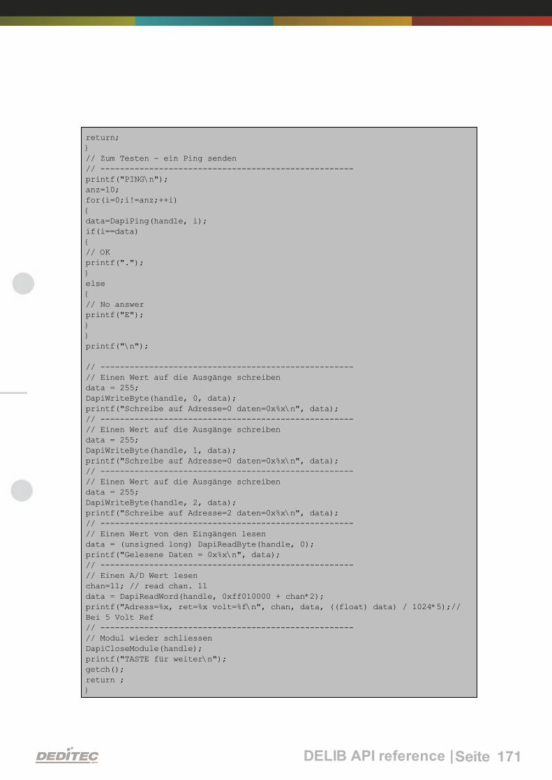
DELIB API reference |Seite 171
return;}// Zum Testen - ein Ping senden// ----------------------------------------------------printf("PING\n");anz=10;for(i=0;i!=anz;++i){data=DapiPing(handle, i);if(i==data){// OKprintf(".");}else{// No answerprintf("E");}}printf("\n");
// ----------------------------------------------------// Einen Wert auf die Ausgänge schreibendata = 255;DapiWriteByte(handle, 0, data);printf("Schreibe auf Adresse=0 daten=0x%x\n", data);// ----------------------------------------------------// Einen Wert auf die Ausgänge schreibendata = 255;DapiWriteByte(handle, 1, data);printf("Schreibe auf Adresse=0 daten=0x%x\n", data);// ----------------------------------------------------// Einen Wert auf die Ausgänge schreibendata = 255;DapiWriteByte(handle, 2, data);printf("Schreibe auf Adresse=2 daten=0x%x\n", data);// ----------------------------------------------------// Einen Wert von den Eingängen lesendata = (unsigned long) DapiReadByte(handle, 0);printf("Gelesene Daten = 0x%x\n", data);// ----------------------------------------------------// Einen A/D Wert lesenchan=11; // read chan. 11data = DapiReadWord(handle, 0xff010000 + chan*2);printf("Adress=%x, ret=%x volt=%f\n", chan, data, ((float) data) / 1024*5);//Bei 5 Volt Ref// ----------------------------------------------------// Modul wieder schliessenDapiCloseModule(handle);printf("TASTE für weiter\n");getch();return ;}

V
Appendix |Seite 172
Appendix

Appendix |Seite 173
5. Appendix
5.1. Revisions
Rev 1.00 First issue
Rev 1.01 Added flexible connector system
Revision of the block diagrams
Rev 1.1 Software installation
Rev 1.2 Added RO-AD16_ISO
Rev 1.3 Modification in configuration serial / CAN
Rev 1.4 Added Chapter stepper
Rev 1.5 Modification of section CAN interface settings
Rev 1.6 Modification of chapter 2.2.2.3
Rev 1.7 Added Ethernet-Interface
Rev 2.00 Design change
Rev 2.01 New stepper command
"DAPI_STEPPER_CMD_GO_POSITION_RELATIVE"
Supplement of return value for command
"DAPI_STEPPER_STATUS_GET_ACTIVITY"
Supplement of parameter hold-time (endless time)
for command
"DAPI_STEPPER_CMD_SET_MOTORCHARACTERISTIC"

Appendix |Seite 174
5.2. Copyrights and trademarks
Linux is registered trade-mark of Linus Torvalds.
Windows CE is registered trade-mark of Microsoft Corporation.
USB is registered trade-mark of USB Implementers Forum Inc.
LabVIEW is registered trade-mark of National Instruments.
Intel is registered trade-mark of Intel Corporation
AMD is registered trade-mark of Advanced Micro Devices, Inc.

DEDITEC Driver Library
Dezember
DELIB
2010

INDEX
Index | 2Seite
1. Welcome 7
2. Introduction 9
2.1. General remarks 9
2.2. Customer satisfaction 9
2.3. Customer response 9
3. Software 11
3.1. Using our products 11
113.1.1. Access via graphical applications 113.1.2. Access via the DELIB driver library 113.1.3. Access via protocol 123.1.4. Access via provided test programs
3.2. DELIB driver library 13
133.2.1. Overview 153.2.2. Supported operating systems 153.2.3. Supported programming languages 163.2.4. Installation DELIB driver library 183.2.5. DELIB Configuration Utility
3.3. Test programs 19
193.3.1. Digital Input-Output Demo 203.3.2. Analog Input-Output Demo 213.3.3. Stepper Demo
4. Directory structure of the DELIB 23
4.1. Include directory 23
4.2. Library-directory 23
4.3. Library-directory for Borland 23
4.4. Environment variables 24
5. DELIB API reference 26

INDEX
Index | 3Seite
5.1. Management functions 26
265.1.1. DapiOpenModule 275.1.2. DapiCloseModule
5.2. Error handling 28
285.2.1. DapiGetLastError 295.2.2. DapiGetLastErrorText
5.3. Reading Digital inputs 30
305.3.1. DapiDIGet1 315.3.2. DapiDIGet8 325.3.3. DapiDIGet16 335.3.4. DapiDIGet32 345.3.5. DapiDIGet64 355.3.6. DapiDIGetFF32 365.3.7. DapiDIGetCounter
5.4. Setting Digital outputs 37
375.4.1. DapiDOSet1 385.4.2. DapiDOSet8 395.4.3. DapiDOSet16 405.4.4. DapiDOSet32 415.4.5. DapiDOSet64 425.4.6. DapiDOReadback32 435.4.7. DapiDOReadback64
5.5. A/D converter functions 44
445.5.1. DapiADSetMode 465.5.2. DapiADGetMode 475.5.3. DapiADGet 485.5.4. DapiADGetVolt 495.5.5. DapiADGetmA
5.6. D/A outputs management 50
505.6.1. DapiDASetMode 525.6.2. DapiDAGetMode 535.6.3. DapiDASet 545.6.4. DapiDASetVolt 555.6.5. DapiDASetmA

INDEX
Index | 4Seite
565.6.6. DapiSpecialCmd_DA
5.7. Set TTL-In-/Outputs direction with DapiSpecialCommand 58
585.7.1. DAPI_SPECIAL_CMD_SET_DIR_DX_1 595.7.2. DAPI_SPECIAL_CMD_SET_DIR_DX_8
5.8. Stepper motor functions 60
605.8.1. DapiStepperCommands 605.8.1.1. DAPI_STEPPER_CMD_GO_POSITION
61
5.8.1.2.
DAPI_STEPPER_CMD_GO_POSITION_RELATIVE
625.8.1.3. DAPI_STEPPER_CMD_SET_POSITION
635.8.1.4. DAPI_STEPPER_CMD_SET_FREQUENCY
645.8.1.5. DAPI_STEPPER_CMD_GET_FREQUENCY
65
5.8.1.6.
DAPI_STEPPER_CMD_SET_FREQUENCY_DIRECTLY
665.8.1.7. DAPI_STEPPER_CMD_STOP
675.8.1.8. DAPI_STEPPER_CMD_FULLSTOP
685.8.1.9. DAPI_STEPPER_CMD_DISABLE
69
5.8.1.10.
DAPI_STEPPER_CMD_SET_MOTORCHARACTERISTIC
74
5.8.1.11.
DAPI_STEPPER_CMD_GET_MOTORCHARACTERISTIC
82
5.8.1.12.
DAPI_STEPPER_CMD_MOTORCHARACTERISTIC_EEP
ROM_SAVE
83
5.8.1.13.
DAPI_STEPPER_CMD_MOTORCHARACTERISTIC_EEP
ROM_LOAD
84
5.8.1.14.
DAPI_STEPPER_CMD_MOTORCHARACTERISTIC_LOA
D_DEFAULT
855.8.1.15. DAPI_STEPPER_CMD_GO_REFSWITCH
865.8.1.16. DAPI_STEPPER_CMD_GET_CPU_TEMP
87
5.8.1.17.
DAPI_STEPPER_CMD_GET_MOTOR_SUPPLY_VOLTAG
E
885.8.2. DapiStepperGetStatus 885.8.2.1. DAPI_STEPPER_STATUS_GET_ACTIVITY
895.8.2.2. DAPI_STEPPER_STATUS_GET_POSITION
905.8.2.3. DAPI_STEPPER_STATUS_GET_SWITCH
915.8.3. DapiStepperCommandEx

INDEX
Index | 5Seite
5.9. Output timeout management 92
925.9.1. DapiSpecialCMDTimeout 935.9.2. DapiSpecialCMDTimeoutGetStatus
5.10. Test functions 94
945.10.1. DapiPing
5.11. Register write commands 95
955.11.1. DapiWriteByte 965.11.2. DapiWriteWord 975.11.3. DapiWriteLong 985.11.4. DapiWriteLongLong
5.12. Register read commands 99
995.12.1. DapiReadByte 1005.12.2. DapiReadWord 1015.12.3. DapiReadLong 1025.12.4. DapiReadLongLong
5.13. Example program 103
6. Appendix 106
6.1. Revisions 106
6.2. Copyrights and trademarks 107

I
Welcome |Seite 6
Welcome

Welcome |Seite 7
1. Welcome
Manual
DELIB

II
Introduction |Seite 8
Introduction

Introduction |Seite 9
2. Introduction
2.1. General remarks
First of all, we would like to congratulate you to the purchase of a high qualityDEDITEC product.
Our products are being developed by our engineers according to qualityrequirements of high standard. Already during design and development we takecare that our products have -besides quality- a long availability and an optimalflexibility.
Modular design
The modular design of our products reduces the time and the cost ofdevelopment. Therefor we can offer you high quality products at a competitiveprice.
Availability
Because of the modular design of our products, we have to redesign only amodule instead of the whole product, in case a specific component is no longeravailable.
2.2. Customer satisfaction
Our philosophy: a content customer will come again. Therefor customersatisfaction is in first place for us.
If by any chance, you are not content with the performance of our product,please contact us by phone or mail immediately.
We take care of the problem.
2.3. Customer response
Our best products are co-developments together with our customers. Thereforwe are thankful for comments and suggestions.

III
Software |Seite 10
Software

Software |Seite 11
3. Software
3.1. Using our products
3.1.1. Access via graphical applications
We provide driverinterfaces e.g. for LabVIEW and ProfiLab. The DELIB driverlibrary is the basis, which can be directly activated by ProfiLAB.
For LabVIEW, we provide a simple driver connection with examples!
3.1.2. Access via the DELIB driver library
In the appendix, you can find the complete function reference for the integrationof our API-functions in your software. In addition we provide examples for thefollowing programming languages:
C
C++
C#
Delphi
VisualBasic
VB.NET
MS-Office
3.1.3. Access via protocol
The protocol for the activation of our products is open source. So you are ableto use our products on systems without Windows or Linux.

Software |Seite 12
3.1.4. Access via provided test programs
We provide simple handling test programs for the most important functions ofour products. These will be installed automatically by the installation of theDELIB driver library.
So you can test directly e.g. relays or you can check the voltage of an A/Dconverter.

Software |Seite 13
3.2. DELIB driver library
3.2.1. Overview
The following figure explains the structure of the DELIB driver library
The DELIB driver library allows an uniform response of DEDITEC hardware withparticular consideration of the following viewpoints:
Independent of operating system
Independent of programming language
Independent of the product
Program under diverse operating systems
The DELIB driver library allows an uniform response of our products on diverseoperating systems.
We has made sure, that all of our products can be responded by a fewcommands.Whatever which operating system you use. - Therefore the DELIB cares!

Software |Seite 14
Program with diverse programming languages
We provide uniform commands to create own applications. This will be solvedby the DELIB driver library.
You choose the programming language!
It can be simply developed applications under C++, C, Visual Basic, Delphi orLabVIEW®.
Program independent of the interface
Write your application independent of the interface !
Program an apllication for an USB product of us. - Also, it will work with anethernet or RS-232 product of us !
SDK-Kit for Programmer
Integrate the DELIB in your application. On demand you receive an installationscript for free, which allows you, to integrate the DELIB installation in yourapllication.

Software |Seite 15
3.2.2. Supported operating systems
Our products support the following operating systems:
Windows 2000
Windows XP
Windows Vista
Windows 7
Linux
3.2.3. Supported programming languages
Our products are responsive via the following programming languages:
C
C++
C#
Delphi
VisualBasic
VB.NET
MS-Office

Software |Seite 16
3.2.4. Installation DELIB driver library
DELIB stands for DEDITEC Library and contains the necessary libraries for themodules in the programming languages C, Delphi and Visual Basic.
Insert the DEDITEC driver CD into the drive and start „delib_install.exe“. The
DELIB driver library is also available on http://www.deditec.en/delib
Click on „Install“.

Software |Seite 17
The drivers will be installed.
The DELIB driver library is now installed. Press „Close“ to finish the installation.
You can configure your module with the „DELIB Configuration Utility“ (see
next chapter). This is only necessary, if more than one module is present.

Software |Seite 18
3.2.5. DELIB Configuration Utility
Start the “DELIB Configuration Utility” as follows:
Start Programs DEDITEC DELIB DELIB Configuration Utility.
The „DELIB Configuration Utility“ is a program to configure and subdivide
identical USB-modules in the system. This is only necessary if more than onemodule is present.

Software |Seite 19
3.3. Test programs
3.3.1. Digital Input-Output Demo
Start “Digital Input-Output Demo” as follows:
Start Programme DEDITEC DELIB Digital Input-Output Demo.
The screenshot shows a test of the RO-USB-O64-R64. The configuration of themodule (64 inputs and 64 outputs) is shown on the upper left side.

Software |Seite 20
3.3.2. Analog Input-Output Demo
Start “Analog Input-Output Demo” as follows:
Start Programme DEDITEC DELIB Analog Input-Output Demo.
The screenshot shows a test of the RO-USB-AD16-DA2_ISO. The configurationof the module (16 A/D inputs and 2 D/A outputs) is shown on the upper left side.

Software |Seite 21
3.3.3. Stepper Demo
Start “Stepper Demo” as follows:
Start Programme DEDITEC DELIB Stepper Demo.
The screenshot shows a test of the RO-USB-STEPPER2. The configuration ofthe module (2 Stepper) is shown on the upper left side.

IV
Directory structure of the DELIB |Seite 22
Directory structure of the DELIB

Directory structure of the DELIB |Seite 23
4. Directory structure of the DELIB
After successful installation the following directory tree is shown:
C:\Programs\DEDITEC\DELIB\
> include Includes for programming language ( chapter 3.1.1)
> lib Library ( chapter 3.1.2)
> lib\bc Borland Compiler Library ( chapter 3.1.2)
> programs Module -testprogramms ( chapter 2.3)
> USB-Driver Driver for USB modules
Further, files like delib.dll and miscellaneous USB system driver have beeninstalled to C:\WINNT\system32\.
4.1. Include directory
The include directory of the DELIB contains the files, which are used for thelibrary functions. They are given for the programming language C (.h), Delphi (.pas) and Visual Basic (.bas).
4.2. Library-directory
Here you can find the file "DELIB.lib". It is used as link for compiling of own
programs, that use the "DELIB.dll".
4.3. Library-directory for Borland
For Borland compiler exists a separate DELIB.lib, that is in the subdirectory "bc
". This is also used as link for compiling of own programs, that use the "DELIB.
dll".

Directory structure of the DELIB |Seite 24
4.4. Environment variables
Two environment variables point to important directories, that contain the filesfor the programming language C, Delphi and Visual Basic.
“DELIB_INCLUDE” points to the include-directory
%DELIB_INCLUDE% c:\Programs\DEDITEC\DELIB\include"
“DELIB_LIB” points to the library-directory
%DELIB_LIB% c:\ Programs\DEDITEC\DELIB\lib

V
DELIB API reference |Seite 25
DELIB API reference

DELIB API reference |Seite 26
5. DELIB API reference
5.1. Management functions
5.1.1. DapiOpenModule
Description
This function opens a particular module.
Definition
ULONG DapiOpenModule(ULONG moduleID, ULONG nr);
Parameters
moduleID=Specifies the module, which is to be opened (see delib.h)
nr=Indicates No of module which is to be opened.
nr=0 -> 1. module
nr=1 -> 2. module
Return value
handle=handle to the corresponding module
handle=0 -> Module was not found
Remarks
The handle returned by this function is needed to identify the module for allother functions.
Example program
// USB-Modul öffnenhandle = DapiOpenModule(RO_USB1, 0);printf("handle = %x\n", handle);if (handle==0){// USB Modul wurde nicht gefundenprintf("Modul konnte nicht geöffnet werden\n");return;}

DELIB API reference |Seite 27
5.1.2. DapiCloseModule
Description
This command closes an opened module.
Definition
ULONG DapiCloseModule(ULONG handle);
Parameters
handle=This is the handle of an opened module
Return value
none
Example program
// Close the moduleDapiCloseModule(handle);

DELIB API reference |Seite 28
5.2. Error handling
5.2.1. DapiGetLastError
Description
This function returns the last registered error.
Definition
ULONG DapiGetLastError();
Parameters
None
Return value
Error code
0=no error. (see delib.h)
Example program
ULONG error;error=DapiGetLastError();if(error==0) return FALSE;printf("ERROR = %d", error);

DELIB API reference |Seite 29
5.2.2. DapiGetLastErrorText
Description
This function reads the text of the last registered error.
Definition
extern ULONG __stdcall DapiGetLastErrorText(unsigned char * msg, unsigned longmsg_length);
Parameters
msg = text buffer
msg_length = length of the buffer
Example program
BOOL IsError (){ if (DapiGetLastError () != DAPI_ERR_NONE)
{ unsigned char msg[500];
DapiGetLastErrorText((unsigned char*) msg, sizeof(msg)); printf ("Error Code = %x * Message = %s\n", 0, msg); return TRUE;}
return FALSE;}

DELIB API reference |Seite 30
5.3. Reading Digital inputs
5.3.1. DapiDIGet1
Description
This command reads a single digit input.
Definition
ULONG DapiDIGet1(ULONG handle, ULONG ch);
Parameters
handle=This is the handle of an opened module.
ch=Specifies the number of input that is to be read (0 ..).
Return value
State of the input (0 / 1).

DELIB API reference |Seite 31
5.3.2. DapiDIGet8
Description
This command reads 8 digital inputs simultaneously.
Definition
ULONG DapiDIGet8(ULONG handle, ULONG ch);
Parameters
handle=This is the handle of an opened module.
ch=Specifies the number of the input, from which it begins to read from (0, 8,16, 24, 32, ..)
Return value
State of the read inputs.

DELIB API reference |Seite 32
5.3.3. DapiDIGet16
Description
This command reads 16 digital inputs simultaneously.
DefinitionULONG DapiDIGet16(ULONG handle, ULONG ch);
Parameters
handle=This is the handle of an opened module.
ch=Specifies the number of the input, from which it begins to read from (0, 16,32, ..)
Return value
State of the read inputs.

DELIB API reference |Seite 33
5.3.4. DapiDIGet32
Description
This command reads 32 digital inputs simultaneously.
Definition
ULONG DapiDIGet32(ULONG handle, ULONG ch);
Parameters
handle=This is the handle of an opened module.
ch=Specifies the number of the input, from which it begins to read from (0, 32,64, ..)
Return value
State of the read inputs.
Example program
unsigned long data;// ----------------------------------------------------// Einen Wert von den Eingängen lesen (Eingang 1-31)data = (unsigned long) DapiDIGet32(handle, 0);// Chan Start = 0printf("Eingang 0-31 : 0x%x\n", data);printf("Taste für weiter\n");getch();// ----------------------------------------------------// Einen Wert von den Eingängen lesen (Eingang 32-64)data = (unsigned long) DapiDIGet32(handle, 32);// Chan Start = 32printf("Eingang 32-64 : 0x%x\n", data);printf("Taste für weiter\n");getch();

DELIB API reference |Seite 34
5.3.5. DapiDIGet64
Description
This command reads 64 digital inputs simultaneously.
Definition
ULONGLONG DapiDIGet64(ULONG handle, ULONG ch);
Parameters
handle=This is the handle of an opened module.
ch=Specifies the number of the input,from which it begins to read from (0, 64, ..)
Return value
State of the read inputs.

DELIB API reference |Seite 35
5.3.6. DapiDIGetFF32
Description
This command reads the flip-flops from the inputs and resets them. (Input statechange).
Definition
ULONG DapiDIGetFF32(ULONG handle, ULONG ch);
Parameters
handle=This is the handle of an opened module .
ch=Specifies the number of the input, from which it begins to read from (0, 32,..)
Return value
State of 32 input change states

DELIB API reference |Seite 36
5.3.7. DapiDIGetCounter
Description
This command reads the counter of a digital input
Definition
ULONG DapiDIGetCounter(handle, ch, par1);
Parameters
handle=This is the handle of an opened module.
ch=Specifies the digital input, from which the counter will be read
par1=0 (Normal counter function)
par1=DAPI_CNT_MODE_READ_WITH_RESET (Reading and resetting thecounter)
Return value
Value of the counter.
Example program
value = DapiDIGetCounter(handle, 0 ,0);// Reading counter of DI Chan 0
value = DapiDIGetCounter(handle, 1 ,0);// Reading counter of DI Chan 1
value = DapiDIGetCounter(handle, 8 ,0);// Reading counter of DI Chan 8
value = DapiDIGetCounter(handle, 0 ,DAPI_CNT_MODE_READ_WITH_RESET);// Reading AND resetting counter of DI Chan 0

DELIB API reference |Seite 37
5.4. Setting Digital outputs
5.4.1. DapiDOSet1
Description
This is the command to set a single output.
Definition
void DapiDOSet1(ULONG handle, ULONG ch, ULONG data);
Parameters
handle=This is the handle of an opened module
ch=Specifies the number of the output to be set to (0 ..)
data=Specifies the data value that is to be written (0 / 1)
Return value
None

DELIB API reference |Seite 38
5.4.2. DapiDOSet8
Description
This command sets 8 digital outputs simultaneously.
Definition
void DapiDOSet8(ULONG handle, ULONG ch, ULONG data);
Parameters
handle=This is the handle of an opened module
ch=Specifies the number of the output, from which it begins to write to (0, 8, 16,24, 32, ..)
data=Specifies the data values, to write to the outputs
Return value
None

DELIB API reference |Seite 39
5.4.3. DapiDOSet16
Description
This command sets 16 digital outputs simultaneously.
Definition
void DapiDOSet16(ULONG handle, ULONG ch, ULONG data);
Parameters
handle=This is the handle of an opened module
ch=Specifies the number of the output, from which it begins to write to (0, 16,32, ..)
data=Specifies the data values, to write to the outputs
Return value
None

DELIB API reference |Seite 40
5.4.4. DapiDOSet32
Description
This command sets 32 digital outputs simultaneously.
Definition
void DapiDOSet32(ULONG handle, ULONG ch, ULONG data);
Parameters
handle=This is the handle of an opened module
ch=Specifies the number of the output, from which it begins to write to (0, 32,64, ..)
data=Specifies the data values, to write to the outputs
Return value
None
Example program
// Einen Wert auf die Ausgänge schreibendata = 0x0000ff00; // Ausgänge 9-16 werden auf 1 gesetztDapiDOSet32(handle, 0, data); // Chan Start = 0printf("Schreibe auf Ausgänge Daten=0x%x\n", data);printf("Taste für weiter\n");getch();// ----------------------------------------------------// Einen Wert auf die Ausgänge schreibendata = 0x80000000; // Ausgang 32 wird auf 1 gesetztDapiDOSet32(handle, 0, data); // Chan Start = 0printf("Schreibe auf Ausgänge Daten=0x%x\n", data);printf("Taste für weiter\n");getch();// ----------------------------------------------------// Einen Wert auf die Ausgänge schreibendata = 0x80000000; // Ausgang 64 wird auf 1 gesetztDapiDOSet32(handle, 32, data); // Chan Start = 32printf("Schreibe auf Ausgänge Daten=0x%x\n", data);printf("Taste für weiter\n");getch();

DELIB API reference |Seite 41
5.4.5. DapiDOSet64
Description
This command is to set 64 digital outputs.
Definition
void DapiDOSet64(ULONG handle, ULONG ch, ULONG data);
Parameters
handle=This is the handle of an opened module
ch=Specifies the number of the output, from which it begins to write to (0, 64, ..)
data=Specifies the data values, to write to the outputs
Return value
None

DELIB API reference |Seite 42
5.4.6. DapiDOReadback32
Description
This command reads back the 32 digital outputs.
Definition
ULONG DapiDOReadback32(ULONG handle, ULONG ch);
Parameters
handle=This is the handle of an opened module
ch=Specifies the number of the input, from which it begins to read from (0, 32,..)
Return value
Status of 32 outputs.

DELIB API reference |Seite 43
5.4.7. DapiDOReadback64
Description
This command reads back the 64 digital outputs.
Definition
ULONGLONG DapiDOReadback64(ULONG handle, ULONG ch);
Parameters
handle=This is the handle of an opened module
ch=Specifies the number of the input, from which it begins to read from (0, 64,..)
Return value
Status of 64 outputs.

DELIB API reference |Seite 44
5.5. A/D converter functions
5.5.1. DapiADSetMode
Description
This is the command to configure the input range of an A/D converter.
Definition
void DapiADSetMode(ULONG handle, ULONG ch, ULONG mode);
Parameters
handle=This is the handle of an opened module
ch=Specifies the channel of the A/D converter (0 ..)
mode=Specifies the mode for the channel
Return value
None
Remarks
The following modes are supported:
(these are dependent on the A/D module)
Unipolar voltages:
ADDA_MODE_UNIPOL_10V
ADDA_MODE_UNIPOL_5V
ADDA_MODE_UNIPOL_2V5
Bipolar voltages:
ADDA_MODE_BIPOL_10V
ADDA_MODE_BIPOL_5V
ADDA_MODE_BIPOL_2V5

DELIB API reference |Seite 45
Currents:
ADDA_MODE_0_20mA
ADDA_MODE_4_20mA
ADDA_MODE_0_24mA
ADDA_MODE_0_25mA
ADDA_MODE_0_50mA

DELIB API reference |Seite 46
5.5.2. DapiADGetMode
Description
This command reads the set mode of an A/D converter. For mode descriptionsee DapiADSetMode.
Definition
ULONG DapiADGetMode(ULONG handle, ULONG ch);
Parameters
handle=This is the handle of an opened module
ch=Specifies the channel of the A/D converter (0 ..)
Return value
Mode of the A/D converter

DELIB API reference |Seite 47
5.5.3. DapiADGet
Description
This command reads a data value of one channel of an A/D converter
Definition
ULONG DapiADGet(ULONG handle, ULONG ch);
Parameters
handle=This is the handle of an opened module
ch=Specifies the channel of the A/D converter (0 ..)
Return value
Value from the A/D converter in Digits

DELIB API reference |Seite 48
5.5.4. DapiADGetVolt
Description
This command reads a data value of one channel of an A/D converter in volts.
Definition
float DapiADGetVolt(ULONG handle, ULONG ch);
Parameters
handle=This is the handle of an opened module
ch=Specifies the channel of the A/D converter (0 ..)
Return value
Value from the A/D converter in volts

DELIB API reference |Seite 49
5.5.5. DapiADGetmA
Description
This command reads a data value of one channel of an A/D converter in mA.
Definition
float DapiADGetmA(ULONG handle, ULONG ch);
Parameters
handle=This is the handle of an opened module
ch=Specifies the channel of the A/D converter (0 ..)
Return value
Value from the A/D converter in mA.
Remarks
This command is module dependent. It only works if the module also supportsthe current mode.

DELIB API reference |Seite 50
5.6. D/A outputs management
5.6.1. DapiDASetMode
Description
This command sets the mode for a D/A converter.
Definition
void DapiDASetMode(ULONG handle, ULONG ch, ULONG mode);
Parameters
handle=This is the handle of an opened module
ch=Specifies the channel of the D/A converter (0 ..)
mode=Specifies the mode of the D/A converter
Return value
None
Remarks
The following modes are supported:
(these are dependent on the used D/A module)
Unipolar voltages:
ADDA_MODE_UNIPOL_10V
ADDA_MODE_UNIPOL_5V
ADDA_MODE_UNIPOL_2V5
Bipolar voltages:
ADDA_MODE_BIPOL_10V
ADDA_MODE_BIPOL_5V
ADDA_MODE_BIPOL_2V5

DELIB API reference |Seite 51
Currents:
ADDA_MODE_0_20mA
ADDA_MODE_4_20mA
ADDA_MODE_0_24mA
ADDA_MODE_0_25mA
ADDA_MODE_0_50mA

DELIB API reference |Seite 52
5.6.2. DapiDAGetMode
Description
This command reads back the chosen mode of a D/A converter.
Definition
ULONG DapiDAGetMode(ULONG handle, ULONG ch);
Parameters
handle=This is the handle of an opened module
ch=Specifies the channel of the D/A converter (0 ..)
Return value
Mode of the D/A converter

DELIB API reference |Seite 53
5.6.3. DapiDASet
Description
This command transfers a data value to a channel of a D/A converter.
Definition
void DapiDASet(ULONG handle, ULONG ch, ULONG data);
Parameters
handle=This is the handle of an opened module
ch=Specifies the channel of the D/A converter (0 ..)
data=Specifies the data value, which is written
Return value
None

DELIB API reference |Seite 54
5.6.4. DapiDASetVolt
Description
This command sets a voltage to a channel of a D/A converter.
Definition
void DapiDASetVolt(ULONG handle, ULONG ch, float data);
Parameters
handle=This is the handle of an opened module
ch=Specifies the channel of the D/A converter (0 ..)
data=the voltage, which is to be set [V]
Return value
None

DELIB API reference |Seite 55
5.6.5. DapiDASetmA
Description
This command sets a current to a channel of a D/A converter.
Definition
void DapiDASetmA(ULONG handle, ULONG ch, float data);
Parameters
handle=This is the handle of an opened module
ch=Specifies the channel of the D/A converter (0 ..)
data=Specifies the current, which is to be set [mA]
Return value
None
Remarks
This command depends on the module. It only works, if the module alsosupports the current mode.

DELIB API reference |Seite 56
5.6.6. DapiSpecialCmd_DA
Description
This command sets the voltage/current value to a D/A channel at powering up orafter a timeout. (EEPROM Configuration)
Definition
void DapiSpecialCommand(handle, DAPI_SPECIAL_CMD_DA, cmd, ch, 0);
Parameters
handle=This is the handle of an opened module
ch=Specifies the channel of the D/A converter (0, 1, 2, ..)
Reset settings to default configuration
cmd=DAPI_SPECIAL_DA_PAR_DA_LOAD_DEFAULT
Save configuration to EEPROM
cmd=DAPI_SPECIAL_DA_PAR_DA_SAVE_EEPROM_CONFIG
Load configuration out of EEPROM
cmd=DAPI_SPECIAL_DA_PAR_DA_LOAD_EEPROM_CONFIG
Return value
None
Remarks
DAPI_SPECIAL_CMD_DA_PAR_DA_LOAD_DEFAULT
This command loads the default configuration of a D/A converter. The D/Aoutput has the voltage 0V now.
DAPI_SPECIAL_DA_PAR_DA_SAVE_EEPROM_CONFIG
This command saves the current settings of the D/A converter (voltage/currentvalue, enable/disable and D/A converter mode) to EEPROM.
DAPI_SPECIAL_DA_PAR_DA_LOAD_EEPROM_CONFIG
This command sets the saved EEPROM configuration to the D/A converter.

DELIB API reference |Seite 57
Example program
DapiSpecialCommand(handle, DAPI_SPECIAL_CMD_DA,DAPI_SPECIAL_DA_PAR_DA_LOAD_DEFAULT, 1, 0); //Zurücksetzen der EEPROM-Konfiguration auf Default Konfiguration bei Kanal 1.
DapiSpecialCommand(handle, DAPI_SPECIAL_CMD_DA,DAPI_SPECIAL_DA_PAR_DA_SAVE_EEPROM_CONFIG, 3, 0); //Speichern der D/AWandler Einstellungen in das EEPROM bei Kanal 3.
DapiSpecialCommand(handle, DAPI_SPECIAL_CMD_DA,DAPI_SPECIAL_DA_PAR_DA_LOAD_EEPROM_CONFIG, 2, 0); //Setzen des D/A Wandlers,mit der im EEPROM gespeicherten Konfiguration bei Kanal 2.

DELIB API reference |Seite 58
5.7. Set TTL-In-/Outputs direction with DapiSpecialCommand
5.7.1. DAPI_SPECIAL_CMD_SET_DIR_DX_1
Description
This command sets the direction of the TTL-In/Outputs (1-Bit).
Definition
void DapiSpecialCommand(ULONG handle, DAPI_SPECIAL_CMD_SET_DIR_DX_1,ULONG ch, ULONG dir, 0);
Parameters
handle=This is the handle of an opened module.
ch=Specifies the number of the output, from which the direction should be set(0, 8, 16, 24..)
dir=Specifies the direction for 8 channels (1=output / 0=input) / Bit 0 signifieschannel 0, Bit 1 channel 1 ...
Example program
DapiSpecialCommand(handle, DAPI_SPECIAL_CMD_SET_DIR_DX_1, 0, 0x01 , 0);// Set Dir of TTL-I/O CH0 to output, others to inputDapiSpecialCommand(handle, DAPI_SPECIAL_CMD_SET_DIR_DX_1, 0, 0x02 , 0);// Set Dir of TTL-I/O CH1 to output, others to inputDapiSpecialCommand(handle, DAPI_SPECIAL_CMD_SET_DIR_DX_1, 0, 0x04 , 0);// Set Dir of TTL-I/O CH2 to output, others to inputDapiSpecialCommand(handle, DAPI_SPECIAL_CMD_SET_DIR_DX_1, 0, 0x08 , 0);// Set Dir of TTL-I/O CH3 to output, others to inputDapiSpecialCommand(handle, DAPI_SPECIAL_CMD_SET_DIR_DX_1, 0, 0x10 , 0);// Set Dir of TTL-I/O CH4 to output, others to inputDapiSpecialCommand(handle, DAPI_SPECIAL_CMD_SET_DIR_DX_1, 0, 0x20 , 0);// Set Dir of TTL-I/O CH5 to output, others to inputDapiSpecialCommand(handle, DAPI_SPECIAL_CMD_SET_DIR_DX_1, 0, 0x40 , 0);// Set Dir of TTL-I/O CH6 to output, others to inputDapiSpecialCommand(handle, DAPI_SPECIAL_CMD_SET_DIR_DX_1, 0, 0x80 , 0);// Set Dir of TTL-I/O CH7 to output, others to input
DapiSpecialCommand(handle, DAPI_SPECIAL_CMD_SET_DIR_DX_1, 0, 0x0f , 0);// Set Dir of TTL-I/O CH0-3 to output, others to inputDapiSpecialCommand(handle, DAPI_SPECIAL_CMD_SET_DIR_DX_1, 0, 0xff , 0);// Set Dir of TTL-I/O CH0-7 to output, others to input

DELIB API reference |Seite 59
5.7.2. DAPI_SPECIAL_CMD_SET_DIR_DX_8
Description
This command sets the direction of the TTL-In/Outputs (8-Bit way).
Definition
void DapiSpecialCommand(ULONG handle, DAPI_SPECIAL_CMD_SET_DIR_DX_8,ULONG ch, ULONG dir, 0);
Parameters
handle=This is the handle of an opened module.
ch=Specifies the number of the output,from which the direction will be set (0, 8,16, 24 ..). Values between are invalid.
dir=(8-Bit) gives the direction for 8 In/Outputs. (1=output / 0=input)
Example program
DapiSpecialCommand(handle, DAPI_SPECIAL_CMD_SET_DIR_DX_8, 0, 1, 0);
// Set Dir of TTL-I/O CH0 to out

DELIB API reference |Seite 60
5.8. Stepper motor functions
5.8.1. DapiStepperCommands
5.8.1.1. DAPI_STEPPER_CMD_GO_POSITION
Description
With this command the motor will drive to a position. This command can only beused when the motor is not disabled and Go_Position or Go_Reference are notexecuted.
Definition
DapiStepperCommand(handle, motor, DAPI_STEPPER_CMD_GO_POSITION,position, 0, 0, 0);
Example program
DapiStepperCommand(handle, motor, DAPI_STEPPER_CMD_GO_POSITION , go_pos_par,0,0,0);

DELIB API reference |Seite 61
5.8.1.2. DAPI_STEPPER_CMD_GO_POSITION_RELATIVE
Description
With this command the motor will go to a relative position. In contrast to thecommand GO_POSITION, which goes to an absolute position, this commandconsiders the current position. This command can only be used when the motoris not disabled and Go_Position or Go_Reference are not executed.
Definition
void DapiStepperCommand(handle, motor,DAPI_STEPPER_CMD_GO_POSITION_RELATIVE, go_pos_rel_par, 0, 0, 0);
Parameters
go_pos_rel_par=the relative position, to which will be gone
Example program
DapiStepperCommand(handle, motor, DAPI_STEPPER_CMD_GO_POSITION_RELATIVE, 100,0, 0, 0);//Motor fährt, von der aktuellen Position aus gesehen, 100 Schritte nachrechts.

DELIB API reference |Seite 62
5.8.1.3. DAPI_STEPPER_CMD_SET_POSITION
Description
This command ist used to set the motor position. The resolution ist 1/16 Full-step. This command may be used anytime.
Definition
DapiStepperCommand(handle, motor, DAPI_STEPPER_CMD_SET_POSITION, par1,0, 0, 0);
Parameters
par1=Motor position

DELIB API reference |Seite 63
5.8.1.4. DAPI_STEPPER_CMD_SET_FREQUENCY
Description
This command is used to set the motor reference frequency. The motorfrequency regulation takes on the compliance of the acceleration anddeceleration slope. Step losses do not occur. The motor reference frequency isrelated to the full-step-mode.
The direction will be defined by the prefix. If the motor reference frequency ishigher than the maximum frequency, the command is ignored.
With closed Endswitch1 the motor can only drive in positive direction, withclosed Endswitch2 the motor can only drive in negative direction, otherwise thecommand is ignored.
Definition
DapiStepperCommand(handle, motor, DAPI_STEPPER_CMD_SET_FREQUENCY,par1, 0, 0, 0);
Parameters
par1=Motor reference frequency [Hz]

DELIB API reference |Seite 64
5.8.1.5. DAPI_STEPPER_CMD_GET_FREQUENCY
Description
This command is used to read the motor frequency. This command can be usedeverytime.
Definition
DapiStepperCommand(handle, motor, DAPI_STEPPER_CMD_GET_FREQUENCY,par1, 0 ,0 ,0);
Return value
Motor frequency [Hz]

DELIB API reference |Seite 65
5.8.1.6. DAPI_STEPPER_CMD_SET_FREQUENCY_DIRECTLY
Description
This command is used to set the motor frequency. The motor frequencyregulation takes no funktion on the compliance of the acceleration anddeceleration slope. The user is responsible. Step losses can occur. The motorreference frequency is related to the full-step. The direction can be defined bythe prefix.
The motor frequency can't exceed the maximum frequency.
Definition
DapiStepperCommand(handle, motor,DAPI_STEPPER_CMD_SET_FREQUENCY_DIRECTLY, par1, 0 ,0 ,0);
Parameters
par1=Motor frequency [Hz]

DELIB API reference |Seite 66
5.8.1.7. DAPI_STEPPER_CMD_STOP
Description
This command is used to stop the motor, the deceleration slope will be used.
Definition
DapiStepperCommand(handle, motor, DAPI_STEPPER_CMD_STOP, 0, 0, 0, 0);

DELIB API reference |Seite 67
5.8.1.8. DAPI_STEPPER_CMD_FULLSTOP
Description
This command is used to stop the motors immediately without using the thedeceleration slope. After this command the motor position might be ignorredbecause the motor has been stopped uncontrolled.
Definition
DapiStepperCommand(handle, motor, DAPI_STEPPER_CMD_FULLSTOP, 0, 0, 0, 0);
Example program
DapiStepperCommand(handle, motor, DAPI_STEPPER_CMD_FULLSTOP , 0, 0, 0, 0);

DELIB API reference |Seite 68
5.8.1.9. DAPI_STEPPER_CMD_DISABLE
Description
This command is used to disable/enable the motor. The motor stops or startsdriving. This command can be only used when the motor stopped.
Definition
DapiStepperCommand(handle, motor, DAPI_STEPPER_CMD_DISABLE, par1, 0, 0,0);
Parameters
par1 = Disablemode (0=Normal function / 1=Disable)

DELIB API reference |Seite 69
5.8.1.10. DAPI_STEPPER_CMD_SET_MOTORCHARACTERISTIC
Description
With this command, you can set motor characteristics.
Definition
DapiStepperCommand(handle, motor,DAPI_STEPPER_CMD_SET_MOTORCHARACTERISTIC, par1, par2, 0, 0);
Parameters
Set Parameter-Stepmode
par1=DAPI_STEPPER_MOTORCHAR_PAR_STEPMODE
par2=0 (Full-step)
par2=1 (1/2-step)
par2=2 (1/4-step)
par2=3 (1/8-step)
par2=4 (1/16-step)
Set Parameter-GO-Frequency
par1=DAPI_STEPPER_MOTORCHAR_PAR_GOFREQUENCY
par2=Speed [Full-step / s] - related to full-step frequency - (maximumvalue=5000)
Set Parameter-Start-Frequency
par1=DAPI_STEPPER_MOTORCHAR_PAR_STARTFREQUENCY
par2=Startfrequency [Full-step / s] - related to full-step frequency - (maximumvalue=5000)
Set Parameter-Stop-Frequency
par1=DAPI_STEPPER_MOTORCHAR_PAR_STOPFREQUENCY
par2=Stopfrequency [Full-step / s] - related to full-step frequency - (maximumvalue=5000)
Set Parameter-Max-Frequency
par1=DAPI_STEPPER_MOTORCHAR_PAR_MAXFREQUENCY
par2=maximum frequency [Full-step / s] - related to full-step frequency -(maximum value=5000)
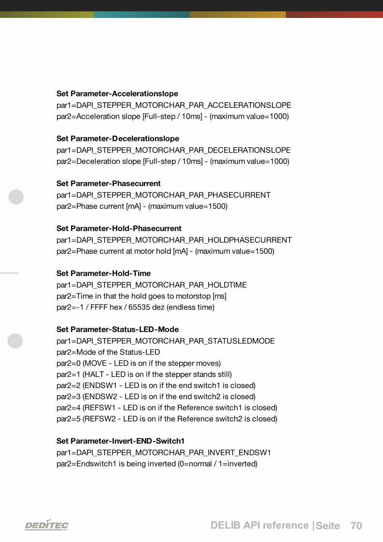
DELIB API reference |Seite 70
Set Parameter-Accelerationslope
par1=DAPI_STEPPER_MOTORCHAR_PAR_ACCELERATIONSLOPE
par2=Acceleration slope [Full-step / 10ms] - (maximum value=1000)
Set Parameter-Decelerationslope
par1=DAPI_STEPPER_MOTORCHAR_PAR_DECELERATIONSLOPE
par2=Deceleration slope [Full-step / 10ms] - (maximum value=1000)
Set Parameter-Phasecurrent
par1=DAPI_STEPPER_MOTORCHAR_PAR_PHASECURRENT
par2=Phase current [mA] - (maximum value=1500)
Set Parameter-Hold-Phasecurrent
par1=DAPI_STEPPER_MOTORCHAR_PAR_HOLDPHASECURRENT
par2=Phase current at motor hold [mA] - (maximum value=1500)
Set Parameter-Hold-Time
par1=DAPI_STEPPER_MOTORCHAR_PAR_HOLDTIME
par2=Time in that the hold goes to motorstop [ms]
par2=-1 / FFFF hex / 65535 dez (endless time)
Set Parameter-Status-LED-Mode
par1=DAPI_STEPPER_MOTORCHAR_PAR_STATUSLEDMODE
par2=Mode of the Status-LED
par2=0 (MOVE - LED is on if the stepper moves)
par2=1 (HALT - LED is on if the stepper stands still)
par2=2 (ENDSW1 - LED is on if the end switch1 is closed)
par2=3 (ENDSW2 - LED is on if the end switch2 is closed)
par2=4 (REFSW1 - LED is on if the Reference switch1 is closed)
par2=5 (REFSW2 - LED is on if the Reference switch2 is closed)
Set Parameter-Invert-END-Switch1
par1=DAPI_STEPPER_MOTORCHAR_PAR_INVERT_ENDSW1
par2=Endswitch1 is being inverted (0=normal / 1=inverted)

DELIB API reference |Seite 71
Set Parameter-Invert-END-Switch2
par1=DAPI_STEPPER_MOTORCHAR_PAR_INVERT_ENDSW2
par2=Endswitch2 is being inverted (0=normal / 1=inverted)
Set Parameter-Invert-Ref-Switch1
par1=DAPI_STEPPER_MOTORCHAR_PAR_INVERT_REFSW1
par2=Referenzswitch1 is being inverted (0=normal / 1=inverted)
Set Parameter-Invert-Ref-Switch2
par1=DAPI_STEPPER_MOTORCHAR_PAR_INVERT_REFSW2
par2=Referenzswitch2 is being inverted (0=normal / 1=inverted)
Set Parameter-Invert-direction
par1=DAPI_STEPPER_MOTORCHAR_PAR_INVERT_DIRECTION
par2=invert all direction details (0=normal / 1=inverted)
Set Parameter-Endswitch-Stopmode
par1= DAPI_STEPPER_MOTORCHAR_PAR_ENDSWITCH_STOPMODE
par2=setting of the stop behaviour (0=Fullstop / 1=Stop)
Set Parameter-GoReferenceFrequency (WARNING: This parameter will not
be supported anymore)
par1=DAPI_STEPPER_MOTORCHAR_PAR_GOREFERENCEFREQUENCY
Remark: This parameter is replaced completely by the following threeparameters.
Set Parameter-GoReferenceFrequnecyToEndSwitch
par1=DAPI_STEPPER_MOTORCHAR_PAR_GOREFERENCEFREQUENCY_TOENDSWITCH
par2=frequency [Full-step / s] - (maximum value=5000)
Set Parameter-GoReferenceFrequencyAfterEndSwitch
par1=DAPI_STEPPER_MOTORCHAR_PAR_GOREFERENCEFREQUENCY_AFTERENDSWITCH
par2=frequency [Full-step / s] - (maximum value=5000)

DELIB API reference |Seite 72
Set Parameter-GoReferenceFrequencyToOffSet
par1=DAPI_STEPPER_MOTORCHAR_PAR_GOREFERENCEFREQUENCY_TOOFFSET
par2=frequency [Full-step / s] - (maximum value=5000)
Example program
DapiStepperCommand(handle, motor, DAPI_STEPPER_CMD_SET_MOTORCHARACTERISTIC,DAPI_STEPPER_MOTORCHAR_PAR_STEPMODE, 4,0,0); // Schrittmode (Voll-, Halb-, Viertel-, Achtel-, Sechszehntelschritt)
DapiStepperCommand(handle, motor, DAPI_STEPPER_CMD_SET_MOTORCHARACTERISTIC,DAPI_STEPPER_MOTORCHAR_PAR_GOFREQUENCY, 1000,0,0);// Schrittmode (Voll-, Halb-, Viertel-, Achtel-, Sechszehntelschritt)
DapiStepperCommand(handle, motor, DAPI_STEPPER_CMD_SET_MOTORCHARACTERISTIC,DAPI_STEPPER_MOTORCHAR_PAR_STARTFREQUENCY, 100,0,0); // Startfrequenz [Vollschritt / s]
DapiStepperCommand(handle, motor, DAPI_STEPPER_CMD_SET_MOTORCHARACTERISTIC,DAPI_STEPPER_MOTORCHAR_PAR_STOPFREQUENCY, 100,0,0);// Stopfrequenz [Vollschritt / s]
DapiStepperCommand(handle, motor, DAPI_STEPPER_CMD_SET_MOTORCHARACTERISTIC,DAPI_STEPPER_MOTORCHAR_PAR_MAXFREQUENCY, 3500,0,0);// maximale Frequenz [Vollschritt / s]
DapiStepperCommand(handle, motor, DAPI_STEPPER_CMD_SET_MOTORCHARACTERISTIC,DAPI_STEPPER_MOTORCHAR_PAR_ACCELERATIONSLOPE, 20,0,0);// Beschleunigun in [Vollschritten / ms]
DapiStepperCommand(handle, motor, DAPI_STEPPER_CMD_SET_MOTORCHARACTERISTIC,DAPI_STEPPER_MOTORCHAR_PAR_DECELERATIONSLOPE, 20,0,0);// Bremsung in [Vollschritten / ms]
DapiStepperCommand(handle, motor, DAPI_STEPPER_CMD_SET_MOTORCHARACTERISTIC,DAPI_STEPPER_MOTORCHAR_PAR_PHASECURRENT, 750,0,0);// Phasenstrom [mA]
DapiStepperCommand(handle, motor, DAPI_STEPPER_CMD_SET_MOTORCHARACTERISTIC,DAPI_STEPPER_MOTORCHAR_PAR_HOLDPHASECURRENT, 500,0,0);// Phasenstrom bei Motorstillstand [mA]
DapiStepperCommand(handle, motor, DAPI_STEPPER_CMD_SET_MOTORCHARACTERISTIC,DAPI_STEPPER_MOTORCHAR_PAR_HOLDTIME, 15000,0,0);// Zeit in der der Haltestrom fließt nach Motorstop [s]
DapiStepperCommand(handle, motor, DAPI_STEPPER_CMD_SET_MOTORCHARACTERISTIC,DAPI_STEPPER_MOTORCHAR_PAR_STATUSLEDMODE, 0,0,0);// Betriebsart der Status-LED
DapiStepperCommand(handle, motor, DAPI_STEPPER_CMD_SET_MOTORCHARACTERISTIC,DAPI_STEPPER_MOTORCHAR_PAR_INVERT_ENDSW1, 0,0,0);// invertiere Funktion des Endschalter1

DELIB API reference |Seite 73
DapiStepperCommand(handle, motor, DAPI_STEPPER_CMD_SET_MOTORCHARACTERISTIC,DAPI_STEPPER_MOTORCHAR_PAR_INVERT_ENDSW2, 0,0,0);// invertiere Funktion des Endschalter2
DapiStepperCommand(handle, motor, DAPI_STEPPER_CMD_SET_MOTORCHARACTERISTIC,DAPI_STEPPER_MOTORCHAR_PAR_INVERT_REFSW1, 0,0,0);// invertiere Funktion des Referenzschalterschalter1
DapiStepperCommand(handle, motor, DAPI_STEPPER_CMD_SET_MOTORCHARACTERISTIC,DAPI_STEPPER_MOTORCHAR_PAR_INVERT_REFSW2, 0,0,0);// invertiere Funktion des Referenzschalterschalter2
DapiStepperCommand(handle, motor, DAPI_STEPPER_CMD_SET_MOTORCHARACTERISTIC,DAPI_STEPPER_MOTORCHAR_PAR_INVERT_DIRECTION, 0,0,0);// invertiere alle Richtungsangaben
DapiStepperCommand(handle, motor, DAPI_STEPPER_CMD_SET_MOTORCHARACTERISTIC,DAPI_STEPPER_MOTORCHAR_PAR_ENDSWITCH_STOPMODE, 0,0,0);// einstellen des Stopverhaltens
DapiStepperCommand(handle, motor, DAPI_STEPPER_CMD_SET_MOTORCHARACTERISTIC,DAPI_STEPPER_MOTORCHAR_PAR_GOREFERENCEFREQUENCY_TOENDSWITCH, 100,0,0);// Einstellung der Geschwindigkeit, mit der zum Endschalter angefahren wird.
DapiStepperCommand(handle, motor, DAPI_STEPPER_CMD_SET_MOTORCHARACTERISTIC,DAPI_STEPPER_MOTORCHAR_PAR_GOREFERENCEFREQUENCY_AFTERENDSWITCH , 200,0,0);// Einstellung der Geschwindigkeit, mit der vom Endschalter abgefahren wird.
DapiStepperCommand(handle, motor, DAPI_STEPPER_CMD_SET_MOTORCHARACTERISTIC,DAPI_STEPPER_MOTORCHAR_PAR_GOREFERENCEFREQUENCY_TOOFFSET, 300,0,0);// Einstellung der Geschwindigkeit, mit der zum optionalen Offset angefahrenwird.

DELIB API reference |Seite 74
5.8.1.11. DAPI_STEPPER_CMD_GET_MOTORCHARACTERISTIC
Description
With this command, motor specific parameter can be read. This command maybe used everytime. It is splitted in sub commands, that are analog to theparameters of the DAPI_STEPPER_CMD_SET_MOTORCHARATERISTIC.
Definition
DapiStepperCommand(handle, motor,DAPI_STEPPER_CMD_GET_MOTORCHARACTERISTIC, par1, 0, 0, 0);
Parameters
Get Parameter-Stepmode
par1=DAPI_STEPPER_MOTORCHAR_PAR_STEPMODE
Get Parameter-GO-Frequency
par1=DAPI_STEPPER_MOTORCHAR_PAR_GOFREQUENCY
Get Parameter-Start-Frequency
par1=DAPI_STEPPER_MOTORCHAR_PAR_STARTFREQUENCY
Get Parameter-Stop-Frequency
par1=DAPI_STEPPER_MOTORCHAR_PAR_STOPFREQUENCY
Get Parameter-Max-Frequency
par1=DAPI_STEPPER_MOTORCHAR_PAR_MAXFREQUENCY
Get Parameter-Accelerationslope
par1=DAPI_STEPPER_MOTORCHAR_PAR_ACCELERATIONSLOPE
Get Parameter-Decelerationslope
par1=DAPI_STEPPER_MOTORCHAR_PAR_DECELERATIONSLOPE
Get Parameter-Phasecurrent
par1=DAPI_STEPPER_MOTORCHAR_PAR_PHASECURRENT

DELIB API reference |Seite 75
Get Parameter-Hold-Phasecurrent
par1=DAPI_STEPPER_MOTORCHAR_PAR_HOLDPHASECURRENT
Get Parameter-Hold-Time
par1=DAPI_STEPPER_MOTORCHAR_PAR_HOLDTIME
Get Parameter-Status-LED-Mode
par1=DAPI_STEPPER_MOTORCHAR_PAR_STATUSLEDMODE
Get Parameter-Invert-END-Switch1
par1=DAPI_STEPPER_MOTORCHAR_PAR_INVERT_ENDSW1
Get Parameter-Invert-END-Switch2
par1=DAPI_STEPPER_MOTORCHAR_PAR_INVERT_ENDSW2
Get Parameter-Invert-Ref-Switch1
par1=DAPI_STEPPER_MOTORCHAR_PAR_INVERT_REFSW1
Get Parameter-Invert-Ref-Switch2
par1=DAPI_STEPPER_MOTORCHAR_PAR_INVERT_REFSW2
Get Parameter-Invert-direction
par1=DAPI_STEPPER_MOTORCHAR_PAR_INVERT_DIRECTION
Get Parameter-Endswitch-Stopmode
par1= DAPI_STEPPER_MOTORCHAR_PAR_ENDSWITCH_STOPMODE
Get Parameter-GoReferenceFrequency (WARNING: This parameter will not
be supported anymore)
par1=DAPI_STEPPER_MOTORCHAR_PAR_GOREFERENCEFREQUENCY -(maximum value=5000)
Remark: This parameter is replaced completely by the following threeparameters.
Get Parameter-GoReferenceFrequnecyToEndSwitch
par1=DAPI_STEPPER_MOTORCHAR_PAR_GOREFERENCEFREQUENCY_TOENDSWITCH

DELIB API reference |Seite 76
Get Parameter-GoReferenceFrequencyAfterEndSwitch
par1=DAPI_STEPPER_MOTORCHAR_PAR_GOREFERENCEFREQUENCY_AFTERENDSWITCH
Get Parameter-GoReferenceFrequencyToOffSet
par1=DAPI_STEPPER_MOTORCHAR_PAR_GOREFERENCEFREQUENCY_TOOFFSET

DELIB API reference |Seite 77
Return value
Parameter-Stepmode
par1=DAPI_STEPPER_MOTORCHAR_PAR_STEPMODE
return=0 (Full-step)
return=1 (1/2-step)
return=2 (1/4-step)
return=3 (1/8-step)
return=4 (1/16-step)
Parameter-GO-Frequency
par1=DAPI_STEPPER_MOTORCHAR_PAR_GOFREQUENCY
return=Speed [Full-step / s] - related to full-step
Parameter-Start-Frequency
par1=DAPI_STEPPER_MOTORCHAR_PAR_STARTFREQUENCY
return=Startfrequency [Full-step / s]
Parameter-Stop-Frequency
par1=DAPI_STEPPER_MOTORCHAR_PAR_STOPFREQUENCY
return=Stopfrequency [Full-step / s]
Parameter-Max-Frequency
par1=DAPI_STEPPER_MOTORCHAR_PAR_MAXFREQUENCY
return=maximum frequency [Full-step / s]
Parameter-Accelerationslope
par1=DAPI_STEPPER_MOTORCHAR_PAR_ACCELERATIONSLOPE
return=Acceleration slope [Full-step / 10ms]
Parameter-Decelerationslope
par1=DAPI_STEPPER_MOTORCHAR_PAR_DECELERATIONSLOPE
return=Deceleration slope [Full-step / 10ms]

DELIB API reference |Seite 78
Parameter-Phasecurrent
par1=DAPI_STEPPER_MOTORCHAR_PAR_PHASECURRENT
return=Phase current [mA]
Parameter-Hold-Phasecurrent
par1=DAPI_STEPPER_MOTORCHAR_PAR_HOLDPHASECURRENT
return=Phase current for motor hold [mA]
Parameter-Hold-Time
par1=DAPI_STEPPER_MOTORCHAR_PAR_HOLDTIME
return=Time in that the hold goes to motorstop [ms]
return=-1 / FFFF hex / 65535 dez (endless time)
Parameter-Status-LED-Mode
par1=DAPI_STEPPER_MOTORCHAR_PAR_STATUSLEDMODE
return=Mode of the Status-LED
return=0 (MOVE - LED is on if the stepper moves)
return=1 (HALT - LED is on if the stepper stands still)
return=2 (ENDSW1 - LED is on if the end switch1 is closed)
return=3 (ENDSW2 - LED is on if the end switch2 is closed)
return=4 (REFSW1 - LED is on if the Reference switch1 is closed)
return=5 (REFSW2 - LED is on if the Reference switch2 is closed)
Parameter-Invert-END-Switch1
par1=DAPI_STEPPER_MOTORCHAR_PAR_INVERT_ENDSW1
return=invert endswitch1 (0=normal / 1=inverted)
Parameter-Invert-END-Switch2
par1=DAPI_STEPPER_MOTORCHAR_PAR_INVERT_ENDSW2
return=invert endswitch2 (0=normal / 1=inverted)
Parameter-Invert-Ref-Switch1
par1=DAPI_STEPPER_MOTORCHAR_PAR_INVERT_REFSW1
return=invert referenceswitch1 (0=normal / 1=inverted)

DELIB API reference |Seite 79
Parameter-Invert-Ref-Switch2
par1=DAPI_STEPPER_MOTORCHAR_PAR_INVERT_REFSW2
return=invert referenceswitch2 (0=normal / 1=inverted)
Parameter-Invert-direction
par1=DAPI_STEPPER_MOTORCHAR_PAR_INVERT_DIRECTION
return=invert all direction details (0=normal / 1=inverted)
Parameter-Endswitch-Stopmode
par1= DAPI_STEPPER_MOTORCHAR_PAR_ENDSWITCH_STOPMODE
return=setting of the stop behaviour (0=Fullstop / 1=Stop)
Parameter-GoReferenceFrequnecyToEndSwitch
par1=DAPI_STEPPER_MOTORCHAR_PAR_GOREFERENCEFREQUENCY_TOENDSWITCH
return=frequency [Full-step / s]
Parameter-GoReferenceFrequencyAfterEndSwitch
par1=DAPI_STEPPER_MOTORCHAR_PAR_GOREFERENCEFREQUENCY_AFTERENDSWITCH
return=frequency [Full-step / s]
Parameter-GoReferenceFrequencyToOffSet
par1=DAPI_STEPPER_MOTORCHAR_PAR_GOREFERENCEFREQUENCY_TOOFFSET
return=frequency [Full-step / s]
Example program
value = DapiStepperCommand(handle, motor,DAPI_STEPPER_CMD_GET_MOTORCHARACTERISTIC, DAPI_STEPPER_MOTORCHAR_PAR_STEPMODE,0, 0, 0);// Schrittmode (Voll-, Halb-, Viertel-, Achtel-, Sechszehntelschritt)
value = DapiStepperCommand(handle, motor,DAPI_STEPPER_CMD_GET_MOTORCHARACTERISTIC,DAPI_STEPPER_MOTORCHAR_PAR_GOFREQUENCY, 0, 0, 0);// Schrittmode bei Motorstop (Voll-, Halb-, Viertel-, Achtel-,Sechszehntelschritt)
value = DapiStepperCommand(handle, motor,DAPI_STEPPER_CMD_GET_MOTORCHARACTERISTIC,

DELIB API reference |Seite 80
DAPI_STEPPER_MOTORCHAR_PAR_STARTFREQUENCY, 0, 0, 0);// Startfrequenz [Vollschritt / s]
value = DapiStepperCommand(handle, motor,DAPI_STEPPER_CMD_GET_MOTORCHARACTERISTIC,DAPI_STEPPER_MOTORCHAR_PAR_STOPFREQUENCY, 0, 0, 0);// Stopfrequenz [Vollschritt / s]
value = DapiStepperCommand(handle, motor,DAPI_STEPPER_CMD_GET_MOTORCHARACTERISTIC,DAPI_STEPPER_MOTORCHAR_PAR_MAXFREQUENCY, 0, 0, 0); // maximale Frequenz [Vollschritt / s]
value = DapiStepperCommand(handle, motor,DAPI_STEPPER_CMD_GET_MOTORCHARACTERISTIC,DAPI_STEPPER_MOTORCHAR_PAR_ACCELERATIONSLOPE, 0, 0, 0);// Beschleunigun in [Vollschritten / ms]
value = DapiStepperCommand(handle, motor,DAPI_STEPPER_CMD_GET_MOTORCHARACTERISTIC,DAPI_STEPPER_MOTORCHAR_PAR_DECELERATIONSLOPE, 0, 0, 0);// Bremsung in [Vollschritten / ms]
value = DapiStepperCommand(handle, motor,DAPI_STEPPER_CMD_GET_MOTORCHARACTERISTIC,DAPI_STEPPER_MOTORCHAR_PAR_PHASECURRENT, 0, 0, 0);// Phasenstrom [mA]
value = DapiStepperCommand(handle, motor,DAPI_STEPPER_CMD_GET_MOTORCHARACTERISTIC,DAPI_STEPPER_MOTORCHAR_PAR_HOLDPHASECURRENT, 0, 0, 0);// Phasenstrom bei Motorstillstand [mA]
value = DapiStepperCommand(handle, motor,DAPI_STEPPER_CMD_GET_MOTORCHARACTERISTIC, DAPI_STEPPER_MOTORCHAR_PAR_HOLDTIME,0, 0, 0);// Zeit in der der Haltestrom fließt nach Motorstop [s]
value = DapiStepperCommand(handle, motor,DAPI_STEPPER_CMD_GET_MOTORCHARACTERISTIC,DAPI_STEPPER_MOTORCHAR_PAR_STATUSLEDMODE, 0, 0, 0);// Betriebsart der Status-LED
value = DapiStepperCommand(handle, motor,DAPI_STEPPER_CMD_GET_MOTORCHARACTERISTIC,DAPI_STEPPER_MOTORCHAR_PAR_INVERT_ENDSW1, 0, 0, 0);// invertiere Funktion des Endschalter1
value = DapiStepperCommand(handle, motor,DAPI_STEPPER_CMD_GET_MOTORCHARACTERISTIC,DAPI_STEPPER_MOTORCHAR_PAR_INVERT_ENDSW2, 0, 0, 0);// invertiere Funktion des Endschalter12
value = DapiStepperCommand(handle, motor,DAPI_STEPPER_CMD_GET_MOTORCHARACTERISTIC,DAPI_STEPPER_MOTORCHAR_PAR_INVERT_REFSW1, 0, 0, 0);

DELIB API reference |Seite 81
// invertiere Funktion des Referenzschalterschalter1
value = DapiStepperCommand(handle, motor,DAPI_STEPPER_CMD_GET_MOTORCHARACTERISTIC,DAPI_STEPPER_MOTORCHAR_PAR_INVERT_REFSW2, 0, 0, 0);// invertiere Funktion des Referenzschalterschalter2
value = DapiStepperCommand(handle, motor,DAPI_STEPPER_CMD_GET_MOTORCHARACTERISTIC,DAPI_STEPPER_MOTORCHAR_PAR_INVERT_DIRECTION, 0, 0, 0);// invertiere alle Richtungsangaben
value = DapiStepperCommand(handle, motor,DAPI_STEPPER_CMD_GET_MOTORCHARACTERISTIC,DAPI_STEPPER_MOTORCHAR_PAR_ENDSWITCH_STOPMODE, 0, 0, 0);// einstellen des Stopverhaltens
value = DapiStepperCommand(handle, motor,DAPI_STEPPER_CMD_GET_MOTORCHARACTERISTIC,DAPI_STEPPER_MOTORCHAR_PAR_GOREFERENCEFREQUENCY_TOENDSWITCH, 0,0,0);// Abfrage der Geschwindigkeit, mit der der Endschalter angefahren wird.
value = DapiStepperCommand(handle, motor,DAPI_STEPPER_CMD_GET_MOTORCHARACTERISTIC,DAPI_STEPPER_MOTORCHAR_PAR_GOREFERENCEFREQUENCY_AFTERENDSWITCH, 0,0,0);// Abfrage der Geschwindigkeit, mit der vom Endschalter abgefahren wird.
value = DapiStepperCommand(handle, motor,DAPI_STEPPER_CMD_GET_MOTORCHARACTERISTIC,DAPI_STEPPER_MOTORCHAR_PAR_GOREFERENCEFREQUENCY_TOOFFSET, 0,0,0);// Abfrage der Geschwindigkeit, mit der der optionale Offset angefahren wird.

DELIB API reference |Seite 82
5.8.1.12.
DAPI_STEPPER_CMD_MOTORCHARACTERISTIC_EEPROM_SAVE
Description
The current motor characteristic will be stored in the EEPROM.
Definition
DapiStepperCommand(handle, motor,DAPI_STEPPER_CMD_MOTORCHARACTERISTIC_EEPROM_SAVE, 0, 0, 0, 0);

DELIB API reference |Seite 83
5.8.1.13.
DAPI_STEPPER_CMD_MOTORCHARACTERISTIC_EEPROM_LOAD
Description
The motor characteristic can be loaded from the EEPROM.
Definition
DapiStepperCommand(handle, motor,DAPI_STEPPER_CMD_MOTORCHARACTERISTIC_EEPROM_LOAD, 0, 0, 0, 0);

DELIB API reference |Seite 84
5.8.1.14.
DAPI_STEPPER_CMD_MOTORCHARACTERISTIC_LOAD_DEFAULT
Description
The characteristic of the motor is set back to default.
Definition
DapiStepperCommand(handle, motor,DAPI_STEPPER_CMD_MOTORCHARACTERISTIC_LOAD_DEFAULT, 0, 0, 0, 0);
Remarks
The default values are:
Stepmode: Full-step
Step frequency at GoPosition [Full-step / s]: 1000 Hz
Start frequency [Full-step / s]: 200Hz
Stop frequency [Full-step / s]: 200Hz
Maximal step frequency [Full-step / s]: 3000Hz
Acceleration slope [Hz/10ms]: 10Hz/10ms
Deceleration slope [Hz/10ms]: 10Hz/10ms
Phase current 0..1,5A [1mA]: 750mA
Hold current 0..1,5A [1mA]: 500mA
Hold time 0..infinite [ms]: 15000ms
Status_LED-function: Move
Function of the Endswitch1: not inverted
Function of the Endswitch2: not inverted
Function of the Referenceswitch1: not inverted
Function of the Referenceswitch2: not inverted
Function of all direction details: not inverted
Endswitchmode: Fullstop
Step frequency at GoReference [Full-step / s]: 1000 Hz

DELIB API reference |Seite 85
5.8.1.15. DAPI_STEPPER_CMD_GO_REFSWITCH
Description
The motor goes to the referece position.
Definition
DapiStepperCommand(handle, motor, DAPI_STEPPER_CMD_GO_REFSWITCH,par1, par2, par3, 0);
Parameters
Values for par1: (if multiple are needed, the individual must be added)
DAPI_STEPPER_GO_REFSWITCH_PAR_REF1
DAPI_STEPPER_GO_REFSWITCH_PAR_REF2
DAPI_STEPPER_GO_REFSWITCH_PAR_REF_LEFT
DAPI_STEPPER_GO_REFSWITCH_PAR_REF_RIGHT
DAPI_STEPPER_GO_REFSWITCH_PAR_REF_GO_POSITIVE
DAPI_STEPPER_GO_REFSWITCH_PAR_REF_GO_NEGATIVE
DAPI_STEPPER_GO_REFSWITCH_PAR_SET_POS_0
par2=Motorpositionsoffset (1/16 Full-step)
par3=Timeout [ms]
Remarks
At first the motor goes to referenceposition 1 or 2 (see par1). Therefor the speedGOREFERENCEFREQUENCY_TOENDSWITCH is used for (seeDapiStepperCommand_SetMotorcharacteristic). After this the motor goes withthe speed GOREFERENCEFREQUENCY_AFTERENDSWITCH out of theReferenceposition.
If there is declaration of an offset as parameter (par2), the motor will go to thisoffset with the speed GOREFERENCEFREQUENCY_TOOFFSET
Example program
DapiStepperCommand(handle, motor, DAPI_STEPPER_CMD_GO_REFSWITCH,DAPI_STEPPER_GO_REFSWITCH_PAR_REF1 + DAPI_STEPPER_GO_REFSWITCH_PAR_REF_LEFT +DAPI_STEPPER_GO_REFSWITCH_PAR_REF_GO_POSITIVE +DAPI_STEPPER_GO_REFSWITCH_PAR_SET_POS_0, 0, 15000, 0);

DELIB API reference |Seite 86
5.8.1.16. DAPI_STEPPER_CMD_GET_CPU_TEMP
Description
The temperature of the CPU can be read.
Definition
ULONG DapiStepperCommand(handle, motor,DAPI_STEPPER_CMD_GET_CPU_TEMP);
Parameters
cmd=DAPI_STEPPER_CMD_GET_CPU_TEMP
Return value
temperature [°C]

DELIB API reference |Seite 87
5.8.1.17. DAPI_STEPPER_CMD_GET_MOTOR_SUPPLY_VOLTAGE
Description
The voltage supply of the motor can be read.
Definition
DapiStepperCommand(handle, motor,DAPI_STEPPER_GET_MOTOR_SUPPLY_VOLTAGE, 0, 0, 0, 0);
Parameters
cmd=DAPI_STEPPER_CMD_GET_MOTOR_SUPPLY_VOLTAGE
Return value
Motor voltage supply in [mV]

DELIB API reference |Seite 88
5.8.2. DapiStepperGetStatus
5.8.2.1. DAPI_STEPPER_STATUS_GET_ACTIVITY
Description
With this command, some status informations (e.g. activity of the motor phasecurrent) can be read.
Definition
ULONG DapiStepperGetStatus(handle, motor,DAPI_STEPPER_STATUS_GET_ACTIVITY);
Parameters
handle=This is the handle of an opened module
motor=Number of addressed motor (1,2 ..)
Return value
Bit Command Description
0 DISABLE Motor is disabled
1 MOTORSTROMACTIV Motor phase current is active
2 HALTESTROMACTIV Hold phase current is active
3 GOPOSITIONACTIV GoPosition is active
4 GOPOSITIONBREMSEN GoPosition deceleration is active
5 GOREFERENZACTIV GoReference is active
Example program
ret = DapiStepperGetStatus(handle, motor, DAPI_STEPPER_STATUS_GET_ACTIVITY);

DELIB API reference |Seite 89
5.8.2.2. DAPI_STEPPER_STATUS_GET_POSITION
Description
With this command, the motor position can be read.
Definition
ULONG DapiStepperGetStatus(handle, motor, cmd);
Parameters
cmd=DAPI_STEPPER_STATUS_GET_POSITION
Return value
The current motor position in 1/16 step-units can be read back
Example program
value = DapiStepperGetStatus(handle, motor, DAPI_STEPPER_STATUS_GET_POSITION);

DELIB API reference |Seite 90
5.8.2.3. DAPI_STEPPER_STATUS_GET_SWITCH
Description
With this command, the status of the switches can be read.
Definition
ULONG DapiStepperGetStatus(handle, motor, cmd);
Parameters
cmd=DAPI_STEPPER_STATUS_GET_SWITCH
Return value
Status of the switches will be delivered back
Bit0: ENDSWITCH1; 1 = Endswitch1 is closed
Bit1: ENDSWITCH2; 1 = Endswitch2 is closed
Bit2: REFSWITCH1; 1 = Referenceswitch1 is closed
Bit3: REFSWITCH2; 1 = Referenceswitch2 is closed
Example program
pos = DapiStepperGetStatus(handle, motor, DAPI_STEPPER_STATUS_GET_SWITCH);

DELIB API reference |Seite 91
5.8.3. DapiStepperCommandEx
Description
This extended command controls stepper motors.
Definition
ULONG DapiStepperCommandEx(ULONG handle, ULONG motor, ULONG cmd,ULONG par1, ULONG par2, ULONG par3, ULONG par4, ULONG par5, ULONG par6,ULONG par7);
Parameters
handle=This is the handle of an opened module
motor=Number of addressed motor (1,2 ..)
cmd=Extended command
par1..7=Extended command-depedent parameter (see remarks)
Remarks
See delib.h for the extended commands and parameters.

DELIB API reference |Seite 92
5.9. Output timeout management
5.9.1. DapiSpecialCMDTimeout
Description
This command serves to set the timeout time
Definition
DapiSpecialCommand(handle, DAPI_SPECIAL_CMD_TIMEOUT, cmd, par1, par2);
Parameters
handle=This is the handle of an opened module
Set timeout time
cmd=DAPI_SPECIAL_CMD_TIMEOUT_SET_VALUE_SEC
par1=Seconds [s]
par2=Milliseconds [100ms] (value 6 stands for 600ms)
Activate timeout
cmd=DAPI_SPECIAL_CMD_TIMEOUT_ACTIVATE
Deactivate timeout
cmd=DAPI_SPECIAL_CMD_TIMEOUT_DEACTIVATE
Return value
None
Example program
DapiSpecialCommand(handle, DAPI_SPECIAL_CMD_TIMEOUT,DAPI_SPECIAL_TIMEOUT_SET_VALUE_SEC, 3, 7);//Die Zeit des Timeouts wird auf 3,7sek gesetzt.DapiSpecialCommand(handle, DAPI_SPECIAL_CMD_TIMEOUT,DAPI_SPECIAL_TIMEOUT_ACTIVATE, 0, 0);//Der Timeout wird aktiviert.DapiSpecialCommand(handle, DAPI_SPECIAL_CMD_TIMEOUT,DAPI_SPECIAL_TIMEOUT_DEACTIVATE, 0, 0);//Der Timeout wird deaktiviert.

DELIB API reference |Seite 93
5.9.2. DapiSpecialCMDTimeoutGetStatus
Description
This command reads the timeout status.
Definition
ULONG DapiSpecialCommand(handle, DAPI_SPECIAL_CMD_TIMEOUT,DAPI_SPECIAL_TIMEOUT_GET_STATUS, 0, 0);
Parameters
handle=This is the handle of an opened module
Return value
Return=0 (timeout is deactivated)
Return=1 (timeout is activated)
Return=2 (timeout has occurred)
Example program
status = DapiSpecialCommand(handle, DAPI_SPECIAL_CMD_TIMEOUT,DAPI_SPECIAL_TIMEOUT_GET_STATUS, 0, 0); //Abfrage des Timeout-Status.

DELIB API reference |Seite 94
5.10. Test functions
5.10.1. DapiPing
Description
This command checks the connection of an opened module.
Definition
ULONG DapiPing(ULONG handle, ULONG value);
Parameters
handle=This is the handle of an opened module
value=Given test value to the module
Return value
The given test-value “value“ is also the return value

DELIB API reference |Seite 95
5.11. Register write commands
5.11.1. DapiWriteByte
Description
This command performs a direct register write command to the module.
Definition
void DapiWriteByte(ULONG handle, ULONG adress, ULONG value);
Parameters
handle=This is the handle of an opened module
adress=Address to be accessed
value=Specifies the data value that is to be written (8 bits)
Return value
None
Remarks
This should only be used by experienced programmers. A directly access toevery available register is possible.

DELIB API reference |Seite 96
5.11.2. DapiWriteWord
Description
This command performs a direct register write command to the module.
Definition
void DapiWriteWord(ULONG handle, ULONG adress, ULONG value);
Parameters
handle=This is the handle of an opened module
adress=Address to be accessed
value=Specifies the data value to be written (16 bits)
Return value
None
Remarks
This should only be used by experienced programmers. A directly access toevery available register is possible.

DELIB API reference |Seite 97
5.11.3. DapiWriteLong
Description
This command performs a direct register write command to the module.
Definition
void DapiWriteLong(ULONG handle, ULONG adress, ULONG value);
Parameters
handle=This is the handle of an opened module
adress=Address to be accessed
value=Specifies the data value to be written (32 bits)
Return value
None
Remarks
This should only be used by experienced programmers. A directly access toevery available register is possible.

DELIB API reference |Seite 98
5.11.4. DapiWriteLongLong
Description
This command performs a direct register write command to the module.
Definition
void DapiWriteLongLong(ULONG handle, ULONG adress, ULONGLONG value);
Parameters
handle=This is the handle of an opened module
adress=Address to be accessed
value=Specifies the data value that is to be written (64 bits)
Return value
None
Remarks
This should only be used by experienced programmers. A directly access toevery available register is possible.

DELIB API reference |Seite 99
5.12. Register read commands
5.12.1. DapiReadByte
Description
This command performs a direct register read command to the module.
Definition
ULONG DapiReadByte(ULONG handle, ULONG adress);
Parameters
handle=This is the handle of an opened module
adress=Address to be accessed
Return value
Contents of register-to-read (8 bits)
Remarks
This should only be used by experienced programmers. A directly access toevery available register is possible.

DELIB API reference |Seite 100
5.12.2. DapiReadWord
Description
This command performs a direct register read command to the module.
Definition
ULONG DapiReadWord(ULONG handle, ULONG adress);
Parameters
handle=This is the handle of an opened module
adress=Address to be accessed
Return value
Contents of register-to-read (16 bit)
Remarks
This should only be used by experienced programmers. A directly access toevery available register is possible.

DELIB API reference |Seite 101
5.12.3. DapiReadLong
Description
This command performs a direct register read command to the module.
Definition
ULONG DapiReadLong(ULONG handle, ULONG adress);
Parameters
handle=This is the handle of an opened module
adress=Address to be accessed
Return value
Contents of register-to-read (32 bit)
Remarks
This should only be used by experienced programmers. A directly access toevery available register is possible.

DELIB API reference |Seite 102
5.12.4. DapiReadLongLong
Description
This command performs a direct register read command to the module.
Definition
ULONGLONG DapiReadLongLong(ULONG handle, ULONG adress);
Parameters
handle=This is the handle of an opened module
adress=Address to be accessed
Return value
Contents of register-to-read (64 bit)
Remarks
This should only be used by experienced programmers. A directly access toevery available register is possible.

DELIB API reference |Seite 103
5.13. Example program
// ****************************************************************************// ****************************************************************************// ****************************************************************************// ****************************************************************************// ****************************************************************************//// (c) DEDITEC GmbH, 2009//// web: http://www.deditec.de//// mail: [email protected]//////// dtapi_prog_beispiel_input_output.cpp////// ****************************************************************************// ****************************************************************************// ****************************************************************************// ****************************************************************************// ****************************************************************************////// Folgende Bibliotheken beim Linken mit einbinden: delib.lib// Dies bitte in den Projekteinstellungen (Projekt/Einstellungen/Linker(Objekt-Bibliothek-Module) .. letzter Eintrag konfigurieren#include <windows.h>#include <stdio.h>#include "conio.h"#include "delib.h"// ----------------------------------------------------------------------------// ----------------------------------------------------------------------------// ----------------------------------------------------------------------------// ----------------------------------------------------------------------------// ----------------------------------------------------------------------------
void main(void){unsigned long handle;unsigned long data;unsigned long anz;unsigned long i;unsigned long chan;// ----------------------------------------------------// USB-Modul öffnenhandle = DapiOpenModule(USB_Interface8,0);printf("USB_Interface8 handle = %x\n", handle);if (handle==0){// USB Modul wurde nicht gefundenprintf("Modul konnte nicht geöffnet werden\n");printf("TASTE für weiter\n");getch();

DELIB API reference |Seite 104
return;}// Zum Testen - ein Ping senden// ----------------------------------------------------printf("PING\n");anz=10;for(i=0;i!=anz;++i){data=DapiPing(handle, i);if(i==data){// OKprintf(".");}else{// No answerprintf("E");}}printf("\n");
// ----------------------------------------------------// Einen Wert auf die Ausgänge schreibendata = 255;DapiWriteByte(handle, 0, data);printf("Schreibe auf Adresse=0 daten=0x%x\n", data);// ----------------------------------------------------// Einen Wert auf die Ausgänge schreibendata = 255;DapiWriteByte(handle, 1, data);printf("Schreibe auf Adresse=0 daten=0x%x\n", data);// ----------------------------------------------------// Einen Wert auf die Ausgänge schreibendata = 255;DapiWriteByte(handle, 2, data);printf("Schreibe auf Adresse=2 daten=0x%x\n", data);// ----------------------------------------------------// Einen Wert von den Eingängen lesendata = (unsigned long) DapiReadByte(handle, 0);printf("Gelesene Daten = 0x%x\n", data);// ----------------------------------------------------// Einen A/D Wert lesenchan=11; // read chan. 11data = DapiReadWord(handle, 0xff010000 + chan*2);printf("Adress=%x, ret=%x volt=%f\n", chan, data, ((float) data) / 1024*5);//Bei 5 Volt Ref// ----------------------------------------------------// Modul wieder schliessenDapiCloseModule(handle);printf("TASTE für weiter\n");getch();return ;}

VI
Appendix |Seite 105
Appendix

Appendix |Seite 106
6. Appendix
6.1. Revisions
Rev 1.00 First issue
Rev 1.1 Added diverse A/D and D/A commands
Rev 1.2 Added stepper motor commands
Rev 1.3 Software installation und directory structure of the DELIB
Rev 2.00 Design change
Rev 2.01 Supplement of DELIB functions
"DAPI_STEPPER_CMD_SET_MOTORCHARACTERISTIC",
"DAPI_STEPPER_CMD_GET_MOTORCHARACTERISTIC"
and "DAPI_STEPPER_CMD_GO_REFSWITCH"
Rev 2.02 New D/A command "DAPI_SPECIAL_CMD_DA"
and DO command
"DAPI_SPECIAL_CMD_TIMEOUT_GET_STATUS"
Rev 2.03 New stepper command
"DAPI_STEPPER_CMD_GO_POSITION_RELATIVE"
Rev 2.04 New example program for command
"DAPI_SPECIAL_CMD_SET_DIR_DX_1"
Supplement of return value for command
"DAPI_STEPPER_STATUS_GET_ACTIVITY"
Supplement of parameter hold-time (endless time)
at command
"DAPI_STEPPER_CMD_SET_MOTORCHARACTERISTIC"

Appendix |Seite 107
6.2. Copyrights and trademarks
Linux is registered trade-mark of Linus Torvalds.
Windows CE is registered trade-mark of Microsoft Corporation.
USB is registered trade-mark of USB Implementers Forum Inc.
LabVIEW is registered trade-mark of National Instruments.
Intel is registered trade-mark of Intel Corporation
AMD is registered trade-mark of Advanced Micro Devices, Inc.


