Page 1 of 56 OIML TC8/SC1 /R 80-1 CD3 September 2006 OIML TC8/SC1 Circulated to Members of OIML TC8/SC1 Title Revision R 80-1 – Road and rail tankers with level gauging. Technical and metrological requirements Discussion by e-mail Secretariat Austria/ Germany Comments ⌧ Vote (P-Members only) and comments by 16 February 2007 TITLE OF INTERNATIONAL RECOMMENDATION Road and rail tankers with level gauging Part 1 – Technical and metrological requirements
Transcript
Page 1 of 56
OIML TC8/SC1 /R 80-1 CD3
September 2006
OIML TC8/SC1 Circulated to
Members of OIML TC8/SC1
Title Revision R 80-1 – Road and rail tankers with level gauging. Technical and metrological requirements
Discussion by e-mail
Secretariat Austria/ Germany
Comments
⌧ Vote (P-Members only) and comments by 16 February 2007
TITLE OF INTERNATIONAL RECOMMENDATION Road and rail tankers with level gauging Part 1 – Technical and metrological requirements
Page 2 of 56
OIML TC8/SC1 /R 80-1 CD3
September 2006
EXPLANATORY NOTE Background and brief initial history of the revision OIML R80 „Road and rail tankers“ and also the creation of a new working group within the scope of TC8/SC1 are exactly the same as described by Mr. Van Vijngaarden from NMi in Explanatory note to Revision of R71. Working group WG3 was established on TC8/SC1 meeting held in October 2003 in Vienna. Main purpose of this group is to revise Recommendation R80, Edition 1989, with regard to cover new technologies and to extend it in order to fulfil the requirements of OIML Certificate system. Convenors of working group OIML TC8/SC1/WG3 are Slovakia and Germany (Mr Ivan Chren from SLM and Mrs Gudrun Wendt from PTB as Co-chair). The group started its work in May 2004 in Gotteszell (Germany), where the main principles of approach to the new technologies (e.g. electronic dipsticks in road tankers, volume conversion, tank inclination, etc.) and to the static measuring system classification were stipulated. WG 3 met three times, in August 2004 in Banska Bystrica (Slovakia), in June 2005 in Gotteszell (Germany) and in September 2006 in Braunschweig (Germany). This Draft Recommendation of OIML R80-1 contains the decisions made during the WG3 meetings mentioned as well as the SC1 meetings in Vienna in April 2005 and Hamburg in May 2006.
Page 3 of 56OIML TC8/SC1/WG3/R 80-1 CD3
September 2006
Contents Foreword Terminology 1 Scope 2 Classification and description 2.1 General classification 2.2 Construction of tanks 3 Units of measurement 4 Technical and metrological requirements 4.1 General 4.2 Container of the measuring tank 4.3 Additional devices 4.4 Level gauging system 4.5 Calibration table 4.6 Metrological requirements for indicating and ancillary devices 4.7 Additional requirements for electronic parts 5 Plates, documents and sealing 5.1 Identification plate 5.2 Measuring system document 5.3 Calibration plate on tanks with dipsticks scaled in non-volumetric units 5.4 Calibration certificate 5.5 Seals 6 Bibliography Annex 1 Examples for tankers with mechanical sensors Annex 2 Examples for automatic measuring systems with electronic level gauges Annex 3 Example for volume conversion to 15 °C from working to base conditions – Mineral oils Annex 4 Example for volume conversion to 15 °C from working to base conditions – Liquefied petroleum gas (LPG) Annex 5 Density and volume (of 1 kg) of distilled water
Page 4 of 56OIML TC8/SC1/WG3/R 80-1 CD3
September 2006
Foreword The International Organization of Legal Metrology (OIML) is a worldwide, intergovernmental organization whose primary aim is to harmonize the regulations and metrological controls applied by the national metrological services, or related organizations, of its Member States. The two main categories of OIML publications are: • International Recommendations (OIML R), which are model regulations that establish the metrological characteristics required of certain measuring instruments and which specify methods and equipment for checking their conformity; the OIML Member States shall implement these Recommendations to the greatest possible extent; • International Documents (OIML D), which are informative in nature and intended to improve the work of the metrological services. OIML Draft Recommendations and Documents are developed by technical committees or subcommittees which are formed by the Member States. Certain international and regional institutions also participate on a consultation basis. Cooperative agreements are established between OIML and certain institutions, such as ISO and IEC, with the objective of avoiding contradictory requirements; consequently, manufacturers and users of measuring instruments, test laboratories, etc. may apply simultaneously OIML publications and those of other institutions. International Recommendations and International Documents are published in French (F) and English (E) and are subject to periodic revision. This publication – reference OIML R 80-1, edition….. (E) – was developed by the OIML subcommittee TC 8/SC 1 Static volume and mass measurement. It was approved for final publication by the International Committee of Legal Metrology in …….. and will be submitted to the International Conference of Legal Metrology in ….. for formal sanction. OIML publications may be obtained from the Organization’s headquarters: Bureau International de Métrologie Légale 11, rue Turgot - 75009 Paris - France Telephone: 33 (0)1 48 78 12 82 and 42 85 27 11 Fax: 33 (0)1 42 82 17 27 E-mail: [email protected] Internet: www.oiml.org
Terminology The terminology used in this Recommendation conforms to the " International Vocabulary of basic and general terms in metrology " [1] and the " International vocabulary of terms in legal metrology" [2]. In addition, for the purposes of this Recommendation, the following definitions apply. T.1 Transportable measuring tank Container suitable as a volume measuring device for liquids fixed on a truck (or on railcar) or detachably connected to it, which may be subdivided into several measuring compartments. Note: Hereby referred to as measuring tank or tank. T.2 Static measuring system A system, which is comprised of a measuring tank itself and its ancillary and additional devices. Static measuring systems can also be applied for the measurement of the quantity of the liquid in the tank, as volume at base or working conditions. Note: Hereby referred to as measuring system. T.3 Ancillary device A device intended to perform a particular function, directly involved in elaborating, transmitting or displaying measurement results. Examples for ancillary devices:
T.4 Additional device A part or a device, other than an ancillary device, required to ensure correct measurement or intended to facilitate the measuring operations, or which could in any way affect the measurement. Examples for additional devices:
manifold, sampling device, gas indicator, sight glass, filter, pump, gas elimination device, device used for the transfer point, anti-swirl device, branches or bypasses, valves, hoses.
Page 6 of 56OIML TC8/SC1/WG3/R 80-1 CD3
September 2006
T.5 Nominal capacity (of the tank or compartment) (Vn) Volume indicated (marked) on tank or its compartment. Notes: 1. Value of nominal capacity usually corresponds to the volume of liquid which a tank or
compartment contains at reference temperature when filled up to maximum permissible level or volume mark. 2. Value of nominal capacity can be limited by safety regulations.
T.6 Total capacity The maximum volume of liquid which a tank or compartment may contain up to overflowing, under rated operating conditions and at reference temperature. T.7 Expansion volume The difference between total and nominal capacity. T.8 True volume (Vt) Conventional true value of volume of liquid in a tank or compartment at working temperature t. T.9 Indicated volume (Vi) Value of volume provided by the volume measuring system. T.10 Error of indicated volume Difference between the indicated volume (Vi) of the tank or compartment and true volume (Vt). T.11 Tank or compartment calibration The set of operations to determine the capacity of a tank or compartment, using methods satisfying the technical and metrological requirements, such as measurement at one or several filling levels by means of geometric size measurement, gravimetric, or volumetric method.
The gravimetric method determines the volume of liquid in the tank by means of weighing; the volumetric method determines the volume of liquid in the tank by means of measuring the volume of liquid entered in or emptied from the tank. T.12 Liquid level The level of the surface of the liquid, or the vapour/liquid interface in the tank T.13 Reference point A point clearly identified on the vertical measurement axis, with reference to which the liquid level is measured. T.14 Reference point top (RPT) A reference point in the upper part of the tank, under normal operating conditions above the liquid level.
Page 7 of 56OIML TC8/SC1/WG3/R 80-1 CD3
September 2006
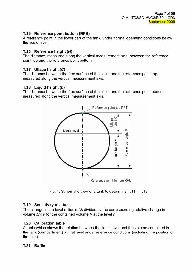
T.15 Reference point bottom (RPB) A reference point in the lower part of the tank, under normal operating conditions below the liquid level. T.16 Reference height (H) The distance, measured along the vertical measurement axis, between the reference point top and the reference point bottom. T.17 Ullage height (C) The distance between the free surface of the liquid and the reference point top, measured along the vertical measurement axis. T.18 Liquid height (h) The distance between the free surface of the liquid and the reference point bottom, measured along the vertical measurement axis.
Fig. 1: Schematic view of a tank to determine T.14 – T.18 T.19 Sensitivity of a tank The change in the level of liquid Δh divided by the corresponding relative change in volume ΔV/V for the contained volume V at the level h. T.20 Calibration table A table which shows the relation between the liquid level and the volume contained in the tank (compartment) at that level under reference conditions (including the position of the tank). T.21 Baffle
Page 8 of 56OIML TC8/SC1/WG3/R 80-1 CD3
September 2006
Internal device of the tank or compartment, e.g. a partition wall or obstacle inside the tank, intended to damp the movement of liquid during transport and to increase the mechanical stability of the tank. T.22 Level sensor Measuring device for the level of a liquid in a tank or compartment. T.23 Measuring range of the level sensor The range between the minimum and maximum possible indications of the level sensor. The lower limit is type and system dependent and shall be significantly less than the liquid level corresponding to the minimum measured quantity of the tank or compartment. The upper limit depends on the tank height and shall be above the maximum permissible filling height of the tank or compartment. T.24 Inclination sensor Measuring device for the pitch and roll angles. T.25 Longitudinal axis and pitch angle The symmetry axis of the tank parallel to the main direction of travel, when the tank is in normal position. The vertical angle by which this axis is rotated is referred to as pitch angle. It is positive if the front part of the tank is lifted. (schema will be added later) T.26 Transverse axis and roll angle The horizontal axis of tank perpendicular to the longitudinal axis, when the tank is in normal position. The vertical angle by which this axis is rotated is referred to as roll angle. It is positive if the right part of the tank (in relation to travel direction) is lifted. (illustration will be added later) T.27 Damping tube Mechanical device (usually in form of a tube with holes) intended to minimize or to eliminate the effect of surface waves on the level measurement and to protect the level sensor against mechanical damage. T.28 Transfer point Point at which the liquid is defined as being delivered or received. T.29 Empty hose (Dry hose) Hose and/or pipework containing liquid products only during a transaction and usually being completely evacuated before the transaction is terminated. It is connected downstream the transfer point ( the transfer point is located upstream of the delivery hose or downstream of the receiving hose). T. 30 Full hose (Wet hose) Hose and/or pipework filled with liquid product prior to and after a transaction. In this case the transfer point is located close to the outlet of the full hose (the transfer point consists of a closing device located in the delivery or receiving line).
Page 9 of 56OIML TC8/SC1/WG3/R 80-1 CD3
September 2006
T.31 Collector (Manifold) Collecting line connected via valves to the outlets of the measuring compartments and allowing delivery from any one or several compartments via common pipework. T.32 Direct discharger Tanker discharged by gravity, each individual measuring compartment having its own outlet. Frequently, the loading adapter is used as outlet. T.33 Top loading Loading of a measuring compartment from the top through the fill hole cover opened for this purpose. T.34 Bottom loading Loading of a measuring compartment from the bottom through a standardised dry adapter (e.g. API adapter) and the bottom valve that is integrated into the bottom of the measuring compartment and opened for this purpose. T.35 Transaction Delivery of liquid products from one or several measuring compartments to a recipient. Note: The transaction can also be a receipt (e.g. milk collecting truck). A transaction is settled
when the parties interested in the transaction have made their agreement known (explicitly or implicitly) as regards the amount of the transaction. This may be a payment, signing a credit card voucher, signing a delivery order, etc. The parties interested in a transaction may be the parties themselves or their representatives (for example: the employee in a filling station, the driver of a tanker).
T.36 Reference position Position for the discharge (or loading) of the measuring tank in accordance with the design drawing. It is the basis for the inclination correction function. The zero point of the inclination represents the zero point for both (longitudinal and transversal) inclinations. T.37 Working conditions The conditions to which the volume of liquid is to be measured, at the point of measurement (example: temperature, viscosity, position of the tank). T.38 Base conditions The specified conditions to which the measured volume of liquid is converted (example: temperature, density, pressure). T.39 Liquid detector Device intended to detect the presence of liquid in the pipework or the tank and to check, before start-up and after stop, that all or part of the measuring system is either filled completely with liquid (full hose measuring systems) or completely empty of liquid (empty hose measuring system). Note: A liquid detector may also be used for high level detection.
Page 10 of 56OIML TC8/SC1/WG3/R 80-1 CD3
September 2006
T.40 Liquid indicator A device to indicate the presence of liquid in the pipework (example: sight glass). T.41 Minimum measured quantity MMQ (Vmin) The smallest volume of liquid for which the measurement is metrologically acceptable for the tank or individually for each of its compartments. It shall be specified only for measuring systems suitable for measuring partial volumes. Alternatively, the terms “minimum delivery” or “ minimum receipt” may be used. T.42 Minimum specified volume deviation (Emin) Twice the absolute value of the maximum permissible error for the minimum measured quantity of a tank or compartment . T.43 Influence quantity Quantity which is not the object of the measurement but which influences the value of the measurand or the indication of the tank. T.44 Disturbance Influence quantity whose value lies within the limits defined by relevant requirements but outside the established rated operating conditions for the tank. T.45 Fault The difference between the error of indication and the intrinsic error of a measuring instrument. Notes: 1. Principally, a fault is the result of an undesired change of data contained in or flowing
through an electronic measuring instrument. 2. From the definition it follows that in this Document, a "fault" is a numerical value which
is expressed either in a unit of measurement or as a relative value, for instance in %.
T.46 Significant fault A fault greater than the value specified in 4.7.1. 4 T.47 Rated operating conditions Conditions of use giving the range of values of influence quantities for which specified metrological characteristics of a measuring instrument are intended to lie within given limits. T.48 Reference conditions Conditions of use prescribed for testing the performance of a measuring instrument or or intercomparison of results of measurements. f Note: The reference conditions generally include reference values or reference ranges for the
influence quantities affecting the measuring instrument. T.49 Influence factor An influence quantity having a value within the rated operating conditions of the measuring instrument specified in the relevant Recommendation.
Page 11 of 56OIML TC8/SC1/WG3/R 80-1 CD3
September 2006
T.50 Durability The ability of the measuring instrument to maintain its performance characteristics over a period of use. T.51 Intrinsic error The error (of the indicated volume) of a measuring system used under reference conditions. T.52 Initial intrinsic error The intrinsic error as determined prior to each performance tests. T.53 Symbols and abbreviations Vn nominal capacity (of the tank or compartment) Vt true volume Vi indicated volume H reference height C ullage height h liquid height Vmin minimum measured quantity Emin minimum specified volume deviation Ux expanded uncertainty of level measurement ΔVt,i partial volume at working temperature t t working temperature t0 base temperature ΔV0,i partial volume at base temperature V0 total volume at base temperature Vt total volume at working conditions φ(Vt,t) conversion function α0 thermal expansion coefficient ρ0 density at base conditions RPT reference point top RPB reference point bottom MMQ minimum measured quantity
Page 12 of 56OIML TC8/SC1/WG3/R 80-1 CD3
September 2006
1 Scope 1.1 This Recommendation specifies the metrological and technical requirements applicable to static measuring systems for volume of liquids other than water subject to legal metrology controls. It also provides requirements for the approval of parts of the measuring systems.
It applies to tankers for the transport of liquid products by road and rail and used, in addition to their functions as carriers, as transportable measuring tanks. Examples are given in Annexes 1 and 2. 1.2 Tankers may be considered as measuring instruments for liquids of which the viscosity does not exceed 20 mPa⋅s at working temperature. 1.3 This Recommendation is also applicable for measuring partial volume received or delivered. 1.4 Essential metrological requirements of this Recommendation are in accordance with the relevant requirements of OIML R 117 “Measuring systems for liquids other than water” [3] referring to measuring systems with liquid meters used for the same purpose. 1.5 In addition to the metrological and technical requirements included in this Part 1 (R 80-1) the methods of metrological controls and tests are given in Part 2 (R 80-2) and the test report formats in Part 3 (R 80-3). 1.6 This Recommendation does not include any aspects with respect to safety (see also 4.2.1).
Page 13 of 56OIML TC8/SC1/WG3/R 80-1 CD3
September 2006
2 Classification and Descriptions 2.1 General 2.1.1 Determination of the quantity in a road tanker or rail car involves: - the method of measurement to derive volume, - ancillary devices, - operating conditions (influence factors), - tank capacity and its calibration table, - the method of mounting of the tank. 2.1.2 Measurement methods: - level measured by a manual or visual (mechanical) level gauge, or electronic type
level gauge, - temperature measured by a electrical temperature sensor located on the
inlet/discharge line (pipe) - volume at working or base conditions delivered/received including partial deliveries
by an electronic computing device or controller, or by manual calculation using data from tank calibration table, and volume correction table.
The manual or visual gauging method may be based on - a single or more volumetric marks, - a graduated window in dome, - an other measuring device with a graduated scale (with a viewing window or an
external gauge tube or with any mean transferring the level position outside the tank),
- a dipstick or a dip tape. Electronic level gauging method may be based on - floats/displacers with electronic detection (magnetic or magneto-strictive), - ultrasonic level gauge, - radar (microwave) level gauge, - other non-contact level gauges such as electrical capacitance. Automatic volume measurements are by the electronic computing device or controller, and characterized by automatic volume determination. Note: This may include
- complete automatic control and supervision of the deliveries/receipts, - automatic taking into account of the influence of inclination, stage of emptying and/or
waves. 2.1.3 As regads the kind of delivery/receipt the tank may be designed for
- delivery/receipt of full compartment only - delivery/receipt of partial volume of a compartment - automatic measurement of the average temperatue of the delivered/received volume
Page 14 of 56OIML TC8/SC1/WG3/R 80-1 CD3
September 2006
- automatic volume conversion.
2.1.4 As regards ancillary devices, tanks may be with or without - installations for measuring partial volumes received or delivered, - internal pumps, - collectors, - full hose installations. 2.1.5 The main influence factors that can have a major effect during calibration and use of tankers are pressure and temperature.
a) As regards pressure, the tanks may be: - at atmospheric pressure, - under pressure (e.g. for liquefied gases or beer). b) As regards temperature, the tanks may be: - without means for heating and with or without thermal insulation of the contents, - with means for heating and with or without thermal insulation of the contents, 2.1.6 As regards the capacity of the tank, road tankers are usually between 0,5 m3 and 50 m3 and rail tankers between 10 m3 and 120 m3. 2.1.7 As regards the method of mounting, the tanks of road tankers may be: - mounted directly and permanently on the chassis of a vehicle, trailer, or semi-
articulated trailer, or be self-propelled, detachable, - mounted temporarily on the vehicle by means of devices that ensure that the
position of the tank when mounted on the vehicle remains unchanged. 2.2 Construction of tanks 2.2.1 If a tank is divided into compartments, each shall be considered as a separate tank and subject to the requirements of this Recommendation. 2.2.2 Tanks may be lined (e.g. for the transport of wine). 2.2.3 Each tank shall comprise a shell and ends and discharge devices. 2.2.4 The shape and the mounting of the tank as well as the installation of the discharge device shall be in such a way that the tank drains completely. 2.2.5 The discharge device shall comprise one or two discharge pipe(s) (allowing offloading on either side of the tanker), each equipped with a stop valve. The flow of liquid between the tank and the discharge pipe(s) may be stopped by a foot valve. If tank is equipped with two discharge pipes, suitable interlock facilities should prevent the use of both discharge pipes together.
Page 15 of 56OIML TC8/SC1/WG3/R 80-1 CD3
September 2006
If necessary, a tank may incorporate devices fitted at the lowest point for water separation. 2.2.6 Tanks with mechanical or electronic level gauges shall comprise: 2.2.6.1 A dome with reinforcing elements serving as a manhole and as an expansion space and in some (non-fuel) applications to increase the sensitivity of the tank. It is on the top of the tank.
The dome may incorporate the following: - a filling aperture, fitted with leak-proof cover, - an orifice for the observation of filling, - a venting device or double-acting safety valve.
The level index may be in the dome or in the upper part of the shell, provided that the sensitivity requirements are met. 2.2.6.2 For tanks with mechanical level gauges, a ladder shall be installed, giving access to the dome, and a platform for the operator performing the measurement or checking the tank. 2.2.6.3 For tanks with electronic level gauging - access to the interior of the tank shall either be prevented by sealing or other
means, - or visual checking of the interior shall easily be possible according to 2.2.6.2. 2.2.7 Tankers for liquefied gases shall not have domes and are subject to regulations covering the construction of pressure vessels. 2.2.8 Where appropriate, tanks shall be fitted with breather valves and flame arresters.
Page 16 of 56OIML TC8/SC1/WG3/R 80-1 CD3
September 2006
3 Units of measurement The authorized units of measurements are those of the International System of Units (SI). If units of measurement other than those of the SI are authorized by the state, these legal units of measurement may be used. Official conversion factors between these units of measurement and those of the SI shall be used for international commercial transactions.
Page 17 of 56OIML TC8/SC1/WG3/R 80-1 CD3
September 2006
4 Technical and metrological requirements 4.1 General
4.1.1. Rated operating conditions Measuring systems according to this Recommendation shall be designed and manufactured such that their errors do not exceed the maximum permissible errors iven in Table 1 under the following rated operating conditions: g
Rated operating conditions
low - 25 ° C (**) Environmental temperature high + 55 °C (**)
Humidity up to condensing Vibration less than 10 Hz – 150 Hz, 7 ms-2, 1 m2s-3,
-3dB/octave
Low voltage of internal battery (*) The lowest voltage at which the instrument functions properly according to the specifications 12 V battery 9 V – 16 V Voltage variations of a road vehicle
battery (*) 24 V battery 16 V – 32 V Inclination To be specified by manufacturer
(*) If applicable
(**) This value is to be decided by the national authority as it depends on the climatic conditions and the expected conditions of application (indoors, outdoors, etc.) that are different in different countries.
4.1.2 Accuracy classification and maximum permissible errors Depending on the field of application the static measuring systems mounted on the road or rail tankers are classified into four accuracy classes specified in Table 1.
Table 1: Accuracy classes and maximum permissible errors
4.1.3 Conditions for applying maximum permissible error 4.1.3.1 Maximum permissible errors in line A of Table 1 apply to complete measuring systems, under rated operating conditions, without any adjustment between the various tests, for: - type approval, - initial verification , - subsequent verifications. 4.1.3.2 Maximum permissible errors in line B of Table 1 apply to: - type approval of a measuring tank, under rated operating conditions, and - verification of the tank as a preliminary stage for initial verification of the measuring
system. 4.1.3.3 For measured volumes greater than the minimum measured quantity up to twice the minimum measured quantity, the absolute value of maximum permissible error need not to be less than Emin. 4.1.4 Base conditions Recommended base temperature is 15 °C. Other base temperatures such as 20 °C and 27 °C maybe used if established by the national metrology body in the country. Recommended base pressure is normal atmospheric pressure (0,1 Mpa). The use of other values for justified reasons is allowed. 4.1.5 Requirements on temperature measurement 4.1.5.1 For the purpose of volume conversion, the maximum permissible error for the determination of the temperature is ± 1 °C for accuracy class 2,5 and ± 0,5 °C for other accuracy classes. Note: These maximum permissible errors apply to the indication by the corresponding calculator with its indicating device and include the errors due to rounding if using digital inputs. 4.1.5.2 The temperature element (sensor) shall be installed in the inlet/discharge line beneath the tank at a location where under all discharge or loading modes the liquid stream passes by the sensor. In case of separate liquids paths, additional sensor shall be installed. 4.1.5.3 The measuring system shall allow to read out the actual temperature value. A permanent indication is not necessary. 4.1.6 Nominal capacity Nominal capacity of a measuring tank or of its compartment shall be at least 500 litres unless stated otherwise in the type approval certificate.
Page 19 of 56OIML TC8/SC1/WG3/R 80-1 CD3
September 2006
4.1.7 Minimum measured quantity 4.1.7.1 The minimum measured quantity shall be specified for each compartment of a tank and shall not exceed a quarter (1/4) of its nominal capacity. 4.1.7.2 The minimum measured quantity shall be equal or greater than the larger of the two following values: - volume corresponding to a level difference given in Table 2, in the range with the
smallest sensitivity; - volume calculated so that the change of it due to manufacturing tolerances of
volume (between the actual tank geometry and the design specifications) does not exceed three-fifth (3/5) of the maximum permissible error specified in line A of Table 1 for each permitted inclination.
Table 2: Minimum level difference corresponding to MMQ (Vmin)
Accuracy classes
0,5 1,0 1,5 2,5
level difference 200 mm 171 mm 190 mm 200 mm Note: The given level differences are based on an expanded uncertainty Ux for the
corresponding accuracy classes given in 4.4.3.1 Table 5. 4.1.7.3 The minimum measured quantity of a measuring system shall be given in one of the following forms: - 1 x 10n, 2 x 10n or 5 x 10n litres, where n is a whole number, - entire multiples of 100 litres. 4.2 Container of the measuring tank 4.2.1 Safety and other non-metrological requirements 4.2.1.1 National and international organisations, official services concerned with the transport of dangerous goods, and the authorities responsible for the supervision of the manufacture of pressure vessels lay down conditions for the construction of road and rail tankers intended for the transport of liquids contained in tanks, without overload and free from danger. Additional regulations for safety at work and protection against fire and explosion may exist. These conditions shall be observed. 4.2.1.2 In the case of tankers for potable liquids, the structural characteristics of the tank (shape, material, etc.) shall have no adverse effect on the quality of the liquid transported; the advice of the health authorities in this regard shall be sought. The application of the above-mentioned requirements shall be compatible with the measurement function of the tank.
Page 20 of 56OIML TC8/SC1/WG3/R 80-1 CD3
September 2006
4.2.1.3 The specification of the nominal capacity shall take into account the national or international regulations prescribing the maximum filling volume of tanks. 4.2.2 General requirements on construction of the container 4.2.2.1 Shapes, materials, reinforcing elements and methods of shaping or assembly shall be chosen so that the containers are sufficiently unaffected by atmospheric agents and the liquids they contain and are practically not subject to distortion under rated operating conditions. 4.2.2.2 The container must be tight. Proof by the safety tests carried out is generally sufficient. 4.3.2.3 The reference height H of a tank or each compartment shall not vary during
filling by more than the greater of the two values given in table 3.
Table 3: Maximum permissible variation of the reference height in dependence of the accuracy class
Accuracy classes
0,5 1,0 1,5 2,5
Maximum permissible variation of the reference height H (mm)
2 mm or H/1000 4 mm or H/500
4.2.2.4 The capacity of a compartment shall not change by more than one-third (1/3) of the maximum permissible error specified in line B of Table 1 when the neighbouring compartment or compartments are filled or emptied. 4.2.2.5 The material of the tank shall be chosen so that the capacity of the tank shall not change by more than three-fifth (1/3) of the maximum permissible error specified in line B of Table 1 when the temperature of the tank changes in the range of ± 10 °C from the reference temperature. Note: This condition is fulfilled if the linear expansion coefficient of the tankmaterial is less than
33·10-6 K-1 . 4.2.2.6 Tanks for liquids which are not measured at atmospheric pressure must be so designed that their capacity in the whole admissible pressure range does not change by more than one-fifth (1/5) of the maximum permissible error specified in line B of Table 1. 4.2.2.7 Every tank or compartment shall be of such a shape that no air is trapped on filling and liquid is not retained on emptying in any admissible position of use of the equipment.
Page 21 of 56OIML TC8/SC1/WG3/R 80-1 CD3
September 2006
4.2.2.8 Spouts, mouldings or vent pipes and valves may be used in order to comply with the above requirements. 4.3.2.3 The complete drainage must be ensured - by an adequate shape of the tank, - by a slope of at least 2 % (1,2 °) of the tank bottom with the vehicle on horizontal
ground or - by other means.
All road measuring tanks shall be designed to discharge within an inclination of at least ± 2% of the reference position. If complete drainage is not possible in all positions, which may be expected during use, monitoring/indicating facilities shall be provided to ensure complete emptying (for example, by additional liquid sensors in the compartment, or by monitoring the inclination). 4.2.2.10 Volume of liquid remaining in the tank or compartment after its complete draining shall not be greater than one-tenth (1/10) of the absolute value of the maximum permissible error given in line B of Table 1 applied to the capacity of the tank or compartment. This volume may remain in the tank for reasons of conditions of construction or mounting (for example, at the joints). 4.2.2.11 Baffles and reinforcing elements that may be fitted in the tank shall be of a shape and shall be provided with appropriate orifices so that filling, draining and checking the emptiness of the tank are not impeded. 4.2.2.12 The placing of dead wood inside the tank for the purpose of adjusting the capacity to a given value, or any other body which when removed or changed, could modify the capacity of the tanks, is prohibited. 4.2.2.13 Fixed internal elements in the measuring compartments (e.g. heating coils) are permitted if they have been present during the calibration and cannot be modified or dismounted. 4.2.2.14 The tank or compartment geometry should be such that waves at the liquid surface are adaquately damped. 4.2.2.15 To minimise inclination effects, the measuring tanks should be symmetrical both in the longitudinal and in the transverse direction and the level sensors should be installed centrally. Other constructions are permitted if correct volume measurement is ensured. 4.2.2.16 If correct measurement is not possible under all inclinations, which may be expected during use, the tank should be equipped with a device that indicates the actual inclination with respect to the range of inclinations required for a correct measurement.
Page 22 of 56OIML TC8/SC1/WG3/R 80-1 CD3
September 2006
4.2.2.17 The interior of the measuring tank must be accessible for inspection purposes via a manhole, provided safety or other regulations do not exclude it. 4.2.2.18 The capacity of a measuring tank must not deviate by more than 10 % from the capacity specified in the design documents. 4.2.2.19 The dome, when fitted, shall be on the upper part of the body and shall be welded to the latter. In general, the mechanical level-gauging device shall be inside the dome. 4.2.2.20 The dome may have a cylindrical or parallelepipedic form, with vertical side-walls. If the dome is parallelepipedic in form it may be of the same length as the tank itself. 4.2.2.21 If the sidewalls of the dome are mounted so that they penetrate the tank shell, and at the maximum permitted filling level air pockets could be formed, orifices or cut-outs of appropriate dimensions and at positions high enough to avoid such pockets shall be provided. 4.2.2.22 The transverse section of the shell and dome shall have a vertical axis of symmetry. Other constructions are permitted if correct volume measurement is ensured. 4.2.2.23 The dimensions of the horizontal section of the dome shall be such as to allow inspection of the interior of the tank. A diameter of at least 500 mm is recommended. 4.3 Additional devices 4.3.1 Discharge device
4.3.1.1 The discharge device shall ensure complete and rapid discharge of the liquid contained in the tank. For this purpose, the discharge device shall be connected to the lowest part of the tank shell. 4.3.1.2 For tanks of special construction for airports, the fitting of a device to collect water and impurities precipitated by a liquid contained in the tank is permitted. This device shall have a separate drain pipe, of small diameter, when the normal discharge pipe is not connected to the lowest part of the tank.
The collecting device may be mounted: - over the whole of the lower part of the tank, or - over a reduced area of the lower part. 4.3.1.3 The discharge pipe shall be as short as possible and have an adequate slope towards the stop valve. A resulting slope of at least 2° is recommended. 4.3.1.4 Each compartment shall have means for being discharged independently. A discharge manifold is permitted.
Page 23 of 56OIML TC8/SC1/WG3/R 80-1 CD3
September 2006
Manifolds without automatic control or monitoring shall have suitable control facilities that prevent the refuelling from one compartment to another. 4.3.1.5 The existence of a manifold shall be indicated in the certificate of calibration. 4.3.1.6 Stop valves shall be readily accessible and shall be at the rear or on the appropriate side of tank. 4.3.1.7 If a tank consists of more than one measuring compartment, each compartment must be provided with a separate (manual or automatic) shutoff device in each delivery line. Unwanted mixtures of the products from different compartments shall be prevented by constructive or control measures. 4.3.1.8 In the vicinity of the lowest point of each delivery line liquid detectors or sight glasses (except automatic measuring systems) shall be installed, if necessary for checking emptiness. 4.3.1.9 Pipework whose filling quantity has an effect on the measurement result must not be flexible and must have been rigidly laid. 4.3.1.10 For full hose delivery, it shall be ensured by a separate gas separator or an equivalent function of existing parts that the full hose is completely filled at the time of level gauging. 4.3.1.11 Control lines and control devices whose manipulation might falsify the measurement result shall be protected against tampering. 4.3.1.12 During a transaction, the change from full to empty hose and vice versa as well as the change between the full hose systems are admissible only if the filling levels are monitored in all measuring compartments so that manipulations are recognised. 4.3.1.13 Venting devices on the measuring system shall be protected against dismounting and removal as well as against manipulations from outside. 4.3.1.14 The measuring tank must have supports in the longitudinal and in the transverse direction at least 500 mm in length to accommodate an electronic water-level to mark the reference plane for the normal position of the measuring tank. 4.3.2 Installations for external measurement and pumping 4.3.2.1 If it is intended to connect the tank to separate pumping or measuring devices it should be provided with the appropriate detachable couplings which shall be as short as possible and easy to connect and disconnect. 4.3.2.2 Pumping installations shall comprise, in addition to the pump itself, no more than one filter and very short pipes (no valves nor branch connections). The installation shall be constructed so that it can be drained completely, each time the tank is emptied, without the need of any special measures.
Page 24 of 56OIML TC8/SC1/WG3/R 80-1 CD3
September 2006
4.3.2.3 For tanks equipped with an underneath manifold for measuring partial volumes delivered, the fitting of a diverting valve on each discharge pipe is permitted provided - that any leakage of liquid through the diverting valve can be detected
(for example: The underneath manifold ensures complete and rapid discharge of the liquid that it contains. A sight glass or monitoring device at its bottom end shall allow the checking of its emptiness), and
- that the installation and the control of the diverting valves is such that the product cannot flow back from one compartment to another.
4.3.2.4 Sampling device The measuring system may include a sampling device intended to determine the properties of the liquid to be measured.
Obtaining a representative sample is usually needed for the following reasons:
- to calculate the standard volume (i.e., volume at a defined base temperature); - to determine the density of the liquid for conversion; - to determine if the liquid transferred is within the quality specification, and its
properties.
It is not necessary to take into account the quantity of the sample in the results of the measurement if this sample is less than one-third (1/3) of the absolute value of the maximum permissible error given in line B of table 1 applied to the capacity of the tank or compartment. 4.3.2.5 Additivation systems The measuring system may include an injection device for additives to the delivered product. If the additivation ratio is not higher than 1:500 there is no need to measure the additive quantity. 4.3.3 Other devices 4.3.3.1 Tank may be fitted with: - level switch, - level detectors, - high level shutoff devices, - etc.
4.3.3.2 The use of devices to facilitate reading of the index, or to stop the flow automatically when the level of the liquid reaches the index, are permitted, provided that no additional measurement errors are introduced. 4.4 Level gauging system 4.4.1 General requirements
Page 25 of 56OIML TC8/SC1/WG3/R 80-1 CD3
September 2006
4.4.1.1 The level gauging device shall ensure a safe, easy and unambiguous readout, practically independent of tank tilt under rated operating conditions. 4.4.1.2 The index (e.g. volumetric marks, scales), or the vertical measurement axis, shall be as near as possible to the centre of horizontal sections of the tank. 4.4.1.3 The level gauging system shall perform a valid height measurement only when the liquid surface has calmed down so that the result is reproducible. 4.4.1.4 Whenever the measuring range of the level sensor has been exceeded, this must be recognised by means of an alarm message. 4.4.2 Requirements on level gauging for full compartment delivery 4.4.2.1 The shape of the tank shall be such that, in the zone where the level are gauged, a sensitivity equal or greater than values given in Table 4 is attained.
Table 4: Sensitivity of the tank in dependence of the accuracy class of the measuring system for full compartment delivery
Accuracy classes
0,5 1,0 1,5 2,5
Minimum sensitivity of tank Δh per ΔV/V in mm / ‰
(i. e. in mm for 1/1000 of measured volume)
1,5 1,0 0,5 0,3
4.4.2.2 It must be possible to gauge the level of the contained liquid manually. The gauging device should be positioned as close as possible to the curve connecting the centres of gravity of the horizontal cross sections of the compartment in the level measuring range.
When the lower end of the gauging device is close to the bottom of the tank, its axis should intersect the lower tank bottom at a point having no orifice or obstacle within a radius of 100 mm. If it is not the case there shall be an horizontal and non removable plate of 100 mm at least in all directions in order to ensure repeatability of measurements. 4.4.2.3 The reference points RPB and RPT shall be clearly defined and realised. 4.4.2.4 The joint between the shell and the dome shall be such that the gauging device can be held in a vertical position during measurement. 4.4.3 Requirements on level gauging for partial delivery
Page 26 of 56OIML TC8/SC1/WG3/R 80-1 CD3
September 2006
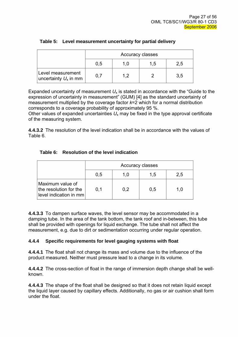
4.4.3.1 The expanded uncertainty of the level measurement shall not exceed values given in Table 5.
Page 27 of 56OIML TC8/SC1/WG3/R 80-1 CD3
September 2006
Table 5: Level measurement uncertainty for partial delivery
Accuracy classes
0,5 1,0 1,5 2,5
Level measurement uncertainty Ux in mm 0,7 1,2 2 3,5
Expanded uncertainty of measurement Ux is stated in accordance with the “Guide to the expression of uncertainty in measurement” (GUM) [4] as the standard uncertainty of measurement multiplied by the coverage factor k=2 which for a normal distribution corresponds to a coverage probability of approximately 95 %. Other values of expanded uncertainties Ux may be fixed in the type approval certificate of the measuring system. 4.4.3.2 The resolution of the level indication shall be in accordance with the values of Table 6.
Table 6: Resolution of the level indication
Accuracy classes
0,5 1,0 1,5 2,5
Maximum value of the resolution for the level indication in mm
0,1 0,2 0,5 1,0
4.4.3.3 To dampen surface waves, the level sensor may be accommodated in a damping tube. In the area of the tank bottom, the tank roof and in-between, this tube shall be provided with openings for liquid exchange. The tube shall not affect the measurement, e.g. due to dirt or sedimentation occurring under regular operation. 4.4.4 Specific requirements for level gauging systems with float 4.4.4.1 The float shall not change its mass and volume due to the influence of the product measured. Neither must pressure lead to a change in its volume. 4.4.4.2 The cross-section of float in the range of immersion depth change shall be well-known. 4.4.4.3 The shape of the float shall be designed so that it does not retain liquid except the liquid layer caused by capillary effects. Additionally, no gas or air cushion shall form under the float.
Page 28 of 56OIML TC8/SC1/WG3/R 80-1 CD3
September 2006
4.4.4.4 Within the permissible density range of the measured liquid at base conditions, the immersion depth of the float shall not change by more than the value given in Table 7. The permissible density range shall be specified in the type approval certificate. In measuring systems without corresponding correction the immersion depth change due to variation of liquid density, this influence should be included in the uncertainty evaluation of the level measurement.
Table 7: Change of float immersion depth
Accuracy classes Maximal change of immersion depth in mm for 0,5 1,0 1,5 2,5
- partial deliveries 0,5 0,8 1,6 2,5
- full compartment deliveries 1,5 2,4 4,8 7,5 4.4.5 Specific requirements for level gauging systems on the basis of ultrasound transit time measurements 4.4.5.1 Within the permissible product parameters range (mainly density and modulus of elasticity), the measured height shall not change by more than the values given in Table 5. The permissible ranges of product parameters shall be specified in the type approval certificate. 4.4.5.2 The effects of the product parameters on the transit time of the ultrasound signal may be compensated for by suitable methods, e.g. by reference marks. 4.5 Tank Calibration table 4.5.1 For the conversion of the result of the level gauging into volume, the electronic data processing system shall store a calibration table with pairs of level/volume values for each measuring compartment. Number and distance of these value pairs are selected according to the real tank geometry. Intermediate values are calculated by suitable interpolation. Extrapolation is not admissible. 4.5.2 The calibration table shall be determined for each compartment of the measuring tank by volumetric, gravimetric or geometric method. Note: A calculation of the calibration table only on the base of construction documents is not
permitted. 4.5.3 The level range of the calibration table shall encompass all filling states occurring in practical operation. Filling of a measuring compartment to a level beyond the maximum permissible point of the calibration table shall be prevented or to be recognised by means of an alarm message.
Page 29 of 56OIML TC8/SC1/WG3/R 80-1 CD3
September 2006
4.5.4 Volume effects of the inclination in the range specified for this system (pitch and roll angles) shall not exceed the minimum specified volume deviation for partial delivery or the value given in line B of table 1 of nominal compartment volume for full compartment delivery. 4.5.5 If compliance with the requirements of 4.1.5.2 and 4.1.5.3, respectively, requires that a correction for inclination should be made, the inclined position of the measuring tank shall be measured during level detection using inclination sensors rigidly fixed to the tank. The inclination data are used to correct the measurement using a suitable algorithm. 4.5.6 The calibration table compiled during the calibration as well as the inclination correction data, if any, shall be stored in the system so that they are protected from manipulation. 4.6 Metrological requirements for indicating and ancillary devices 4.6.1 Volume conversion 4.6.1.1 The maximum permissible error for the conversion of the measured volume into a volume at base conditions or a mass is equal to ± (A - B), A and B being the values specified in Table 1. However, the magnitude of the maximum permissible error shall not be less than the greater of the two following values: - one-half (1/2) scale interval of the indicating device for converted indications, - half of the value corresponding to the minimum specified volume deviation Emin.
4.6.1.2 The total volume at base conditions may be determined using either of the following two methods:
Method A: The conversion is performed during the measurement. Each partial volume ΔVt,i at working temperature t is converted to the partial volume ΔV0,i at base temperature t0
),Δ(Δ ,t,0 tVV ii ϕ=
The total volumeV0 at base conditions is then: ∑=
iiVV ,00 Δ
Method B: The conversion is done at the end of the measurement, using the
weighted average temperature, which is calculated from the working temperatures ti of the partial volumes ΔVt,i:
t
,tΔ
V
Vtt i
ii∑ ⋅=
Page 30 of 56OIML TC8/SC1/WG3/R 80-1 CD3
September 2006
The total volume V0 at base conditions is then
),( t0 tVV ϕ=
4.6.1.3 A conversion function φ(Vt,t) shall be used which is in accordance with the applicable International Recommendation or Standards (in particular, OIML R 63 [5]), or other methods accepted for national use. Annexes 3 and 4 (informative) show two examples of the use of such conversion functions. 4.6.1.4 During a transaction, the temperatures of liquid flowing through the particular delivery line shall be measured in proportion to the volume or the time. 4.6.1.5 If averaging proportional to the volume is used, the partial volumes must not be greater than one fifth of the minimum measured quantity:
5
Δ mint,
VV i ≤
4.6.1.6 If time proportional averaging is used, the time intervals must not be greater than the time needed to measure one fifth of the smallest measured quantity at maximum flow. 4.6.1.7 The total volume under measuring conditions is: ∑=
iiVV ,tt Δ
4.6.1.8 The maximum permissible error for determination of the weighted average temperature is ± 1 °C for accuracy class 2,5 and ± 0,5 °C for the other accuracy classes. 4.6.1.9 The data underlying the conversion (for instance the density ρo at base conditions or the thermal expansion coefficient αo) can be either firmly set or be adjustable in dependence on the product. They shall be protected from manipulations. 4.6.1.10 If the data according to 4.6.1.9 underlying the conversion can be adjusted in dependence on the product, the indication and, where appropriate, the printout must unambiguously reveal which values have been used or which liquid has been measured. 4.6.1.11 The measuring method - with temperature conversion of the volume or without conversion - for a given product shall be once selected at the time of verification. This selection may not be changed later. Similarly, for a given product, only one set of conversion data may be entered.
Page 31 of 56OIML TC8/SC1/WG3/R 80-1 CD3
September 2006
4.6.2 Indicating device 4.6.2.1 Reading of the indication shall be precise, easy and non-ambiguous. The customer shall be able to inspect it without particular measures. 4.6.2.2 The resolution of the indication shall be in the form 1, 2 or 5×10n where n is whole number and shall not exceed one tenth of Emin. 4.6.2.3 The continuous display of quantity during the period of measurement is only mandatory in the case of direct sale to the public. 4.6.2.4 The output of all measured and calculated values shall be possible. Additionally, when the volume of a product at base conditions is indicated, it shall be possible to access all values underlying the conversion. However, it is not necessary to permanently indicate all values. 4.6.2.5 The kind of the indicated quantity (metering or base condition) must be unequivocal. 4.6.2.6 The measuring system may have several units for indicating the same measuring quantity. Each of these indications shall satisfy all requirements specified. 4.6.2.7 Other information, which does not serve metrological purposes, may be additionally indicated but they must not give rise to false interpretation. 4.6.2.8 In the case of correction of a quantity, the non-corrected quantity shall not be displayed in normal operation. The non-corrected quantity shall, however, be available for test purposes. 4.6.3 Price calculation Optionally, before or after the delivery, a unit price for a delivered product may be entered. The unit price is used to calculate the total price, which may be printed on the delivery note or invoice. 4.6.4 Printing device 4.6.4.1 Printing devices are mandatory only for measuring systems for direct sales to the public. In this case, the system must check before the delivery or receipt starts whether a printer is connected for this transaction, possibly also temporarily. 4.6.4.2 Data to be printed If a delivery/receipt document is generated, it shall contain at least the following data: - an identifier for the measuring system (e.g. serial number, number plate of the semi-
trailer, or number of compartment), - the product name or product group name, - a unique number, which shall be incremented for each transaction, - the volume Vt at working conditions with the remark “at delivery/receipt
temperature” and/or the volume V0 at base conditions.
Page 32 of 56OIML TC8/SC1/WG3/R 80-1 CD3
September 2006
4.6.4.3 Printing of multiple results If during a transaction more than one compartment is used for delivery/receipt, all the results may be printed on the same delivery/receipt document. If more than one result is available for the same product, these results may be summed up. 4.6.4.4 Marking of data Verified data shall be enclosed by special characters (e.g. an asterisk “ ”). It is not allowed to enclose non-verified data by asterisks.
The delivery document shall contain the following explanatory note: “Data from verified devices are enclosed in asterisks ”
The remark may either be printed at the time the document is generated, or pre-printed on the paper or the rear of the paper being used for the printout. 4.6.5 Memory device 4.6.5.1 Measuring systems may be fitted with a memory device to store measurement results until their use or to keep a record of commercial transactions, providing proof in case of a dispute. Devices used to read stored information are considered as included in the memory devices. 4.6.5.2 In the case of measuring systems not used for direct sales to the public, the printing device may be replaced by a data memory. In this case, all data necessary for the printout shall be stored. 4.6.5.3 The medium on which data are stored must have sufficient permanency to ensure that the data are not corrupted under normal storage conditions. 4.6.5.4 There shall be sufficient memory storage for any particular application for which the measuring system is used. 4.6.5.5 Unless otherwise specified, the measured data shall be stored for at least the billing period and the period for objection before being erased. If the capacity of the data memory is exhausted and if stored data cannot be erased because mentioned periods have not yet elapsed, it shall not be possible to start a new measurement. 4.6.5.6 If the measured data have been printed or transferred out at least once in a way acceptable for verification, they may be erased. 4.6.6 Automatic stop If the system is able to stop the delivery or the loading, it is admissible to automatically terminate the delivery or the loading after a given difference or final quantity has been reached. It is not necessary to reach the given quantity exactly. Note: This option is not a volume pre-setting as described in OIML R117 and therefore must
not be used for prepaid transactions.
Page 33 of 56OIML TC8/SC1/WG3/R 80-1 CD3
September 2006
Page 34 of 56OIML TC8/SC1/WG3/R 80-1 CD3
September 2006
4.7 Additional requirements for measuring systems with electronic parts 4.7.1 General requirements 4.7.1.1 The electronic parts of the measuring system shall be designed and fabricated such that the maximum permissible errors specified in 4.1.2 are not exceeded under rated operating conditions specified in 4.1.1. 4.7.1.2 Disturbances Measuring instruments according to this Recommendation shall be designed and manufactured such that when they are exposed to the following disturbances, either:
(a) Significant faults do not occur, or (b) Significant faults are detected and acted upon by means of a checking facility: 4.7.1.2.1 during the following disturbances
Radiated, radio-frequency, electromagnetic fields Conducted radio-frequency fields Electrostatic discharge Power frequency magnetic field Bursts (transients) on signal, data and control lines Surges on signal, data and control lines Transients due to sudden interruption of current in a device connected in parallel to the measuring instrument. (pulse 2a) Transients as a result of the switching process (pulses 3a and 3b) In case the measuring instrument and the starter motor of the vehicle are energized by the same battery: Supply voltage reduction caused by the energizing the starter motor (pulse 4) Electrical transient conduction via lines other than supply lines for external 12 V and 24 V batteries
4.7.1.2.2 after the following disturbances
Damp heat, cyclic (condensing) In case the measuring instrument is connected to the battery via the main ignition switch of the car: Transients from DC motors acting as generators after the ignition is switched off (pulse 2b)
Note: A fault equal to or smaller than the significant fault is allowed irrespective of the value of
the error of indication. 4.7.1.2.3 Application The provisions in 4.7.1.2 (a) and 4.7.1.2 (b) may be applied separately to:
(a) Each individual cause of significant fault; and/or (b) Each part of the measuring instrument.
Page 35 of 56OIML TC8/SC1/WG3/R 80-1 CD3
September 2006
The choice of whether 4.7.1.2 (a) or 4.7.1.2 (b) is applied, is left to the manufacturer, unless the relevant Recommendation specifies otherwise in view of the intended use of the measuring instrument or the nature of measurement. 4.7.1.2.4 Durability The provisions in 4.1.3 and 4.7.1.2 shall be met durably.
Measuring instruments according to this Recommendation shall be designed and manufactured such that either:
(a) Significant durability errors do not occur, or (b) Significant durability errors are detected and acted upon by means of a durability
protection facility.
The provisions in (a) and (b) may be applied separately to each part of the measuring instrument (for example: analogue and digital parts).
The choice of whether (a) or (b) is applied is left to the manufacturer, unless the relevant Recommendation specifies otherwise. 4.7.1.3 Presumption of compliance The type of a measuring instrument according to this Recommendation is presumed to comply with the provisions in 4.1.3 and 4.7.1.2 if it passes the examination and tests specified in Part 2 of this Recommendation. 4.7.1.4 The significant fault is the greater of the following two values for the measured volume of liquid: - 1/5 of the maximum permissible error of the relevant measured quantity or - the minimum specified volume deviation Emin defined according to T. 42.
4.7.1.5 The following faults are not significant faults, even when they exceed the value defined in 4.7.1.4:
(a) faults arising from simultaneous and mutually independent causes (e.g. electromagnetic fields and discharges) originating in the measuring instrument or in its checking facilities,
( b) faults implying the impossibility to perform any measurement,
(c) transitory faults being momentary variations in the indication, which cannot be interpreted, memorized or transmitted as a measurement result,
(d) faults giving rise to variations in the measurement result that are serious enough to
be noticed by all those interested in the measurement result; the relevant Recommendation may specify the nature of these variations.
4.7.2 Power supply 4.7.2.1 If the transaction is not interrupted in case the power supply fails, the measuring system shall be provided with an emergency power supply device to safeguard all measuring and control functions during the failure.
Page 36 of 56OIML TC8/SC1/WG3/R 80-1 CD3
September 2006
4.7.2.2 If the transaction is interrupted in case the power supply fails, the requirements of 4.7.2.1 shall be met, or the data contained at the moment of the failure shall be saved and displayable for a sufficiently long time on an indicating device subject to legal control so that the current transaction can be completed. The absolute value of the maximum permissible error for the indicated volume in this case is increased to 5 % of the minimum measured quantity. 4.7.2.3 In the case 4.7.2.2, it is also sufficient to indicate the result of the measurement after re-establishing the power supply. 4.7.2.4 Alternatively, in the case of 4.7.2.2, the transaction may be terminated properly after re-establishing of the power supply, in which case the maximum permissible errors according to 4.1 apply. 4.7.3 Checking facilities 4.7.3.1 The checking facilities serve to detect a disturbance whose effects on the measured volume exceed the significant fault according to 4.7.1.3 and shall have the following effect: - automatic correction of the change in volume, or - stopping only the faulty device when the measuring system continues to comply
with the regulations without this device being in operation, or - stopping the transaction.
4.7.3.2 For measuring systems with level gauging systems only checking facilities of type I or P are permitted. Type I is an intermittent automatic checking facility acting at least once at the beginning and at the end of each transaction, and type P is a permanent automatic checking facility operating during the whole duration of the transaction. 4.7.3.3 Checking facilities for the level sensors (type P), the temperature sensors (type P), the liquid indicators (type I) as well as for the inclination sensors (type I) shall be provided to ensure the availability of the sensor, its perfect operation, the correctness of data transmission as well as, where appropriate, compliance with the specified measurement range. 4.7.3.4 During type approval and initial verification it shall be possible to check that the checking facilities function correctly, e.g. - by disconnecting the sensor or - by interrupting the signalling circuit or - by interrupting the power supply.
4.7.3.5 The checking facility for the functioning of the computer checks the values of all permanently stored instructions and data as well as all procedures for the internal transmission and storage of the data relevant to the measurement result and shall be of type I or P.
Page 37 of 56OIML TC8/SC1/WG3/R 80-1 CD3
September 2006
4.7.3.6 The checking facility for the correctness of the calculations carried out by the computer must be of type P. This check can be carried out, for example, with the aid of a parity bit, a checksum or double storage. 4.7.3.7 The checking facility for the indicating device will ensure that a failure or maloperation of individual elements is detected visually and/or automatically or cannot lead to erroneous interpretation. The automatic detection can, for example, take place by monitoring the current between the segments of LED displays or by measurement of the grid voltage of fluorescent displays. The visual check can, for example, be carried out by redundant LC segments (graphics LCD) or a black-and-white test. 4.7.3.8 It must be possible during initial verification to check the checking facility for the indicating device, for example, by disconnecting the whole or part of the indicating device (in the case of an automatic checking facility) or by a visual check of a manually or automatically triggered black-and-white test. 4.7.3.9 Checking facilities for ancillary devices (e.g. according to 4.6.2 to 4.6.5) must ensure that the particular ancillary device is available, if necessary, and that the transmission of the data is valid. 4.7.3.10 The checking facility for a printing device must also monitor the presence of paper.
Page 38 of 56OIML TC8/SC1/WG3/R 80-1 CD3
September 2006
5 Plates, documents and sealing 5.1 Identification plate 5.1.1 Each tank shall be provided with an identification plate, which is clearly visible and easily legible. The plate shall not be of a material that deteriorates under the rated operating conditions of the tank and should allow the data to be easily inscribed. The plates shall be fixed in such a way that they cannot be removed without breaking the seals bearing with marks of the Legal Metrology Service. 5.1.2 The following information shall be inscribed on the plate:
- name or trademark of the manufacturer, - type and year of manufacture (year may be given as a part of serial number), - serial number of the tank, - serial number of the level gauging system, if appropriate, - type approval number, if appropriate, - nominal capacity of the tank or of each compartment, - accuracy class if other than 0.5, - the minimum measured quantity of the tank or of each compartment, - base temperature, - range of specified inclination, if it differs from 2%. 5.1.3 A free area shall be left on the plate for the periodic verification marks, according to national regulations. 5.2 Measuring system document 5.2.1 Upon initial verification of a measuring system a measuring system document shall be drawn up. This document shall contain at least:
- all statements given on the identification plate, - sealing plan, - pipework diagram, - pneumatics diagram with the metrologically significant control lines marked, - calibration parameter printout and calibration tables, if applicable, - maximum rated diameter and maximum length of the full hoses, if available, - extra sheets with descriptions of changes to the measuring system, repairs as well
as any breaking of official seals including their confirmations, - signatures for the software relevant to verification and its parameters, if applicable. 5.2.2 The measuring system document is part of the measuring system and shall be kept on the tanker. 5.3 Calibration plate on tanks with dipsticks scaled in non-volumetric units
Page 39 of 56OIML TC8/SC1/WG3/R 80-1 CD3
September 2006
In this case the measuring system documents may be replaced by a calibration plate for the tank or for each compartment which shall be fixed on the tank with the following information:
- institution which calibrated the tank and prepared the calibration table, - calibration certificate number, - base temperature, - number of heating coils, if appropriate, - calibration table (as a function of V(h) or V(C)).
5.4 Calibration certificate 5.4.1 In conformity with national regulations a calibration certificate may be required. 5.4.2 In the case of road tankers, the calibration certificate shall include the following information:
- issuing authority and certificate number - name and, if appropriate, address of holder - manufacturer’s name or trademark, type, year of manufacture and serial number - vehicle registration number, if appropriate - number of compartments and heating coils, if appropriate - identification of the reference point and the vertical measurement axis, if appropriate - method of calibration used, number of calibration certificate for the standard
installation used - convention relating to the filling of the discharge pipes, if appropriate, indication of
the presence of a manifold - uncertainty of the determination of the values of volume indicated in the certificate - date of issue and limit of validity of the calibration certificate, if a limit is set
Note: A period of validity of 2 to 5 years is recommended. - title, name and signature of the person responsible for the calibration - sketch indicating the meaning of the symbols used - height of coupling during verification (for semi trailers only) - number and positions of the applied verification marks.
For each compartment, the calibration certificate shall indicate: - the nominal capacity - the total capacity - the ullage height corresponding to the nominal capacity, in millimetres - reference height, in millimetres - the sensitivity of the tank at the level of the nominal capacity or calibration table, in
legal units of measurement. 5.4.3 In the case of rail tankers, the calibration certificate shall include the following information:
- issuing authority and certificate number - registration number of rail tanker - name and, if appropriate, address of owner and manufacturer
Page 40 of 56OIML TC8/SC1/WG3/R 80-1 CD3
September 2006
- method of calibration, if appropriate, and place and date of the tests - identification of the reference point and the vertical measurement axis - conventions concerning filling of the tank and discharging pipework - reference height, in millimetres - total contents and corresponding ullage height - capacity of tank body, up to the upper internal generator, and corresponding ullage
height - reference temperature (on which the table is based) - uncertainty of the determination of the values indicated in the certificate - limit of validity of the certificate as regards the use of the tank as a measuring
instrument Note: A period of validity of 4 to 5 years is recommended.
- date of issue of the calibration certificate - title, name and signature of the person responsible for the calibration - sketch indicating the meaning of the symbols used - calibration table giving, in legal units, the volume of the liquid contained in the tank
against the ullage height or the liquid height expressed in millimetres, within the range of level gauging
- number and positions of the applied verification marks.
5.5 Seals 5.5.1 All measuring systems shall be sealed in such a way that manipulations can be prevented and/or detected. The following locations for seals are recommended:
- indicating devices of the level gauging system, - controller and interface units, - terminal boxes with cables relevant to the measurements (e.g. for temperature and
liquid detector), - inclination sensors, - temperature sensors, - liquid detectors, except they need removal for cleaning, - dipsticks on upper and lower fastening, where relevant - identification plate of measuring system, operating instructions and pneumatic and
pipework diagram, if applicable - dome cover and man holes of tank compartments in measuring systems which can
be filled from the bottom only, - heating coils, if provided, shall be sealed at their points of junction with the tank
body. 5.5.2 Seals are not applied to the pipework system. 5.5.3 The locations for seals must be so arranged that sealing and external administrative examination are possible without hindrance. They are fixed individually for each type of measuring system within the type approval certificate.
Page 41 of 56OIML TC8/SC1/WG3/R 80-1 CD3
September 2006
6 Bibliography [1] International Vocabulary of Basic and General Terms in Metrology (VIM). BIPM,
IEC, IFCC, ISO, IUPAC, IUPAP and OIML. International Organization for Standardization, Geneva, 1993
[2] International vocabulary of terms in legal metrology (VIML). OIML, Paris, 2000 [3] OIML International Recommendation R 117. Measuring systems for liquids other
than water. OIML, Paris, 1995 (Being revised, 2004) [4] Guide to the expression of uncertainty in measurement. BIPM, IEC, IFCC, ISO,
IUPAC, IUPAP and OIML. International Organization for Standardization, Geneva,1995
[5] OIML International Recommendation R 63. Petroleum measurement tables (with
reference to the ISO International Standard 91-1:1982 & 91-2:1991). OIML, Paris, 1994
[6] OIML International Document D 11. General Requirements for electronic measuring
instruments. OIML, Paris, 2004
Page 42 of 56OIML TC8/SC1/WG3/R 80-1 CD3
September 2006
ANNEX 1
EXAMPLES FOR TANKERS WITH MECHANICAL SENSORS (Informative)
Page 43 of 56OIML TC8/SC1/WG3/R 80-1 CD3
September 2006
Page 44 of 56OIML TC8/SC1/WG3/R 80-1 CD3
September 2006
Fig. A.1-1: Single or two (opposite) volumetric marks or indexes in the dome
Fig. A.1-2: Top edge of the index fixed on holder (one-mark dipstick)
Page 45 of 56OIML TC8/SC1/WG3/R 80-1 CD3
September 2006
Fig. A.1-3: Single mark or graduated window in dome
Section A-A
Page 46 of 56OIML TC8/SC1/WG3/R 80-1 CD3
September 2006
Fig. A.1-4: Single volumetric mark in tank (on console fixed to dome)
Fig. A.1-5: Mechanical dipstick with sliding index
Page 47 of 56OIML TC8/SC1/WG3/R 80-1 CD3
September 2006
Fig. A.1-6: Examples of mechanical dipsticks and placement of RPT
Page 48 of 56OIML TC8/SC1/WG3/R 80-1 CD3
September 2006
Fig.A.1-6: Examples of mechanical dipsticks and placement of RPT Note: This figure indicates the level gauging of light oil, such as gasoline, kerosene, diesel oil, and so on, and many chemical products. These products and other liquid products with low density and low viscosity are usually gauged by liquid height, but not ullage height. This figure should be included in Fig.A.1-6.
1 5
Vt
Vn
h H
RPManhole
Page 49 of 56OIML TC8/SC1/WG3/R 80-1 CD3
September 2006
ANNEX 2
EXAMPLES FOR AUTOMATIC MEASURING SYSTEMS WITH ELECTRONIC LEVEL GAUGING
(Informative)
Fig. A.2-1: Schematic set-up of the measuring system of a tanker for oils in its
maximum version (for explaining the basic components and functions) (1) level sensor (2) measuring tank/measuring compartment (3) float, if appropriate (4) product (5) bottom valve (6) discharge line (7) dry coupler (API) (8) liquid detector (if appropriate, in collector line and downstream of pump) (9) collector vent valve (10) collector line (shown with valve function) (11) filter system (12) pump (13) level sensor for pipe system, alternatively: gas separator (14) draining, if appropriate (15) valve of empty hose (16) coupler of empty hose with filter and inspection glass (alternative positions) (17) hose reel with full hose
Page 50 of 56OIML TC8/SC1/WG3/R 80-1 CD3
September 2006
(18) valve of full hose 2 (19) valve of full hose 2 (reduced delivery without shutdown valve) (20) valve of full hose 1 (21) non-return valve (22) temperature sensor (23) ventilation, if appropriate (24) electronic measuring and control unit (25) control apparatus for pump motor, if necessary (26) delivery line to the right, if appropriate
Page 51 of 56OIML TC8/SC1/WG3/R 80-1 CD3
September 2006
Fig. A.2-2: Schematic set-up of the measuring system of a road tanker for milk in its maximum version (for explaining the basic components and functions)
(1) level sensor (2) measuring tank/measuring compartment (3) float, if appropriate (4) valve for compartment 1 (5) pipe empty sensor (6) valve for pumping to the trailer (7) valve for compartment 2…n (8) valve for pumping to the trailer (9) valve for pumping to the trailer (10) non-return valve (11) transfer point sensor (12) transfer point with inspection glass (13) pump with control apparatus for pump motor, if necessary (14) suck bottle (15) pressure air valve (16) suck bottle level sensor (17) vacuum valve (18) suck bottle clearing valve (19) milk sampling system (20) pressure air valve (21) mainstream suck valve (22) temperature sensor (23) vacuum sensor
Page 52 of 56OIML TC8/SC1/WG3/R 80-1 CD3
September 2006
(24) suction hose (25) suction lance (26) electronic measuring and control unit
Page 53 of 56OIML TC8/SC1/WG3/R 80-1 CD3
September 2006
ANNEX 3
EXAMPLES FOR VOLUME CONVERSION FROM OBSERVED TEMPERATURE TO 15 °C (FROM WORKING TO BASE CONDITIONS)
– PETROLEUM PRODUCTS AND LUBRICANTS (Informative)
The volume conversion of mineral oils is based on the following rules:
Product group Tables Conversion Equation
Generalized Petroleum Products
Correction of volume to 15°C against density at
15°C
B
Manual of Petroleum Measurement Standards
Chapter 11.1.54.4 – Volume Correction Factors
ASTM D 1250-80 Volume VIII, Table 54B
Chapter 11.1.54.4 – 6
ASTM D 1250-80 Volume X
Generalized Lubricating Oils
Correction of volume to 15°C against density at
15°C
D
Manual of Petroleum Measurement Standards
Chapter 11.1.54.10 – Volume Correction Factors
ASTM D 1250-82 Volume XIV, Table 54D
Chapter 11.1.54.10
ASTM D 1250-82 Volume XIV
The conversion (volume correction factor) is based on the following constants:
Product group Oil group Range of
density [kg/m³]K0
[(kg/m³)²/°C]
K1
[(kg/m³)/°C] function
Petrol
Naphtha
600,0 – 770,4
770,5 – 787,5
346,4228
-0,00336312
0,4388
2680,3206
2.2
2.3
Jet-A-1 Kerosene 787,6 – 838,5 594,5418 0,0 2.2
Generalized Petroleum Products
B
Fuel oil 838,6 – 1200,0 186,9696 0,4862 2.2
Generalized Lubricating
Oils D Lubricants 750,0 – 1164,0 0,0 0,6278 2.2
The volume correction factor (VCF) for product group B and D:
[ ])8,01( 151515
ttEXPVCF tt Δ××+×Δ×−== αα
ρρ
where
15
1215
15 ρρα
KKo +=
or
Page 54 of 56OIML TC8/SC1/WG3/R 80-1 CD3
September 2006
215
115 ρ
αKKo +=
Page 55 of 56OIML TC8/SC1/WG3/R 80-1 CD3
September 2006
ANNEX 4
EXAMPLES FOR VOLUME CONVERSION FROM OBSERVED TEMPERATURE TO 15 °C (FROM WORKING TO BASE CONDITIONS)
– LIQUIFIED PETROLEUM GAS (LPG) (Informative)
The volume conversion of liquefied petroleum gas is based on the following rules:
Product group Tables Conversion Function
Generalized light products (LPG)
Correction of volume to 15°C against density at
15°C
X Density determination
(54 X)
DIN 51 757 Annex B and Annex G
The constants P1, P2 and P3 used to calculate the volume correction factor (VCF) are: Range of density
Tanaka, M.; Girard, G.; Davis, R.; Peuto, A.; Bignel, N.: Recommended table for the density of water between 0 °C and 40 °C based on recent experimental reports. Metrologia, 2001, 38, 301-309