28.04.2009 1 ETH Zürich Institute for Geodesy and Photogrammetry - Prof. Dr. H. Ingensand Road Design Road Design Werner Stempfhuber Werner Stempfhuber 30.4.2009 (Lecture and Exercise) 30.4.2009 (Lecture and Exercise) ETH Zürich Institute for Geodesy and Photogrammetry - Prof. Dr. H. Ingensand - Introduction - Reference Network - Transformation Parameter – Coordinate Systems - Design Parameter & Definition - Design Preparation (Leica System1200 OnBoard ATK, Liscad) - Calculation - Stake Out with the Leica RoadRunner - As Built Check - Exercise Content Content
Transcript
28.04.2009
1
ETH ZürichInstitute for Geodesy and Photogrammetry - Prof. Dr. H. Ingensand
Road DesignRoad Design
Werner StempfhuberWerner Stempfhuber
30.4.2009 (Lecture and Exercise)30.4.2009 (Lecture and Exercise)
ETH ZürichInstitute for Geodesy and Photogrammetry - Prof. Dr. H. Ingensand
ETH ZürichInstitute for Geodesy and Photogrammetry - Prof. Dr. H. Ingensand
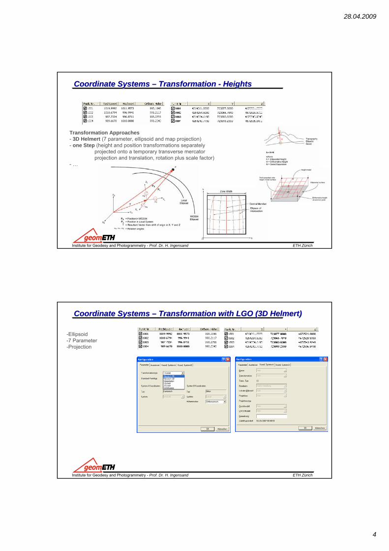
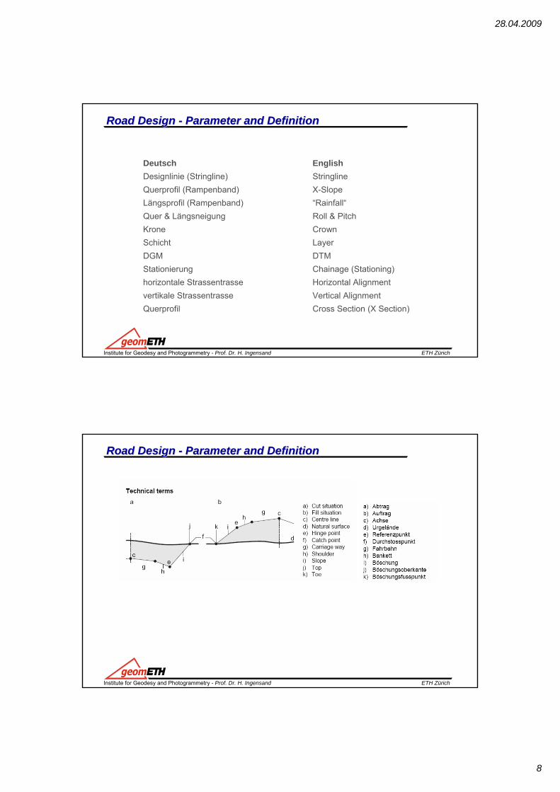
Road Design Road Design -- Parameter and DefinitionParameter and Definition
28.04.2009
9
ETH ZürichInstitute for Geodesy and Photogrammetry - Prof. Dr. H. Ingensand
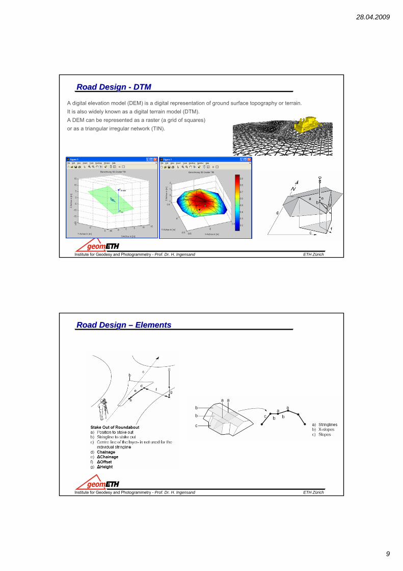
Road Design Road Design -- DTMDTM
A digital elevation model (DEM) is a digital representation of ground surface topography or terrain. It is also widely known as a digital terrain model (DTM). A DEM can be represented as a raster (a grid of squares) or as a triangular irregular network (TIN).
ETH ZürichInstitute for Geodesy and Photogrammetry - Prof. Dr. H. Ingensand
Road Design Road Design –– ElementsElements
28.04.2009
10
ETH ZürichInstitute for Geodesy and Photogrammetry - Prof. Dr. H. Ingensand
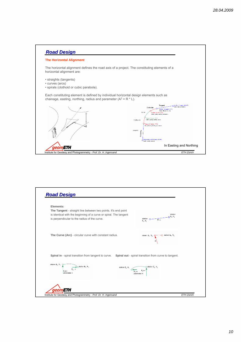
Road DesignRoad DesignThe Horizontal Alignment
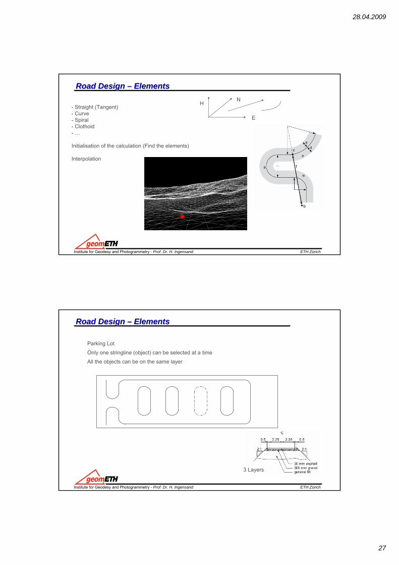
The horizontal alignment defines the road axis of a project. The constituting elements of ahorizontal alignment are:
• straights (tangents)• curves (arcs)• spirals (clothoid or cubic parabola).
Each constituting element is defined by individual horizontal design elements such aschainage, easting, northing, radius and parameter (A2 = R * L).
In Easting and Northing
ETH ZürichInstitute for Geodesy and Photogrammetry - Prof. Dr. H. Ingensand
Road DesignRoad Design
Elements:The Tangent - straight line between two points. It's end pointis identical with the beginning of a curve or spiral. The tangentis perpendicular to the radius of the curve.
The Curve (Arc) - circular curve with constant radius.
Spiral in - spiral transition from tangent to curve. Spiral out - spiral transition from curve to tangent.
28.04.2009
11
ETH ZürichInstitute for Geodesy and Photogrammetry - Prof. Dr. H. Ingensand
Road DesignRoad DesignThe Vertical AlignmentThe vertical alignment gives information about the pattern of heights of the road axis as itis defined in the horizontal alignment.The constituting elements of a vertical alignment are:
Each constituting element is defined by individual vertical design elements such aseasting, northing, radius and chainage.
Height
Chainage
0+00
0.00
ETH ZürichInstitute for Geodesy and Photogrammetry - Prof. Dr. H. Ingensand
Road DesignRoad Design
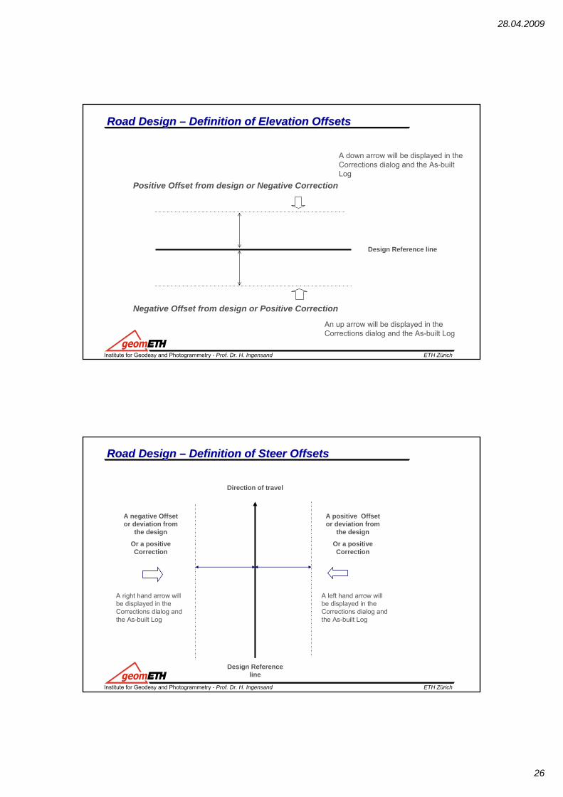
Cross SectionA cross section gives a profile view. It requires vertical alignment or actual elevation on each station.The constituting elements are straight elements. The points are called vertices. You may optionally define slopes at the vertices most left and most right.
Points are defined by:• ∆H and ∆V• ∆H and slope in percentage• ∆H and slope ratio∆H horizontal distance from the centre line∆V vertical distance from the centre line (vertical alignment or actual elevation mandatory) − ∆V
28.04.2009
12
ETH ZürichInstitute for Geodesy and Photogrammetry - Prof. Dr. H. Ingensand
Road DesignRoad Design -- Station EquationStation Equation
Re-calculation
ETH ZürichInstitute for Geodesy and Photogrammetry - Prof. Dr. H. Ingensand
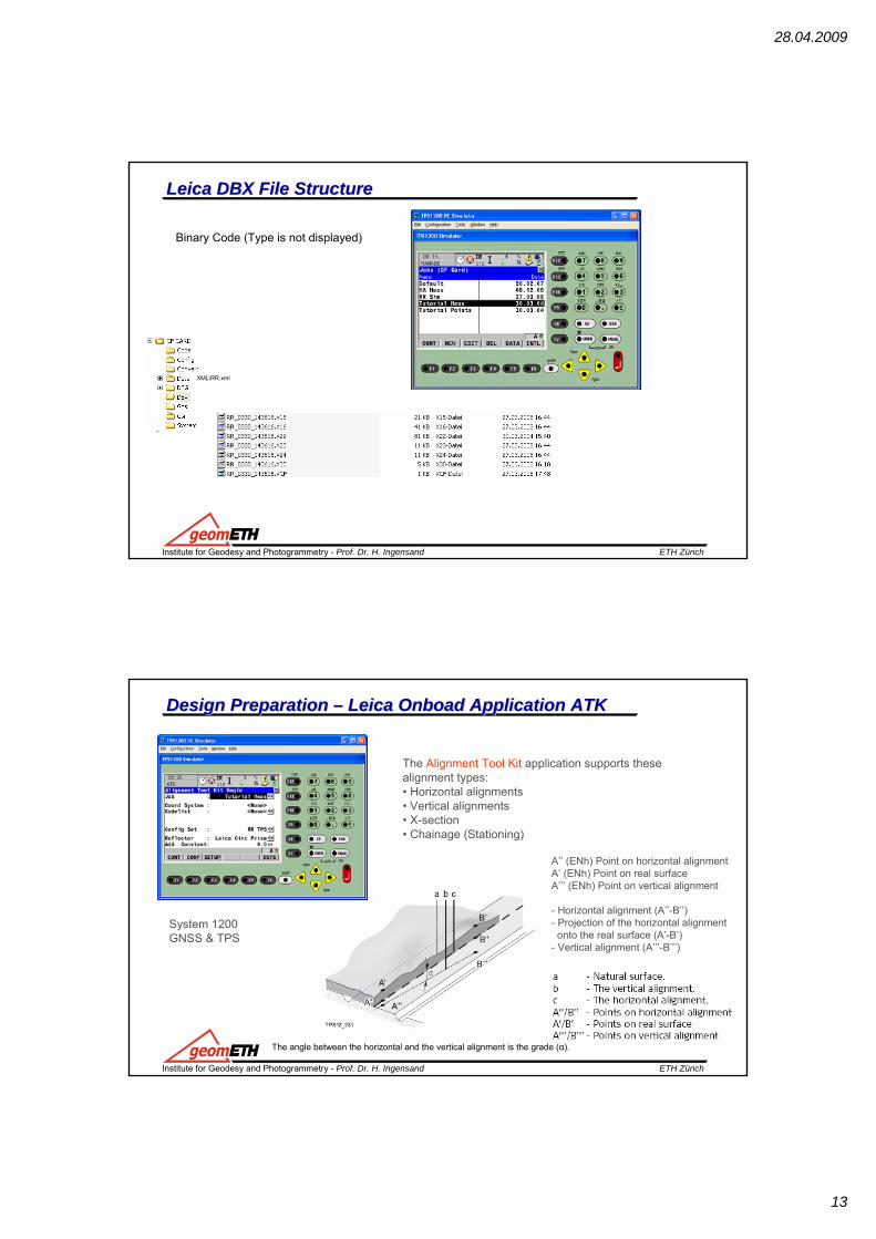
Leica uses the concepts of Projects and Jobs.A Project is a collection of designs, alignment references and localization sets specific to a job. A Project can support multiple JobsJobs are groupings of data to fulfill a specific application.Each Job is collection of Reference Lines
28.04.2009
13
ETH ZürichInstitute for Geodesy and Photogrammetry - Prof. Dr. H. Ingensand
Leica DBX File StructureLeica DBX File Structure
Binary Code (Type is not displayed)
XML\RR.xml
ETH ZürichInstitute for Geodesy and Photogrammetry - Prof. Dr. H. Ingensand
ETH ZürichInstitute for Geodesy and Photogrammetry - Prof. Dr. H. Ingensand
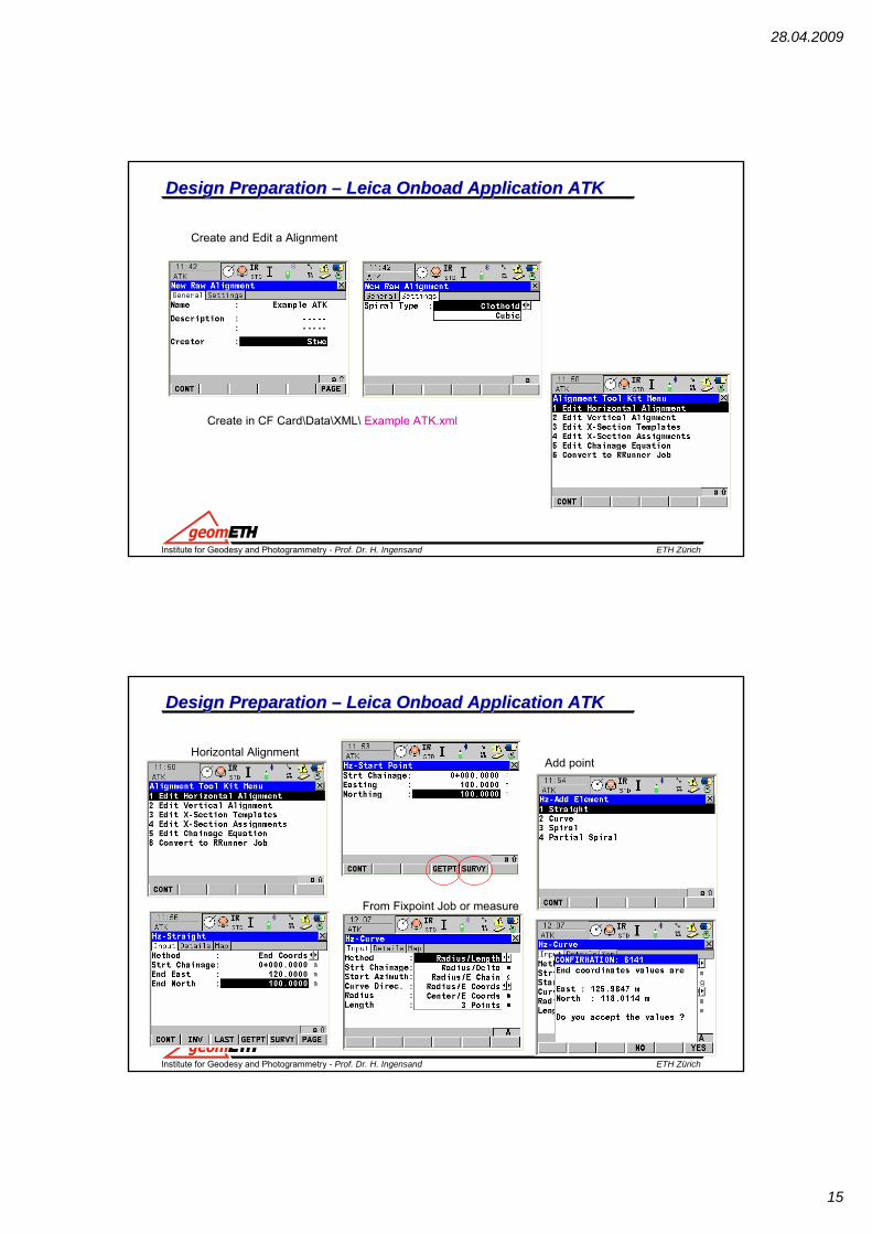
Design Design Preparation Preparation –– Leica Leica OnboadOnboad Application ATKApplication ATKThe X-Section TemplatesA X-Section gives a profile view. It requires vertical alignment or actual elevation on each chainage.The constituting elements are straight elements. The points are called vertices. You mayoptionally define slopes at the vertices most left and most right.Points are defined by:• ΔH and ΔV• ΔH and slope in percentage• ΔH and slope in ratio
The X-Section AssignmentsOne X-section is valid until a new one is defined at a chainage ahead. X-section definitioncan be at any chainage. The chainages need not necessarily correspond to chainages wherea design element starts or ends.
28.04.2009
19
ETH ZürichInstitute for Geodesy and Photogrammetry - Prof. Dr. H. Ingensand
The Chainage equationChainage Equations define adjustments for the chainage values in the horizontal alignment.These adjustments may be necessary when the horizontal alignments has been modified byinserting or removing a constituting element and the chainage in the horizontal alignmentwere not recomputed. This can be the case when editing manually or with a program whichdoes no automatic recomputation.
Convert to RoadRunner JobATK creates a log file during the conversion.
The file LandXml2Dbx.log can befound in the \Data\XML folder on the CF Card
ETH ZürichInstitute for Geodesy and Photogrammetry - Prof. Dr. H. Ingensand
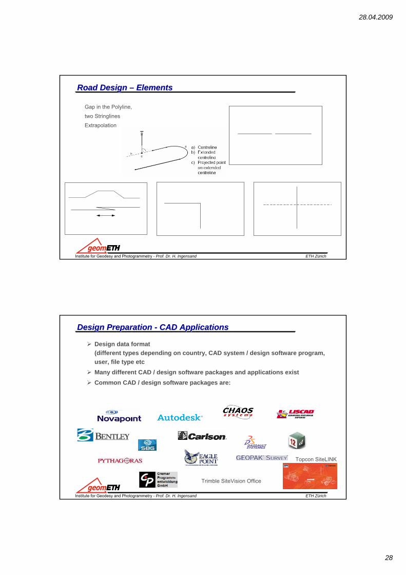
Design data format(different types depending on country, CAD system / design software program, user, file type etcMany different CAD / design software packages and applications exist Common CAD / design software packages are:
Topcon SiteLINK
Trimble SiteVision Office
28.04.2009
29
ETH ZürichInstitute for Geodesy and Photogrammetry - Prof. Dr. H. Ingensand
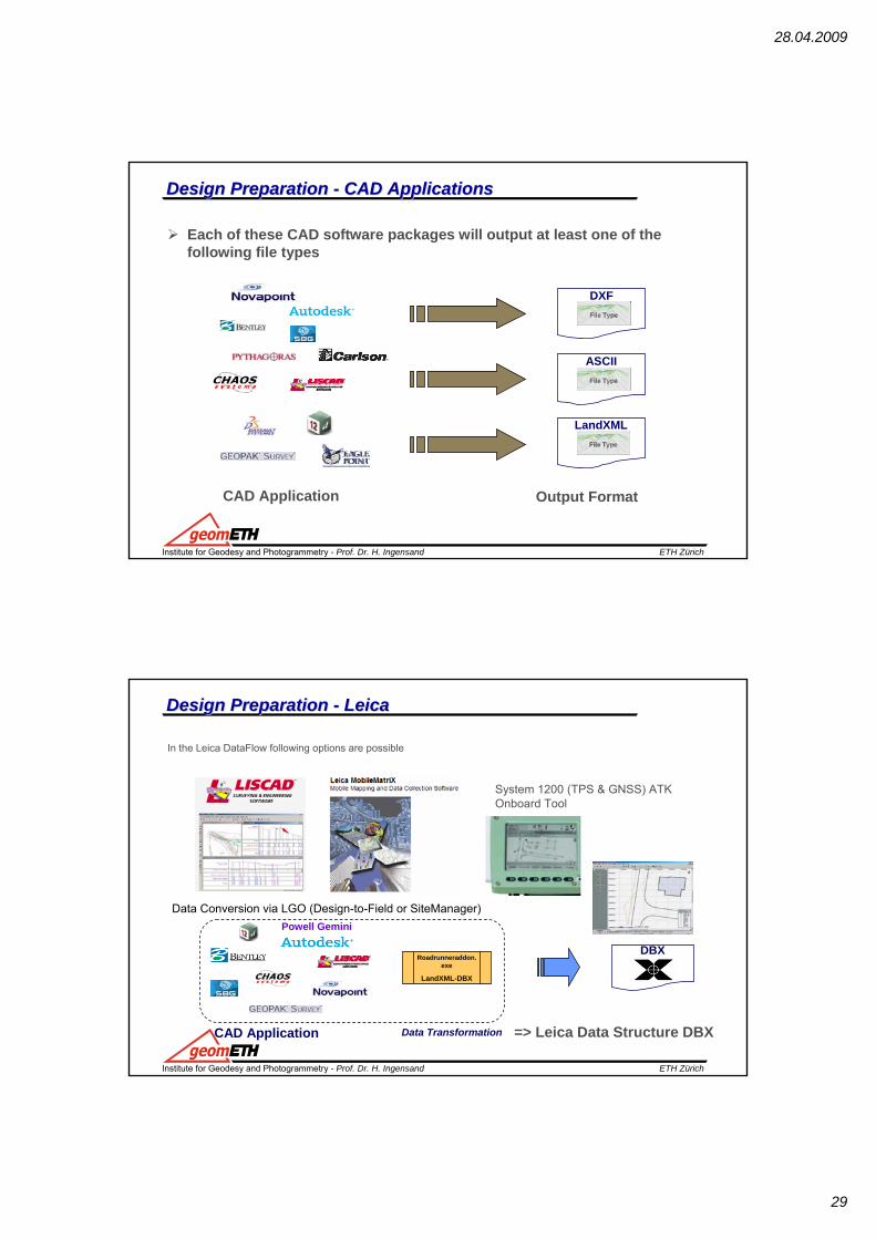
Each of these CAD software packages will output at least one of the following file types