MICHIGAN DESIGN MANUAL ROAD DESIGN CHAPTER 1 INDEX PLAN PREPARATION 1.01 DEVELOPMENT METHODS 1.01.01 References 1.01.02 General 1.01.03 Survey and Mapping Methods 1.02 PLAN SHEETS 1.02.01 Title Sheet A. Project Location B. Traffic Data C. Project Identification D. Length and Type of Work E. Consultant Identification 1.02.02 Project Information Sheet A. Utilities B. Notes Applying to Standard Plans C. Index 1.02.03 Vicinity Maps 1.02.04 Drainage Maps 1.02.05 Typical Cross Sections A. Stationing B. Scale C. Notes, Charts, Legends & Conventions D. Existing Typical Cross Section 1.02.06 Miscellaneous Details 1.02.07 Note Sheet 1.02.08 Miscellaneous Estimates 1.02.09 Legend Sheets 1.02.10 Survey Information Sheet 1.02.11 Alignment/ROW Sheets
Transcript
MICHIGAN DESIGN MANUAL
ROAD DESIGN
CHAPTER 1
INDEX
PLAN PREPARATION 1.01 DEVELOPMENT METHODS 1.01.01 References 1.01.02 General 1.01.03 Survey and Mapping Methods 1.02 PLAN SHEETS 1.02.01 Title Sheet A. Project Location B. Traffic Data C. Project Identification D. Length and Type of Work E. Consultant Identification 1.02.02 Project Information Sheet A. Utilities B. Notes Applying to Standard Plans C. Index 1.02.03 Vicinity Maps 1.02.04 Drainage Maps 1.02.05 Typical Cross Sections A. Stationing B. Scale C. Notes, Charts, Legends & Conventions D. Existing Typical Cross Section 1.02.06 Miscellaneous Details 1.02.07 Note Sheet 1.02.08 Miscellaneous Estimates 1.02.09 Legend Sheets 1.02.10 Survey Information Sheet 1.02.11 Alignment/ROW Sheets
MICHIGAN DESIGN MANUAL
ROAD DESIGN
CHAPTER 1 PLAN PREPARATION INDEX (continued) 1.02.12 Removal, Construction Plan, and Profile Sheets
A. Removal B. General
C. Guidelines 1. Plan and Profile Scale 2. Sheet Breaks 3. Information 4. Sheet Orientation and Stationing D. Quantities 1.02.13 Interchange Ramp Plan and Profile 1.02.14 Crossroad Plan and Profile 1.02.15 Detail Grades A. General B. Guidelines 1.02.16 Maintaining Traffic/Stage Construction 1.02.17 Signing Plans 1.02.18 Pavement Marking Plans 1.02.19 Miscellaneous Plans 1.02.20 Log of Borings 1.02.21 Special Details 1.03 MISCELLANEOUS 1.03.01 Order of Plan Sheets 1.03.02 Plan Preparation Conventions A. Drafting B. File Naming Conventions 1.03.03 Critical Path Method (CPM) 1.03.04 Roadway Cross Section 1.04 LOG PROJECTS 1.04.01 Preparing a Log Project 1.04.02 Earth Disturbances
MICHIGAN DESIGN MANUAL
ROAD DESIGN
CHAPTER 1
PLAN PREPARATION 1.01 DEVELOPMENT METHODS 1.01.01 (revised 11-28-2011) References A. Geometric Design Guides - Design
Division B. Guidelines for Plan Preparation – Design
Division C. Michigan Manual of Uniform Traffic
Control Devices, Current Edition D. Standard Plans and Special Details –
Design Division E. Standard Specifications for
Construction, Current Edition Existing plans for a recent project, similar in nature to the proposed project, are an excellent reference. 1.01.02 (revised 11-28-2011) General This chapter provides the information and details necessary to prepare a set of plans. The plans should contain all the information essential for bidding and constructing the project. Although innovation and creativity are encouraged in the preparation of plans, the importance of general uniformity must be emphasized. Plans should be adaptable to the diverse requirements of the Design Division and Construction Field Services Division. At the same time the plans should be a functional reference, familiar to the users. A general format should be followed by all Designers.
1.01.03 (revised 10-22-2012) Survey and Mapping Methods The choice between a ground survey, an aerial survey, a laser scanning survey, or a combination depends in part on the type and length of project, the information required, and the time schedule. Some projects may not require a survey or may require only a minor pick up survey. Old plans are valuable sources of information on these projects. Refer to Chapter 14, Procedures for Plan Preparation, for more information on surveys and mapping. 1.02 PLAN SHEETS 1.02.01 (revised 2-26-2018) Title Sheet The location map shown on the title sheet will generally be obtained from either county or city maps which are available in ProjectWise in the Reference Documents. For a particular project, a suitable map or section of one is chosen and incorporated on a standard title sheet cell. Because first impressions often sell the product, the title sheet should be neat in appearance and layout
1.02.01 (continued) Title Sheet A. Project Location The project should be located on the map and the limits (P.O.B. Stationing and P.O.E. Stationing) outlined to clearly show and stand out from the rest of the map. The map should be oriented with north to the top of the sheet and with a north arrow shown near the map. The map must show the entire project limits and other features that will easily identify the location. Preferably, at least two trunklines, names of major cross roads, and an incorporated city or village, township, and county should be shown on the location map. The town, range and section numbers should also be shown on the map. The point of beginning and the point of ending should be identified by control section, physical reference, job number, stationing, and control section mileposts. Station equations and stationing of major cross roads should also be shown. The location map should also show bridge numbers, railroad crossing numbers, and railroad companies within the project limits for both existing and proposed crossings.
1.02.01 (continued) B. Traffic Data Existing year traffic data and projected 20 year traffic data should be located on the upper left part of the title sheet. Pertinent counts including ADT, DHV, percent commercial, and the year taken are shown in tabular form. For freeway projects, the commercial DDHV should also be listed. These counts are usually present counts and projected counts. Counts are obtained from the Bureau of Transportation Planning (see Chapter 14 of this manual). The design speed and posted speed should also be shown. If the design speed changes within a project, show the various limits by stationing, cross roads, or mile points. C. Project Identification The following format should be used for identifying projects:
For filing and reference purposes, both the control section and job numbers should be shown in the appropriate blocks in the bottom margin. If the project has multiple job numbers, show them in the title block. Projects with multiple control sections should show the major control section (as programmed) first with others following in parentheses.
MICHIGAN DESIGN MANUAL
ROAD DESIGN
1.02.01 (continued) Title Sheet D. Length and Type of Work The length of the project, in hundredths of a mile, and the type of work should be shown in the bottom of the approval block. Example:
1.02.01 (continued) E. Consultant Identification If plans are being prepared by a consulting firm (prime consultant), their logo and professional engineer’s seal and signature should appear in a block above the approval block in the lower right corner. The length and type of work would then be shown above the consultant information. Sub-consultants must have their logo on the sheets they are responsible for, however, signatures are not required. If plans are being designed primarily by MDOT, but with some consultant work, the consultant must sign each sheet they are responsible for when their extent of work on the project is ten sheets or less. If the work is greater than ten sheets, the consultant must sign the first sheet and state that they are responsible for sheet #’s __ through __.
CONTRACT FOR:
DRAWING SHEET
SECT
MILES:
DEPARTMENT OF TRANSPORTATION
MICHIGAN
APPROVALSRECOMMENDED FOR APPROVAL BY:
KIRK T. STEUDLE, P.E. - DIRECTOR
, P.E. - CONSTRUCTION ENGINEER
, P.E. - PROJECT MANAGER
MICHIGAN DESIGN MANUAL
ROAD DESIGN
1.02.02 (revised 6-17-2013) Project Information Sheet The purpose of the Project Information Sheet is to show, in a convenient location, the Utilities, Notes Applying to Standard Plans, and the Plan Index.
Information on the Project Information Sheet should be project specific, current, and complete.
A. Utilities The preliminary utility list should be prefaced with and followed by the standard notes that best fit the project.
The preliminary utilities list should be from: a current survey, old plans, or the information retrieval system. It should be updated to the current date. Utility information can also be obtained from the field review section, the utility section, or the Region/TSC Utility/Permit Engineer. The final utility list shall be from the Region/TSC Utility/Permit Engineer.
The list should include the name and address of the utility, the type of utility, and a contact person, listing a phone number and address if available.
B. Notes Applying to Standard Plans Current standard plans and special details that are applicable to the project are listed on the Project Information Sheet. Special details called for on the note sheet must also be physically attached to the construction plans.
1.02.02 (continued)
Standard plans are engineering drawings showing standard details of various construction items which present the current policies of MDOT and are approved for repetitive use. In order for these drawings to become Standard Plans, they must first be approved by MDOT Administrators and have FHWA approval. The approved drawings are then made available on the MDOT Web site.
During the time these plans are being processed for approval, they are often included in the construction plans as special details.
Even though these plans are labeled "Standard Plan" in the title block, they are still considered special details when included in the construction plans. Do not change the “standard plan” label to “special detail” or remove the plan number and/or plan date on these plans. Special details are also available on the MDOT Web site.
C. Index The index is always located on the right side of the Project information sheet. Plan sheets should be arranged in the order as shown in Section 1.03.01. The index should show only the sheets included in the project. If bridges are included in the project (package project) they would be indexed "Section 2 - Bridge Plans" under the road sheets which would be referenced "Section 1 - Road Plans".
MICHIGAN DESIGN MANUAL
ROAD DESIGN
1.02.03 (revised 4-21-2014) Vicinity Maps
A vicinity map may be required for projects involving new route locations or significant right-of-way acquisitions. The map may be drawn to any recognized scale which is at least 750 scale (1"=750'), that permits showing the entire project on one plan sheet, whenever possible. A scale smaller than 750 scale is not recommended because of its inability to display detail. The level of detail may vary as needed and might include some of the following items: centerline right-of-way limits topographical features such as county
roads, city limits, lakes, rivers, railroads, drainage courses, etc.
section corners, ¼ corners, section numbers and lines, township and range, north arrow
The vicinity map may be combined with the drainage map at the discretion of the Designer. 1.02.04 (revised 1-29-2018) Drainage Maps The drainage map should show ditch lines using arrows to show the direction of flow, culverts, bridges, etc., for both existing and proposed conditions. Drainage structure sizes, both upstream and downstream, should also be shown. Show all county drains within the project limits. When a drainage course is a county drain, it should be indicated on the plans and drainage sheet. If the survey does not indicate the information, check with the MDOT Drainage Coordinator in the Environmental Section of the Bureau of Highways
1.02.04 (continued) The R.O.W width for the county drain must be shown on the plans. If the drain has no specified R.O.W. width, it should be wide enough to allow working room for maintaining the drains outside the highway R.O.W. Right of way widths should always be coordinated with the MDOT Drainage Coordinator (Utilities Design Supervising Engineer), the respective Region/TSC Drainage Coordinators(s) and verified by the County Drain Commissioner. An additional drainage sheet may be required on urban projects showing existing sewers and structures. Upon completion of the drainage design, proposed sewers, structures, and their quantities may be added to this sheet. The drainage map should also include the following items or information: The direction of flow for all existing and
proposed ditches, drains, sewers and culverts
North Arrow Names of streets, highways, county roads,
railroads, rivers, etc. Outline of the proposed road Tabulation of drainage data for all culverts
30” or greater in diameter Drainage districts For small or intermediate sized culverts the tabulation only needs to include design runoff and the drainage area. Drainage areas which are equal to or greater than 2 square miles require a more elaborate tabulation. (See MDOT Drainage Manual Section 5.3.4 for information on this tabulation.)
MICHIGAN DESIGN MANUAL
ROAD DESIGN
1.02.05 (revised 8-18-2014) Typical Cross Sections Typical cross sections are included in plans to give a graphic display of the existing and proposed cross sections of the roadway. They also describe to the contractor where each typical section will apply. All integral parts of the roadway and the roadbed should be shown including: subbase, base, surfacing, shoulders, slopes, medians, barriers, curbs, gutters, ditches, sidewalks, and so forth. A. Stationing Only the alignment required to construct the project should be shown. Stationing should be continuous with no overlaps or gaps. Stationing for superelevated sections should include the superelevation transitions. Each different condition that cannot readily be shown on one typical section should have its own section. Stationing, where that section applies, should be shown under the section. An overall Right of Way dimension shall be included. The designer should ensure that the entire project has an appropriate typical cross section. B. Scale Typical cross sections should be drawn to a scale that will allow the typical to fill the width of the page. Show the scale (horizontal and vertical) in the title block. For horizontal dimensions, use decimals, not feet and inches (only for fractional dimensions, example 12’ not 12.00’; 2.5’ not 2’-6”; 2.67’ not 2’-8”). Vertical dimensions are typically in inches (example 18” not 1’-6” or 1.5’).
1.02.05 (continued) C. Notes, Charts, Legends, & Conventions Typical section notes should be placed on the lower right corner of the first typical cross section sheet. The HMA application chart shall be shown on the first typical cross section sheet which has an HMA section. This chart shall include: the HMA mix, the rate of application, the performance grade, and remarks. All concrete typical sections should indicate the location of longitudinal joints required as detailed in the Road Sample Plans. D. Existing Typical Cross Section Often, a separate existing typical cross section is needed to show the existing conditions and removals. When the existing conditions are incorporated into the proposed cross section, they should be shown with dashed lines. Typical sections should show pavement and shoulder slopes and grading or subbase slopes. Also, show existing and proposed crown point location.
1.02.06 (revised 6-17-2013) Miscellaneous Details Occasionally, a miscellaneous detail may need to be added to address a special item or treatment on a project. The drawing is placed in the construction plans with the miscellaneous detail sheets.
1.02.07 (revised 6-17-2013) Note Sheet The purpose of the Note Sheet is to show, in a convenient location, the General Notes applying to the project.
1.02.08 (revised 10-22-2012) Miscellaneous Estimates The miscellaneous estimates section is for listing all pay items that do not appear elsewhere in the plans. This estimate usually includes the following items: Contractor Staking Concrete and HMA Quality Initiative Project Cleanup Erosion and Sedimentation Control Items Slope Restoration Items Subgrade Correction Items Maintaining Traffic Items Pavement Joints Pavement Markings and Signs if separate
sheets are not part of the plans Items are not limited to those shown above nor are these items always shown on the miscellaneous estimate sheet. If pay items can conveniently and clearly be shown on the plans, there is no need to include them in the miscellaneous estimate sheet. Quantities shown in the miscellaneous estimate area should be separated by job number and local participation, when applicable. If a project includes several Act 51 participating cities, a column for quantities in each city will be necessary.
MICHIGAN DESIGN MANUAL
ROAD DESIGN
1.02.09 Legend Sheets The legend sheet shows all the standard symbols and conventions used in the plans. These include symbols for drainage, utilities, real estate, topography, paving and removals. A separate legend sheet can be included in most major projects, however, the necessary information can also be shown on construction plan sheets and/or removal sheets. If the legend crowds or clutters the plan sheets, a separate legend sheet would be in order. 1.02.10 (revised 10-22-2012) Survey Information Sheet Beginning with Datum Notes, this sheet lists bench marks and horizontal control points, with witnesses and coordinates. Horizontal alignment points (P.C., P.I., P.T., and P.O.T.) found or set by the surveyor and government corners are also included.
1.02.11 (revised 10-22-2012) Alignment/ROW Sheets An Alignment/ROW sheet should be incorporated with the plan set. The Alignment/ROW sheet should show the following: All alignments pertinent to the project:
existing legal and proposed construction. Alignments station-referenced to the Public Land Survey System, Section, Township and Range, showing the PLSS corners with bearing and distance ties to the intersections of the alignments and the government lines. These ties shall only appear on the Alignment/ROW Sheets within the plan set.
ROW lines dimensioned from the legal alignment from which the lines were established.
Curve data for all project alignments shall be shown on the Alignment/ROW sheet only. Curve data shall be placed once, on the Alignment/ROW sheet on which the curve’s P.I. is located.
Subdivision plat information shall be shown on the Alignment/ROW sheets, as well as on the Removal and Construction sheets.
MDOT parcel numbers and property boundary information shall be shown on the Alignment/ROW sheets only.
Proposed Right of Way dimensions Coordinates for ROW Monuments, P.I.'s,
P.C.'s, and P.T.'s North Arrow
MICHIGAN DESIGN MANUAL
ROAD DESIGN
1.02.12 (revised 1-20-2015) Removal, Construction Plan, and Profile Sheets A. Removal Separate Removal Sheets should be considered depending on the type, location, and complexity of the project. Removal Sheets are almost always needed for projects in congested urban areas. An early determination should be made whether or not to include removal items on the construction plan sheets. If this would cause the plans to become cluttered and difficult to read, then separate Removal Sheets should be used. The Removal Sheets should show all existing topography within the project limits. All items for removal will be indicated on these sheets. Once it has been determined that an item is to be removed and it has been indicated on the Removal Sheet, the item should no longer appear on the construction plan sheet. Slope stake lines should be shown to determine removal limits. The edges of proposed pavement or back of curb may also be beneficial in determining removals. Subdivision plat information shall be shown on the Removal Sheets. The Removal Sheets shall only show the alignment required to construct the project.
1.02.12 B. General Construction plan and profile sheets are the "meat" of a set of plans. Plan sheets are “overhead” maps or pictorial representations of the project to be constructed. Plan sheets indicate what items need to be removed, replaced, relocated, reconstructed, constructed, or adjusted. Plan sheets must be clear, complete, correct, and uniform to convey to the contractor how to construct the project and what materials will be needed. P.C., P.I., and P.T. Station labels shall be shown for the alignment required to construct the project. If the scope of work involves a significant amount of drainage and utility renovation or removal, separate plan sheets may be required for each phase of construction (removal, utility and drainage, and construction). Profile sheets show existing elevations and proposed elevations of the finished construction project. They also show drainage details including existing and proposed ditch elevation, top of curbs, drainage structures, sewers, and other utility information. Profile sheets should also show grading information, such as front and back slopes, peat location and treatment, and excavation and embankment quantities. Profile sheets may not be required on all projects, such as when the grade is not changing, or it is changing at a uniform rate.
MICHIGAN DESIGN MANUAL
ROAD DESIGN
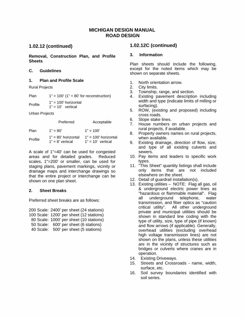
1.02.12 (continued) Removal, Construction Plan, and Profile Sheets C. Guidelines 1. Plan and Profile Scale
Rural Projects
Plan 1" = 100’ (1” = 80’ for reconstruction)
Profile 1" = 100' horizontal 1" = 10' vertical
Urban Projects
Preferred Acceptable
Plan 1" = 80' 1" = 100'
Profile 1” = 80’ horizontal 1” = 8’ vertical
1" = 100' horizontal 1" = 10' vertical
A scale of 1"=40' can be used for congested areas and for detailed grades. Reduced scales, 1"=200' or smaller, can be used for staging plans, pavement markings, vicinity or drainage maps and interchange drawings so that the entire project or interchange can be shown on one plan sheet. 2. Sheet Breaks Preferred sheet breaks are as follows: 200 Scale: 2400' per sheet (24 stations) 100 Scale: 1200' per sheet (12 stations) 80 Scale: 1000' per sheet (10 stations) 50 Scale: 600' per sheet (6 stations) 40 Scale: 500' per sheet (5 stations)
1.02.12C (continued) 3. Information Plan sheets should include the following, except for the noted items which may be shown on separate sheets. 1. North orientation arrow. 2. City limits. 3. Township, range, and section. 4. Existing pavement description including
width and type (indicate limits of milling or surfacing).
5. ROW, (existing and proposed) including cross roads.
6. Slope stake lines. 7. House numbers on urban projects and
rural projects, if available. 8. Property owners names on rural projects,
when available. 9. Existing drainage, direction of flow, size,
and type of all existing culverts and sewers.
10. Pay items and leaders to specific work types.
11. "This Sheet" quantity listings shall include only items that are not included elsewhere on the sheet.
12. Detail of guardrail installation(s). 13. Existing utilities – NOTE: Flag all gas, oil
& underground electric power lines as "hazardous or flammable material". Flag all underground telephone, water transmission, and fiber optics as “caution critical utility”. All other underground private and municipal utilities should be shown in standard line coding with the type of utility, size, type of pipe (if known) and flow arrows (if applicable). Generally, overhead utilities (excluding overhead high voltage transmission lines) are not shown on the plans, unless these utilities are in the vicinity of structures such as bridges or culverts where cranes are in operation.
14. Existing Driveways. 15. Streets and Crossroads - name, width,
surface, etc. 16. Soil survey boundaries identified with
soil series.
MICHIGAN DESIGN MANUAL
ROAD DESIGN
1.02.12C (continued) Removal, Construction Plan, and Profile Sheets Profile sheets shall show the following when applicable: 1. Proposed plan and ditch grade (include
curb grades). 2. Type lines (showing front slope, back
slope, ditch information, superelevation, and transitions, etc.)
3. Crossroad or street profiles 4. Sidewalk profiles and/or top of curb
grade profiles. 5. Existing ground profile and ground
points - side profiles. 6. Vertical Curves a. K-value b. P.I. station and curve length 7. Tangent Grades. 8. Temporary roads. 9. Water table information 10. Rock, peat, muck, undercut locations,
and treatments. 11. Cross culverts 12. Existing and proposed underground
13. Existing drainage structures and pipes - dashed lines.
14. Proposed drainage structures and sewers - solid lines.
15. Proposed flow line elevations to nearest hundredths of a foot.
16. Existing (surveyed) flow line elevations to nearest hundredths of a foot. Estimated existing flow lines should be shown to the nearest tenth of a foot.
17. Earthwork limits and quantities. 18. Other miscellaneous quantities. 19. Station equations.
1.02.12C (continued) Profile sheets should reference the alignment required to construct the project or plan grade profile line showing both existing grade and proposed grade. Side profiles should also be indicated, usually a set distance left and right of the alignment, i.e., 30 feet left and 30 feet right. Rural projects would use the side profiles to plot existing and proposed ditch grades; urban projects to indicate top of curb grades or sometimes gutter or sidewalk grades. Rural projects also usually include ground points at even stations and usually 100 feet left and right of centerline. These points give the designer an indication of the lay of the land in the project area but certainly do not replace the need for cross sections. 4. Sheet Orientation and Stationing Plan sheets should be set up to avoid breaking at important design features such as interchanges, intersections, or curves starting or ending at the beginning or end of a sheet. Sheets on curves should be angled to produce a balanced sheet; the tangent sections should be near the center of the plan sheet. Stationing should be from left to right, should not be overlapped sheet to sheet, and should be the same as the profile stationing. Plan and profile stationing should ideally begin and end with a station multiple of 100 feet (e.g. station 3+00 or 6+00). Stations will be based on hundreds of feet. Each “tick” mark is identified as follows: 1, 2, 3, etc. Alignments will be "ticked" and labeled at 100 foot intervals.
MICHIGAN DESIGN MANUAL
ROAD DESIGN
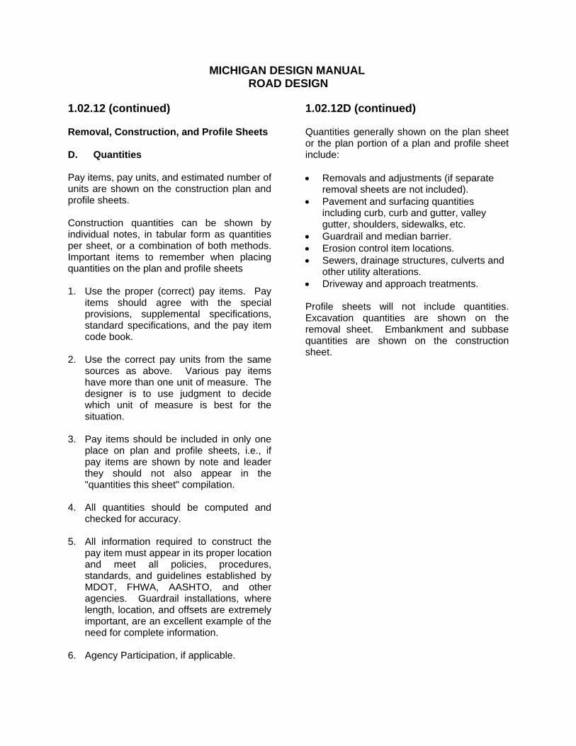
1.02.12 (continued) Removal, Construction, and Profile Sheets D. Quantities Pay items, pay units, and estimated number of units are shown on the construction plan and profile sheets. Construction quantities can be shown by individual notes, in tabular form as quantities per sheet, or a combination of both methods. Important items to remember when placing quantities on the plan and profile sheets 1. Use the proper (correct) pay items. Pay
items should agree with the special provisions, supplemental specifications, standard specifications, and the pay item code book.
2. Use the correct pay units from the same
sources as above. Various pay items have more than one unit of measure. The designer is to use judgment to decide which unit of measure is best for the situation.
3. Pay items should be included in only one
place on plan and profile sheets, i.e., if pay items are shown by note and leader they should not also appear in the "quantities this sheet" compilation.
4. All quantities should be computed and
checked for accuracy. 5. All information required to construct the
pay item must appear in its proper location and meet all policies, procedures, standards, and guidelines established by MDOT, FHWA, AASHTO, and other agencies. Guardrail installations, where length, location, and offsets are extremely important, are an excellent example of the need for complete information.
6. Agency Participation, if applicable.
1.02.12D (continued) Quantities generally shown on the plan sheet or the plan portion of a plan and profile sheet include: Removals and adjustments (if separate
removal sheets are not included). Pavement and surfacing quantities
including curb, curb and gutter, valley gutter, shoulders, sidewalks, etc.
Guardrail and median barrier. Erosion control item locations. Sewers, drainage structures, culverts and
other utility alterations. Driveway and approach treatments. Profile sheets will not include quantities. Excavation quantities are shown on the removal sheet. Embankment and subbase quantities are shown on the construction sheet.
MICHIGAN DESIGN MANUAL
ROAD DESIGN
1.02.13 (revised 10-22-2012) Interchange Ramp Plan and Profile Each interchange ramp should be shown on a separate plan and profile sheet(s). The format for ramp sheets is the same as those for mainline plan and profile sheets. Care should be exercised in setting the grades on ramps, especially where the ramp, the mainline, and the crossroad are close together or connected. Detail grades of the gore area are always needed. Detail grades for crossroad intersection are sometimes necessary to ensure proper grades. (See Section 1.02.15.) 1.02.14 (revised 10-22-2012) Crossroad Plan and Profile If a project involves extensive work on crossroads, including relocation or changes in elevation, separate plan and profile sheets should be included for the crossroads. Again mainline plan and profile guidelines should be followed when setting up crossroad plan and profile sheets. Particular care should be exercised at intersections of crossroads and trunklines. Grades should be set to favor the through roadway, usually the trunkline, but a smooth ride from the crossroad across the trunkline should also be considered. Detail grades are very useful in determining good grades through intersections and their use should always be considered when reconstructing major intersections, especially in urban areas. (See Section 1.02.15.)
1.02.15 (revised 10-22-2012) Detail Grades A. General Detail grades are exaggerated drawings that help the designer to set good grades through problem areas. Detail grades should be considered whenever two roadways intersect on a project with grade changes. Problem areas may include ramps merging with or diverging from the mainline, gore areas, ramp intersections with crossroads, mainline and crossroad intersections, major driveways, auxiliary lanes, and many others. Detail grades will help the designer to: 1. Determine a smooth, rideable grade
through the problem area. 2. Determine good drainage throughout the
intersection. 3. Avoid excessive crown drops. 4. Avoid excessive cross slopes that could
exceed recommended maximum break over slopes.
MICHIGAN DESIGN MANUAL
ROAD DESIGN
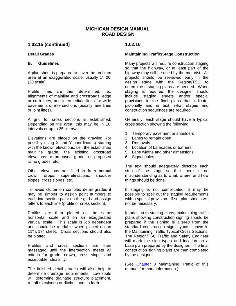
1.02.15 (continued) Detail Grades B. Guidelines A plan sheet is prepared to cover the problem area at an exaggerated scale, usually 1"=20' (20 scale). Profile lines are then determined; i.e., alignments of mainline and crossroads, edge or curb lines, and intermediate lines for wide pavements or intersections (usually lane lines or joint lines). A grid for cross sections is established. Depending on the area, this may be in 10' intervals or up to 25' intervals. Elevations are placed on the drawing, (or possibly using X and Y coordinates) starting with the known elevations, i.e., the established mainline grade, the existing crossroad elevations or proposed grade, or proposed ramp grades, etc. Other elevations are filled in from normal crown drops, superelevations, shoulder slopes, cross slopes, etc. To avoid clutter on complex detail grades it may be simpler to assign point numbers to each intersection point on the grid and assign letters to each line (profile or cross section). Profiles are then plotted on the same horizontal scale and on an exaggerated vertical scale. This scale is job dependent and should be readable when placed on an 11" x 17" sheet. Cross sections should also be plotted. Profiles and cross sections are then massaged until the intersection meets all criteria for grade, crown, cross slope, and acceptable rideability. The finished detail grades will also help to determine drainage requirements. Low spots will determine drainage structure placement, runoff to culverts or ditches and so forth.
1.02.16 Maintaining Traffic/Stage Construction Many projects will require construction staging so that the highway, or at least part of the highway may still be used by the motorist. All projects should be reviewed early in the design stage with the Region/TSC to determine if staging plans are needed. When staging is required, the designer should include staging sheets and/or special provisions in the final plans that indicate, pictorially and in text, what stages and construction sequences are required. Generally, each stage should have a typical cross section showing the following: 1. Temporary pavement or shoulders 2. Lanes to remain open 3. Removals 4. Location of barricades or barriers 5. Lane widths and other dimensions 6. Signal poles The text should adequately describe each step of the stage so that there is no misunderstanding as to what, where, and how things should be done. If staging is not complicated, it may be possible to spell out the staging requirements with a special provision. If so, plan sheets will not be necessary. In addition to staging plans, maintaining traffic plans showing construction signing should be prepared if the signing is altered from the standard construction sign layouts shown in the Maintaining Traffic Typical Cross Sections. The Region/TSC Traffic and Safety Engineer will mark the sign types and location on a base plan prepared by the designer. The final construction signing plans are then completed by the designer. (See Chapter 8 Maintaining Traffic of this manual for more information.)
MICHIGAN DESIGN MANUAL
ROAD DESIGN
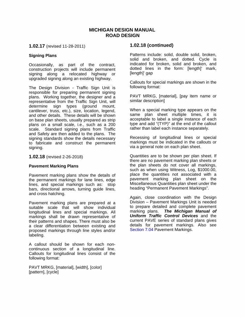
1.02.17 (revised 11-28-2011) Signing Plans Occasionally, as part of the contract, construction projects will include permanent signing along a relocated highway or upgraded signing along an existing highway. The Design Division - Traffic Sign Unit is responsible for preparing permanent signing plans. Working together, the designer and a representative from the Traffic Sign Unit, will determine sign types (ground mount, cantilever, truss, etc.), size, location, legend, and other details. These details will be shown on base plan sheets, usually prepared as strip plans on a small scale, i.e., such as a 200 scale. Standard signing plans from Traffic and Safety are then added to the plans. The signing standards show the details necessary to fabricate and construct the permanent signing. 1.02.18 (revised 2-26-2018) Pavement Marking Plans Pavement marking plans show the details of the permanent markings for lane lines, edge lines, and special markings such as: stop bars, directional arrows, turning guide lines, and cross hatching. Pavement marking plans are prepared at a suitable scale that will show individual longitudinal lines and special markings. All markings shall be drawn representative of their patterns and shapes. There must also be a clear differentiation between existing and proposed markings through line styles and/or labeling. A callout should be shown for each non-continuous section of a longitudinal line. Callouts for longitudinal lines consist of the following format: PAVT MRKG, [material], [width], [color] [pattern], [cycle]
1.02.18 (continued) Patterns include: solid, double solid, broken, solid and broken, and dotted. Cycle is indicated for broken, solid and broken, and dotted lines in the form: [length]’ mark, [length]’ gap Callouts for special markings are shown in the following format: PAVT MRKG, [material], [pay item name or similar description] When a special marking type appears on the same plan sheet multiple times, it is acceptable to label a single instance of each type and add “(TYP)” at the end of the callout rather than label each instance separately. Recessing of longitudinal lines or special markings must be indicated in the callouts or via a general note on each plan sheet. Quantities are to be shown per plan sheet. If there are no pavement marking plan sheets or the plan sheets do not cover all markings, such as when using Witness, Log, $1000.00, place the quantities not associated with a pavement marking plan sheet on the Miscellaneous Quantities plan sheet under the heading “Permanent Pavement Markings”. Again, close coordination with the Design Division – Pavement Markings Unit is needed to prepare detailed and complete pavement marking plans. The Michigan Manual of Uniform Traffic Control Devices and the current PAVE series of standard plans gives details for pavement markings. Also see Section 7.04 Pavement Markings.
MICHIGAN DESIGN MANUAL
ROAD DESIGN
1.02.19 (revised 11-28-2011) Miscellaneous Plans Occasionally, a project may require traffic signal plans, municipal utility plans, wetland mitigation plans or other miscellaneous plan sheets. Traffic signal plans are prepared by the Operations Field Services Division - Traffic Signal Unit. Municipal utility plans, such as water mains, street lighting, sanitary sewers, etc. would be prepared by or coordinated through the Utility Section of the Design Division. Wetland mitigation plans are coordinated with the Roadside Development Unit of the Design Division. 1.02.20 (revised 11-28-2011) Log of Borings Many construction projects require numerous soil borings, pavement coring, and other geotechnical information. Soil borings and cores are needed for a variety of reasons, including but not limited to: 1. Subgrade information 2. Pavement structure type and depth 3. Foundation (signs, trusses, retaining
walls, bridges, etc.) information 4. Proposed sewer, culvert, and other
underground utility information 5. Location of water table 6. Signal poles When there are only a few borings required on a project, they can be shown on the plan or profile sheet where they are located. In most cases, however, separate log of boring sheets should be prepared. These sheets show the number and location of the boring and a sketch which includes the depth and a description of the material encountered. The Design Division’s Guidelines for Plan Preparation have a sample soil boring sheet which is a good reference when preparing log of borings plan sheets.
1.02.20 (continued) Log of Borings Information that needs to be supplied along with the Borings are: date the boring was taken, who performed the boring, and the level of the water table (or "dry"). Construction Field Services Division and the Region/TSC Soils Engineer will analyze the boring information and make recommendations regarding pavement structure, subbase requirements, subgrade undercutting, foundation recommendations, sewer and culvert trench undercutting, bedding, dewatering needs, and other special treatments. 1.02.21 (revised 10-22-2012) Special Details Special Detail plan sheets are used to show project specific items and details not covered by the standard plans. They are located in a folder in ProjectWise for MDOT internal access. These details are typically draft versions of new or revised standard plans awaiting final approval. These special detail sheets should be included in the final set of construction plans. Modified Special Detail sheets may also be prepared by the designer to show other necessary details not covered by a standard plan or special detail provided by the Standards Unit. These may include gore details, guardrail installations, surfacing details and transitions, modifications of standard items, drainage details and so forth. See Section 1.02.02B for more information.
1.03 MISCELLANEOUS 1.03.01 (revised 10-17-2016) Order of Plan Sheets Plans should be assembled in the following order:
Title Project Information Legend ROW Vicinity/Drainage Map Note Miscellaneous Quantities Typical Cross Sections Miscellaneous Details Survey Information Alignment Removal, Construction, Drainage & Profile Water Main & Sanitary Sewer Maintaining Traffic/Construction Staging Plans Detail Grades Culvert Plans Detention Basin Details Wetland Mitigation Plans Rest Area/Landscape Plans Permanent Signing Plans Pavement Marking Plans Lighting Plans ITS Plans Signal Plans Log of Borings Special Details Bridge Plans
Removal, construction, drainage if needed, and profile sheets should be arranged in this order according to station limits. Only the sheets included in a set of plans should appear in the index of the title sheet.
1.03.02 (revised 3-16-2015) Plan Preparation Conventions A. Drafting
See the Sample Plans for examples of drafting conventions, symbols, line weights, etc. to use in preparing plans. B. File Naming Conventions 1. Plan and Proposal Milestones See Chapter 3 of Design Submittal Requirements. 2. Reference Information Documents (RID) See Section 14.65 and Design Submittal Requirements.
1.03.03 (revised 11-28-2011) Critical Path Method (CPM) Critical Path diagrams indicate construction events, the sequence of each event, the time required to complete each event, and which events become "critical" to the completion of the project. The designer may be asked to complete a critical path diagram for all but the most simplistic projects. Critical path diagrams are not a part of the plans, but are valuable for setting construction completion dates, open to traffic dates and other intermediate dates. Contractors interested in bidding the project can receive the CPM prepared by the designer, but are encouraged to prepare their own critical path diagrams. CPM's should not be given to contractors without a disclaimer worded similar to the following: B.P.I.A. Company 123 Money Street Mission Model, MI 48917 Attached is a copy of the critical path and computer printout that you requested for the subject project. The critical path information was used as one of the aids in arriving at the final completion date and/or interim completion dates. It is not officially part of the plans and any errors or omissions will not relieve the contractor from meeting the dates set in the progress schedule in the proposal. Critical paths are very important for high impact and expedited projects. The CPM will show which items or events need to be expedited to complete the project. Early and late start and finish dates, seasonal limitations, holiday and special event shutdowns, and ordering and delivery of materials all enter into the formulation of the path.
1.03.03 (continued) When preparing the CPM, it is important to consider the length of the work week. With weather being a consideration, a four-day work week can be used on normal projects. On expedited projects, however, a five or even six-day work week may be appropriate. Information on times for construction events, sequences, etc. is available from Construction Field Services Division. The designer should work closely with Construction Field Services Division and/or the project engineer when preparing the CPM. 1.03.04 (revised 10-22-2012) Roadway Cross Sections Roadway cross sections are very valuable to the designer. They are one of the main items used to design the project. Cross sections are used by the designer to visualize what the roadway will look like in the field. Roadway cross sections show the existing roadway conditions. They are used to determine earthwork, draw slope stake lines, determine right of way needs, fit proposed to existing, determine driveway and crossroad grades, determine clearing and removal limits, determine drainage requirements, set front and back slopes, and determine much more information needed to design the project. Cross sections should be plotted for all projects with grade and slope changes. Exaggerated cross sections can be very helpful in setting curb grades on urban projects. The roadway cross sections are not included in the plans but should be sent to the project engineer before the project is under construction. The sections can be very informative to the construction personnel and, many times, help to explain the design shown on the plans.
MICHIGAN DESIGN MANUAL
ROAD DESIGN
1.04 LOG PROJECTS 1.04.01 (revised 6-17-2013) Preparing a Log Project Most designs for construction projects will be prepared using full size plan sheets. Occasionally a project may be very straightforward and uncomplicated. In such cases, the design can be completed with sketches and a written narrative. Such a design is called a "Log Project". In a log project the title sheet, typical cross sections, and details are prepared on 8½” x 11" sheets. The work plan (log of project), including pay items, is written in narrative form describing what and where construction operations will occur. Locations are referenced by station which is often obtained by a distance measuring device or from old plans, rather than an accurate survey. Existing right of way maps, reduced to 8½” x 11" are sometimes included in the log. Log projects provide a simple design when specific detail or accuracy is not required. Because of the complexity and the need for detail in most major road design projects, the use of log plans are not very common. In general, projects with estimated construction cost exceeding $2.5 million should be prepared using full size plan sheets.
1.04.01 (continued) Log projects include much of the same information that is in a normal plan project, including utilities, standard notes, applicable standard plans and special details, typical cross sections, maintaining traffic details, staging, pavement markings, signing, and so forth. All project detail sheets and the descriptive write-up are prepared on 8½” x 11" sheets and should be included with the supplemental specifications, special provisions, and other bid documents in the proposal format. The sheets for log projects should be assembled in the same general order listed for plan sheet projects as they apply for the log project (see Section 1.03.01). If a sheet index is listed, it should be listed on a separate sheet following the title sheet. Generally the log of project write up precedes the typical cross sections. However the reverse may apply as necessary to provide a logical sequencing of information. Log projects are required to include Pay Items for Monument Preservation, Monument Preservation Vertical, Monument Box, Protect Corners, and Monument Box Adjust.
MICHIGAN DESIGN MANUAL
ROAD DESIGN
1.04.02 (added 10-20-2008) Earth Disturbances Information related to soil erosion and sedimentation controls for an earth disturbance, which is normally included in a full size set of plans, is sometimes also required in a log project. An earth disturbance is a human-made change in the natural cover or topography of land, including cut and fill activities, which may result in or contribute to soil erosion and subsequent sedimentation of the waters of the state. Earth disturbances in log projects, which contain work items such as culvert extensions or shoulder widening within the Right-of-Way or within the limits of a grading permit, will require inclusion of SESC measures. If an earth disturbance occurs within 500 feet of a lake or stream, or is one acre or greater in area, the following twelve elements are required to be included in the log documents. These elements constitute an earth change plan as outlined in R 323.1703 of the State Administrative Rules (Part 17). 1. A scaled drawing of the work site 2. Township, Range & Section 3. A site location sketch 4. Proximity to lakes and streams
(Distance and direction to) 5. Predominant land features (USGS
description) 6. A slope description (Typicals or copy of
contour maps) 7. General soil types (Borings not required,
just description of general soil types.) 8. Limits of earth change (Using slope
stake lines and ROW lines) 9. Drainage features or dewatering
operations (Culverts, sewers or water diversions)
10. Timing and sequence of earth change (Reference to Construction Progress Schedule)
11. Description and location of SESC measures (Show key numbers in the log)
12. Maintenance plan for SESC measures (See SESC Manual for maintenance of key items.)
1.04.02 (continued) Preferably, SESC measures should be included in the proposal using key numbers from the SESC Manual. Otherwise, plan notes can be used. If a ditching operation utilizes a project log, language in the proposal should refer to the Maintenance Division's guidance document for this item of work (#12300), a copy of which is also included in the latest SESC manual. Refer to Section 2.05 for detailed information on including SESC measures on plans. Contact your environmental coordinator or region resource specialist if you have any additional questions regarding earth disturbances and earth change plans.