122
5PX-28199-11 LIT-11626-16-36 XV1700PCR XV1700PCRC OWNER’S MANUAL
| Date post: | 07-Feb-2018 |
| Category: |
Documents |
| Upload: | truongnguyet |
| View: | 216 times |
| Download: | 3 times |

5PX-28199-11LIT-11626-16-36
XV1700PCRXV1700PCRC
OWNER’S MANUAL

EAU03438
EAU00002 INTRODUCTION
Congratulations on your purchase of the Yamaha XV1700PC/XV1700PCC. Thismodel is the result of Yamaha’s vast experience in the production of fine sporting,touring, and pacesetting racing machines. It represents the high degree of crafts-manship and reliability that have made Yamaha a leader in these fields.
This manual will give you an understanding of the operation, inspection, and basicmaintenance of this motorcycle. If you have any questions concerning the operationor maintenance of your motorcycle, please consult a Yamaha dealer.
The design and manufacture of this Yamaha motorcycle fully comply with the emis-sions standards for clean air applicable at the date of manufacture. Yamaha has metthese standards without reducing the performance or economy of operation of themotorcycle. To maintain these high standards, it is important that you and yourYamaha dealer pay close attention to the recommended maintenance schedules andoperating instructions contained within this manual.

EAU00003IMPORTANT MANUAL INFORMATION
Particularly important information is distinguished in this manual by the following notations:
The Safety Alert Symbol means ATTENTION! BECOME ALERT! YOUR SAFETY ISINVOLVED!
WARNING Failure to follow WARNING instructions could result in severe injury or death to themotorcycle operator, a bystander or a person inspecting or repairing the motorcycle.
CAUTION: A CAUTION indicates special precautions that must be taken to avoid damage to themotorcycle.
NOTE: A NOTE provides key information to make procedures easier or clearer.
NOTE:_
● This manual should be considered a permanent part of this motorcycle and should remainwith it even if the motorcycle is subsequently sold.
● Yamaha continually seeks advancements in product design and quality. Therefore, whilethis manual contains the most current product information available at the time of printing,there may be minor discrepancies between your motorcycle and this manual. If you haveany questions concerning this manual, please consult your Yamaha dealer.
_

IMPORTANT MANUAL INFORMATIONEW000000
WARNING_
PLEASE READ THIS MANUAL AND THE “YOU AND YOUR MOTORCYCLE: RIDINGTIPS” BOOKLET CAREFULLY AND COMPLETELY BEFORE OPERATING THIS MOTOR-CYCLE. DO NOT ATTEMPT TO OPERATE THIS MOTORCYCLE UNTIL YOU HAVE AT-TAINED ADEQUATE KNOWLEDGE OF ITS CONTROLS AND OPERATING FEATURESAND UNTIL YOU HAVE BEEN TRAINED IN SAFE AND PROPER RIDING TECHNIQUES.REGULAR INSPECTIONS AND CAREFUL MAINTENANCE, ALONG WITH GOOD RIDINGSKILLS, WILL ENSURE THAT YOU SAFELY ENJOY THE CAPABILITIES AND THE RELI-ABILITY OF THIS MOTORCYCLE. _

IMPORTANT MANUAL INFORMATION
AFFIX DEALER
LABEL HERE
EAU04247
XV1700PCR/XV1700PCRCOWNER’S MANUAL
©2002 by Yamaha Motor Corporation, U.S.A.1st edition, June 2002
All rights reserved.Any reprinting or unauthorized usewithout the written permission of
Yamaha Motor Corporation, U.S.A.is expressly prohibited.
Printed in Japan.P/N LIT-11626-16-36

TABLE OF CONTENTS
1 SAFETY INFORMATION 1
2 DESCRIPTION 2
3 INSTRUMENT AND CONTROL FUNCTIONS 3
4 PRE-OPERATION CHECKS 4
5 OPERATION AND IMPORTANT RIDING POINTS 5
6 PERIODIC MAINTENANCE AND MINOR REPAIR 6
7 MOTORCYCLE CARE AND STORAGE 7
8 SPECIFICATIONS 8
9 CONSUMER INFORMATION 9
INDEX
EAU00009

SAFETY INFORMATION
1
Safe riding .......................................................................................... 1-1Protective apparel .............................................................................. 1-3Modifications ...................................................................................... 1-3Loading and accessories ................................................................... 1-3Gasoline and exhaust gas.................................................................. 1-5Location of important labels .............................................................. 1-7
1
1-1
EAU04193
1-SAFETY INFORMATION
MOTORCYCLES ARE SINGLE TRACK VEHICLES. THEIR SAFE USE AND OPERATION AREDEPENDENT UPON THE USE OF PROPER RIDING TECHNIQUES AS WELL AS THE EXPERTISEOF THE OPERATOR. EVERY OPERATOR SHOULD KNOW THE FOLLOWING REQUIREMENTSBEFORE RIDING THIS MOTORCYCLE.HE OR SHE SHOULD:1. OBTAIN THOROUGH INSTRUCTIONS FROM A COMPETENT SOURCE ON ALL ASPECTS OF
MOTORCYCLE OPERATION.2. OBSERVE THE WARNINGS AND MAINTENANCE REQUIREMENTS IN THE OWNER’S MANU-
AL.3. OBTAIN QUALIFIED TRAINING IN SAFE AND PROPER RIDING TECHNIQUES.4. OBTAIN PROFESSIONAL TECHNICAL SERVICE AS INDICATED BY THE OWNER’S MANUAL
AND/OR WHEN MADE NECESSARY BY MECHANICAL CONDITIONS.
Safe riding
1. Always make pre-operation checks. Careful checks may help prevent an accident.2. This motorcycle is designed to carry the operator and a passenger.3. The failure of motorists to detect and recognize motorcycles in traffic is the predominating cause of
automobile/motorcycle accidents. Many accidents have been caused by an automobile driver whodid not see the motorcycle. Making yourself conspicuous appears to be very effective in reducing thechance of this type of accident.
Therefore:a. Wear a brightly colored jacket.b. Use extra caution when you are approaching and passing through intersections, since intersec-
tions are the most likely places for motorcycle accidents to occur.c. Ride where other motorists can see you. Avoid riding in another motorist’s blind spot.

SAFETY INFORMATION
1
1-2
4. Many accidents involve inexperienced operators. In fact, many operators who have been involved inaccidents do not even have a current motorcycle license.a. Make sure that you are qualified and that you only lend your motorcycle to other qualified opera-
tors.b. Know your skills and limits. Staying within your limits may help you to avoid an accident.c. We recommend that you practice riding your motorcycle where there is no traffic until you have
become thoroughly familiar with the motorcycle and all of its controls.5. Many accidents have been caused by error of the motorcycle operator. A typical error made by the
operator is veering wide on a turn due to EXCESSIVE SPEED or undercornering (insufficient leanangle for the speed).a. Always obey the speed limit and never travel faster than warranted by road and traffic conditions.b. Always signal before turning or changing lanes. Make sure that other motorists can see you.
6. The posture of the operator and passenger is important for proper control.a. The operator should keep both hands on the handlebar and both feet on the operator footrests
during operation to maintain control of the motorcycle.b. The passenger should always hold onto the operator, the seat strap or grab bar, if equipped, with
both hands and keep both feet on the passenger footrests.c. Never carry a passenger unless he or she can firmly place both feet on the passenger footrests.
7. Never ride under the influence of alcohol or other drugs.8. This motorcycle is designed for on-road use only. It is not suitable for off-road use.
SAFETY INFORMATION
1
1-3
Protective apparel
The majority of fatalities from motorcycle accidents are the result of head injuries. The use of a safetyhelmet is the single most critical factor in the prevention or reduction of head injuries.1. Always wear an approved helmet.2. Wear a face shield or goggles. Wind in your unprotected eyes could contribute to an impairment of vi-
sion that could delay seeing a hazard.3. The use of a jacket, heavy boots, trousers, gloves, etc., is effective in preventing or reducing abra-
sions or lacerations.4. Never wear loose-fitting clothes, otherwise they could catch on the control levers, footrests, or wheels
and cause injury or an accident.5. Never touch the engine or exhaust system during or after operation. They become very hot and can
cause burns. Always wear protective clothing that covers your legs, ankles, and feet.6. A passenger should also observe the above precautions.
Modifications
Modifications made to this motorcycle not approved by Yamaha, or the removal of original equipment,may render the motorcycle unsafe for use and may cause severe personal injury. Modifications mayalso make your motorcycle illegal to use.
Loading and accessories
Adding accessories or cargo to your motorcycle can adversely affect stability and handling if theweight distribution of the motorcycle is changed. To avoid the possibility of an accident, use extremecaution when adding cargo or accessories to your motorcycle. Use extra care when riding amotorcycle that has added cargo or accessories. Here are some general guidelines to follow if loadingcargo or adding accessories to your motorcycle:

SAFETY INFORMATION
1
1-4
Loading
The total weight of the operator, passenger, accessories and cargo must not exceed the maximumload limit of 408 lb (185 kg). When loading within this weight limit, keep the following in mind:1. Cargo and accessory weight should be kept as low and close to the motorcycle as possible. Make
sure to distribute the weight as evenly as possible on both sides of the motorcycle to minimize imbal-ance or instability.
2. Shifting weights can create a sudden imbalance. Make sure that accessories and cargo are securelyattached to the motorcycle before riding. Check accessory mounts and cargo restraints frequently.
3. Never attach any large or heavy items to the handlebar, front fork, or front fender. These items, in-cluding such cargo as sleeping bags, duffel bags, or tents, can create unstable handling or a slowsteering response.
Accessories
Genuine Yamaha accessories have been specifically designed for use on this motorcycle. SinceYamaha cannot test all other accessories that may be available, you must personally be responsiblefor the proper selection, installation and use of non-Yamaha accessories. Use extreme caution whenselecting and installing any accessories.Keep the following guidelines in mind, as well as those provided under “Loading” when mountingaccessories.1. Never install accessories or carry cargo that would impair the performance of your motorcycle. Care-
fully inspect the accessory before using it to make sure that it does not in any way reduce groundclearance or cornering clearance, limit suspension travel, steering travel or control operation, or ob-scure lights or reflectors.

SAFETY INFORMATION
1
1-5
a. Accessories fitted to the handlebar or the front fork area can create instability due to improperweight distribution or aerodynamic changes. If accessories are added to the handlebar or frontfork area, they must be as lightweight as possible and should be kept to a minimum.
b. Bulky or large accessories may seriously affect the stability of the motorcycle due to aerodynamiceffects. Wind may attempt to lift the motorcycle, or the motorcycle may become unstable in crosswinds. These accessories may also cause instability when passing or being passed by large ve-hicles.
c. Certain accessories can displace the operator from his or her normal riding position. This improp-er position limits the freedom of movement of the operator and may limit control ability, therefore,such accessories are not recommended.
2. Use caution when adding electrical accessories. If electrical accessories exceed the capacity of themotorcycle’s electrical system, an electric failure could result, which could cause a dangerous loss oflights or engine power.
Gasoline and exhaust gas
1. GASOLINE IS HIGHLY FLAMMABLE:a. Always turn the engine off when refueling.b. Take care not to spill any gasoline on the engine or exhaust system when refueling.c. Never refuel while smoking or in the vicinity of an open flame.
2. Never start the engine or let it run for any length of time in a closed area. The exhaust fumes are poi-sonous and may cause loss of consciousness and death within a short time. Always operate yourmotorcycle in an area that has adequate ventilation.
3. Always turn the engine off before leaving the motorcycle unattended and remove the key from themain switch. When parking the motorcycle, note the following:
SAFETY INFORMATION
1
1-6
a. The engine and exhaust system may be hot, therefore, park the motorcycle in a place where pe-destrians or children are not likely to touch these hot areas.
b. Do not park the motorcycle on a slope or soft ground, otherwise it may fall over.c. Do not park the motorcycle near a flammable source (e.g., a kerosene heater, or near an open
flame), otherwise it could catch fire.4. When transporting the motorcycle in another vehicle, make sure that it is kept upright. If the motor-
cycle should lean over, gasoline may leak out of the fuel tank.5. If you should swallow any gasoline, inhale a lot of gasoline vapor, or allow gasoline to get into your
eyes, see your doctor immediately. If any gasoline spills on your skin or clothing, immediately washthe affected area with soap and water and change your clothes.
SAFETY INFORMATION
1
1-7
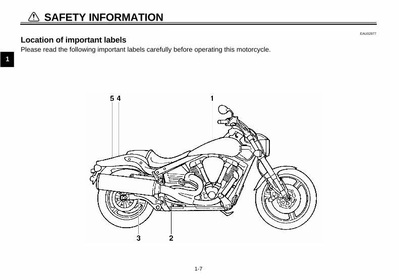
EAU02977
Location of important labels Please read the following important labels carefully before operating this motorcycle.

SAFETY INFORMATION
1
1-8
1
California only
2
3 4
5
California only


DESCRIPTION
2
Left view ............................................................................................. 2-1Right view........................................................................................... 2-2Controls and instruments ................................................................... 2-3

2-1
2
EAU00026
2-DESCRIPTION
Left view
1. Engine oil drain bolt (crankcase) (page 6-11)2. Shift pedal (page 3-7)3. Fuel tank cap (page 3-9)
4. Helmet holder (page 3-11)5. Fuses (page 6-37)6. Owner’s tool kit (page 6-2)

DESCRIPTION
2-2
2
Right view
7. Battery (page 6-35)8. Engine oil filler cap (page 6-9)9. Front fork spring preload adjusting bolt (page 3-12)
10. Engine oil filter cartridge (page 6-11)
11. Brake pedal (page 3-8)12. Engine oil drain bolt (oil tank) (page 6-10)13. Shock absorber assembly spring
preload adjusting nut (page 3-13)14. Shock absorber assembly rebound
damping force adjusting knob (page 3-14)

DESCRIPTION
2-3
2
Controls and instruments
1. Clutch lever (page 3-7)2. Left handlebar switches (page 3-6)3. Speedometer (page 3-3)4. Tachometer unit (page 3-4)5. Main switch/steering lock (page 3-1)
6. Right handlebar switches (page 3-7)7. Throttle grip (page 6-18)8. Brake lever (page 3-8)

INSTRUMENT AND CONTROL FUNCTIONS
3
Main switch/steering lock .................................................................. 3-1Indicator and warning lights ............................................................. 3-2Speedometer ..................................................................................... 3-3Tachometer unit ................................................................................. 3-4Handlebar switches ........................................................................... 3-6Clutch lever ....................................................................................... 3-7Shift pedal ......................................................................................... 3-7Brake lever ........................................................................................ 3-8Brake pedal ....................................................................................... 3-8Fuel tank cap ..................................................................................... 3-9Fuel ................................................................................................... 3-9Seat ................................................................................................. 3-11Helmet holder .................................................................................. 3-11Adjusting the front fork .................................................................... 3-12Adjusting the shock absorber assembly .......................................... 3-13Sidestand ........................................................................................ 3-15Ignition circuit cut-off system ........................................................... 3-16

3-1
3
EAU00027
3-INSTRUMENT AND CONTROL FUNCTIONS
EAU00029
Main switch/steering lock The main switch/steering lock controlsthe ignition and lighting systems, and isused to lock the steering. The variouspositions are described below.
EAU04437
ONAll electrical circuits are supplied withpower, and the meter lighting, taillight,license plate light and position lightscome on, and the engine can be start-ed. The key cannot be removed.
NOTE:_
The headlight comes on automaticallywhen the engine is started and stayson until the key is turned to “OFF”, evenif the engine stalls. _
EAU00038
OFFAll electrical systems are off. The keycan be removed.
EAU00040
LOCKThe steering is locked, and all electricalsystems are off. The key can be re-moved.
To lock the steering1. Turn the handlebars all the way to
the left.2. Push the key in from the “OFF” po-
sition, and then turn it to “LOCK”while still pushing it.
3. Remove the key.
To unlock the steeringPush the key in, and then turn it to“OFF” while still pushing it.

INSTRUMENT AND CONTROL FUNCTIONS
3-2
3
EW000016
WARNING_
Never turn the key to “OFF” or“LOCK” while the motorcycle ismoving, otherwise the electricalsystems will be switched off, whichmay result in loss of control or anaccident. Make sure that the motor-cycle is stopped before turning thekey to “OFF” or “LOCK”._
EAU03034
Indicator and warning lights
EAU00063
High beam indicator light “ ”This indicator light comes on when thehigh beam of the headlight is switchedon.
EAU04121
Turn signal indicator lights “ ”and “ ”The corresponding indicator light flash-es when the turn signal switch ispushed to the left or right.
EAU04878
Fuel level warning light “ ”This warning light comes on when thefuel level drops below approximately0.8 US gal (0.7 Imp gal, 3.0 L). Whenthis occurs, refuel as soon as possible.The electrical circuit of the warning lightcan be checked by turning the key to“ON”.If the warning light does not come onfor a few seconds, then go off, have aYamaha dealer check the electrical cir-cuit.
1. Push.2. Turn.
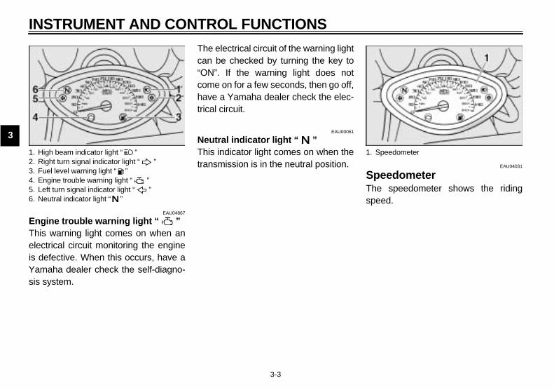
1. High beam indicator light “ ”2. Right turn signal indicator light “ ”3. Fuel level warning light “ ”4. Engine trouble warning light “ ”5. Left turn signal indicator light “ ”6. Neutral indicator light “ ”
INSTRUMENT AND CONTROL FUNCTIONS
3-3
3
EAU04867
Engine trouble warning light “ ”This warning light comes on when anelectrical circuit monitoring the engineis defective. When this occurs, have aYamaha dealer check the self-diagno-sis system.
The electrical circuit of the warning lightcan be checked by turning the key to“ON”. If the warning light does notcome on for a few seconds, then go off,have a Yamaha dealer check the elec-trical circuit.
EAU00061
Neutral indicator light “ ”This indicator light comes on when thetransmission is in the neutral position. EAU04031
SpeedometerThe speedometer shows the ridingspeed.
1. High beam indicator light “ ”2. Right turn signal indicator light “ ”3. Fuel level warning light “ ”4. Engine trouble warning light “ ”5. Left turn signal indicator light “ ”6. Neutral indicator light “ ”
1. Speedometer
INSTRUMENT AND CONTROL FUNCTIONS
3-4
3
EAU04436
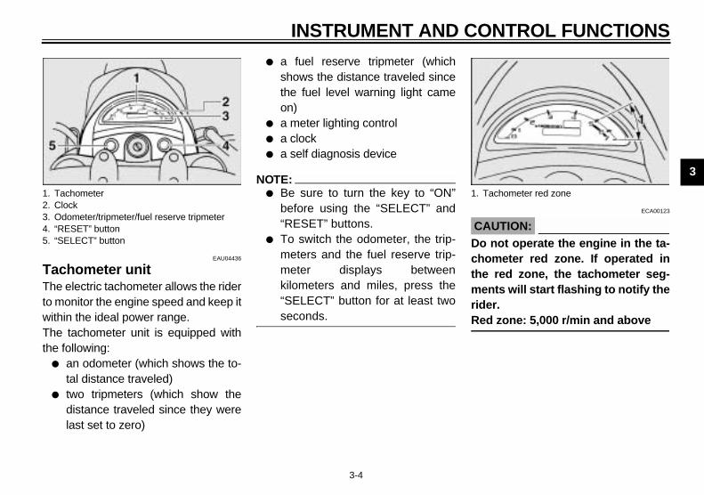
Tachometer unit The electric tachometer allows the riderto monitor the engine speed and keep itwithin the ideal power range.The tachometer unit is equipped withthe following:
● an odometer (which shows the to-tal distance traveled)
● two tripmeters (which show thedistance traveled since they werelast set to zero)
● a fuel reserve tripmeter (whichshows the distance traveled sincethe fuel level warning light cameon)
● a meter lighting control● a clock● a self diagnosis device
NOTE:_
● Be sure to turn the key to “ON”before using the “SELECT” and“RESET” buttons.
● To switch the odometer, the trip-meters and the fuel reserve trip-meter displays betweenkilometers and miles, press the“SELECT” button for at least twoseconds.
_
ECA00123
CAUTION:_
Do not operate the engine in the ta-chometer red zone. If operated inthe red zone, the tachometer seg-ments will start flashing to notify therider. Red zone: 5,000 r/min and above _
1. Tachometer2. Clock3. Odometer/tripmeter/fuel reserve tripmeter4. “RESET” button5. “SELECT” button
1. Tachometer red zone

INSTRUMENT AND CONTROL FUNCTIONS
3-5
3
Odometer and tripmeter modesPushing the “SELECT” button switchesthe display between the odometermode “ODO” and the tripmeter modes“TRIP 1” and “TRIP 2” in the followingorder:ODO → TRIP 1 → TRIP 2 → ODOIf the fuel level warning light comes on(see page 3-2), the odometer displaywill automatically change to the fuel re-serve tripmeter mode “TRIP F” andstart counting the distance traveledfrom that point. In that case, pushingthe “SELECT” button switches the dis-play between the various tripmeter andodometer modes in the following order:TRIP F → TRIP 1 → TRIP 2 → ODO →TRIP F
To reset a tripmeter, select it by push-ing the “SELECT” button, and thenpush the “RESET” button for at leastone second. If you do not reset the fuelreserve tripmeter manually, it will resetitself automatically and the display willreturn to the prior mode after refuelingand traveling 3 mi (5 km).
Meter lighting control mode1. Turn the key to “OFF”.2. Push and hold the “SELECT” but-
ton.3. Turn the key to “ON”, and then after
five seconds, release the “SELECT”button.
4. Push the “RESET” button to selectthe desired brightness.
5. Push the “SELECT” button to set thebrightness level.
6. Turn the key to “OFF”.
NOTE:_
When adjusting the meter lighting, theodometer display will indicate thebrightness level. _
Clock modeTo set the clock:
1. Push the “SELECT” button and“RESET” button together for atleast two seconds.
2. When the hour digits start flashing,push the “RESET” button to setthe hours.
3. Push the “SELECT” button, andthe minute digits will start flashing.
4. Push the “RESET” button to setthe minutes.
5. Push the “SELECT” button andthen release it to start the clock.
NOTE:_
● After setting the clock, be sure topush the “SELECT” button beforeturning the key to “OFF”, other-wise the clock will not be set.
● To set the clock after the batteryhas been disconnected, first setthe time to 1:00 AM, and then setthe clock to the correct time.
_

INSTRUMENT AND CONTROL FUNCTIONS
3-6
3
Self diagnosis deviceThis model is equipped with a self-di-agnosis device for various electrical cir-cuits.If any of those circuits are defective,the clock display will indicate a two-dig-it error code (e.g., 11, 12, 13).If the clock display indicates such anerror code, note the code number, andthen have a Yamaha dealer check themotorcycle.
ECA00122
CAUTION:_
If the clock display indicates an er-ror code, the motorcycle should bechecked as soon as possible in or-der to avoid engine damage. _
EAU00118
Handlebar switches
EAU03888
Dimmer switch “ / ”Set this switch to “ ” for the highbeam and to “ ” for the low beam.
EAU04218
Turn signal switch “ / ”To signal a right-hand turn, push thisswitch to “ ”. To signal a left-handturn, push this switch to “ ”. Whenreleased, the switch returns to the cen-ter position.Since this model is equipped with aself-canceling system, the turn signallights will self-cancel after the motor-cycle has traveled both about 490 ft(150 m) and for approximately 15 sec-onds. However, the turn signal lightscan also be canceled manually bypushing the switch in after it has re-turned to the center position.
NOTE:_
The self-canceling system only oper-ates when the motorcycle is moving, sothat the turn signal lights will not self-cancel while you are stopped at an in-tersection. _
EAU00129
Horn switch “ ”Press this switch to sound the horn.
1. Dimmer switch “ / ”2. Turn signal switch “ / ”3. Horn switch “ ”
INSTRUMENT AND CONTROL FUNCTIONS
3-7
3
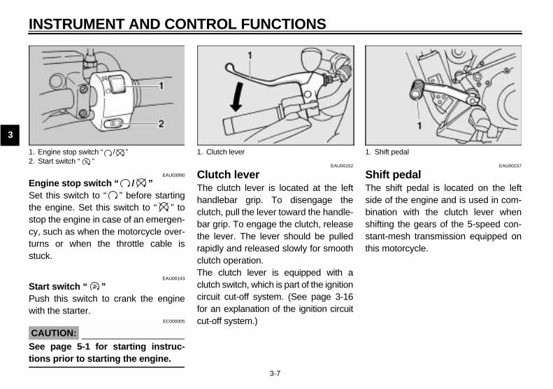
EAU03890
Engine stop switch “ / ”Set this switch to “ ” before startingthe engine. Set this switch to “ ” tostop the engine in case of an emergen-cy, such as when the motorcycle over-turns or when the throttle cable isstuck.
EAU00143
Start switch “ ”Push this switch to crank the enginewith the starter.
EC000005
CAUTION:_
See page 5-1 for starting instruc-tions prior to starting the engine. _
EAU00152
Clutch lever The clutch lever is located at the lefthandlebar grip. To disengage theclutch, pull the lever toward the handle-bar grip. To engage the clutch, releasethe lever. The lever should be pulledrapidly and released slowly for smoothclutch operation.The clutch lever is equipped with aclutch switch, which is part of the ignitioncircuit cut-off system. (See page 3-16for an explanation of the ignition circuitcut-off system.)
EAU00157
Shift pedal The shift pedal is located on the leftside of the engine and is used in com-bination with the clutch lever whenshifting the gears of the 5-speed con-stant-mesh transmission equipped onthis motorcycle.
1. Engine stop switch “ / ”2. Start switch “ ”
1. Clutch lever 1. Shift pedal

INSTRUMENT AND CONTROL FUNCTIONS
3-8
3
EAU00158
Brake lever The brake lever is located at the righthandlebar grip. To apply the frontbrake, pull the lever toward the handle-bar grip.
EAU00162
Brake pedal The brake pedal is on the right side ofthe motorcycle. To apply the rearbrake, press down on the brake pedal.
1. Brake lever 1. Brake pedal
INSTRUMENT AND CONTROL FUNCTIONS
3-9
3
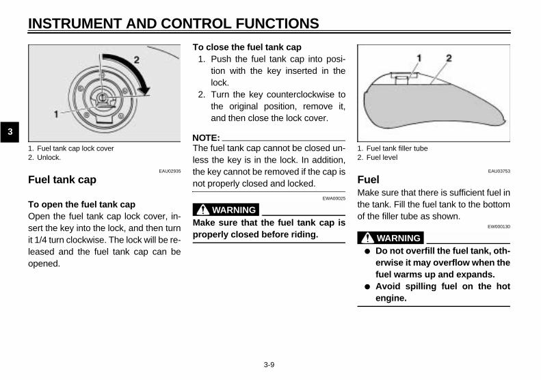
EAU02935
Fuel tank cap
To open the fuel tank capOpen the fuel tank cap lock cover, in-sert the key into the lock, and then turnit 1/4 turn clockwise. The lock will be re-leased and the fuel tank cap can beopened.
To close the fuel tank cap1. Push the fuel tank cap into posi-
tion with the key inserted in thelock.
2. Turn the key counterclockwise tothe original position, remove it,and then close the lock cover.
NOTE:_
The fuel tank cap cannot be closed un-less the key is in the lock. In addition,the key cannot be removed if the cap isnot properly closed and locked. _
EWA00025
WARNING_
Make sure that the fuel tank cap isproperly closed before riding. _
EAU03753
FuelMake sure that there is sufficient fuel inthe tank. Fill the fuel tank to the bottomof the filler tube as shown.
EW000130
WARNING_
● Do not overfill the fuel tank, oth-erwise it may overflow when thefuel warms up and expands.
● Avoid spilling fuel on the hotengine.
_
1. Fuel tank cap lock cover2. Unlock.
1. Fuel tank filler tube2. Fuel level

INSTRUMENT AND CONTROL FUNCTIONS
3-10
3
EAU00185
CAUTION:_
Immediately wipe off spilled fuelwith a clean, dry, soft cloth, sincefuel may deteriorate painted surfac-es or plastic parts. _
EAU04438
ECA00104
CAUTION:_
Use only unleaded gasoline. Theuse of leaded gasoline will cause se-vere damage to internal engineparts, such as the valves and pistonrings, as well as to the exhaust sys-tem._
Your Yamaha engine has been de-signed to use regular unleaded gaso-line with a pump octane number[(R+M)/2] of 86 or higher, or a researchoctane number of 91 or higher. Ifknocking (or pinging) occurs, use agasoline of a different brand or premi-um unleaded fuel. Use of unleaded fuelwill extend spark plug life and reducemaintenance costs.
GasoholThere are two types of gasohol: gaso-hol containing ethanol and that contain-ing methanol. Gasohol containingethanol can be used if the ethanol con-tent does not exceed 10%. Gasoholcontaining methanol is not recom-mended by Yamaha because it cancause damage to the fuel system or ve-hicle performance problems.
Recommended fuel:UNLEADED GASOLINE ONLY
Fuel tank capacity:Total amount:
4.0 US gal (3.3 Imp gal, 15.0 L)Amount remaining when the fuel level warning light comes on:
0.8 US gal (0.7 Imp gal, 3.0 L)
INSTRUMENT AND CONTROL FUNCTIONS
3-11
3
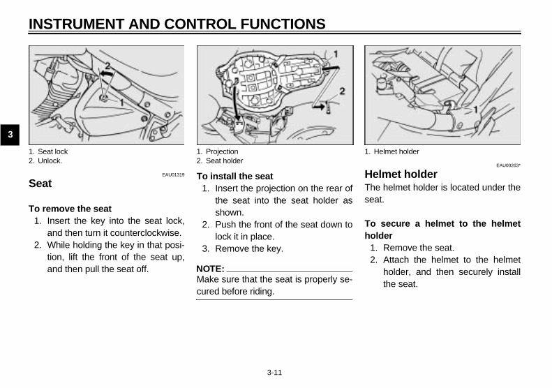
EAU01319
Seat
To remove the seat1. Insert the key into the seat lock,
and then turn it counterclockwise.2. While holding the key in that posi-
tion, lift the front of the seat up,and then pull the seat off.
To install the seat1. Insert the projection on the rear of
the seat into the seat holder asshown.
2. Push the front of the seat down tolock it in place.
3. Remove the key.
NOTE:_
Make sure that the seat is properly se-cured before riding. _
EAU00263*
Helmet holder The helmet holder is located under theseat.
To secure a helmet to the helmetholder
1. Remove the seat.2. Attach the helmet to the helmet
holder, and then securely installthe seat.
1. Seat lock2. Unlock.
1. Projection2. Seat holder
1. Helmet holder

INSTRUMENT AND CONTROL FUNCTIONS
3-12
3
EW000030
WARNING_
Never ride with a helmet attached tothe helmet holder, since the helmetmay hit objects, causing loss ofcontrol and possibly an accident. _
To release the helmet from thehelmet holderRemove the seat, remove the helmetfrom the helmet holder, and then installthe seat.
EAU00285
Adjusting the front fork This front fork is equipped with springpreload adjusting bolts.
EW000035
WARNING_
Always adjust both fork legs equal-ly, otherwise poor handling and lossof stability may result. _
Adjust the spring preload as follows.To increase the spring preload andthereby harden the suspension, turnthe adjusting bolt on each fork leg in di-rection a. To decrease the spring pre-load and thereby soften thesuspension, turn the adjusting bolt oneach fork leg in direction b.
NOTE:_
Align the appropriate groove on the ad-justing mechanism with the top of thefront fork cap bolt. _
CI-10E
1. Spring preload adjusting bolt 1. Current setting2. Front fork cap bolt
Setting
Minimum (soft) 8
Standard 5
Maximum (hard) 1
INSTRUMENT AND CONTROL FUNCTIONS
3-13
3
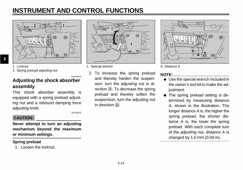
EAU04873
Adjusting the shock absorber assemblyThis shock absorber assembly isequipped with a spring preload adjust-ing nut and a rebound damping forceadjusting knob.
EC000015
CAUTION:_
Never attempt to turn an adjustingmechanism beyond the maximumor minimum settings. _
Spring preload1. Loosen the locknut.
2. To increase the spring preloadand thereby harden the suspen-sion, turn the adjusting nut in di-rection a. To decrease the springpreload and thereby soften thesuspension, turn the adjusting nutin direction b.
NOTE:_
● Use the special wrench included inthe owner’s tool kit to make the ad-justment.
● The spring preload setting is de-termined by measuring distanceA, shown in the illustration. Thelonger distance A is, the higher thespring preload; the shorter dis-tance A is, the lower the springpreload. With each complete turnof the adjusting nut, distance A ischanged by 1.0 mm (0.04 in).
_
1. Locknut2. Spring preload adjusting nut
1. Special wrench A. Distance A

INSTRUMENT AND CONTROL FUNCTIONS
3-14
33. Tighten the locknut to the speci-
fied torque.
ECA00076
CAUTION:_
Always tighten the locknut againstthe adjusting nut, and then tightenthe locknut to the specified torque. _
Rebound damping forceTo increase the rebound dampingforce and thereby harden the rebounddamping, turn the adjusting knob in di-rection a. To decrease the rebounddamping force and thereby soften therebound damping, turn the adjustingknob in direction b.CI-08E
NOTE:_
Although the total number of clicks ofthe damping force adjusting mecha-nism may not exactly match the abovespecifications due to small differencesin production, the actual number ofclicks always represents the entire ad-justing range. To obtain a precise ad-justment, it would be advisable tocheck the number of clicks of thedamping force adjusting mechanismand to modify the specifications as nec-essary._
Spring preload:Minimum (soft):
Distance A = 2.05 in (52 mm)Standard:
Distance A = 2.13 in (54 mm)Maximum (hard):
Distance A = 2.48 in (63 mm)
Tightening torque:Locknut:
36 ft·lbf (5.0 m·kgf, 50 Nm)
1. Rebound damping force adjusting knob
Minimum (soft) 20 clicks in direction b*
Standard 10 clicks in direction b*
Maximum (hard) 3 clicks in direction b*
* With the adjusting knob fully turned in direction a
INSTRUMENT AND CONTROL FUNCTIONS
3-15
3
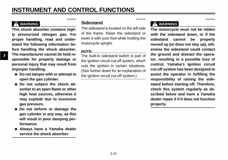
EAU00315
WARNING_
This shock absorber contains high-ly pressurized nitrogen gas. Forproper handling, read and under-stand the following information be-fore handling the shock absorber.The manufacturer cannot be held re-sponsible for property damage orpersonal injury that may result fromimproper handling.
● Do not tamper with or attempt toopen the gas cylinder.
● Do not subject the shock ab-sorber to an open flame or otherhigh heat sources, otherwise itmay explode due to excessivegas pressure.
● Do not deform or damage thegas cylinder in any way, as thiswill result in poor damping per-formance.
● Always have a Yamaha dealerservice the shock absorber.
_
EAU00330
SidestandThe sidestand is located on the left sideof the frame. Raise the sidestand orlower it with your foot while holding themotorcycle upright.
NOTE:_
The built-in sidestand switch is part ofthe ignition circuit cut-off system, whichcuts the ignition in certain situations.(See further down for an explanation ofthe ignition circuit cut-off system.) _
EW000044
WARNING_
The motorcycle must not be riddenwith the sidestand down, or if thesidestand cannot be properlymoved up (or does not stay up), oth-erwise the sidestand could contactthe ground and distract the opera-tor, resulting in a possible loss ofcontrol. Yamaha’s ignition circuitcut-off system has been designed toassist the operator in fulfilling theresponsibility of raising the side-stand before starting off. Therefore,check this system regularly as de-scribed below and have a Yamahadealer repair it if it does not functionproperly. _
INSTRUMENT AND CONTROL FUNCTIONS
3-16
3
EAU03720
Ignition circuit cut-off system The ignition circuit cut-off system (com-prising the sidestand switch, clutchswitch and neutral switch) has the fol-lowing functions.
● It prevents starting when the trans-mission is in gear and the side-stand is up, but the clutch lever isnot pulled.
● It prevents starting when the trans-mission is in gear and the clutchlever is pulled, but the sidestand isstill down.
● It cuts the running engine whenthe transmission is in gear and thesidestand is moved down.
Periodically check the operation of theignition circuit cut-off system accordingto the following procedure.
EW000045
WARNING_
If a malfunction is noted, have aYamaha dealer check the systembefore riding. _
INSTRUMENT AND CONTROL FUNCTIONS
3-17
3
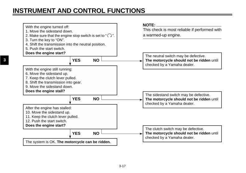
CD-01E
With the engine turned off:1. Move the sidestand down.2. Make sure that the engine stop switch is set to “ ”.3. Turn the key to “ON”.4. Shift the transmission into the neutral position.5. Push the start switch.Does the engine start?
The neutral switch may be defective.The motorcycle should not be ridden until checked by a Yamaha dealer.
With the engine still running:6. Move the sidestand up.7. Keep the clutch lever pulled.8. Shift the transmission into gear.9. Move the sidestand down.Does the engine stall?
After the engine has stalled:10. Move the sidestand up.11. Keep the clutch lever pulled.12. Push the start switch.Does the engine start?
The sidestand switch may be defective.The motorcycle should not be ridden until checked by a Yamaha dealer.
The clutch switch may be defective.The motorcycle should not be ridden until checked by a Yamaha dealer.
NO
NOTE:This check is most reliable if performed witha warmed-up engine.
YES
YES NO
The system is OK. The motorcycle can be ridden.
YES NO

PRE-OPERATION CHECKS
4
Pre-operation check list ..................................................................... 4-1

4-1
4
EAU01114
4-PRE-OPERATION CHECKS
The condition of a vehicle is the owner’s responsibility. Vital components can start to deteriorate quickly and unexpectedly,even if the vehicle remains unused (for example, as a result of exposure to the elements). Any damage, fluid leakage or lossof tire air pressure could have serious consequences. Therefore, it is very important, in addition to a thorough visual inspec-tion, to check the following points before each ride.
EAU03439
Pre-operation check list CO-01E
ITEM CHECKS PAGE
Fuel• Check fuel level in fuel tank.• Refuel if necessary.• Check fuel line for leakage.
3-9–3-10
Engine oil• Check oil level in engine.• If necessary, add recommended oil to specified level.• Check vehicle for oil leakage.
6-9–6-10
Front brake
• Check operation.• If soft or spongy, have Yamaha dealer bleed hydraulic system.• Check lever free play.• Adjust if necessary.• Check fluid level in reservoir.• If necessary, add recommended brake fluid to specified level.• Check hydraulic system for leakage.
6-24, 6-26–6-28
Rear brake
• Check operation.• If soft or spongy, have Yamaha dealer bleed hydraulic system.• Check fluid level in reservoir.• If necessary, add recommended brake fluid to specified level.• Check hydraulic system for leakage.
6-25–6-28
Clutch
• Check operation.• Lubricate cable if necessary.• Check lever free play.• Adjust if necessary.
6-23–6-24
Throttle grip
• Make sure that operation is smooth.• Check cable free play.• If necessary, have Yamaha dealer adjust cable free play and lubricate cable and
grip housing.
6-18, 6-31

PRE-OPERATION CHECKS
4-2
4
NOTE:_
Pre-operation checks should be made each time the motorcycle is used. Such an inspection can be accomplished in a veryshort time; and the added safety it assures is more than worth the time involved. _
EWA00033
WARNING_
If any item in the Pre-operation check list is not working properly, have it inspected and repaired before operatingthe motorcycle. _
Control cables • Make sure that operation is smooth.• Lubricate if necessary. 6-31
Wheels and tires
• Check for damage.• Check tire condition and tread depth.• Check air pressure.• Correct if necessary.
6-19–6-22
Brake and shift pedals • Make sure that operation is smooth.• Lubricate pedal pivoting points if necessary. 6-31
Brake and clutch levers • Make sure that operation is smooth.• Lubricate lever pivoting points if necessary. 6-32
Sidestand • Make sure that operation is smooth.• Lubricate pivot if necessary. 6-33
Chassis fasteners • Make sure that all nuts, bolts and screws are properly tightened.• Tighten if necessary. —
Instruments, lights, signals and switches
• Check operation. • Correct if necessary. —
Sidestand switch • Check operation of ignition circuit cut-off system.• If system is defective, have Yamaha dealer check vehicle. 3-15
ITEM CHECKS PAGE


OPERATION AND IMPORTANT RIDING POINTS
5
Starting and warming up a cold engine ............................................. 5-1Shifting .............................................................................................. 5-3Engine break-in ................................................................................. 5-5Parking .............................................................................................. 5-5

5-1
5
EAU00372
5-OPERATION AND IMPORTANT RIDING POINTS
EAU00373
WARNING_
● Become thoroughly familiarwith all operating controls andtheir functions before riding.Consult a Yamaha dealer re-garding any control or functionthat you do not thoroughly un-derstand.
● Never start the engine or operateit in a closed area for any lengthof time. Exhaust fumes are poi-sonous, and inhaling them cancause loss of consciousnessand death within a short time. Al-ways make sure that there is ad-equate ventilation.
● Before starting out, make surethat the sidestand is up. If thesidestand is not raised com-pletely, it could contact theground and distract the opera-tor, resulting in a possible lossof control.
_
EAU00376
CAUTION:_
● Make sure not to store personalitems near the air cleaner in-take, otherwise air intake will beblocked and performance willsuffer.
● Make sure not to put anythingnear the battery and its termi-nals, otherwise electrical failureand acid corrosion may result.
_
EAU04440
Starting and warming up a cold engine In order for the ignition circuit cut-offsystem to enable starting, one of thefollowing conditions must be met:
● The transmission is in the neutralposition.
● The transmission is in gear withthe clutch lever pulled and thesidestand up.
EW000054
WARNING_
● Before starting the engine,check the function of the igni-tion circuit cut-off system ac-cording to the proceduredescribed on page 3-17.
● Never ride with the sidestanddown.
_
1. Turn the key to “ON” and makesure that the engine stop switch isset to “ ”.
OPERATION AND IMPORTANT RIDING POINTS
5-2
5
ECA00124
CAUTION:_
The fuel level warning light and en-gine trouble warning light shouldcome on for a few seconds, then gooff. If a warning light does not go off,see pages 3-2 and 3-3 for the corre-sponding warning light circuitcheck._
2. Shift the transmission into the neu-tral position.
NOTE:_
When the transmission is in the neutralposition, the neutral indicator lightshould be on, otherwise have aYamaha dealer check the electrical cir-cuit. _
3. Start the engine by pushing thestart switch.
NOTE:_
If the engine fails to start, release thestart switch, wait a few seconds, andthen try again. Each starting attemptshould be as short as possible to pre-serve the battery. Do not crank the en-gine more than 10 seconds on any oneattempt. _
ECA00055
CAUTION:_
For maximum engine life, alwayswarm the engine up before startingoff. Never accelerate hard when theengine is cold! _
NOTE:_
The engine is warm when it quickly re-sponds to the throttle. _

OPERATION AND IMPORTANT RIDING POINTS
5-3
5
EAU00423
ShiftingShifting gears lets you control theamount of engine power available forstarting off, accelerating, climbing hills,etc.The gear positions are shown in the il-lustration.
NOTE:_
To shift the transmission into the neu-tral position, press the shift pedal downrepeatedly until it reaches the end of itstravel, and then slightly raise it. _
EC000048
CAUTION:_
● Even with the transmission inthe neutral position, do notcoast for long periods of timewith the engine off, and do nottow the motorcycle for long dis-tances. The transmission isproperly lubricated only whenthe engine is running. Inade-quate lubrication may damagethe transmission.
● Always use the clutch whilechanging gears to avoid dam-aging the engine, transmission,and drive train, which are notdesigned to withstand theshock of forced shifting.
_
EAU02988
To start out and accelerate 1. Pull the clutch lever to disengage
the clutch.2. Shift the transmission into first
gear. The neutral indicator lightshould go out.
3. Open the throttle gradually, and atthe same time, release the clutchlever slowly.
4. At the recommended shift pointsshown in the table on page 5-4,close the throttle, and at the sametime, quickly pull the clutch leverin.
5. Shift the transmission into secondgear. (Make sure not to shift thetransmission into the neutral posi-tion.)
6. Open the throttle part way andgradually release the clutch lever.
7. Follow the same procedure whenshifting to the next higher gear.
NOTE:_
Always shift gears at the recommend-ed shift points. _
1. Shift pedalN. Neutral position
OPERATION AND IMPORTANT RIDING POINTS
5-4
5
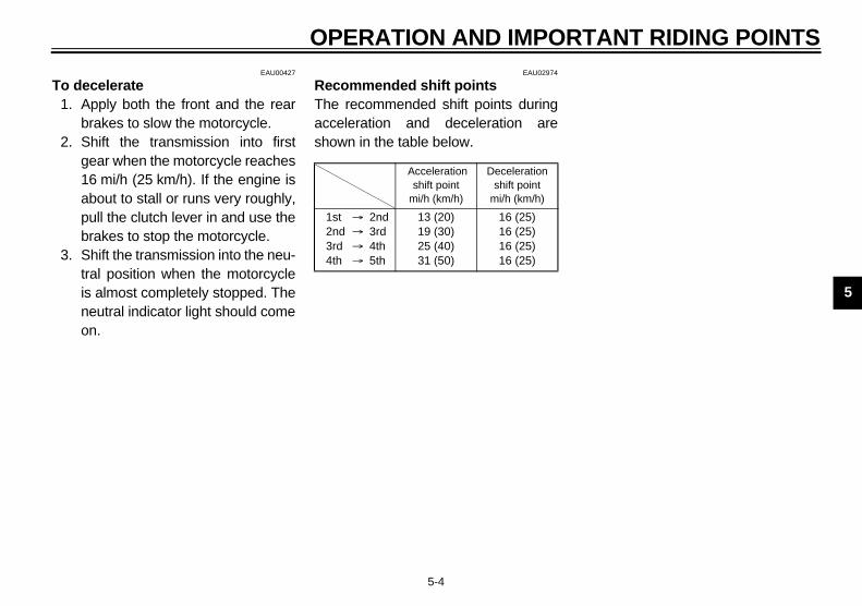
EAU00427
To decelerate 1. Apply both the front and the rear
brakes to slow the motorcycle.2. Shift the transmission into first
gear when the motorcycle reaches16 mi/h (25 km/h). If the engine isabout to stall or runs very roughly,pull the clutch lever in and use thebrakes to stop the motorcycle.
3. Shift the transmission into the neu-tral position when the motorcycleis almost completely stopped. Theneutral indicator light should comeon.
EAU02974
Recommended shift points The recommended shift points duringacceleration and deceleration areshown in the table below.CF-04E
Acceleration shift point
mi/h (km/h)
Deceleration shift point
mi/h (km/h)
1st → 2nd2nd → 3rd3rd → 4th4th → 5th
13 (20)19 (30)25 (40)31 (50)
16 (25)16 (25)16 (25)16 (25)
OPERATION AND IMPORTANT RIDING POINTS
5-5
5
EAU01128
Engine break-in There is never a more important periodin the life of your engine than the periodbetween 0 and 1,000 mi (1,600 km).For this reason, you should read thefollowing material carefully.Since the engine is brand new, do notput an excessive load on it for the first1,000 mi (1,600 km). The various partsin the engine wear and polish them-selves to the correct operating clear-ances. During this period, prolongedfull-throttle operation or any conditionthat might result in engine overheatingmust be avoided.
EAU04441*
0–600 mi (0–1,000 km)Avoid prolonged operation above2,500 r/min.
600–1,000 mi (1,000–1,600 km)Avoid prolonged operation above3,500 r/min.
ECA00026*
CAUTION:_
After 600 mi (1,000 km) of operation,the engine oil and transfer case oilmust be changed, and the oil filtercartridge replaced. _
1,000 mi (1,600 km) and beyondThe vehicle can now be operated nor-mally.
EC000053
CAUTION:_
● Keep the engine speed out ofthe tachometer red zone.
● If any engine trouble should oc-cur during the engine break-inperiod, immediately have aYamaha dealer check the vehi-cle.
_
EAU00461
Parking When parking, stop the engine, andthen remove the key from the mainswitch.
EW000058
WARNING_
● Since the engine and exhaustsystem can become very hot,park in a place where pedestri-ans or children are not likely totouch them.
● Do not park on a slope or onsoft ground, otherwise themotorcycle may overturn.
_
EC000062
CAUTION:_
Never park in an area where thereare fire hazards such as grass orother flammable materials. _

6
PERIODIC MAINTENANCE AND MINOR REPAIR
Periodic maintenance ..........................................6-1Owner’s tool kit ....................................................6-2Periodic maintenance chart for the emission
control system ...................................................6-3General maintenance and lubrication chart .........6-4Checking the spark plugs ....................................6-7Canister (for California only) ................................6-8Engine oil and oil filter cartridge ..........................6-9Transfer case oil .................................................6-13Replacing the air filter elements ........................6-13Adjusting the throttle cable free play ..................6-18Adjusting the valve clearance ............................6-19Tires ...................................................................6-19Cast wheels .......................................................6-22Accessories and replacement parts ..................6-23Adjusting the clutch lever free play ....................6-23Adjusting the brake lever free play .....................6-24Adjusting the brake pedal position .....................6-25Adjusting the rear brake light switch ..................6-25Checking the front and rear brake pads .............6-26Checking the brake fluid level ............................6-27Changing the brake fluid ....................................6-28
Drive belt slack .................................................. 6-29Checking and lubricating the cables ................. 6-31Checking and lubricating the throttle grip and
cable ............................................................... 6-31Checking and lubricating the brake and
shift pedals ...................................................... 6-31Checking and lubricating the brake and
clutch levers .................................................... 6-32Checking and lubricating the sidestand ............ 6-33Lubricating the rear suspension ........................ 6-33Checking the front fork ...................................... 6-33Checking the steering ....................................... 6-34Checking the wheel bearings ............................ 6-35Battery ............................................................... 6-35Replacing the fuses .......................................... 6-37Replacing the headlight bulb ............................. 6-38Tail/brake light ................................................... 6-40Replacing a turn signal light bulb ...................... 6-40Replacing a license plate light bulb ................... 6-41Supporting the motorcycle ................................ 6-42Troubleshooting ................................................. 6-42Troubleshooting chart ........................................ 6-43

6-1
6
EAU00462
6-PERIODIC MAINTENANCE AND MINOR REPAIR EAU01790
Safety is an obligation of the owner.Periodic inspection, adjustment and lu-brication will keep your vehicle in thesafest and most efficient condition pos-sible. The most important points ofmotorcycle inspection, adjustment, andlubrication are explained on the follow-ing pages.Maintenance, replacement, or repairof the emission control devices andsystems may be performed by anyrepair establishment or individualthat is certified (if applicable).
EW000060
WARNING_
If you are not familiar with motor-cycle maintenance work, have aYamaha dealer do it for you. _
EAU00467
PERIODIC MAINTENANCE PROPER PERIODIC MAINTENANCEOF YOUR MOTORCYCLE IS IMPOR-TANT IN ORDER TO ENJOY LONG,PLEASURABLE SERVICE. ESPE-CIALLY IMPORTANT ARE THEMAINTENANCE SERVICES RELAT-ED TO EMISSIONS CONTROL.THESE CONTROLS NOT ONLYFUNCTION TO ENSURE CLEANERAIR, BUT ARE ALSO VITAL TOPROPER ENGINE OPERATION ANDMAXIMUM PERFORMANCE. IN THEFOLLOWING PERIODIC MAINTE-NANCE CHARTS, THE SERVICESRELATED TO EMISSIONS CON-
TROL ARE GROUPED SEPARATE-LY. THESE SERVICES REQUIRESPECIALIZED DATA, KNOWLEDGE,AND EQUIPMENT. YAMAHA DEAL-ERS ARE TRAINED AND EQUIPPEDTO PERFORM THESE PARTICULARSERVICES.

PERIODIC MAINTENANCE AND MINOR REPAIR
6-2
6
EAU03983
Owner’s tool kit The owner’s tool kit is located underthe seat. (See page 3-11 for seat re-moval and installation procedures.)The service information included in thismanual and the tools provided in theowner’s tool kit are intended to assistyou in the performance of preventivemaintenance and minor repairs. How-ever, additional tools such as a torquewrench may be necessary to performcertain maintenance work correctly.
NOTE:_
If you do not have the tools or experi-ence required for a particular job, havea Yamaha dealer perform it for you. _
EW000062
WARNING_
Modifications not approved byYamaha may cause loss of perfor-mance, excessive emissions, andrender the vehicle unsafe for use.Consult a Yamaha dealer before at-tempting any changes. _
1. Owner’s tool kit
PERIODIC MAINTENANCE AND MINOR REPAIR
6-3
6
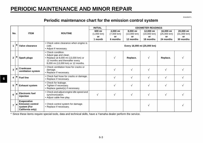
EAU00471
Periodic maintenance chart for the emission control system
No. ITEM ROUTINE
INITIAL ODOMETER READINGS600 mi
(1,000 km) or
1 month
4,000 mi(7,000 km)
or6 months
8,000 mi(13,000 km)
or12 months
12,000 mi(19,000 km)
or18 months
16,000 mi(25,000 km)
or24 months
20,000 mi(31,000 km)
or30 months
1 * Valve clearance• Check valve clearance when engine is
cold.• Adjust if necessary.
Every 16,000 mi (25,000 km)
2 * Spark plugs
• Check condition. • Adjust gap and clean. • Replace at 8,000 mi (13,000 km) or
12 months and thereafter every 8,000 mi (13,000 km) or 12 months.
√ Replace. √ Replace. √
3 * Crankcase ventilation system
• Check ventilation hose for cracks or damage.
• Replace if necessary.√ √ √ √ √
4 * Fuel line • Check fuel hose for cracks or damage.• Replace if necessary. √ √ √ √ √
5 * Exhaust system• Check for leakage. • Tighten if necessary. • Replace gasket(s) if necessary.
√ √ √ √ √
6 * Electronic fuel injection
• Check and adjust engine idle speed and synchronization.
• Adjust cable free play.√ √ √ √ √ √
7 *Evaporative Emission control system (For California only)
• Check control system for damage.• Replace if necessary. √ √
* Since these items require special tools, data and technical skills, have a Yamaha dealer perform the service.

PERIODIC MAINTENANCE AND MINOR REPAIR
6-4
6
EAU00472
General maintenance and lubrication chart
No. ITEM ROUTINE TYPE
INITIAL ODOMETER READINGS600 mi
(1,000 km)or
1 month
4,000 mi(7,000 km)
or6 months
8,000 mi(13,000 km)
or12 months
12,000 mi(19,000 km)
or18 months
16,000 mi(25,000 km)
or24 months
20,000 mi(31,000 km)
or30 months
1 Engine oil • Change. See page 8-1. √ √ √ √ √ √
2 * Engine oil filter cartridge • Replace. - √ √ √
3 * Air filter elements
• Check condition and for damage. (See NOTE on page 6-6.)
• Replace if necessary.
- √ √ √ √ √
4 * Front brake
• Check operation and fluid leakage. (See NOTE page 6-6.)
• Correct if necessary.
- √ √ √ √ Replace brake fluid. √
5 * Rear brake
• Check operation and fluid leakage. (See NOTE page 6-6.)
• Correct if necessary.
- √ √ √ √ Replace brake fluid. √
6 * Clutch• Check operation and free
play.• Correct if necessary.
- √ √ √ √ √ √
7 * Transfer case oil• Check vehicle for leakage.• Replace every 16,000 mi
(25,000 km) or 24 months.
SAE 80 API “GL-4”hypoid gear oil
Change. Check. Change.
8 *Throttle grip housing and cable
• Check operation and free play.
• Adjust the throttle cable free play if necessary.
• Lubricate the throttle grip housing and cable.
- √ √ √ √ √
* Since these items require special tools, data and technical skills, have a Yamaha dealer perform the service.
PERIODIC MAINTENANCE AND MINOR REPAIR
6-5
6
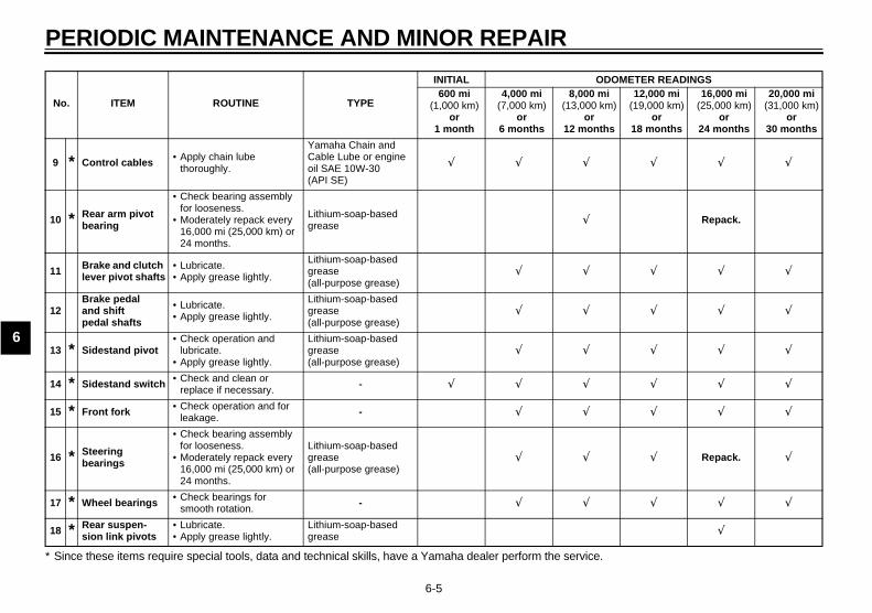
9 * Control cables • Apply chain lube thoroughly.
Yamaha Chain and Cable Lube or engine oil SAE 10W-30 (API SE)
√ √ √ √ √ √
10 * Rear arm pivot bearing
• Check bearing assembly for looseness.
• Moderately repack every 16,000 mi (25,000 km) or 24 months.
Lithium-soap-based grease √ Repack.
11 Brake and clutch lever pivot shafts
• Lubricate.• Apply grease lightly.
Lithium-soap-based grease(all-purpose grease)
√ √ √ √ √
12Brake pedal and shift pedal shafts
• Lubricate.• Apply grease lightly.
Lithium-soap-based grease(all-purpose grease)
√ √ √ √ √
13 * Sidestand pivot• Check operation and
lubricate.• Apply grease lightly.
Lithium-soap-based grease(all-purpose grease)
√ √ √ √ √
14 * Sidestand switch • Check and clean or replace if necessary. - √ √ √ √ √ √
15 * Front fork • Check operation and for leakage.
- √ √ √ √ √
16 * Steering bearings
• Check bearing assembly for looseness.
• Moderately repack every 16,000 mi (25,000 km) or 24 months.
Lithium-soap-based grease(all-purpose grease)
√ √ √ Repack. √
17 * Wheel bearings • Check bearings for smooth rotation. - √ √ √ √ √
18 * Rear suspen-sion link pivots
• Lubricate.• Apply grease lightly.
Lithium-soap-based grease √
No. ITEM ROUTINE TYPE
INITIAL ODOMETER READINGS600 mi
(1,000 km)or
1 month
4,000 mi(7,000 km)
or6 months
8,000 mi(13,000 km)
or12 months
12,000 mi(19,000 km)
or18 months
16,000 mi(25,000 km)
or24 months
20,000 mi(31,000 km)
or30 months
* Since these items require special tools, data and technical skills, have a Yamaha dealer perform the service.
PERIODIC MAINTENANCE AND MINOR REPAIR
6-6
6
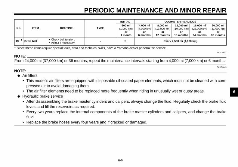
EAU03907
NOTE:_
From 24,000 mi (37,000 km) or 36 months, repeat the maintenance intervals starting from 4,000 mi (7,000 km) or 6 months. _
EAU04443
NOTE:_
● Air filters• This model’s air filters are equipped with disposable oil-coated paper elements, which must not be cleaned with com-
pressed air to avoid damaging them.• The air filter elements need to be replaced more frequently when riding in unusually wet or dusty areas.
● Hydraulic brake service• After disassembling the brake master cylinders and calipers, always change the fluid. Regularly check the brake fluid
levels and fill the reservoirs as required.• Every two years replace the internal components of the brake master cylinders and calipers, and change the brake
fluid.• Replace the brake hoses every four years and if cracked or damaged.
_
19 * Drive belt • Check belt tension.• Adjust if necessary. - √ Every 2,500 mi (4,000 km)
No. ITEM ROUTINE TYPE
INITIAL ODOMETER READINGS600 mi
(1,000 km)or
1 month
4,000 mi(7,000 km)
or6 months
8,000 mi(13,000 km)
or12 months
12,000 mi(19,000 km)
or18 months
16,000 mi(25,000 km)
or24 months
20,000 mi(31,000 km)
or30 months
* Since these items require special tools, data and technical skills, have a Yamaha dealer perform the service.
PERIODIC MAINTENANCE AND MINOR REPAIR
6-7
6
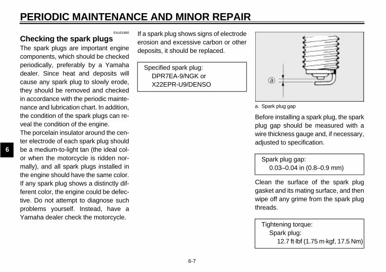
EAU01880
Checking the spark plugs The spark plugs are important enginecomponents, which should be checkedperiodically, preferably by a Yamahadealer. Since heat and deposits willcause any spark plug to slowly erode,they should be removed and checkedin accordance with the periodic mainte-nance and lubrication chart. In addition,the condition of the spark plugs can re-veal the condition of the engine.The porcelain insulator around the cen-ter electrode of each spark plug shouldbe a medium-to-light tan (the ideal col-or when the motorcycle is ridden nor-mally), and all spark plugs installed inthe engine should have the same color.If any spark plug shows a distinctly dif-ferent color, the engine could be defec-tive. Do not attempt to diagnose suchproblems yourself. Instead, have aYamaha dealer check the motorcycle.
If a spark plug shows signs of electrodeerosion and excessive carbon or otherdeposits, it should be replaced.
Before installing a spark plug, the sparkplug gap should be measured with awire thickness gauge and, if necessary,adjusted to specification.
Clean the surface of the spark pluggasket and its mating surface, and thenwipe off any grime from the spark plugthreads.
Specified spark plug:DPR7EA-9/NGK orX22EPR-U9/DENSO
a. Spark plug gap
Spark plug gap:0.03–0.04 in (0.8–0.9 mm)
Tightening torque:Spark plug:
12.7 ft·lbf (1.75 m·kgf, 17.5 Nm)

PERIODIC MAINTENANCE AND MINOR REPAIR
6-8
6
NOTE:_
If a torque wrench is not available wheninstalling a spark plug, a good estimateof the correct torque is 1/4–1/2 turnpast finger tight. However, the sparkplug should be tightened to the speci-fied torque as soon as possible. _
EAU00499
Canister (for California only) This model is equipped with a canisterto prevent the discharging of fuel vaporinto the atmosphere. Before operatingthis motorcycle, make sure to checkthe following:
● Check each hose connection.● Check each hose and canister for
cracks or damage. Replace ifdamaged.
● Make sure that the canisterbreather is not blocked, and if nec-essary, clean it.

PERIODIC MAINTENANCE AND MINOR REPAIR
6-9
6
EAU04909
Engine oil and oil filter cartridgeThe engine oil level should be checkedbefore each ride. In addition, the oilmust be changed and the oil filter car-tridge replaced at the intervals speci-fied in the periodic maintenance andlubrication chart.
To check the engine oil level1. Place the motorcycle on a level
surface and hold it in an uprightposition.
NOTE:_
Make sure that the motorcycle is posi-tioned straight up when checking the oillevel. A slight tilt to the side can result ina false reading. _
2. Remove the seat. (See page 3-11for seat removal and installationprocedures.)
3. Start the engine, warm it up untilthe engine oil has reached a nor-mal temperature of 140 °F (60 °C),let it continue to idle for ten sec-onds, and then turn the engine off.
NOTE:_
To achieve the proper engine oil tem-perature for an accurate oil level read-ing, the engine must have firstcompletely cooled down, and thenwarmed up again for several minutes tonormal operating temperature. _
4. Wait a few minutes until the oil set-tles, remove the oil filler cap, wipethe dipstick clean, insert it backinto the oil filler hole (withoutscrewing it in), and then remove itagain to check the oil level.
NOTE:_
The engine oil should be between theminimum and maximum level marks. _
5. If the engine oil is below the mini-mum level mark, add sufficient oilof the recommended type to raiseit to the correct level.
1. Engine oil filler cap 1. Maximum level mark2. Minimum level mark3. Dipstick
PERIODIC MAINTENANCE AND MINOR REPAIR
6-10
6
NOTE:_
When adding oil, be careful not to over-fill the engine oil tank; the oil level risesfaster starting from the half level por-tion on the dipstick. _
6. Insert the dipstick into the oil fillerhole, and then tighten the oil fillercap.
7. Install the seat.ECA00027
CAUTION:_
Make sure that the oil filler cap is se-curely tightened, otherwise oil mayseep out when the engine is run-ning._
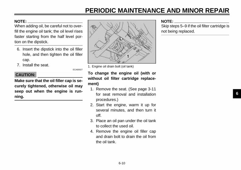
To change the engine oil (with orwithout oil filter cartridge replace-ment)
1. Remove the seat. (See page 3-11for seat removal and installationprocedures.)
2. Start the engine, warm it up forseveral minutes, and then turn itoff.
3. Place an oil pan under the oil tankto collect the used oil.
4. Remove the engine oil filler capand drain bolt to drain the oil fromthe oil tank.
NOTE:_
Skip steps 5–9 if the oil filter cartridge isnot being replaced. _
1. Engine oil drain bolt (oil tank)

PERIODIC MAINTENANCE AND MINOR REPAIR
6-11
6
5. Place an oil pan under the engineto collect the used oil.
6. Remove the engine oil drain bolt todrain the oil from the crankcase.
7. Remove the oil filter cartridge withan oil filter wrench.
NOTE:_
An oil filter wrench is available at aYamaha dealer. _
8. Apply a thin coat of engine oil tothe O-ring of the new oil filter car-tridge.
NOTE:_
Make sure that the O-ring is properlyseated. _
1. Engine oil drain bolt (crankcase) 1. Oil filter cartridge2. Oil filter wrench
1. O-ring

PERIODIC MAINTENANCE AND MINOR REPAIR
6-12
6
9. Install the new oil filter cartridge,and then tighten it to the specifiedtorque with a torque wrench.
10. Install the engine oil drain bolts,and then tighten them to the spec-ified torque.
11. Pour only 2.6 US qt (2.2 Imp qt,2.5 L) of the specified amount ofrecommended engine oil throughthe filler hole, insert the dipstick,and then tighten the oil filler cap.
12. Start the engine, rev it severaltimes, and then turn it off.
13. Remove the engine oil filler cap,and then gradually fill the oil tankwith the remaining oil quantitywhile regularly checking the oillevel on the dipstick.
ECA00133
CAUTION:_
● In order to prevent clutch slip-page (since the engine oil alsolubricates the clutch), do notmix any chemical additives. Donot use oils with a diesel speci-fication of “CD” or oils of ahigher quality than specified. Inaddition, do not use oils labeled“ENERGY CONSERVING II” orhigher.
● Make sure that no foreign mate-rial enters the crankcase.
_
14. Install the engine oil filler cap.15. Start the engine, and then let it idle
for several minutes while checkingit for oil leakage. If oil is leaking,immediately turn the engine offand check for the cause.
16. Turn the engine off, and thencheck the oil level and correct it ifnecessary.
17. Install the seat.
1. Oil filter cartridge2. Torque wrench
Tightening torque:Oil filter cartridge:
12 ft·lbf (1.7 m·kgf, 17 Nm)
Tightening torque:Engine oil drain bolts:
31 ft·lbf (4.3 m·kgf, 43 Nm)
Recommended engine oil:See page 8-1.
Oil quantity:Without oil filter cartridge replace-ment:
3.9 US qt (3.3 Imp qt, 3.7 L)With oil filter cartridge replace-ment:
4.3 US qt (3.6 Imp qt, 4.1 L)Total amount (dry engine):
5.3 US qt (4.4 Imp qt, 5.0 L)
PERIODIC MAINTENANCE AND MINOR REPAIR
6-13
6
EAU04439
Transfer case oil Have the transfer case oil levelchecked and the oil changed by aYamaha dealer at the intervals speci-fied in the periodic maintenance and lu-brication chart.
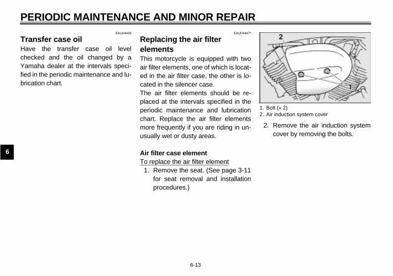
EAU04447*
Replacing the air filter elementsThis motorcycle is equipped with twoair filter elements, one of which is locat-ed in the air filter case, the other is lo-cated in the silencer case.The air filter elements should be re-placed at the intervals specified in theperiodic maintenance and lubricationchart. Replace the air filter elementsmore frequently if you are riding in un-usually wet or dusty areas.
Air filter case elementTo replace the air filter element
1. Remove the seat. (See page 3-11for seat removal and installationprocedures.)
2. Remove the air induction systemcover by removing the bolts.
1. Bolt (× 2)2. Air induction system cover

PERIODIC MAINTENANCE AND MINOR REPAIR
6-14
6
3. Remove the fuel tank as follows.a. Disconnect fuel hose A from the
joint as shown.
b. Remove the nuts. c. Disconnect fuel hose B from thejoint as shown.
ECA00121
CAUTION:_
● Place a towel or cloth under thefuel hose joints when discon-necting hoses A and B to pre-vent fuel from spilling onto thevehicle.
● Make sure that no foreign mate-rial enters the fuel hose jointswhen the hoses are disconnect-ed.
_
1. Fuel hose A 1. Nut (× 2) 1. Fuel hose B

PERIODIC MAINTENANCE AND MINOR REPAIR
6-15
6
d. Remove the hoses as shown, andthen remove the fuel tank by pull-ing it upward.
4. Remove the air filter case bolts.5. Loosen the air filter joint clamp
screw, and then pull off the air filtercase.
1. Hose (× 2) 1. Air filter case2. Bolt (× 2)
1. Air filter joint clamp screw

PERIODIC MAINTENANCE AND MINOR REPAIR
6-16
6
6. Remove the air filter case cover byremoving the screws. 7. Remove the air filter element by
removing the screws.8. Install a new air filter element by
inserting it into the air filter case,then installing the screws.
EC000082*
CAUTION:_
● Make sure that the air filter ele-ment is properly seated in theair filter case.
● The engine should never be op-erated without the air filter ele-ment installed, otherwise thepistons and/or cylinders maybecome excessively worn.
_
9. Remove the clamp from the checkhose, and then remove the plug todrain any accumulated water.
10. Install the plug and the clamp.11. Install the air filter case cover by
installing the screws.12. Install the air filter case by pushing
it onto the air filter joint, and thentightening the air filter joint clampscrew.
13. Install the air filter case by install-ing the bolts.
1. Screw (× 3) 1. Air filter element2. Screw (× 4)
1. Air filter check hose
PERIODIC MAINTENANCE AND MINOR REPAIR
6-17
6
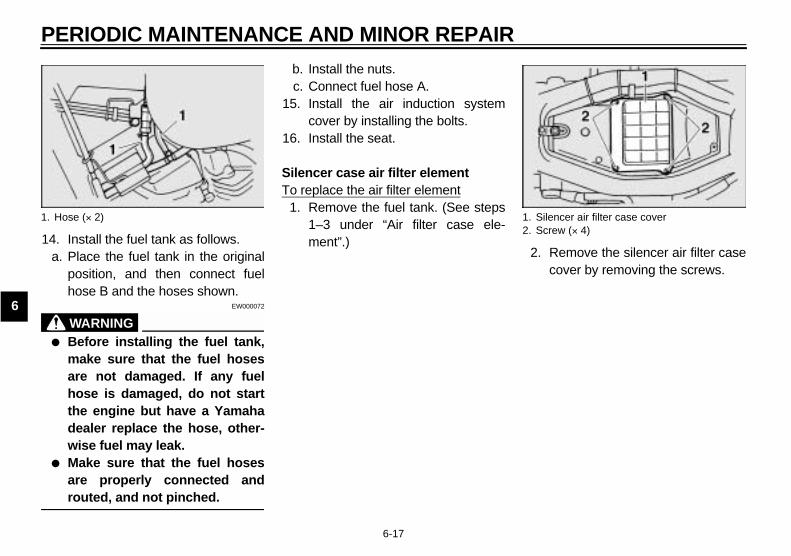
14. Install the fuel tank as follows.a. Place the fuel tank in the original
position, and then connect fuelhose B and the hoses shown.
EW000072
WARNING_
● Before installing the fuel tank,make sure that the fuel hosesare not damaged. If any fuelhose is damaged, do not startthe engine but have a Yamahadealer replace the hose, other-wise fuel may leak.
● Make sure that the fuel hosesare properly connected androuted, and not pinched.
_
b. Install the nuts.c. Connect fuel hose A.
15. Install the air induction systemcover by installing the bolts.
16. Install the seat.
Silencer case air filter elementTo replace the air filter element
1. Remove the fuel tank. (See steps1–3 under “Air filter case ele-ment”.)
2. Remove the silencer air filter casecover by removing the screws.
1. Hose (× 2) 1. Silencer air filter case cover2. Screw (× 4)
PERIODIC MAINTENANCE AND MINOR REPAIR
6-18
6
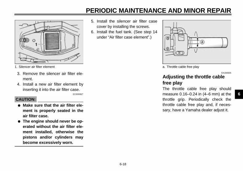
3. Remove the silencer air filter ele-ment.
4. Install a new air filter element byinserting it into the air filter case.
EC000082*
CAUTION:_
● Make sure that the air filter ele-ment is properly seated in theair filter case.
● The engine should never be op-erated without the air filter ele-ment installed, otherwise thepistons and/or cylinders maybecome excessively worn.
_
5. Install the silencer air filter casecover by installing the screws.
6. Install the fuel tank. (See step 14under “Air filter case element”.)
EAU00635
Adjusting the throttle cable free play The throttle cable free play shouldmeasure 0.16–0.24 in (4–6 mm) at thethrottle grip. Periodically check thethrottle cable free play and, if neces-sary, have a Yamaha dealer adjust it.
1. Silencer air filter element a. Throttle cable free play

PERIODIC MAINTENANCE AND MINOR REPAIR
6-19
6
EAU00637
Adjusting the valve clearance The valve clearance changes with use,resulting in improper air-fuel mixtureand/or engine noise. To prevent thisfrom occurring, the valve clearancemust be adjusted by a Yamaha dealerat the intervals specified in the periodicmaintenance and lubrication chart.
EAU03581
TiresTo maximize the performance, durabil-ity, and safe operation of your motor-cycle, note the following pointsregarding the specified tires.
Tire air pressureThe tire air pressure should bechecked and, if necessary, adjustedbefore each ride.
EW000082
WARNING_
● The tire air pressure must bechecked and adjusted on coldtires (i.e., when the temperatureof the tires equals the ambienttemperature).
● The tire air pressure must beadjusted in accordance with theriding speed and with the totalweight of rider, passenger, car-go, and accessories approvedfor this model.
_
CE-22E
CE-16E
Tire air pressure(measured on cold tires)
Load* Front Rear
Up to 198 lb (90 kg)36 psi(2.50 kgf/cm2,250 kPa)
36 psi(2.50 kgf/cm2,250 kPa)
198 lb (90 kg)–maximum
36 psi(2.50 kgf/cm2,250 kPa)
42 psi(2.90 kgf/cm2,290 kPa)
High-speed riding36 psi(2.50 kgf/cm2,250 kPa)
36 psi(2.50 kgf/cm2,250 kPa)
Maximum load* 408 lb (185 kg)
* Total weight of rider, passenger, cargo and accessories

PERIODIC MAINTENANCE AND MINOR REPAIR
6-20
6
EW000083
WARNING_
Proper loading of your motorcycleis important for several characteris-tics of your motorcycle, such ashandling, braking, performance andsafety. Do not carry loosely packeditems that can shift. Securely packyour heaviest items close to thecenter of the motorcycle, and dis-tribute the weight evenly from sideto side. Properly adjust the suspen-sion for your load, and check thecondition and pressure of your tires.NEVER OVERLOAD YOUR MOTOR-CYCLE. Make sure that the totalweight of the cargo, rider, passen-ger, and accessories (cowling, sad-dlebags, etc. if approved for thismodel) does not exceed the maxi-mum load of the motorcycle. Opera-tion of an overloaded motorcyclecould cause tire damage, an acci-dent, or even injury. _
Tire inspectionAlways check the tires before operatingthe motorcycle. If a tire tread showscrosswise lines (minimum tread depth),if the tire has a nail or glass fragmentsin it, or if the sidewall is cracked, con-tact a Yamaha dealer immediately andhave the tire replaced.CE-09E
EW000094
WARNING_
● It is dangerous to ride with aworn-out tire. When a tire treadbegins to show crosswise lines,have a Yamaha dealer replacethe tire immediately.
● The replacement of all wheel-and brake-related parts, includ-ing the tires, should be left to aYamaha dealer, who has thenecessary professional knowl-edge and experience.
_
1. Tire sidewall2. Tire wear indicatora. Tire tread depth
Minimum tire tread depth (front and rear)
0.04 in (1.0 mm)

PERIODIC MAINTENANCE AND MINOR REPAIR
6-21
6
Tire informationThis motorcycle is equipped with castwheels and tubeless tires with valves.
EW000080
WARNING_
● The front and rear tires shouldbe of the same make and de-sign, otherwise the handlingcharacteristics of the motor-cycle cannot be guaranteed.
● After extensive tests, only thetires listed below have been ap-proved for this model byYamaha Motor Co., Ltd.
● Always make sure that the valvecaps are securely installed toprevent air pressure leakage.
● Use only the tire valves andvalve cores listed below toavoid tire deflation during ahigh-speed ride.
_
CE-10E
CE-14E
1. Tire air valve2. Tire air valve core3. Tire air valve cap with seal
FRONT
Manufacturer Size Model
Bridgestone120/70 ZR18 (59W)
BT020F G120/70 ZR18 M/C (59W)
Dunlop120/70 ZR18 (59W)
D220F ST G120/70 ZR18 M/C (59W)
REAR
Manufacturer Size Model
Bridgestone200/50 ZR17 (75W)
BT020R200/50 ZR17 M/C (75W)
Dunlop200/50 ZR17 (75W)
D220 ST200/50 ZR17 M/C (75W)
FRONT & REAR
Tire air valve TR412
Valve core #9000A (original)

PERIODIC MAINTENANCE AND MINOR REPAIR
6-22
6
EAU00684
WARNING_
This motorcycle is fitted with super-high-speed tires. Note the followingpoints in order to make the most ef-ficient use of these tires.
● Use only the specified replace-ment tires. Other tires may runthe danger of bursting at superhigh speeds.
● Brand-new tires can have a rela-tively poor grip on certain roadsurfaces until they have been“broken in”. Therefore, it is ad-visable before doing any high-speed riding to ride conserva-tively for approximately 60 mi(100 km) after installing a newtire.
● The tires must be warmed upbefore a high-speed run.
● Always adjust the tire air pres-sure according to the operatingconditions.
_
EAU03773
Cast wheels To maximize the performance, durabil-ity, and safe operation of your motor-cycle, note the following pointsregarding the specified wheels.
● The wheel rims should be checkedfor cracks, bends or warpage be-fore each ride. If any damage isfound, have a Yamaha dealer re-place the wheel. Do not attempteven the smallest repair to thewheel. A deformed or crackedwheel must be replaced.
● The wheel should be balancedwhenever either the tire or wheelhas been changed or replaced. Anunbalanced wheel can result inpoor performance, adverse han-dling characteristics, and a short-ened tire life.
● Ride at moderate speeds afterchanging a tire since the tire sur-face must first be “broken in” for itto develop its optimal characteris-tics.

PERIODIC MAINTENANCE AND MINOR REPAIR
6-23
6
EAU00691
Accessories and replacement parts
EW000098
WARNING_
This motorcycle is not designed topull a trailer or to be attached to asidecar. The accessories or replace-ment parts you choose for yourmotorcycle should be designed spe-cifically for this model, and theymust be securely mounted to main-tain the inherent stability of the orig-inal design. Genuine Yamaha Partsand Accessories are designed andtested to be compatible with yourmotorcycle. Please consider Genu-ine Yamaha Parts and Accessoriesbefore making a purchase. Use ofnon-Yamaha-approved accessoriesor replacement parts may causeloss of handling stability and ridingsafety.
Since Yamaha cannot control thequality of accessories or parts man-ufactured by other companies,Yamaha cannot be held liable forany consequences caused by theuse of items which have not beenapproved by Yamaha. _
EAU00694
Adjusting the clutch lever free playThe clutch lever free play should mea-sure 0.4–0.6 in (10–15 mm) as shown.Periodically check the clutch lever freeplay and, if necessary, adjust it as fol-lows.
1. Loosen the locknut at the clutch le-ver.
2. To increase the clutch lever freeplay, turn the adjusting bolt in di-rection a. To decrease the clutchlever free play, turn the adjustingbolt in direction b.
1. Locknut2. Clutch lever free play adjusting boltc. Clutch lever free play
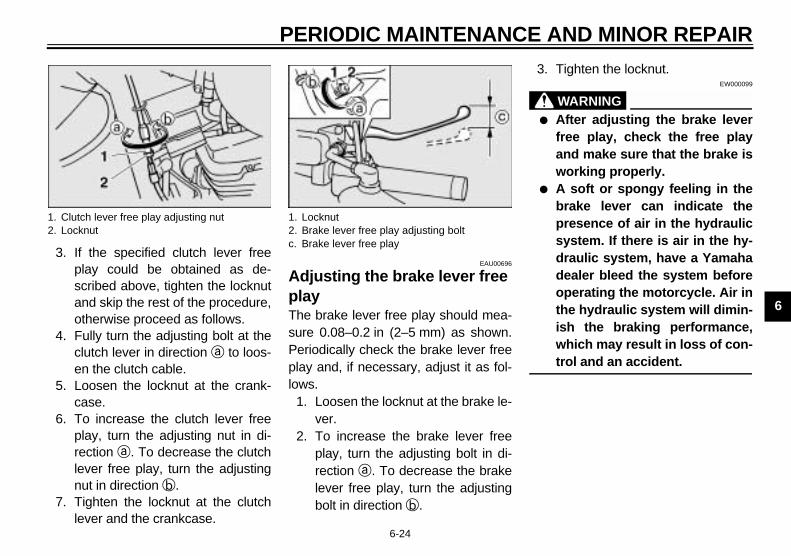
PERIODIC MAINTENANCE AND MINOR REPAIR
6-24
6
3. If the specified clutch lever freeplay could be obtained as de-scribed above, tighten the locknutand skip the rest of the procedure,otherwise proceed as follows.
4. Fully turn the adjusting bolt at theclutch lever in direction a to loos-en the clutch cable.
5. Loosen the locknut at the crank-case.
6. To increase the clutch lever freeplay, turn the adjusting nut in di-rection a. To decrease the clutchlever free play, turn the adjustingnut in direction b.
7. Tighten the locknut at the clutchlever and the crankcase.
EAU00696
Adjusting the brake lever free playThe brake lever free play should mea-sure 0.08–0.2 in (2–5 mm) as shown.Periodically check the brake lever freeplay and, if necessary, adjust it as fol-lows.
1. Loosen the locknut at the brake le-ver.
2. To increase the brake lever freeplay, turn the adjusting bolt in di-rection a. To decrease the brakelever free play, turn the adjustingbolt in direction b.
3. Tighten the locknut.EW000099
WARNING_
● After adjusting the brake leverfree play, check the free playand make sure that the brake isworking properly.
● A soft or spongy feeling in thebrake lever can indicate thepresence of air in the hydraulicsystem. If there is air in the hy-draulic system, have a Yamahadealer bleed the system beforeoperating the motorcycle. Air inthe hydraulic system will dimin-ish the braking performance,which may result in loss of con-trol and an accident.
_
1. Clutch lever free play adjusting nut2. Locknut
1. Locknut2. Brake lever free play adjusting boltc. Brake lever free play

PERIODIC MAINTENANCE AND MINOR REPAIR
6-25
6
EAU01746
Adjusting the brake pedal positionThe top of the brake pedal should be po-sitioned approximately 3.0 in (80 mm)above the top of the footrest as shown.Periodically check the brake pedal posi-tion and, if necessary, have a Yamahadealer adjust it.
EW000109
WARNING_
A soft or spongy feeling in the brakepedal can indicate the presence ofair in the hydraulic system. If thereis air in the hydraulic system, have aYamaha dealer bleed the system be-fore operating the motorcycle. Air inthe hydraulic system will diminishthe braking performance, whichmay result in loss of control and anaccident. _
EAU00713
Adjusting the rear brake light switchThe rear brake light switch, which is ac-tivated by the brake pedal, is properlyadjusted when the brake light comeson just before braking takes effect. Ifnecessary, adjust the brake light switchas follows.Turn the adjusting nut while holding therear brake light switch in place. Tomake the brake light come on earlier,turn the adjusting nut in direction a. Tomake the brake light come on later,turn the adjusting nut in direction b.
a. Distance between brake pedal and footrest 1. Rear brake light switch2. Rear brake light switch adjusting nut

PERIODIC MAINTENANCE AND MINOR REPAIR
6-26
6
EAU00721
Checking the front and rear brake pads The front and rear brake pads must bechecked for wear at the intervals spec-ified in the periodic maintenance andlubrication chart.
EAU00725
Front brake padsEach front brake pad is provided with awear indicator groove, which allowsyou to check the brake pad wear with-out having to disassemble the brake.To check the brake pad wear, checkthe wear indicator groove. If a brakepad has worn to the point that the wearindicator groove has almost disap-peared, have a Yamaha dealer replacethe brake pads as a set.
EAU04434
Rear brake pads1. Remove brake caliper bolt A, loos-
en brake caliper bolt B, and thentilt the caliper forward.
1. Brake pad wear indicator groove
Front
1. Brake caliper bolt A2. Brake caliper bolt B
Rear
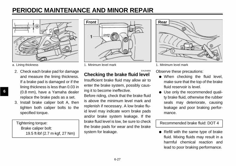
PERIODIC MAINTENANCE AND MINOR REPAIR
6-27
6
2. Check each brake pad for damageand measure the lining thickness.If a brake pad is damaged or if thelining thickness is less than 0.03 in(0.8 mm), have a Yamaha dealerreplace the brake pads as a set.
3. Install brake caliper bolt A, thentighten both caliper bolts to thespecified torque.
EAU04856
Checking the brake fluid level Insufficient brake fluid may allow air toenter the brake system, possibly caus-ing it to become ineffective.Before riding, check that the brake fluidis above the minimum level mark andreplenish if necessary. A low brake flu-id level may indicate worn brake padsand/or brake system leakage. If thebrake fluid level is low, be sure to checkthe brake pads for wear and the brakesystem for leakage.
Observe these precautions:● When checking the fluid level,
make sure that the top of the brakefluid reservoir is level.
● Use only the recommended quali-ty brake fluid, otherwise the rubberseals may deteriorate, causingleakage and poor braking perfor-mance.
● Refill with the same type of brakefluid. Mixing fluids may result in aharmful chemical reaction andlead to poor braking performance.
a. Lining thickness
Tightening torque:Brake caliper bolt:
19.5 ft·lbf (2.7 m·kgf, 27 Nm)
1. Minimum level mark
Front
1. Minimum level mark
Recommended brake fluid: DOT 4
Rear

PERIODIC MAINTENANCE AND MINOR REPAIR
6-28
6
● Be careful that water does not en-ter the brake fluid reservoir whenrefilling. Water will significantlylower the boiling point of the fluidand may result in vapor lock.
● Brake fluid may deteriorate paint-ed surfaces or plastic parts. Al-ways clean up spilled fluidimmediately.
● As the brake pads wear, it is nor-mal for the brake fluid level togradually go down. However, if thebrake fluid level goes down sud-denly, have a Yamaha dealercheck the cause.
EAU03976
Changing the brake fluid Have a Yamaha dealer change thebrake fluid at the intervals specified inthe NOTE after the periodic mainte-nance and lubrication chart. In addition,have the oil seals of the master cylin-ders and calipers as well as the brakehoses replaced at the intervals listedbelow or whenever they are damagedor leaking.
● Oil seals: Replace every twoyears.
● Brake hoses: Replace every fouryears.
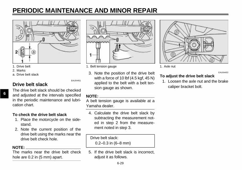
PERIODIC MAINTENANCE AND MINOR REPAIR
6-29
6
EAU04451
Drive belt slack The drive belt slack should be checkedand adjusted at the intervals specifiedin the periodic maintenance and lubri-cation chart.
To check the drive belt slack 1. Place the motorcycle on the side-
stand.2. Note the current position of the
drive belt using the marks near thedrive belt check hole.
NOTE:_
The marks near the drive belt checkhole are 0.2 in (5 mm) apart. _
3. Note the position of the drive beltwith a force of 10 lbf (4.5 kgf, 45 N)applied to the belt with a belt ten-sion gauge as shown.
NOTE:_
A belt tension gauge is available at aYamaha dealer. _
4. Calculate the drive belt slack bysubtracting the measurement not-ed in step 2 from the measure-ment noted in step 3.
5. If the drive belt slack is incorrect,adjust it as follows.
EAU04453
To adjust the drive belt slack 1. Loosen the axle nut and the brake
caliper bracket bolt.
1. Drive belt2. Marksa. Drive belt slack
1. Belt tension gauge
Drive belt slack:0.2–0.3 in (6–8 mm)
1. Axle nut
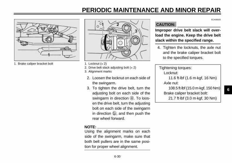
PERIODIC MAINTENANCE AND MINOR REPAIR
6-30
6
2. Loosen the locknut on each side ofthe swingarm.
3. To tighten the drive belt, turn theadjusting bolt on each side of theswingarm in direction a. To loos-en the drive belt, turn the adjustingbolt on each side of the swingarmin direction b, and then push therear wheel forward.
NOTE:_
Using the alignment marks on eachside of the swingarm, make sure thatboth belt pullers are in the same posi-tion for proper wheel alignment. _
ECA00025
CAUTION:_
Improper drive belt slack will over-load the engine. Keep the drive beltslack within the specified range. _
4. Tighten the locknuts, the axle nutand the brake caliper bracket boltto the specified torques.
1. Brake caliper bracket bolt 1. Locknut (× 2)2. Drive belt slack adjusting bolt (× 2)3. Alignment marks
Tightening torques:Locknut:
11.6 ft·lbf (1.6 m·kgf, 16 Nm)Axle nut:
108.5 ft·lbf (15.0 m·kgf, 150 Nm)Brake caliper bracket bolt:
21.7 ft·lbf (3.0 m·kgf, 30 Nm)

PERIODIC MAINTENANCE AND MINOR REPAIR
6-31
6
EAU03297
Checking and lubricating the cablesThe operation of all control cables andthe condition of the cables should bechecked before each ride, and the ca-bles and cable ends should be lubricat-ed if necessary. If a cable is damagedor does not move smoothly, have aYamaha dealer check or replace it.
EW000111
WARNING_
Damage to the outer housing of ca-bles may result in internal rustingand cause interference with cablemovement. Replace damaged ca-bles as soon as possible to preventunsafe conditions. _
EAU04034
Checking and lubricating the throttle grip and cable The operation of the throttle grip shouldbe checked before each ride. In addi-tion, the cable should be lubricated orreplaced at the intervals specified inthe periodic maintenance chart.
EAU03370
Checking and lubricating the brake and shift pedals The operation of the brake and shiftpedals should be checked before eachride, and the pedal pivots should be lu-bricated if necessary.
Recommended lubricant:Yamaha Chain and Cable Lube or engine oil SAE 10W-30 (API SE)
Recommended lubricant:Lithium-soap-based grease (all-purpose grease)

PERIODIC MAINTENANCE AND MINOR REPAIR
6-32
6
EAU03164
Checking and lubricating the brake and clutch levers The operation of the brake and clutchlevers should be checked before eachride, and the lever pivots should be lu-bricated if necessary.
Recommended lubricant:Lithium-soap-based grease (all-purpose grease)

PERIODIC MAINTENANCE AND MINOR REPAIR
6-33
6
EAU03165
Checking and lubricating the sidestandThe operation of the sidestand shouldbe checked before each ride, and thesidestand pivot and metal-to-metalcontact surfaces should be lubricated ifnecessary.
EW000113
WARNING_
If the sidestand does not move upand down smoothly, have a Yamahadealer check or repair it. _
EAU04282
Lubricating the rear suspensionThe pivoting points of the rear suspen-sion must be lubricated at the intervalsspecified in the periodic maintenanceand lubrication chart.
EAU02939
Checking the front fork The condition and operation of the frontfork must be checked as follows at theintervals specified in the periodic main-tenance and lubrication chart.
To check the conditionEW000115
WARNING_
Securely support the motorcycle sothat there is no danger of it fallingover. _
Check the inner tubes for scratches,damage and excessive oil leakage.
Recommended lubricant:Lithium-soap-based grease (all-purpose grease)
Recommended lubricant:Lithium-soap-based grease
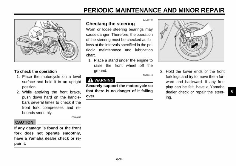
PERIODIC MAINTENANCE AND MINOR REPAIR
6-34
6
To check the operation1. Place the motorcycle on a level
surface and hold it in an uprightposition.
2. While applying the front brake,push down hard on the handle-bars several times to check if thefront fork compresses and re-bounds smoothly.
EC000098
CAUTION:_
If any damage is found or the frontfork does not operate smoothly,have a Yamaha dealer check or re-pair it. _
EAU00794
Checking the steering Worn or loose steering bearings maycause danger. Therefore, the operationof the steering must be checked as fol-lows at the intervals specified in the pe-riodic maintenance and lubricationchart.
1. Place a stand under the engine toraise the front wheel off theground.
EW000115
WARNING_
Securely support the motorcycle sothat there is no danger of it fallingover._
2. Hold the lower ends of the frontfork legs and try to move them for-ward and backward. If any freeplay can be felt, have a Yamahadealer check or repair the steer-ing.

PERIODIC MAINTENANCE AND MINOR REPAIR
6-35
6
EAU01144
Checking the wheel bearings The front and rear wheel bearings mustbe checked at the intervals specified inthe periodic maintenance and lubrica-tion chart. If there is play in the wheelhub or if the wheel does not turnsmoothly, have a Yamaha dealercheck the wheel bearings.
EAU00800
BatteryThis motorcycle is equipped with asealed-type (MF) battery, which doesnot require any maintenance. There isno need to check the electrolyte or toadd distilled water.
EC000101
CAUTION:_
Never attempt to remove the batterycell seals, as this would permanent-ly damage the battery. _
EW000116
WARNING_
● Electrolyte is poisonous anddangerous since it contains sul-furic acid, which causes severeburns. Avoid any contact withskin, eyes or clothing and al-ways shield your eyes whenworking near batteries. In caseof contact, administer the fol-lowing FIRST AID.• EXTERNAL: Flush with plenty
of water.• INTERNAL: Drink large quan-
tities of water or milk and im-mediately call a physician.
• EYES: Flush with water for15 minutes and seek promptmedical attention.
● Batteries produce explosive hy-drogen gas. Therefore, keepsparks, flames, cigarettes, etc.,away from the battery and pro-vide sufficient ventilation whencharging it in an enclosed space.
● KEEP THIS AND ALL BATTER-IES OUT OF THE REACH OFCHILDREN.
_
1. Battery

PERIODIC MAINTENANCE AND MINOR REPAIR
6-36
6
To charge the batteryHave a Yamaha dealer charge the bat-tery as soon as possible if it seems tohave discharged. Keep in mind that thebattery tends to discharge more quicklyif the motorcycle is equipped with op-tional electrical accessories.
To store the battery1. If the motorcycle will not be used
for more than one month, removethe battery, fully charge it, andthen place it in a cool, dry place.
2. If the battery will be stored formore than two months, check it atleast once a month and fullycharge it if necessary.
3. Fully charge the battery before in-stallation.
4. After installation, make sure thatthe battery leads are properly con-nected to the battery terminals.
EC000102
CAUTION:_
● Always keep the batterycharged. Storing a dischargedbattery can cause permanentbattery damage.
● To charge a sealed-type (MF)battery, a special (constant-voltage) battery charger is re-quired. Using a conventionalbattery charger will damage thebattery. If you do not have ac-cess to a sealed-type (MF) bat-tery charger, have a Yamahadealer charge your battery.
_

PERIODIC MAINTENANCE AND MINOR REPAIR
6-37
6
EAU04874
Replacing the fuses The main fuse and the fuse box, whichcontains the fuses for the individual cir-cuits, are located under the seat. (Seepage 3-11 for seat removal and instal-lation procedures.)If a fuse is blown, replace it as follows.
1. Unhook the battery band, and thenremove the battery cover.
2. Turn the key to “OFF” and turn offthe electrical circuit in question.
3. Remove the blown fuse, and theninstall a new fuse of the specifiedamperage.
1. Battery band2. Battery cover
1. Headlight fuse2. Signaling system fuse3. Ignition fuse4. Electronic fuel injection fuse5. Odometer and clock fuse (backup fuse)6. Auto-decompression fuse7. Spare fuse (× 3)8. ECU fuse
1. Main fuse2. Spare main fuse
Specified fuses:Main fuse: 30 AHeadlight fuse: 15 ASignaling system fuse: 10 AIgnition fuse: 10 AElectronic fuel injection fuse: 15 AECU fuse: 10 AAuto-decompressionfuse: 15AOdometer and clock fuse (backup fuse): 7.5 A

PERIODIC MAINTENANCE AND MINOR REPAIR
6-38
6
EC000103
CAUTION:_
Do not use a fuse of a higher amper-age rating than recommended toavoid causing extensive damage tothe electrical system and possibly afire. _
4. Turn the key to “ON” and turn onthe electrical circuit in question tocheck if the device operates.
5. If the fuse immediately blowsagain, have a Yamaha dealercheck the electrical system.
6. Install the battery cover, and thenhook the battery band onto theholder.
EAU04189
Replacing the headlight bulb This motorcycle is equipped with aquartz bulb headlight. If the headlightbulb burns out, replace it as follows.
1. Remove the headlight unit by re-moving the screws.
2. Disconnect the headlight coupler,and then remove the bulb cover.
1. Screw (× 2) 1. Headlight coupler2. Headlight bulb cover
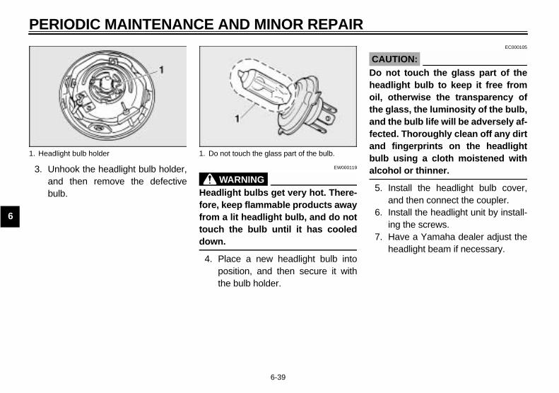
PERIODIC MAINTENANCE AND MINOR REPAIR
6-39
6
3. Unhook the headlight bulb holder,and then remove the defectivebulb.
EW000119
WARNING_
Headlight bulbs get very hot. There-fore, keep flammable products awayfrom a lit headlight bulb, and do nottouch the bulb until it has cooleddown._
4. Place a new headlight bulb intoposition, and then secure it withthe bulb holder.
EC000105
CAUTION:_
Do not touch the glass part of theheadlight bulb to keep it free fromoil, otherwise the transparency ofthe glass, the luminosity of the bulb,and the bulb life will be adversely af-fected. Thoroughly clean off any dirtand fingerprints on the headlightbulb using a cloth moistened withalcohol or thinner. _
5. Install the headlight bulb cover,and then connect the coupler.
6. Install the headlight unit by install-ing the screws.
7. Have a Yamaha dealer adjust theheadlight beam if necessary.
1. Headlight bulb holder 1. Do not touch the glass part of the bulb.
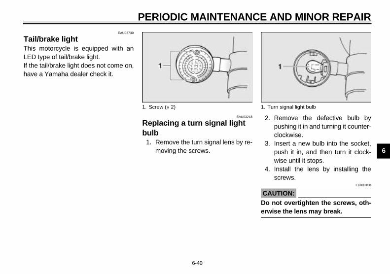
PERIODIC MAINTENANCE AND MINOR REPAIR
6-40
6
EAU03730
Tail/brake light This motorcycle is equipped with anLED type of tail/brake light. If the tail/brake light does not come on,have a Yamaha dealer check it.
EAU03218
Replacing a turn signal light bulb
1. Remove the turn signal lens by re-moving the screws.
2. Remove the defective bulb bypushing it in and turning it counter-clockwise.
3. Insert a new bulb into the socket,push it in, and then turn it clock-wise until it stops.
4. Install the lens by installing thescrews.
EC000108
CAUTION:_
Do not overtighten the screws, oth-erwise the lens may break. _
1. Screw (× 2) 1. Turn signal light bulb
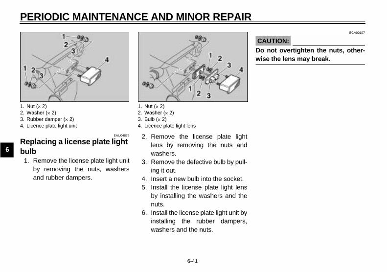
PERIODIC MAINTENANCE AND MINOR REPAIR
6-41
6
EAU04875
Replacing a license plate light bulb
1. Remove the license plate light unitby removing the nuts, washersand rubber dampers.
2. Remove the license plate lightlens by removing the nuts andwashers.
3. Remove the defective bulb by pull-ing it out.
4. Insert a new bulb into the socket.5. Install the license plate light lens
by installing the washers and thenuts.
6. Install the license plate light unit byinstalling the rubber dampers,washers and the nuts.
ECA00107
CAUTION:_
Do not overtighten the nuts, other-wise the lens may break. _
1. Nut (× 2)2. Washer (× 2)3. Rubber damper (× 2)4. Licence plate light unit
1. Nut (× 2)2. Washer (× 2)3. Bulb (× 2)4. Licence plate light lens

PERIODIC MAINTENANCE AND MINOR REPAIR
6-42
6
EAU01579
Supporting the motorcycle Since this model is not equipped with acenterstand, follow these precautionswhen removing the front and rearwheel or performing other mainte-nance requiring the motorcycle tostand upright. Check that the motor-cycle is in a stable and level positionbefore starting any maintenance. Astrong wooden box can be placed un-der the engine for added stability.
To service the front wheel1. Stabilize the rear of the motorcycle
by using a motorcycle stand or, ifan additional motorcycle stand isnot available, by placing a jack un-der the frame in front of the rearwheel.
2. Raise the front wheel off theground by using a motorcyclestand.
To service the rear wheelRaise the rear wheel off the ground byusing a motorcycle stand or, if a motor-cycle stand is not available, by placinga jack either under each side of theframe in front of the rear wheel or undereach side of the swingarm.
EAU01008
TroubleshootingAlthough Yamaha motorcycles receivea thorough inspection before shipmentfrom the factory, trouble may occur dur-ing operation. Any problem in the fuel,compression, or ignition systems, forexample, can cause poor starting andloss of power.The following troubleshooting chartrepresents a quick and easy procedurefor checking these vital systems your-self. However, should your motorcyclerequire any repair, take it to a Yamahadealer, whose skilled technicians havethe necessary tools, experience, andknow-how to service the motorcycleproperly.Use only genuine Yamaha replace-ment parts. Imitation parts may looklike Yamaha parts, but they are ofteninferior, have a shorter service life andcan lead to expensive repair bills.

PERIODIC MAINTENANCE AND MINOR REPAIR
6-43
6
EAU01297
Troubleshooting chart EW000125
WARNING_
Keep away open flames and do not smoke while checking or working on the fuel system. _
Check the fuel level inthe fuel tank.
1. FuelThere is enough fuel.
There is no fuel.
Check the compression.
Supply fuel. The engine does not start. Check the compression.
Operate the electric starter.
2. CompressionThere is compression.
There is no compression.
Check the ignition.
Have a Yamaha dealercheck the vehicle.
Remove the spark plugsand check the electrodes.
3. Ignition Wipe off with a dry cloth and correct thespark plug gaps, or replace the spark plugs.
Have a Yamaha dealer check the vehicle.
The engine does not start.Have a Yamaha dealercheck the vehicle.
The engine does not start.Check the battery.
Operate the electric starter.
4. BatteryThe engine turns over quickly.
The engine turns over slowly.
The battery is good.
Check the battery lead connections,and charge the battery if necessary.
Dry
WetOpen the throttle halfway and operatethe electric starter.
MOTORCYCLE CARE AND STORAGE
7
Care .................................................................................................. 7-1Storage .............................................................................................. 7-4
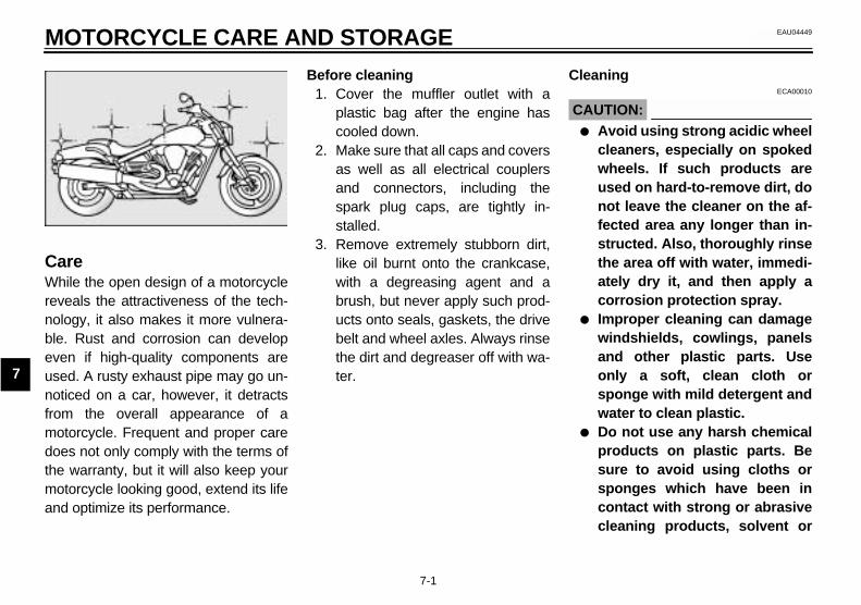
7-1
7
EAU04449
7-MOTORCYCLE CARE AND STORAGE
CareWhile the open design of a motorcyclereveals the attractiveness of the tech-nology, it also makes it more vulnera-ble. Rust and corrosion can developeven if high-quality components areused. A rusty exhaust pipe may go un-noticed on a car, however, it detractsfrom the overall appearance of amotorcycle. Frequent and proper caredoes not only comply with the terms ofthe warranty, but it will also keep yourmotorcycle looking good, extend its lifeand optimize its performance.
Before cleaning1. Cover the muffler outlet with a
plastic bag after the engine hascooled down.
2. Make sure that all caps and coversas well as all electrical couplersand connectors, including thespark plug caps, are tightly in-stalled.
3. Remove extremely stubborn dirt,like oil burnt onto the crankcase,with a degreasing agent and abrush, but never apply such prod-ucts onto seals, gaskets, the drivebelt and wheel axles. Always rinsethe dirt and degreaser off with wa-ter.
CleaningECA00010
CAUTION:_
● Avoid using strong acidic wheelcleaners, especially on spokedwheels. If such products areused on hard-to-remove dirt, donot leave the cleaner on the af-fected area any longer than in-structed. Also, thoroughly rinsethe area off with water, immedi-ately dry it, and then apply acorrosion protection spray.
● Improper cleaning can damagewindshields, cowlings, panelsand other plastic parts. Useonly a soft, clean cloth orsponge with mild detergent andwater to clean plastic.
● Do not use any harsh chemicalproducts on plastic parts. Besure to avoid using cloths orsponges which have been incontact with strong or abrasivecleaning products, solvent or

MOTORCYCLE CARE AND STORAGE
7-2
7
thinner, fuel (gasoline), rust re-movers or inhibitors, brake flu-id, antifreeze or electrolyte.
● Do not use high-pressure wash-ers or steam-jet cleaners sincethey cause water seepage anddeterioration in the following ar-eas: seals (of wheel and swing-arm bearings, fork and brakes),electric components (couplers,connectors, instruments,switches and lights), breatherhoses and vents.
● For motorcycles equipped witha windshield: Do not use strongcleaners or hard sponges asthey will cause dulling orscratching. Some cleaningcompounds for plastic mayleave scratches on the wind-shield. Test the product on asmall hidden part of the wind-shield to make sure that it doesnot leave any marks. If the wind-
shield is scratched, use a quali-ty plastic polishing compoundafter washing.
_
After normal useRemove dirt with warm water, a milddetergent, and a soft, clean sponge,and then rinse thoroughly with cleanwater. Use a toothbrush or bottlebrushfor hard-to-reach areas. Stubborn dirtand insects will come off more easily ifthe area is covered with a wet cloth fora few minutes before cleaning.
After riding in the rain, near the sea oron salt-sprayed roadsSince sea salt or salt sprayed on roadsduring winter are extremely corrosive incombination with water, carry out thefollowing steps after each ride in therain, near the sea or on salt-sprayedroads.
NOTE:_
Salt sprayed on roads in the winter mayremain well into spring. _
1. Clean the motorcycle with coldwater and a mild detergent, afterthe engine has cooled down.
ECA00012
CAUTION:_
Do not use warm water since it in-creases the corrosive action of thesalt. _
2. After drying the motorcycle, applya corrosion protection spray on allmetal, including chrome- and nick-el-plated, surfaces to prevent cor-rosion.

MOTORCYCLE CARE AND STORAGE
7-3
7
After cleaning1. Dry the motorcycle with a chamois
or an absorbing cloth.2. Use a chrome polish to shine
chrome, aluminum and stainless-steel parts, including the exhaustsystem. (Even the thermally in-duced discoloring of stainless-steel exhaust systems can be re-moved through polishing.)
3. To prevent corrosion, it is recom-mended to apply a corrosion pro-tection spray on all metal,including chrome- and nickel-plat-ed, surfaces.
4. Use spray oil as a universal clean-er to remove any remaining dirt.
5. Touch up minor paint damagecaused by stones, etc.
6. Wax all painted and chrome-plat-ed surfaces. Avoid combinationcleaner waxes, many of whichcontain abrasives that may marthe paint or protective finish.
7. Let the motorcycle dry completelybefore storing or covering it.
EWA00001
WARNING_
● Make sure that there is no oil orwax on the brakes or tires. Ifnecessary, clean the brakediscs and brake linings with aregular brake disc cleaner or ac-etone, and wash the tires withwarm water and a mild deter-gent.
● Before operating the motor-cycle, test its braking perfor-mance and cornering behavior.
_
ECA00033
CAUTION:_
● Apply spray oil and wax spar-ingly and make sure to wipe offany excess.
● Never apply oil or wax to thedrive belt.
● Never apply oil or wax to anyrubber and plastic parts, buttreat them with a suitable careproduct.
● Avoid using abrasive polishingcompounds as they will wearaway the paint.
_
NOTE:_
Consult a Yamaha dealer for advice onwhat products to use. _
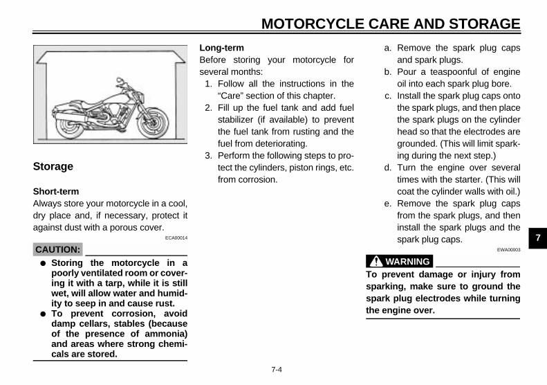
MOTORCYCLE CARE AND STORAGE
7-4
7
Storage
Short-termAlways store your motorcycle in a cool,dry place and, if necessary, protect itagainst dust with a porous cover.
ECA00014
CAUTION:_
● Storing the motorcycle in apoorly ventilated room or cover-ing it with a tarp, while it is stillwet, will allow water and humid-ity to seep in and cause rust.
● To prevent corrosion, avoiddamp cellars, stables (becauseof the presence of ammonia)and areas where strong chemi-cals are stored.
_
Long-termBefore storing your motorcycle forseveral months:
1. Follow all the instructions in the“Care” section of this chapter.
2. Fill up the fuel tank and add fuelstabilizer (if available) to preventthe fuel tank from rusting and thefuel from deteriorating.
3. Perform the following steps to pro-tect the cylinders, piston rings, etc.from corrosion.
a. Remove the spark plug capsand spark plugs.
b. Pour a teaspoonful of engineoil into each spark plug bore.
c. Install the spark plug caps ontothe spark plugs, and then placethe spark plugs on the cylinderhead so that the electrodes aregrounded. (This will limit spark-ing during the next step.)
d. Turn the engine over severaltimes with the starter. (This willcoat the cylinder walls with oil.)
e. Remove the spark plug capsfrom the spark plugs, and theninstall the spark plugs and thespark plug caps.
EWA00003
WARNING_
To prevent damage or injury fromsparking, make sure to ground thespark plug electrodes while turningthe engine over. _

MOTORCYCLE CARE AND STORAGE
7-5
7
4. Lubricate all control cables andthe pivoting points of all levers andpedals as well as of the sidestand/centerstand.
5. Check and, if necessary, correctthe tire air pressure, and then liftthe motorcycle so that both of itswheels are off the ground. Alterna-tively, turn the wheels a little everymonth in order to prevent the tiresfrom becoming degraded in onespot.
6. Cover the muffler outlet with aplastic bag to prevent moisturefrom entering it.
7. Remove the battery and fullycharge it. Store it in a cool, dryplace and charge it once a month.Do not store the battery in an ex-cessively cold or warm place [lessthan 30 °F (0 °C) or more than90 °F (30 °C)]. For more informa-tion on storing the battery, seepage 6-36.
NOTE:_
Make any necessary repairs beforestoring the motorcycle.
SPECIFICATIONS
8
Specifications .................................................................................... 8-1
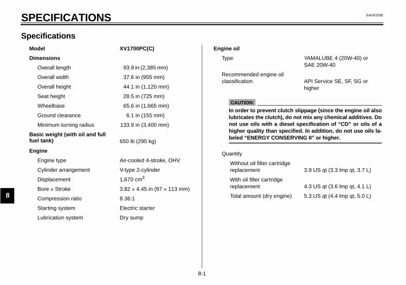
8-1
8
EAU01038
8-SPECIFICATIONS
SpecificationsCS-01E
Model XV1700PC(C)
Dimensions
Overall length 93.9 in (2,385 mm)
Overall width 37.6 in (955 mm)
Overall height 44.1 in (1,120 mm)
Seat height 28.5 in (725 mm)
Wheelbase 65.6 in (1,665 mm)
Ground clearance 6.1 in (155 mm)
Minimum turning radius 133.9 in (3,400 mm)
Basic weight (with oil and full fuel tank) 650 lb (295 kg)
Engine
Engine type Air-cooled 4-stroke, OHV
Cylinder arrangement V-type 2-cylinder
Displacement 1,670 cm3
Bore × Stroke 3.82 × 4.45 in (97 × 113 mm)
Compression ratio 8.36:1
Starting system Electric starter
Lubrication system Dry sump
Engine oil
Type YAMALUBE 4 (20W-40) or SAE 20W-40
Recommended engine oil classification API Service SE, SF, SG or
higher
Quantity
Without oil filter cartridge replacement 3.9 US qt (3.3 lmp qt, 3.7 L)
With oil filter cartridge replacement 4.3 US qt (3.6 lmp qt, 4.1 L)
Total amount (dry engine) 5.3 US qt (4.4 lmp qt, 5.0 L)
CAUTION:
In order to prevent clutch slippage (since the engine oil alsolubricates the clutch), do not mix any chemical additives. Donot use oils with a diesel specification of “CD” or oils of ahigher quality than specified. In addition, do not use oils la-beled “ENERGY CONSERVING II” or higher.
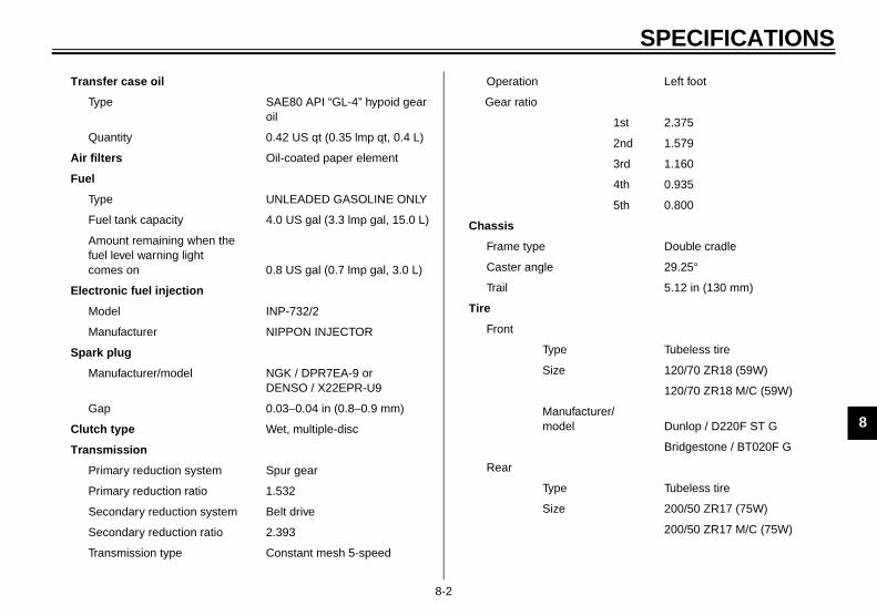
SPECIFICATIONS
8-2
8
Transfer case oil
Type SAE80 API “GL-4” hypoid gear oil
Quantity 0.42 US qt (0.35 lmp qt, 0.4 L)
Air filters Oil-coated paper element
Fuel
Type UNLEADED GASOLINE ONLY
Fuel tank capacity 4.0 US gal (3.3 lmp gal, 15.0 L)
Amount remaining when the fuel level warning light comes on 0.8 US gal (0.7 lmp gal, 3.0 L)
Electronic fuel injection
Model INP-732/2
Manufacturer NIPPON INJECTOR
Spark plug
Manufacturer/model NGK / DPR7EA-9 or DENSO / X22EPR-U9
Gap 0.03–0.04 in (0.8–0.9 mm)
Clutch type Wet, multiple-disc
Transmission
Primary reduction system Spur gear
Primary reduction ratio 1.532
Secondary reduction system Belt drive
Secondary reduction ratio 2.393
Transmission type Constant mesh 5-speed
Operation Left foot
Gear ratio
1st 2.375
2nd 1.579
3rd 1.160
4th 0.935
5th 0.800
Chassis
Frame type Double cradle
Caster angle 29.25°
Trail 5.12 in (130 mm)
Tire
Front
Type Tubeless tire
Size 120/70 ZR18 (59W)
120/70 ZR18 M/C (59W)
Manufacturer/ model Dunlop / D220F ST G
Bridgestone / BT020F G
Rear
Type Tubeless tire
Size 200/50 ZR17 (75W)
200/50 ZR17 M/C (75W)

SPECIFICATIONS
8-3
8
Manufacturer/ model Dunlop / D220 ST
Bridgestone / BT020R
Maximum load* 408 lb (185 kg)
Tire air pressure (measured on cold tires)
Up to 198 lb (90 kg)*
Front 36 psi (2.50 kgf/cm2, 250 kPa)
Rear 36 psi (2.50 kgf/cm2, 250 kPa)
198 lb (90 kg)–maximum*
Front 36 psi (2.50 kgf/cm2, 250 kPa)
Rear 42 psi (2.90 kgf/cm2, 290 kPa)
High-speed riding
Front 36 psi (2.50 kgf/cm2, 250 kPa)
Rear 36 psi (2.50 kgf/cm2, 250 kPa)
* Total weight of rider, passenger, cargo and accessories
Wheels
Front
Type Cast wheel
Size 18 × MT 3.50
18 M/C × MT 3.50
Rear
Type Cast wheel
Size 17 × MT 6.00
17 M/C × MT 6.00
Brakes
Front
Type Dual disc brake
Operation Right hand
Fluid DOT 4
Rear
Type Single disc brake
Operation Right foot
Fluid DOT 4
Suspension
Front Telescopic fork
Rear Swingarm (link suspension)
Spring/Shock absorber
Front Coil spring / oil damper
Rear Coil spring / gas-oil damper
Wheel travel
Front 5.3 in (135 mm)
Rear 4.3 in (110 mm)
Electrical
Ignition system T.C.I. (digital)
Charging system
Type A.C. magneto
Standard output 14 V, 31 A @ 5,000 r/min

SPECIFICATIONS
8-4
8
Battery
Model GT14B-4
Voltage, capacity 12 V, 12 Ah
Headlight type Halogen bulb
Bulb voltage, wattage × quantity
Headlight 12 V, 60/55 W × 1
Tail/brake light LED
License plate light 12 V, 5 W × 2
Front turn signal/position light 12 V, 23/8 W × 2
Rear turn signal light 12 V, 23 W × 2
Meter lighting LED
Neutral indicator light LED
High beam indicator light LED
Turn signal indicator light LED × 2
Fuel level warning light LED
Engine trouble warning light LED
Fuses
Main fuse 30 A
Ignition fuse 10 A
Signaling system fuse 10 A
Headlight fuse 15 A
Electronic fuel injection fuse 15 A
ECU fuse 10 A
Auto-decompression fuse 15 A
Odometer and clock fuse (backup fuse) 7.5 A


CONSUMER INFORMATION
9
Identification numbers ....................................................................... 9-1Key identification number .................................................................. 9-1Vehicle identification number ............................................................. 9-1Model label ........................................................................................ 9-2Reporting safety defects ................................................................... 9-3Motorcycle noise regulation .............................................................. 9-4Maintenance record .......................................................................... 9-5YAMAHA MOTOR CORPORATION, U.S.A. STREET AND
ENDURO MOTORCYCLE LIMITED WARRANTY .......................... 9-7YAMAHA EXTENDED SERVICE (Y.E.S.) ......................................... 9-9

9-1
9
EAU01039
9-CONSUMER INFORMATIONEAU02944
Identification numbers Record the key identification number,vehicle identification number and mod-el label information in the spaces pro-vided below for assistance whenordering spare parts from a Yamahadealer or for reference in case the vehi-cle is stolen.
1. KEY IDENTIFICATION NUMBER:CA-02E
2. VEHICLE IDENTIFICATION NUMBER:
CA-02E
3. MODEL LABEL INFORMATION:CA-01E
EAU01041
Key identification number The key identification number isstamped into the key tag. Record thisnumber in the space provided and useit for reference when ordering a newkey.
EAU01043
Vehicle identification number The vehicle identification number isstamped into the steering head pipe.Record this number in the space pro-vided.
NOTE:_
The vehicle identification number isused to identify your motorcycle andmay be used to register your motor-cycle with the licensing authority inyour area. _
1. Key identification number 1. Vehicle identification number

CONSUMER INFORMATION
9-2
9
EAU01050
Model label The model label is affixed to the frameunder the seat. (See page 3-11 for seatremoval and installation procedures.)Record the information on this label inthe space provided. This informationwill be needed when ordering spareparts from a Yamaha dealer.
1. Model label

CONSUMER INFORMATION
9-3
9
EAU01051
Reporting safety defects If you believe that your vehicle has a defect which could cause a crash or could cause injury or death, you should immedi-ately inform the National Highway Traffic Safety Administration (NHTSA) in addition to notifying Yamaha Motor Corporation,U.S.A. If NHTSA receives similar complaints, it may open an investigation, and if it finds that a safety defect exists in a groupof vehicles, it may order a recall and remedy campaign. However, NHTSA cannot become involved in individual problemsbetween you, your dealer, or Yamaha Motor Corporation, U.S.A.
To contact NHTSA, you may either call the Auto Safety Hotline toll-free at 1-800-424-9393 (or 366-0123 in Washington, D.C.area) or write to: NHTSA, U.S. Department of Transportation, Washington, D.C. 20590. You can also obtain other informa-tion about motor vehicle safety from the Hotline.

CONSUMER INFORMATION
9-4
9
EAU01053
Motorcycle noise regulation TAMPERING WITH NOISE CONTROL SYSTEM PROHIBITED:Federal law prohibits the following acts or the causing thereof: (1) The removal or rendering inoperative by any person otherthan for purposes of maintenance, repair, or replacement of any device or element of design incorporated into any new ve-hicle for the purpose of noise control prior to its sale or delivery to the ultimate purchaser or while it is in use or (2) the use ofthe vehicle after such device or element of design has been removed or rendered inoperative by any person.
“AMONG THOSE ACTS PRESUMED TO CONSTITUTE TAMPERING ARE THE ACTS LISTED BELOW”.
These acts include tampering with the following systems; i.e., modification, removal, etc.CL-01E
Exhaust systemMufflerExhaust pipeSilencer
Intake systemAir cleaner caseAir cleaner elementIntake duct
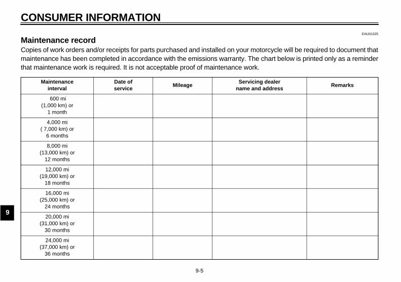
CONSUMER INFORMATION
9-5
9
EAU01325
Maintenance record Copies of work orders and/or receipts for parts purchased and installed on your motorcycle will be required to document thatmaintenance has been completed in accordance with the emissions warranty. The chart below is printed only as a reminderthat maintenance work is required. It is not acceptable proof of maintenance work.CL-04E
Maintenanceinterval
Date ofservice
MileageServicing dealer
name and addressRemarks
600 mi(1,000 km) or
1 month
4,000 mi( 7,000 km) or
6 months
8,000 mi(13,000 km) or
12 months
12,000 mi(19,000 km) or
18 months
16,000 mi(25,000 km) or
24 months
20,000 mi(31,000 km) or
30 months
24,000 mi(37,000 km) or
36 months
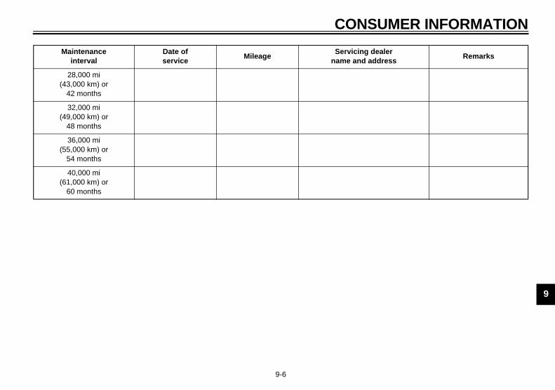
CONSUMER INFORMATION
9-6
9
28,000 mi(43,000 km) or
42 months
32,000 mi(49,000 km) or
48 months
36,000 mi(55,000 km) or
54 months
40,000 mi(61,000 km) or
60 months
Maintenanceinterval
Date ofservice
MileageServicing dealer
name and addressRemarks
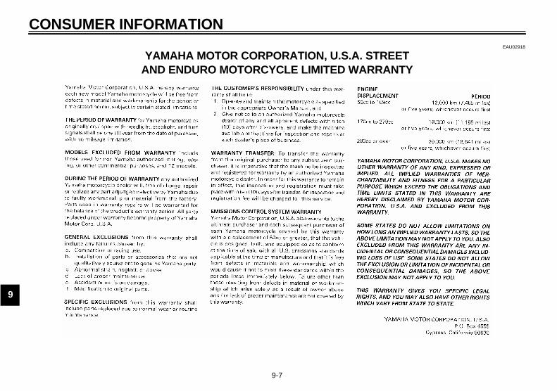
CONSUMER INFORMATION
9-7
9
EAU02918
YAMAHA MOTOR CORPORATION, U.S.A. STREET AND ENDURO MOTORCYCLE LIMITED WARRANTY

CONSUMER INFORMATION
9-8
9

CONSUMER INFORMATION
9-9
9
EAU01063
YAMAHA EXTENDED SERVICE (Y.E.S.)

CONSUMER INFORMATION
9-10
9

INDEX
AAccessories and replacement parts .......6-23Air filter elements, replacing ...................6-13
BBattery ...................................................6-35Brake and clutch levers, checking and
lubricating ............................................6-32Brake and shift pedals, checking and
lubricating ............................................6-31Brake fluid, changing .............................6-28Brake fluid level, checking......................6-27Brake lever...............................................3-8Brake lever free play, adjusting ..............6-24Brake light switch (rear), adjusting .........6-25Brake pads, checking.............................6-26Brake pedal..............................................3-8Brake pedal position, adjusting ..............6-25
CCables, checking and lubricating............6-31Canister (for California only).....................6-8Care.........................................................7-1Clutch lever..............................................3-7Clutch lever free play, adjusting .............6-23
DDimmer switch .........................................3-6Drive belt slack ......................................6-29
Adjusting ..........................................6-29Checking ..........................................6-29
EEngine break-in ....................................... 5-5Engine oil and oil filter cartridge ............... 6-9Engine stop switch................................... 3-7Engine trouble warning light .................... 3-3
FFront fork, adjusting............................... 3-12Front fork, checking ............................... 6-33Fuel ......................................................... 3-9Fuel level warning light ............................ 3-2Fuel tank cap........................................... 3-9Fuses, replacing .................................... 6-37
HHandlebar switches ................................. 3-6Headlight bulb, replacing ....................... 6-38Helmet holder ........................................ 3-11High beam indicator light ......................... 3-2Horn switch ............................................. 3-6
IIdentification numbers ............................. 9-1Ignition circuit cut-off system.................. 3-16Indicator and warning lights ..................... 3-2
KKey identification number ........................ 9-1
LLabels, location ....................................... 1-7License plate light bulb, replacing .......... 6-41
MMain switch/steering lock .........................3-1Maintenance and lubrication, periodic ......6-4Maintenance, emission control system.....6-3Maintenance, periodic ..............................6-1Maintenance record .................................9-5Model label ..............................................9-2
NNeutral indicator light ...............................3-3Noise regulation .......................................9-4
PParking.....................................................5-5Part locations ...........................................2-1Pre-operation check list............................4-1
RRear suspension, lubricating ..................6-33
SSafety defects, reporting ..........................9-3Safety information ....................................1-1Seat .......................................................3-11Shifting.....................................................5-3
Decelerating .......................................5-4Shift points..........................................5-4Starting out and accelerating ..............5-3
Shift pedal................................................3-7Shock absorber assembly, adjusting......3-13Sidestand...............................................3-15Sidestand, checking and lubricating .......6-33

INDEX
Spark plugs, checking ............................. 6-7Specifications .......................................... 8-1Speedometer........................................... 3-3Starting and warming up a cold engine.... 5-1Start switch.............................................. 3-7Steering, checking ................................. 6-34Storage.................................................... 7-4Supporting the motorcycle ..................... 6-42
TTachometer unit ...................................... 3-4Tail/brake light ....................................... 6-40Throttle cable free play, adjusting .......... 6-18Throttle grip and cable, checking and
lubricating............................................ 6-31Tires ...................................................... 6-19Tool kit..................................................... 6-2Transfer case oil .................................... 6-13Troubleshooting..................................... 6-42Troubleshooting chart ............................ 6-43Turn signal indicator lights ....................... 3-2Turn signal light bulb, replacing ............. 6-40Turn signal switch.................................... 3-6
VValve clearance, adjusting..................... 6-19Vehicle identification number ................... 9-1
WWarranty, extended ................................. 9-9Warranty limited....................................... 9-7Wheel bearings, checking...................... 6-35Wheels .................................................. 6-22


PRINTED IN JAPAN2002.07-0.5×2 CR
(E)
PRINTED ON RECYCLED PAPER YAMAHA MOTOR CO., LTD.


