Project Team Owner Contra Costa County Public Works Department Structural Engineer Arup, San Francisco Architect MacDonald Architects, San Francisco General Contractor Robert A. Bothman, Inc., San Jose, Calif. Steel Erector Adams & Smith Inc., Lindon, Utah Content provided by Arup, San Francisco Paul Mourraille Robert I. Schroder Pedestrian Overcrossing Walnut Creek, Calif. № 2 Case Studies in Structural Steel Crossing a major traffic intersection, the bridge is the centerpiece of a transit village. A seamless process from designer, contractor, fabricator, and erector achieved the complex geometry.
Transcript
Project Team
OwnerContra Costa County Public Works Department
Structural EngineerArup, San Francisco
ArchitectMacDonald Architects, San Francisco
General ContractorRobert A. Bothman, Inc., San Jose, Calif.
Steel ErectorAdams & Smith Inc., Lindon, Utah
Content provided by Arup, San Francisco
Paul M
ourraille
Robert I. Schroder Pedestrian Overcrossing Walnut Creek, Calif.
№ 2Case Studies in Structural Steel
Crossing a major traffic intersection, the bridge is the centerpiece of a transit village. A seamless process from designer, contractor, fabricator, and erector achieved the complex geometry.
Building Facts
Length of largest span: 245.0 ftTotal length: 630.0 ftDeck width: 10.0 ftSteel Tonnage: 230
Glenn Flem
ming
Each arch rib was fabricated in two segments that could be transported by road without special permit load restrictions. Pairs of half-ribs were temporarily tied together and erected with two cranes.
The bridge alignment was carefully woven through the site to preserve existing trees, especially a row of heritage oak trees that lined the original railroad right-of-way that was turned into a modern recreational trail.
Aru
p
Your connection toideas + answers
There's always a solution in steel.
American Institute of Steel ConstructionOne East Wacker Drive, Suite 700Chicago, IL 60601312.670.2400 www.aisc.org
Item 124.v2
Bridge Structure:The bridge serves as a focal point for a new transit-oriented development and presents an elegant solution to a particularly stringent set of constraints. A hands-on community design process identified a nearby 100 year-old through-truss bridge as a source of inspiration, which was reinterpreted in modern steel technology using digital design tools, high-strength steel, and digital fabrication techniques. The site, on the other hand, presented challenging constraints and interesting opportunities with respect to underground utilities and the existing trees. The resulting bridge is a visually dynamic and lightweight structure that springs from the ground to safely carry pedestrians and cyclists over the busy boulevard below. The bridge structure is over 630 ft long, with a main span of 245 ft and a 10-ft-wide path of travel. The main span is supported with cable hangers from two independent steel arch ribs. The arch ribs are supported on a single pile foundation that minimizes the foundation width, and they each incline away from the deck. This unique geometry, further accentuated by the curvature of the deck, creates a striking sculptural effect.
Principal Steel Shape: Hollow Structural Sections (HSS)Elevation: 136 ft above sea levelConstruction Cost: $6.8 million
Lightweight S-Shape Arch Bridge Design Reduces Steel Tonnage while Adapting to Complex Site ConstraintsThe adaptability of structural steel helps designers create a sleek and modern bridge that provides safe passage for pedestrians while avoiding cherished trees and an abundance of underground obstacles.
№ 2Case Studies in Structural Steel
Providing safe passage for pedestri-ans and bicyclists over a major traffic intersection in Walnut Creek, Calif., the new Robert I. Schroder Over-crossing is a vital link to a commuter railway station and a high-density residential and commercial develop-ment, serving both commuters ap-proaching the station and recreational users of the 33-mile-long Iron Horse Trail, of which it is a part.
The bridge structure is over 800 ft long, with a main span of 240 ft and a 10-ft-wide path of travel. The main span is supported with cable hangers from two independent steel arch ribs. The arch ribs are supported on a single pile foundation that mini-mizes the foundation width, and they
each incline away from the deck. This unique geometry, further accentuated by the curvature of the deck, creates a striking sculptural effect.
The bridge’s design curves to accommodate the surrounding elements. To avoid hitting the trees and utilities, the design team twisted the bridge’s body into an elongated S-shape. To take up as little surface space as possible, the structure relies on an unusual support system. The arches on either side emerge from a single common point at ground level, then tilt away from one another at approximately 20 degrees as they rise, leaving room in the middle for the bridge deck to rest. As a result, the support infrastructure underneath
takes only about half the space of a typical foundation.
The most visible structural sup-port, the double arches, comprise welded groupings of three 10-in.-diameter Hollow Structural Section (HSS) members, which are joined by steel plate stiffeners at 14-ft inter-vals and bent continuously to form curves. The two ground-level support structures consist of three slim con-crete pillars, two of which are tilted to the angle of the arches.
There was no need for arch bracing above the deck. Instead, a steel beam linking the two pairs of inclined buttress columns under the deck ensures adequate structural support.
The finished bridge has a clear span of 245 feet for the deck and the two independent arch ribs. Its dynamic structural form is generated directly from the resolution of the physical constraints of the site and is faithful to the community’s preferences.
Arup
The deck acts as a continuous beam running throughout the bridge, suspended from the arches by struc-tural hangers. It requires only about 2 feet of depth at its deepest point, ren-dering it considerably less bulky than most comparably sized bridge decks. This slender profile is enhanced by the curving underside, shaped to resemble the hull of a boat, a modification that also increases rigidity.
Regularly shaped ribs provide visual rhythm to the deck, making visible the structural action of the hangers supporting it. The push to craft a lightweight, minimal design with no superfluous elements significantly reduced the amount of steel used in the bridge. The total count was only 230 tons, or an average of 66 lbs per square foot, of deck plan across the entire structure—a very small figure compared to most bridges of this type.
Arup
The structure geometry of the bridge was very complex. The latest 3D modeling techniques were used to ensure clearances and critical dimensions were correct, and to anticipate and resolve constructability issues that could later cause delays and cost overruns.
An important site consideration was the presence of a multitude of underground utilities. This led the designers to the use of single pile-shaft foundations at each support, including the arches, which splay out at an angle from this narrow foundation.
Arup used a proprietary software analysis of the response of the bridge to pedestrian footfall excitation to verify that the design would be within acceptable limits for user comfort consideration, a subject in bridge design that has become increasingly important. Field measurements of the completed structure later confirmed the analytical results and the suitability of the design.
Arup
Arup
Arup
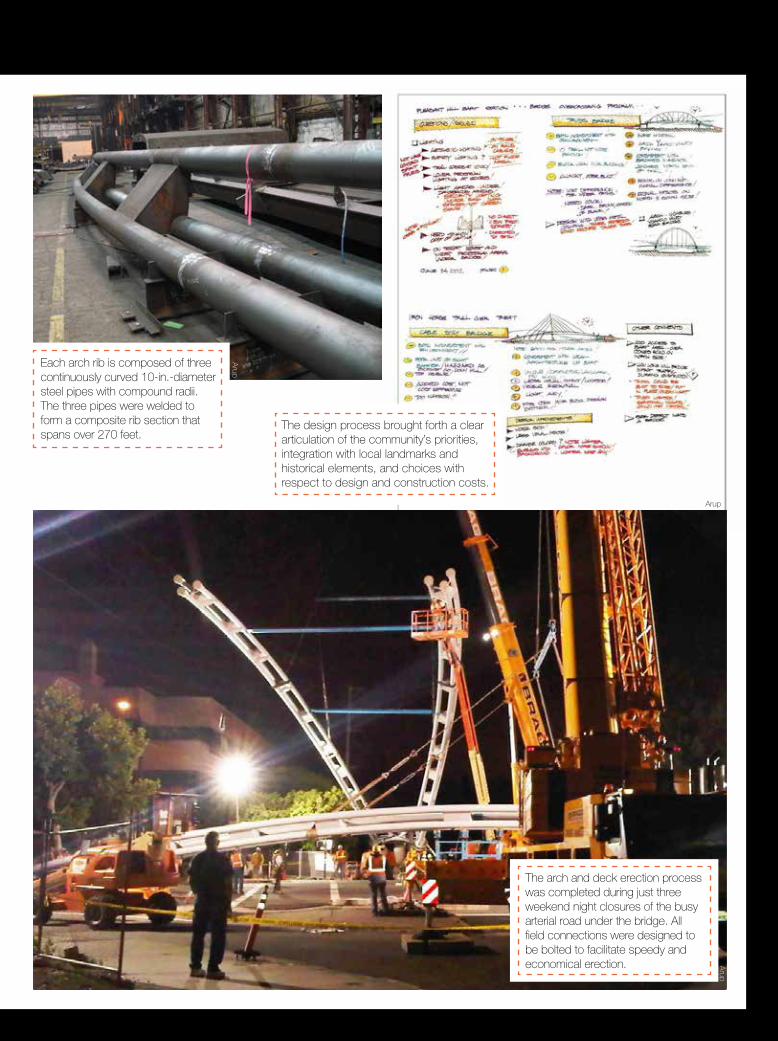
The design process brought forth a clear articulation of the community’s priorities, integration with local landmarks and historical elements, and choices with respect to design and construction costs.
The arch and deck erection process was completed during just three weekend night closures of the busy arterial road under the bridge. All field connections were designed to be bolted to facilitate speedy and economical erection.
Each arch rib is composed of three continuously curved 10-in.-diameter steel pipes with compound radii. The three pipes were welded to form a composite rib section that spans over 270 feet.
Arup
Arup
Building Facts
Length of largest span: 245.0 ftTotal length: 630.0 ftDeck width: 10.0 ftSteel Tonnage: 230
Glenn Flem
ming
Each arch rib was fabricated in two segments that could be transported by road without special permit load restrictions. Pairs of half-ribs were temporarily tied together and erected with two cranes.
The bridge alignment was carefully woven through the site to preserve existing trees, especially a row of heritage oak trees that lined the original railroad right-of-way that was turned into a modern recreational trail.
Aru
p
Bridge Structure:The bridge serves as a focal point for a new transit-oriented development and presents an elegant solution to a particularly stringent set of constraints. A hands-on community design process identified a nearby 100 year-old through-truss bridge as a source of inspiration, which was reinterpreted in modern steel technology using digital design tools, high-strength steel, and digital fabrication techniques. The site, on the other hand, presented challenging constraints and interesting opportunities with respect to underground utilities and the existing trees. The resulting bridge is a visually dynamic and lightweight structure that springs from the ground to safely carry pedestrians and cyclists over the busy boulevard below. The bridge structure is over 630 ft long, with a main span of 245 ft and a 10-ft-wide path of travel. The main span is supported with cable hangers from two independent steel arch ribs. The arch ribs are supported on a single pile foundation that minimizes the foundation width, and they each incline away from the deck. This unique geometry, further accentuated by the curvature of the deck, creates a striking sculptural effect.
Principal Steel Shape: Hollow Structural Sections (HSS)Elevation: 136 ft above sea levelConstruction Cost: $6.8 million
Your connection toideas + answers
There's always a solution in steel.
American Institute of Steel ConstructionOne East Wacker Drive, Suite 700Chicago, IL 60601312.670.2400 www.aisc.org