59
ROBONICS’ 15 Powered By:
| Date post: | 29-Dec-2015 |
| Category: |
Documents |
| Upload: | jeremy-burns |
| View: | 213 times |
| Download: | 0 times |

ROBONICS’ 15
Powered By:

An embedded system is some combination of computer hardware and software, either fixed in capability or
programmable, that is specifically designed for a particular function.
EMBEDDED SYSTEM

APPLICATIONS
Aerospace
Navigation systems, automatic landing systems, flight attitude controls, engine controls, space
exploration (e.g.. The mars pathfinder)

APPLICATIONS
Automotive
Fuel injection control, passenger environmental controls, anti-locking braking systems, air bag
controls, GPS mapping.

APPLICATIONS
Communications
Satellites, network routers, switches, hubs

APPLICATIONS
Medical
CT, One touch glucose meter, almost all medical facility.

APPLICATIONS
Personal
Pagers, cell phones, video games, I-pod, MP3 players

APPLICATIONS
Home
Dishwashers, microwave ovens, VCR’s, DVD, televisions, stereos, fire/security alarm systems,
lawn sprinkler controls, thermostats, digital cameras, clock radios, cell phones

Features/Components
Central Processing Unit and Software
Memory: ROM , RAM , EEPROM , Flash
Input: Buttons, knobs, probes , sensors.
Output: LCD Display , SSD , Matrix Display

MICROCONTROLLER
A microcontroller (sometimes abbreviated µC, uC or MCU) is a small computer on a single integrated circuit containing a processor core,
memory, and programmable input/output peripherals. Program memory in the form of NOR flash is also often included on chip, as
well as a typically small amount of RAM. Microcontrollers are designed for embedded applications, in contrast to the
microprocessors used in personal computers or other general purpose applications.
What Wikipedia says……

Microcontrollers are programmable single chip computers specifically designed to:
• Read input devices, such as buttons and sensors• Process data or information• Control devices, such as lights, displays, motors and speakers• Have on-chip Peripherals
Formal Definition

Different Microcontrollers
• Intel
• Motorolla
• Microchip
• Atmel
• STMicroelectronics
• Texas Instruments
•NXP
•Toshiba
•Freecscale

ATmega
Atmel Microcontrollers
ATtiny
ATxmega
o Atmega 8o Atmega 16o Atmega 32o Atmega 328o Atmega 644 etc

ATMEGA 16 : AN OVERVIEW
• 8-bit Micro-controller
• 40-pin DIP
• 32 Programmable I/O Lines
• Operating Voltages 2.7 - 5.5V
• Speed Grades 0 - 8 MHz
• 16K Bytes of In-System Self-programmable Flash program memory 512 Bytes EEPROM
• Two 8-bit Timer/Counters with Separate Prescalers and Compare Modes
• One 16-bit Timer/Counter with Separate Prescaler, Compare Mode, and 8-channel, 10-bit ADC
• Programmable Serial USART
• Master/Slave SPI Serial Interface
• I2C interface

Pin Diagram

Architecture

Simplified Diagram

Personal Computer Microcontroller
• uP• RAM•HDD• Clock• Ports (Serial/USB)• Ports (Parallel)• Mic /Headphone Jack (ADC/ DAC)• Power Supply Unit (SMPS)• Reset Button• Mother-board
• uP• SRAM• EEPROM & Flash Memory• Clock Unit• SPI / UART Controllers• Digital I/O Ports• ADC • Power Supply Unit• Reset Pin• IC

MICROCONTROLLER PROGRAMMING
• Machine Language Programming• Assembly Language Programming• High Level Language

Machine Language Programming
Code in binary instructions form that is directly executed by the device.
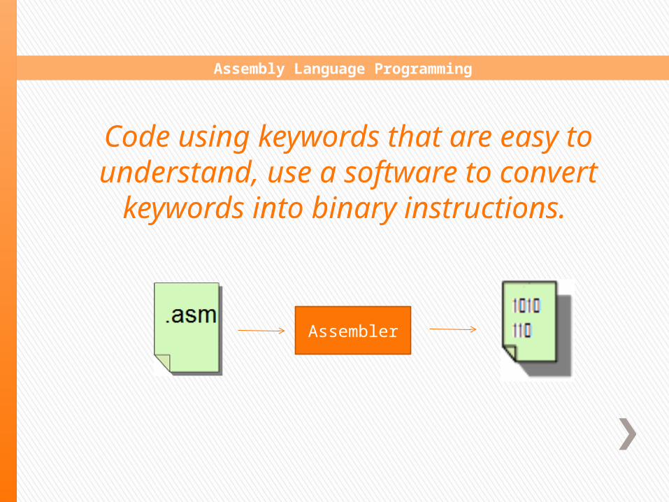
Assembly Language Programming
Assembler
Code using keywords that are easy to understand, use a software to convert
keywords into binary instructions.

High Level Programming
Compiler & Linker
OS
Code in symbolic form, use a software to break symbolic instructions into actual instructions of uC

We will use the High Level programming language for driving and exploiting the capabilities of our
microcontroller.

WinAVR Cross-Compiler & linker
PC / Laptop
Target System (Atmega R&D Board)
OUR PROGRAMMING ENVIRONMENT

PORT PROGRAMMIMG
Normal C program
int x;float y;
x= 10;y= 8.97;
Program for Ports
DDRA = 0b11111111 or 0xFF // o/pDDRC = 0b11111111 or 0xFF // o/p
PORTA = 27; // decimalPORTC= 0b11010110; // binary
DDRx defines whether the port will act as input port or o/p port. Just as ‘int’ declares a variable as integer type. It does not assign any value to it.
PORTx assigns the value to be output. If DDRx=0 i.e port is defined as input port, PORTx will store the value but will not o/p it.

More Examples
PORTA=0x5A ;PORTA=0b01011010;PORTA=5;
DDRA=0xFF;DDRA=0b11110000; // pins A7-A4 as o/p & A3-A0 as i/p
You can even address individual pins of any PortDDRA.3= 1; // Only Pin 3 of Port A (A4) is configured as o/p pin , rest untouched
PORTA.0=1; // pin 0 of Port A outputs 1, rest retain there previous values

Taking Input
To take Digital i/p from external world first configure the port as i/p port using DDRx=0
Use PINx to read the digital value.
x = PINA // read 8 bit integer value from Port A. 0 < x < 255y= PINB
x, y must be defined as unsigned integers in ur C program.
Individual pins can be read in the same way.
x= PINA.2 // as the individual pins are read n the value is digital, therefore x can either be 0 or 1
y= PINC.6

CHOCOLATE QUESTION
Write a program to o/p 33 (hex) on PortD and read pins 2 and 7 of Port A

#include <avr/io.h>#include <util/delay.h>
void main( ){unsigned int x,y;
DDRD=0xFF; // all pins o/pDDRA=0b01111011; // pin 7 & 2 i/p rest immaterial
PORTD=0x33;x=PINA.2;y=PINA.7;}
Solution

Creating the programming environment in WinAVR

Create a folder ‘Demo’ on desktop

Go to start Menu. Select WinAVR and click on Mfile

Mfile window will appear Go to ‘File’ and click on ‘Save As’

Save the mfile in the folder ‘Demo’ created on desktop. Name of the file should be ‘Makefile’ .

Go to start Menu again. Select WinAVR and click on ‘Programmers notepad ‘

Programmers notepad window will appear

Go to File menu and click on ‘Save As’.

Save the file naming it as ‘main.c’ in the Demo folder created on desktop.

Go to ‘Programmers Notepad’ again and click on ‘Open’

Select the ‘Makefile’ and open it.

We have to make certain changes in the Makefile. MCU= atmega16

We have to make certain changes in the Makefile. F_CPU= 8000000 TARGET= main

We have to make certain changes in the Makefile. AVRDUDE_PROGRAMMER = usbasp AVRDUDE_PORT = usb001

Include the basic header files and create the main function.

Go to ‘Tools’ menu and click on ‘Make All’ . Check if there is any error or not at output window

Go to ‘Tools’ menu and click on ‘Program’ in order to burn your code in the microcontroller

RESEARCH & DEVELOPMENT (R&D) BOARDS
R & D Boards are used for the rapid prototyping of the Embedded Systems

Serial Port
ADC Port
LCD Port
+5V
GND
Motor Port
Motor Driver
Supply
IC 7805
Reset Button

LCD Port
ADC PortMotor Port
Power Button
IC 7805
Reset Button
Adapter Buzzer

LED BLINKING
HELLO! TO EMBEDDED WORLD

+
- GND
+ V
Longer leg is positive Terminal
Light Emitting Diode
A light emitting diode is essentially a PN junction that emits a
monochromatic light when operated in forward bias

LED connection to Atmega
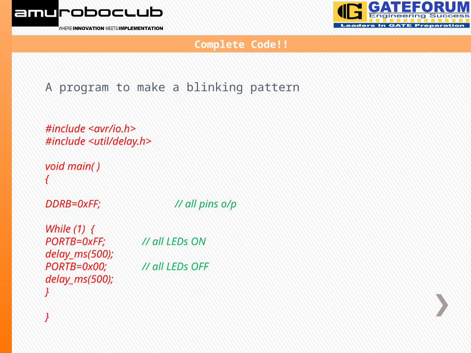
A program to make a blinking pattern
#include <avr/io.h>#include <util/delay.h>
void main( ){
DDRB=0xFF; // all pins o/p
While (1) {PORTB=0xFF; // all LEDs ONdelay_ms(500);PORTB=0x00; // all LEDs OFFdelay_ms(500);}
}
Complete Code!!

LIQUID CRYSTAL DISPLAY
LCD (Liquid Crystal Display) screen is an electronic display module and find a wide range of applications. A 16x2 LCD display is very basic module and is very commonly used in various devices and circuits.

PIN DIAGRAM

PIN DESCRIPTION

Two modes are there in LCD.• 8 BIT MODE: In this mode of operation of LCD, data
flows on 8 bit data bus.• 4BIT MODE: In this mode of operation of LCD, data
flows on 4 bit data bus.
MODES OF LCD

LCD DEMO
PRINT YOUR NAME ON LCD!!

Contact Us:
www.amuroboclub.inwww.amu.ac.in/rclub.jsp
fb.com/amuroboculb


