53
Robosoccer 2009-Shaastra 2008 Aditya Shankar Anirudh Sivaraman Anubhav G Bhattacharjee Ashwin Ramesh Gaikwad Ashwin Ram Suresh Raghunandan S Shankar Ganesh July 25,2008 1

Robosoccer 2009-Shaastra 2008
Aditya ShankarAnirudh Sivaraman
Anubhav G BhattacharjeeAshwin Ramesh Gaikwad
Ashwin Ram SureshRaghunandan SShankar Ganesh
July 25,2008
1

Contents
1 Why are we doing this? 5
2 Communication Module 62.1 Role of Communication Module : . . . . . . . . . . . . . . . . . 62.2 Requirements / Objectives: . . . . . . . . . . . . . . . . . . . . 62.3 Choices Available: . . . . . . . . . . . . . . . . . . . . . . . 82.4 How well they meet the requirements: . . . . . . . . . . . . . . . 9
2.4.1 Sparkfun Wireless module . . . . . . . . . . . . . . . . . 92.4.2 Radiometrix Modules : . . . . . . . . . . . . . . . . . . . 92.4.3 Wi-Fi . . . . . . . . . . . . . . . . . . . . . . . . . . . 102.4.4 TI boards . . . . . . . . . . . . . . . . . . . . . . . . . 10
2.5 Our Plan of Action : . . . . . . . . . . . . . . . . . . . . . . . . 102.6 Encoding . . . . . . . . . . . . . . . . . . . . . . . . . . . . . . 10
2.6.1 Encoding for Balancing: . . . . . . . . . . . . . . . . . . 102.6.2 Encoding for Error detection/correction : . . . . . . . . . 11
2.7 Input/Output : . . . . . . . . . . . . . . . . . . . . . . . . . . . 112.7.1 Input : . . . . . . . . . . . . . . . . . . . . . . . . . . . 112.7.2 Output : . . . . . . . . . . . . . . . . . . . . . . . . . . 11
2.8 Work done : . . . . . . . . . . . . . . . . . . . . . . . . . . . 112.9 Work to be done : . . . . . . . . . . . . . . . . . . . . . . . . . 122.10 Budget : . . . . . . . . . . . . . . . . . . . . . . . . . . . . . . 13
3 Image Processing Module : 143.1 Work Done So Far: . . . . . . . . . . . . . . . . . . . . . . . 143.2 Task at Hand: . . . . . . . . . . . . . . . . . . . . . . . . . . . 143.3 Requirements: . . . . . . . . . . . . . . . . . . . . . . . . . . . 143.4 Programming methodology . . . . . . . . . . . . . . . . . . . . 153.5 References : . . . . . . . . . . . . . . . . . . . . . . . . . . . . 153.6 Arena Details: . . . . . . . . . . . . . . . . . . . . . . . . . . . 15
4 AI Module 174.1 An Overview . . . . . . . . . . . . . . . . . . . . . . . . . . . . . 174.2 The Model . . . . . . . . . . . . . . . . . . . . . . . . . . . . . . 174.3 The Input and Output: . . . . . . . . . . . . . . . . . . . . . . 174.4 Interface with the robots: . . . . . . . . . . . . . . . . . . . . . 174.5 The Programming Methodology: . . . . . . . . . . . . . . . . . 18
4.5.1 Level 0 . . . . . . . . . . . . . . . . . . . . . . . . . . . 194.5.2 Level 1 . . . . . . . . . . . . . . . . . . . . . . . . . . 194.5.3 What is Active potential method? . . . . . . . . . . . . . 20
2
4.5.4 Level 2 . . . . . . . . . . . . . . . . . . . . . . . . . . 204.5.5 Level 3 . . . . . . . . . . . . . . . . . . . . . . . . . . 20
4.6 The method used to carry out the decisions . . . . . . . . . . . . 204.6.1 Other Miscellaneous Code required . . . . . . . . . . . . 21
4.7 The basic framework . . . . . . . . . . . . . . . . . . . . . . . . 224.7.1 Enums: . . . . . . . . . . . . . . . . . . . . . . . . . . . 224.7.2 Classes: . . . . . . . . . . . . . . . . . . . . . . . . . . . 22
4.8 A Need to test and tweak . . . . . . . . . . . . . . . . . . . 254.9 Why we need Webots . . . . . . . . . . . . . . . . . . . . . . 26
5 Mechanical Design: 275.1 Statement of Goals and Objectives: . . . . . . . . . . . . . . . . 275.2 Objectives to achieve: . . . . . . . . . . . . . . . . . . . . . . 275.3 Design: . . . . . . . . . . . . . . . . . . . . . . . . . . . . . . . 275.4 Drive system objectives . . . . . . . . . . . . . . . . . . . . . . 285.5 Driving Systems: . . . . . . . . . . . . . . . . . . . . . . . . . . 285.6 Omni-wheel design . . . . . . . . . . . . . . . . . . . . . . . . . 285.7 Components of drive system . . . . . . . . . . . . . . . . . . . . 30
5.7.1 Motors . . . . . . . . . . . . . . . . . . . . . . . . . . . 305.7.2 Trans-wheels . . . . . . . . . . . . . . . . . . . . . . . . 32
5.8 Kicking Mechanisms . . . . . . . . . . . . . . . . . . . . . . . . 325.8.1 Ideas/mechanisms considered for the kicking mechanisms 33
5.9 Dribbler mechanisms: . . . . . . . . . . . . . . . . . . . . . . . 345.9.1 Components and Design Implementation . . . . . . . . . 34
5.10 Overall component requirements: . . . . . . . . . . . . . . . . . 365.10.1 Drive Motors: . . . . . . . . . . . . . . . . . . . . . . . 365.10.2 Solenoids: . . . . . . . . . . . . . . . . . . . . . . . . . 385.10.3 Trans-wheels: . . . . . . . . . . . . . . . . . . . . . . . 415.10.4 Dribbler motors: . . . . . . . . . . . . . . . . . . . . . . 41
5.11 Weight estimates for various components: . . . . . . . . . . . . . 415.12 Progress till now: . . . . . . . . . . . . . . . . . . . . . . . . . . 435.13 Overall budget requirements . . . . . . . . . . . . . . . . . . . . 43
6 Electrical Design 446.1 Primary Objectives: . . . . . . . . . . . . . . . . . . . . . . . . 446.2 Block diagram of the electrical system: . . . . . . . . . . . . . . 456.3 Description of the subsystems in the block diagram: . . . . . . . 45
6.3.1 Motion (drive) system: . . . . . . . . . . . . . . . . . . . 456.3.2 Communication interface: . . . . . . . . . . . . . . . . . 456.3.3 Dribbler interface: . . . . . . . . . . . . . . . . . . . . . 47
6.4 Hardware selection for the electrical subsystems: . . . . . . . . . 47
3

6.4.1 Motion Control: . . . . . . . . . . . . . . . . . . . . . . 476.4.2 Micro controller/processor: . . . . . . . . . . . . . . . . 486.4.3 Micro controller comparison: . . . . . . . . . . . . . . . . 496.4.4 Selection criteria: . . . . . . . . . . . . . . . . . . . . . 49
6.5 Motor Controllers: . . . . . . . . . . . . . . . . . . . . . . . . . 506.6 Batteries: . . . . . . . . . . . . . . . . . . . . . . . . . . . . . . 506.7 List of components required: . . . . . . . . . . . . . . . . . . . . 50
4

1 Why are we doing this?
Robotics by itself is a multidisciplinary field with Computer Science, Electronics,and Mechanical Engineering coming together to make an automated productthat can work wonders. The interdisciplinary nature of work presents us withnew challenges when it comes to integrating the various modules. Robosoccer isno exception to this fact. The transition from theory to practice is an invaluableone and this endeavour will give us a chance to apply the engineering we knowto solve a fairly challenging problem: that of getting five robots to play soccerin a coordinated manner. This involves ideas and theories from design, controlsystems, hardware programming, AI, Image Processing and Wireless communi-cation. Being a team project, it would give us a flavour for how large scaleengineering projects work. It would also serve as an exposure for most of us tofields apart from our core specialisation.The aim of Robocup is stated as follows:
The RoboCup Initiative is an international research group whose aims are topromote the fields of Robotics and Artificial Intelligence. Through the integrationof technology and advanced computer algorithms, the goal of RoboCup is to builda team of humanoid robots that can beat the current World Cup champions bythe year 2050.
5
2 Communication Module
2.1 Role of Communication Module :
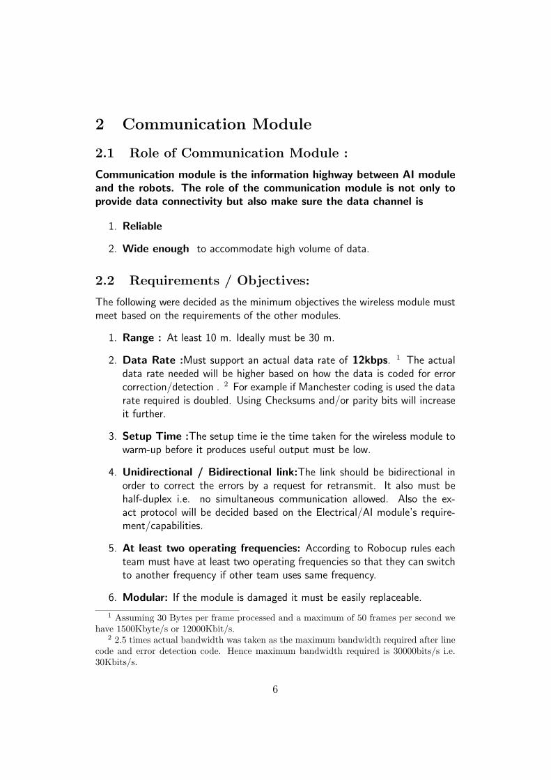
Communication module is the information highway between AI moduleand the robots. The role of the communication module is not only toprovide data connectivity but also make sure the data channel is
1. Reliable
2. Wide enough to accommodate high volume of data.
2.2 Requirements / Objectives:
The following were decided as the minimum objectives the wireless module mustmeet based on the requirements of the other modules.
1. Range : At least 10 m. Ideally must be 30 m.
2. Data Rate :Must support an actual data rate of 12kbps. 1 The actualdata rate needed will be higher based on how the data is coded for errorcorrection/detection . 2 For example if Manchester coding is used the datarate required is doubled. Using Checksums and/or parity bits will increaseit further.
3. Setup Time :The setup time ie the time taken for the wireless module towarm-up before it produces useful output must be low.
4. Unidirectional / Bidirectional link:The link should be bidirectional inorder to correct the errors by a request for retransmit. It also must behalf-duplex i.e. no simultaneous communication allowed. Also the ex-act protocol will be decided based on the Electrical/AI module’s require-ment/capabilities.
5. At least two operating frequencies: According to Robocup rules eachteam must have at least two operating frequencies so that they can switchto another frequency if other team uses same frequency.
6. Modular: If the module is damaged it must be easily replaceable.
1 Assuming 30 Bytes per frame processed and a maximum of 50 frames per second wehave 1500Kbyte/s or 12000Kbit/s.
2 2.5 times actual bandwidth was taken as the maximum bandwidth required after linecode and error detection code. Hence maximum bandwidth required is 30000bits/s i.e.30Kbits/s.
6

Figure 1: System Block Diagram:
7

7. Simple Interface: The module must provide a simple interface to bothelectrical and AI teams i.e. they must be able to treat it as a simpleinput/output element. Also the interface must be serial so that it doesnteat up too many pins in the micro controller and directly interfaced with+5V logic in micro controller.
8. Scalability: The next years team must continue our work and improveupon it rather than starting from scratch. Hence our module must beeasily scalable for higher performances in future.
2.3 Choices Available:
Based on the above criteria we came up with the following list of modules.
1. Sparkfun Wireless Module(433MHz/314MHz)
2. Radiometrix Modules
3. UHF Radio Packet Controller(UHF-RPC)
4. Tx2/Rx2 Modules
5. Tx3/Rx3 Modules
6. TxL2/RxL2 Modems
7. UHF Radio Packet Modem(UHF-RPM)
8. Other modules like BiM modules were considered but didnt meet our re-quirements.
9. In addition to these Radio Packet modules, we also considered well es-tablished and standardized protocols such as Wi-Fi under Prof. BhaskarRamamurthy’s advice.
10. Ready made modules from Texas Instruments ( ie the EZ430-RF25002.5 Ghz transceiver) have also been considered since free samples areavailable for testing. These are based on TI’s proprietary protocols.
8

[][]
Table 1: SparkFun specsParameter SpecificationsFrequency 433 MHz/314MHz
Range ≥ 100mType Transmitter/Receiver modules separate.
Data Rate 4800bits/sSetup Time N/A
Interface Serial
2.4 How well they meet the requirements:
2.4.1 Sparkfun Wireless module
Advantage :Easily available(in Chennai) and easy to implement. Small size.Disadvantage:Data rate is too low. Reliability is a problem.Conclusion : This can be used as a test bed for our experiments since itis not very costly or complicated. But it doesnt satisfy our requirements.
2.4.2 Radiometrix Modules :
The Radiometrix modules specifications are tabulated in a table for ease of com-parison. All of them have more than 50 m range.
[]
Table 2: Radiometrix ModulesParameter UHF-RPC Tx2/Rx2 Tx3/Rx3Frequency 418/433 MHz 418/433 MHz 869/914 MHzData Rate 64kbps 160kbps 64kbps
Setup Time 5 ms ≤ 2ms ≤ 2 msInterface Parallel Serial Serial
The UHF-RPC was rejected because of its high setup time and par-allel interface. From the remaining two modules Tx2/Rx2 is selectedbecause of its higher data rate and also Tx3/Rx3 didnt offer any signif-icant advantage over Tx2/Rx2. Further advantage of Tx2/Rx2 includesmall size(footprint), and low power consumption.
9

2.4.3 Wi-Fi
The primary advantage of Wi-Fi over other modules is greater reliability . Wi-Ficomes in built with enough error checks and guarantees error free transmis-sion and is well above our required data rates. It is also a relatively cheap optionwith easy availability of Wi-Fi cards. However, writing drivers is a fairly involvedtask.
2.4.4 TI boards
These boards support data rates far exceeding our requirements and are easilyprogrammable under a USB interface. The only disadvantage they might haveis that they are restricted to a single frequency.
2.5 Our Plan of Action :
1. Sparkfun modules ( some are available from TRI India) will be used as ourtest bed initially to test our basic routines.
2. If we do manage to procure free samples from TI, we will test these outtoo.
3. We shall evaluate the complexity of using Wi-Fi as a means of communi-cation.
4. Radiometrix Tx2/Rx2 Modules will also be tested.
5. Based on initial results, we will select the method that works best. Thismodule would then be integrated with the rest of the modules.
2.6 Encoding
(applies only in the case of using Radiometrix and Sparkfun modules):
2.6.1 Encoding for Balancing:
To prevent the small changes in frequency/noise from affecting the transmissionwe use line codes. These codes are used to ensure there is always a maximumof only so many ones or zeros in the signal continuously. This is done so thatthe receiver can synchronize its clock with the transmitters clock whenever atransition from 1 to 0 or 0 to 1 takes place. We will be using Manchester codingwhich is the simplest of the Line codes to implement.
10

2.6.2 Encoding for Error detection/correction :
To know if the data received at the receiver is correct usually a few more bitsat the end called check bits are added. Usually increase in error detection ca-pability comes with a corresponding increase in size of check bits required thusmaking data bulkier. Processing is required for detecting the error and if possiblecorrecting it(which consumes precious microprocessor resource).Thus a balancemust be found between error detection capabilities and resources consumed. Asof now the following error detection codes have been considered.
1. Hamming code.
2. Parity check.
3. Checksum
4. Cyclic Redundancy codes.
The exact encoding is to be determined based on further research.
2.7 Input/Output :
2.7.1 Input :
As mentioned in AI team document the input to the Communication module willbe a set of bytes from their C/C++ files to be transmitted to the robot.
2.7.2 Output :
The output of this module will be the same set of bytes given by AI team but tothe on- board electronics on the robot.
2.8 Work done :
1. Studying different modules available and selection of suitable modules.
2. Testing codes for communication between computer and RF module andRF module and micro controller.
3. Successfully operating the USART on the micro controller using an RS 232connection. The USART is the micro controller’s communication utility.
11

2.9 Work to be done :
1. Testing of both the Sparkfun and Radiometrix modules .
2. Further studies on encoding schemes ( required if we need to do the errorcoding ourselves).
3. Evaluating the TI Z430-RF2500 and studying if a Wi-Fi based solution isfeasible.
4. Coding for transmitting code to microcontroller (for any of the aboveschemes). (This code has already been tested through a direct link ona microcontroller. Further testing involves the addition of RF module in-stead of the direct link.)
12

2.10 Budget :
[]
Table 3: Communication budgetItem No. of units and Cost per unit Total Cost
Sparkfun modules 5*500 Rs Rs 2500Radiometrix modules(Tx2+Rx2) 6*13.8 USD 82.80 USD
Antennas 7*5.41 USD 37.29 USDShipping Charges 70.00 USD
Wi-Fi cards Rs 1000Miscellaneous Rs 1500
Customs@10 % of foreign purchases 19 USDTotal Rs 5000+ 209 USD
Rs 14000.
13

3 Image Processing Module :
3.1 Work Done So Far:
A basic code that detects the camera connected to the computer, takes inputfrom the camera (a webcam for the time being) i.e. stream in the view captureddivide it into frames and perform the operations. Operations performed arebasically determining patches of pixels of same color. Thus we can detect thecoordinates, velocities and direction of motion of the Bot and that of the ball.This is all the input that the AI team needs to work on. We used a camerawith resolution 640*480 but being more primitive considering the requirementsfor Robocup we need advanced equipment. After searching the net and takingsuggestions from other teams abroad we’ve arrived at our requirements
3.2 Task at Hand:
1. To build the arena
2. To make the code work for the actual arena. The code must be robust tolighting changes and so on.
3. To study the methodology of usage of 2 cameras.
4. To choose the right camera.
3.3 Requirements:
From suggestions from other teams (through team documentation) and linkswe would be requiring two cameras for good results. In consultation with Prof.Mittal of the CS department, we found out that a minimum of 25 pixels isrequired to detect a feature reliably ( ie without capturing stray features). Thestandard camera resolution used in Robocup is 640*480; increasing this wouldmean slower processing. At this resolution, if we use just one camera for thewhole field (6 m by 4 m) we would get only 18 pixels to detect the ball. Hencewe need two cameras, one covering each half of the field with minimal overlap.In addition to the cameras a lens is required to extend the field of view. Wealso need a Firewire card reader to capture the images and send them to thecomputer.
Budget Estimate: We have contacted Lucid Imaging in Bangalore regardingthe procurement of cameras. They have found a camera fitting our specifications.We have been told that it will cost us Rs 63000 per camera ; they have thecameras in stock. Hence we do not incure much shipping or customs charge on
14

that front. The frame grabber card costs Rs 6000, and can accomodateboth cameras. The lens costs Rs 9000 per unit, and for two camerasthis amounts to Rs 18000. The lens needs to be imported. Hence thetotal budget, exclusive of some shipping charges for the lens, amountsto roughly 1.5 lakhs . However, we may be able to save a lot of moneyon this front since Prof. Mittal has been gracious to allow us the use ofthe Artificial Neural Networks Lab in the CS department. The lab hasIndustry level cameras designed for machine vision. At present though,we are using a Logitech Webcam that we procured locally.
3.4 Programming methodology
: OpenCV will be used as the software platform for us to develop our imageprocessing code. This is a free and open source C library of Image Processingfunctions provided by Intel. Our work so far has been implemented entirely onOpenCV. However, it was done under favourable conditions of good lighting.We need to incorporate camera calibration too due to imperfections in imagingand improve our algorithms so that they are more robust. After talking to Prof.Mittal, we have found out that background subtraction is the standard techniquefor such a problem. We are in consultation with the research scholars inthe ANN lab and have even managed to successfully implement onebackground subtraction technique.
3.5 References :
1. http://www.adept.net.au/grabbers/firewire.shtml
2. http://damien.douxchamps.net/ieee1394/cameras/
3. http://www.aegis-elec.com/products/firewire-cams.html
4. ftp://ftp.itam.mx/pub/alfredo/PAPERS/Weitzenfeld10691.pdf
5. http://www.cis.cornell.edu/boom/2005/ProjectArchive/robocup/documentation.php
3.6 Arena Details:
Using the details in the Robocup rules regarding the arena,The area of the Arena is - 342 sq ft. This is including the wood reqd.
for the walls and the goal posts. The wood is available at a store right nextto the NCC gate, to the right of the gate. The cost of various grades and sizes -
15

[]
Table 4: Cost of woodType Cost
Medium Grade -8 mm thickness 19 / sq ft.Medium Grade- 12 mm thickness 23/sqft
Best grade - 12 mm thickness 30/sqft
At Workshop we found out that the 8mm grade might be too thin, as its quitebendy. We also got to know that if sum machine work has to be done on thewood then best grade is more suited than medium .Transporting the wood here ( to the workshop ) - 100
Total Cost -8mm Med. Grade - 660012mm Med Grade - 800012mm Best Grade - 10360
Thus the arena construction would take around Rs 15000 takinginto account some labour charges and wastages too Hence the totalImage Processing budget, including the arena and customs for the lenscomes out to Rs 1.8 Lakhs
16
4 AI Module
4.1 An Overview . . .
The overall aim of this module is to act as a decision making servicewhich will make the robots act according to a dynamically chosen strat-egy.
4.2 The Model . . .
At present , we have opted for a deterministic model of actions (asopposed to a learning based approach which would need a lot of re-sources). We will probably shift to that approach after Shaastra sincelearning would need physical bots actually playing with the ball.
4.3 The Input and Output:
The image processed data containing the position of the ball, the bots and thegoal coordinates is supplied to the AI module as the input. Also input are,the direction and speed of the robots and the direction each robot is facing.The AI module decides the actions/ strategy to be adopted and sends it to thecommunication module. (which will decode the hardware instructions into bitstreams).
4.4 Interface with the robots:
A bit stream containing the relevant information regarding the motor rpm andwhether the kicker is to be triggered is sent at a baud rate of 12000 bits/second
The sequence of actions is roughly
1. Image process
2. Decide strategy
3. Send instructions
4. interpolate
5. Decide strategy
6. Send instructions
17

7. interpolate . . .. . .. . .. . .
8. Process next frame
. . . and so on With the image processing and AI both sharing the same processor,there is a significant probability that the AI module does not receive frames every1/30th of a second. Instead, it may be as low as 1/10th of a second. At a speedof 1 m/s, this means a probable error of 10 centimeters. So some amount ofinterpolation must be done. Which means, a prediction of the expected positionof the robots is done based on the commands issued, so that we have a morerecent image which may be used to issue the next command. Otherwise, we maynot be able to optimally issue commands in the interval between one processedframe and the next.This reiterates the importance of an accurate system so that the interpolationmodels reality as closely as possible. The importance of a powerful computercannot be overstated, since we will need to do (bold) image processing, AIprocessing and transmission of the instructions simultaneously (using threads).
4.5 The Programming Methodology:
The code is written in such a way that only one action is taken by agiven bot. These are the actions that are intimately connected to thehardware and are incidentally the commands that are sent to the robotsin the form of bit streams wirelessly.
This can be one of . . .
1. Move / Turn We control the speed of the three motors so that theresultant is in the direction required, it is of utmost importance that themotor rpm be very precise. Else, the bot will end up moving in a differentdirection than what is expected. This is transmitted using a string of bitssignifying the speed of each motor.
2. Kick The solenoid kicker is triggered so that it kicks the ball. This isconveyed by the simple existence or non-existence of a particular bit (sincethe kicker has just two states on and off)
The Code is written in layers
18

4.5.1 Level 0
The level above the hardware level described above. This consists of elementaryactions like
1. Hit to a particular location The robot first turns to face the location andthen kicks the ball.
2. Move to a particular location As long as the bot is not yet at the location,it keeps moving towards the location. (in a straight line)
3. Avoid an obstacle at a given location Assumes a radius for every obstacle.The bot corrects its path to go tangentially to the circle. (the circle ofinfluence)
4. Move Goalkeeper moves the goal key towards the expected position of theball depending on the direction the striker is facing.
All these functions are written so that, the robot does exactly one action percommunication interval. Also, the above instructions just start off the action.
In other words, suppose the aim is to move to a particular location, the botmoves towards the position desired.
4.5.2 Level 1
This level involves more complex actions such as
1. Passing the ball to another player it is to hit the ball towards the locationof the required player.
2. Move towards player Mainly to defend against attacks. The robot willmove to block the attacking robot by moving in front of the (solenoid)kicker.
3. Intercept ball To collect a moving ball. Basically moves towards thelocation of the ball.
4. Obstacle avoidance :Moving from any point to another involves the obstacledetection inbuilt. The algorithm used by most major teams around theworld is called Active potential method.
19

4.5.3 What is Active potential method?
Well, lets say we have 5 objects on the field. We have to avoid them when wemove since the robocup rules are pretty tough against tackling. To do this, weassign repulsive potentials to the obstacles and an attractive potential to thedestination. The attractive potential will stretch from the destination to therobot. The equations of these potentials are pretty much predefined. Then wefollow the potential gradient to the destination. This is done by a function thatwill return a velocity vector given the present positions of the other robots.
4.5.4 Level 2
This level is concerned with directions to a set of players (defense, attack orgoal keeper). For example, a command Defend would command the defendersto block the player with the ball , then second biggest threat and then the thirdand so on, depending on the number of defenders available. The threat levelswill be assigned based on the position of the opposing players
Similar actions will be done for attack also.
4.5.5 Level 3
This is the topmost level and is the decision making module that will assignactions to the robots. The decisions are taken based on the threat levels of theopposition players and the value of the robots in our team. In addition, we willalso use the weight assigned to each spot on the terrain. (more on this in thenext section). This section is like the coach.
4.6 The method used to carry out the decisions
Finite State Machine: It is a model of behavior composed of a finite number ofstates, transitions between those states, and action. They are used for determin-istic decision making. This is what a simple FSM looks like:
So, at every state, the model says what should happen if the state changes.The above would be in case of an attacking bot. Pressing means that the botwill put pressure on the opponent. For example in the above, if the bot currentlyis moving to the ball and it gets the ball, it dribbles. When it is dribbling , itcontinuously searching for opportunities to pass or shoot. After it makes theshot, it goes into a NULL state, which is again updated every cycle by the level3 functions. Whereas if it loses the ball when it was dribbling, it goes into statePRESSING if an unmarked bot has the ball, or goes into MOVETOBALL if theball is not in possession of either of the teams. Also, if a marked bot is with theball, this again goes into the NULL state. (Not shown in diagram).
20

Figure 2: Finite State Machine Model
The FSM that is to be followed is largely something that we can determineonly using trial and error methods. To facilitate this, we are going to use asoftware called Dia (opensource freeware) that can export diagrams to XML.This XML is then parsed and the actions/states are determined.
4.6.1 Other Miscellaneous Code required
Apart from the above layers for actions, some other house-keeping functions mustbe done such as
1. Assign land values The field is divided into 1024 or more squares andeach is valued according to the advantage that we would gain or lose if we(a) Move our player to the location.(b) Strike the ball to that location.
2. Assign threat levels Evaluates every opposition bot on the field anddecides their threat to the team.
3. Find player closest to ball This finds the robot that is closest to the ball- done by simply finding the distance between each bot and the ball andfinding the minimum.
4. Find Velocity Vector This returns the speed and direction in which the
21

robot must move , so that the course will avoid the obstacles as poisedcurrently. This makes use of the Active potential method theory.
4.7 The basic framework
4.7.1 Enums:
1. enum Status :
(a) STATNULL
(b) DRIBBLING
(c) STOPPED
(d) BLOCKING
(e) PRESSING
(f) CHASINGBALL
(g) RECEIVINGPASS
(h) INTERCEPTING
(i) ATTEMPTINGSHOT
2. enum ActionName :
(a) ACTNULL
(b) SHOOT
(c) BLOCK
(d) PRESS
(e) GETBALL
(f) PASS
(g) INTERCEPT
(h) MOVE
4.7.2 Classes:
SimpleActions
1. Data:
(a) Bot
22

(b) Function pointer to the desired action
(c) The destination pos if it is required
2. Functions:
(a) Move(ToPos)
(b) Move(ToBall)
(c) Kick(ToPos)
(d) Kick(ToPlayer)
(e) Block(Player)
(f) Press(Player)
(g) Intercept(Ball)
3. Constructor:
(a) SimpleAction(Bot,ActionName)
(b) SimpleAction()
4. Execution:
(a) Execute(ActionName, ToPos);
(b) Execute(ActionName, ToPos);
(c) Execute(ActionName, ToPos);
Bot
1. Data:
(a) ID
(b) Velocity
(c) Current Position
(d) Status
(e) With Ball?
(f) Original Position
2. Functions:
(a) Update();
/* The below are the functions that interact with hardware */
23

(b) basicMove(Velocity); /* causes the bot to move with the velocityspecified */
(c) basicRotate(Omega); /* causes the bot to rotate with the requiredangular velocity */
(d) basicKick(); /* Fires the solenoid based kicker */
In this scheme, say
------------------------------------------------------------------------------------------------------------------
SimpleAction a(bot);
Vector2D v(10,10);
a.Execute(MOVE,v); /* This executes the action by internally calling basicMove().
This uses an algorithm called Active Potential method to decide the path. \\
(Explained earlier) */
------------------------------------------------------------------------------------------------------------------
The above will cause the bot to try to move to 10,10 from 0,0Ball
1. Data:
(a) Velocity2D Velocity
(b) Point2D Current Position
So to approach the ball, one could say
------------------------------------------------------------------------------------------------------------------
Ball b;
float x,y;
b.GetCurrentPosition().Getxy(x,y);
SimpleAction a(bot);
Vector2D v(x,y);
a.Execute(MOVE , v);
------------------------------------------------------------------------------------------------------------------
To make the bot closest to the ball go after it, just cycle through all the bots inthe team.
Team
1. Data:
(a) vector < Bot > vecBots
24

(b) State
(c) bool Colour (yes - left, no - right)
(d) Bot mvpBot /* The one closest to the ball */
(e) Bot receivingPassBot
(f) vector< Bot > defBots
(g) vector< Bot > attBots
(h) Bot goalkeyBot
------------------------------------------------------------------------------------------------------------------
for(i = 0; i < vecBots.size();i++)
{
if(minDist >
vecBots[i].GetCurrentPosition().DistanceTo(b.GetCurrentPosition()))
{
sendThisBot = vecBots[i];
}
}
sendThisBot.GetCurrentPosition().Getxy(x,y);
SimpleAction a(bot);
Vector2D v(x,y);
a.Execute(MOVE , v);
---------------------------------------------------------------
Field
1. Data:
(a) float rectField[XDIV][YDIV]
2. Functions:
(a) AssignValues() /* will assign each subdivision of the field with a valuebased on the positions of the bots and distance to the goal. This isbasically trial and error */
4.8 A Need to test and tweak . . .
The AI component is quite integral to the success of the project and itneeds a LOT of tweaking. For this purpose, we have almost created asimulator. But, there are problems. It cannot accurately model every-thing on the field since it would take too much time and we dont have
25

that luxury. Life would be much more simpler had we a commercial sim-ulator, called Webots, which is used by several successful teams aroundthe world. If this is not possible, and our simulator is not accurate, wewill use the simulator used by Carnegie Mellon Universitys team TheCMDragons. However, this is the last option due to the lack of anydocumentation for the use of the simulator.
4.9 Why we need Webots
Webots is a simulator which is essentially used to do any kind of simula-tion of robots. In our case, it has a built in simulation of robosoccer. Sowe would just need to model the robot in 3D using preexisiting compo-nents and then we can start coding. At present, we are in dire need ofany means of testing our code. Having done the lower level functions,we are at a critical juncture at which we need a good simulator so thatwe are sure of the lower most level before we work ourselves up thelayers. The other options are1. Ubersim used by the CMDragons. It lacks any documentation and hencethere is no way to use the simulator for our programs.2. SimRobot does not compile.3. Our own simulator We have attempted to make a simulator but progresshas been too slow. That, in addition to the fact that our product in 1 month isdefinitely of lesser quality than a commercial product in the making for in excessof 3 years, has made us reconsider plans of making our simulator.It costs 380 Swiss Francs (including shipping) which is equivalent to Rs 15,587.70
26

5 Mechanical Design:
5.1 Statement of Goals and Objectives:
The RoboCup Initiative is an international research group whose aims are to pro-mote the fields of Robotics and Artificial Intelligence. Through the integration oftechnology and advanced computer algorithms, the goal of RoboCup is to builda team of humanoid robots that can beat the current World Cup champions bythe year 2050.
5.2 Objectives to achieve:
1. Dimensions: Robots should fit inside a cylinder of radius 18cmand height 15cm (i.e. within the size restrictions of the small sizeleague in Robocup).
2. Degrees of freedom: Robots should be able to follow any path on ahorizontal plane and should have 3 degrees of freedom i.e. translationalmotion along X-direction, Y- direction, and rotational motion about centralaxis of the robot.
3. Speed: Robots should be able to achieve the speed of magnitude 3m/secin a particular planar direction quickly.
4. Control: Robots should have a mechanism to maintain the possession ofball while moving, provided the ball does not loose all of its degrees offreedom.
5. Kicking: Robots should be able to hit the ball.
5.3 Design:
The mechanical design of the robot has three main modules.
1. Drive system
2. Dribbling mechanism
3. Kicking mechanism
27

5.4 Drive system objectives
The primary objectives of Drive system,
1. High velocity: the drive system should be able to provide enough thrustso that the robot is able to achieve the speed of nearly 3 m/sec in shorttime (0.3 sec).
2. Quick rotation: the drive system be able to rotate about the central axiswith high angular velocity (180 RPM).
3. Drift movement: the drive system should be able to drift the robot incertain direction with specified angle to the direction of movement. Thismovement reduces the effective time required to achieve certain positionwith certain angle.
4. Wheel slipping: the wheel design should be taken special care of, to avoidslipping conditions at large RPMs provided by motors.
5.5 Driving Systems:
Foolowing are the options available for the drive system
1. Differential drive systems
2. Synchro-drive systems
3. Modular Wheel based systems
4. Omni wheel drive
5.6 Omni-wheel design
This design has three wheels fixed uniformly over the circumference ofa circle. In this design, the velocities of all the wheels are adjustedseparately to get a resultant motion in specific direction. The wheelsused in this system are Trans-wheels. The symmetric arrangement ofthese wheels on a circular frame allows the robot to achieve omni-directional motion.
Trans-wheels have small rollers around the circumference which areperpendicular to the rolling direction. This allows free movement ofwheel in lateral direction. The motion of the rollers will allow driftmotion in any direction.
28

Figure 3: Omni wheel design
29

5.7 Components of drive system
The main componenets of the drive system are:
1. Motors
2. Wheels
5.7.1 Motors
We estimated the robot to weigh not more than 2.5 kg. Thus to select motorsthat can provide enough thrust to achieve the target velocity of 3 m/sec at anacceleration of 10 m/sec2, with wheel radius of 5 cm, we followed the calculationmethod explained below.
Minimum number of trans-wheel/omni-wheels required to achieve all-directiondrive system is 3. Adding more wheels just adds redundancy to the system.
For a three wheel drive, placed at 1200, suppose that only one wheel (diam-eterd) is rotated with n1 rpm. Assuming no slipping occurs of wheels occur, themagnitude of velocity of the wheel will be v1 given by,
v1 =(3.14 ∗ d ∗ n1)
60(1)
Similarly for all three wheels the velocity has direction tangential to circumfer-ence (assuming robot is placed on XY-plane). Let velocity of robot as a resultof this system is given by,
V = vxi+ vyj (2)
Now the relation between robot velocity and wheel velocities is given by,
v1 = −sin(A1)vx + cos(A1)vy +Rω (3)
v2 = −sin(A2)vx + cos(A2)vy +Rω (4)
v3 = −sin(A3)vx + cos(A3)vy +Rω (5)
Here R= radius of the robot; and, A1, A2, A3= angles of three wheels withrespect to +ve X-axis. ω = required angular velocity of the robot. For threewheel design, A1, A2, A3 = 300, 1500, 2700 respectively. In the above expressions,(−sinA) components are provided by wheels, while the (cosA) components areprovided by rollers.Thus we have the relations for wheel velocities to be giventhrough the motors.Similar calculations performed for determining the acceleration components gives,
Max = −f1sinA1 − f2sinA2 − f3sinA3 (6)
30

May = f1cosA1 + f2cosA2 + f3cosA3 (7)
Iα = R(f1 + f2 + f3) (8)
Here I = moment of inertia of the robot about centre axis, M = mass of therobot, α = angular acceleration, and, f1, f2, f3 = magnitude of forces providesby each of the motors.
Thus with these relations, the required motor speeds can be computed forgiven velocity and acceleration to be achieved. For a maximum of 3.0 m/secin forward direction (+ve Y-axis) we take vX = 0 , vY = 3.0m/sec, α = 0, andcalculate for wheel speeds required, solving the velocity equations we get,
v1 = 2.598m/sec (9)
v2 = −2.598m/sec (10)
v3 = 0 (11)
-ve sign indicates rotation direction is reversed. For these wheel velocities, wecalculate the motor RPM required from the relation (1), using wheel diameteras 5 cm.
n1 = 993rpm (12)
n2 = −993rpm (13)
n3 = 0 (14)
(-ve sign indicates rotation direction is reversed)Above calculations imply that we need motors that can operate at
nearly 1000 rpm. Similar calculations for torque required by motors can becalculated assuming M = 2.5 kg,
ax = 0 (15)
ay = 10.0msec−2 (16)
α = 0 (17)
, to calculate the force required by each motor.
f1 = 14.434N (18)
f2 = −14.434N (19)
f3 = 0 (20)
Considering the diameter of wheel as 5 cm, we get torque required by corre-sponding motors as,
T1 = 0.361Nm (21)
31

Figure 4: Control loop block diagram
T2 = −0.361Nm (22)
T3 = 0 (23)
Thus to achieve the maximum acceleration of 10.0 m/sec2, withrobot mass of 2.5 kg, we need motor stall torque to be 0.361 Nm, withRPM of 1000.
5.7.2 Trans-wheels
This type of wheel has small thin rollers fixed on the periphery of the main wheelbody. The number of rollers on the wheel varies depending on the application.Generally, wheels with rollers from 6 to as many as 18 can be made. Since thishas a thin roller design, thickness of these wheels is much less compared to theomni-wheels. But due to thin nature of rollers, the jerky motion accompaniedwith the wheel depends on the number of rollers.
5.8 Kicking Mechanisms
The primary requirements as far as the kicking mechanisms are concerned are
1. High kicking speeds The kicking mechanism should accelerate the ballto a velocity between 5 m/s to 10 m/s (upper limit as fixed by Robocuprules) over a very short period of time during which the ball might be incontact with the kicker during the kick.
32

Figure 5: Trans wheels
2. Low recharge time The kicking mechanism should be able to kick repeat-edly without much recharge time in between. This is important consideringthe fast paced nature of the game especially while a goal attempt is beingmade.
3. Dimensions It is preferable to have the kicking mechanism as small aspossible so as to fit the remaining systems such as the dribbler and drivemechanisms, the electronics, and the power source (batteries) etc into theoverall dimensional constraints without sacrificing on the performance ofany of these systems.
4. Accuracy The kicker should be accurate i.e. the ball velocity after the kickshould not vary from one kick to the next. Also the ball velocity shouldnot depend too much on its initial position with respect to the front faceof the robot.
5. High elevation kick and Flat kick option Generally while passing theball its better to have a flat kick. However in some situations it mightbe necessary to kick the ball at a higher angle of elevation with respectto the ground. The kicking mechanism used should preferably be able toincorporate both.
5.8.1 Ideas/mechanisms considered for the kicking mechanisms
Solenoid based In this mechanism a solenoid based linear actuator is to be usedto kick the ball. These solenoids are traditionally used in relays and solenoidactuated valves. When the power is switched on the plunger which is essentiallyan extension of the solenoid core is pushed outward or pulled inward dependingon the mechanism used.
33

Push type If a push-type solenoid is used then the kicking mechanism wouldsimply consist of a striker bar perpendicular to the solenoid’s plunger attached tothe tip of the plunger. Whenever the solenoid is switched on the plunger wouldmove outwards kicking the ball. When the solenoid is switched off a spring basedreturn mechanism brings back the plunger to its original position. This gives therequired flat kick. A higher elevation kick may be obtained by using the solenoidin conjunction with a roller based dribbler.
Pull Type An alternative to the above mechanism is the use of a pull typesolenoid to pull at one end of a simple lever mechanism the other end of which isconnected to a striker via a free sliding joint. Thus if the solenoid pulls backwardsthe striker would move forwards.
Overall based on the above factors it was decided that a push basedsolenoid system would be the optimal design. The main advantages ofthis system were the simplicity of the design, the relatively small spacerequirements and the ease with which it could be accommodated intothe rest of the robot design.
5.9 Dribbler mechanisms:
According to the robocup rules the following are the constraints which are im-posed on the dribbler
1. The spin exerted by the dribbler on the ball must be perpendicular to theplane of the field.
2. At any instant the area of possession of the ball in the top view should notexceed 20% of the area of the ball.
3. The dribbler shouldnt arrest all three degrees of freedom of the ball i.e.,dribbler shouldnt hold the ball
5.9.1 Components and Design Implementation
There are three main sub-parts to the dribbler
1. Roller The length of the roller for effective dribbling is 90mm and diameteris 20mm. The length of dribbler is fixed according to the space availablein between the motors of the robot. The diameter is fixed to 20mmafter realising that 20mm diameter will provide effective dribblingas derived from the testing done on dribbler of first prototype. Theheight of the dribbler above the ground for effective dribbling depends ontesting.
34
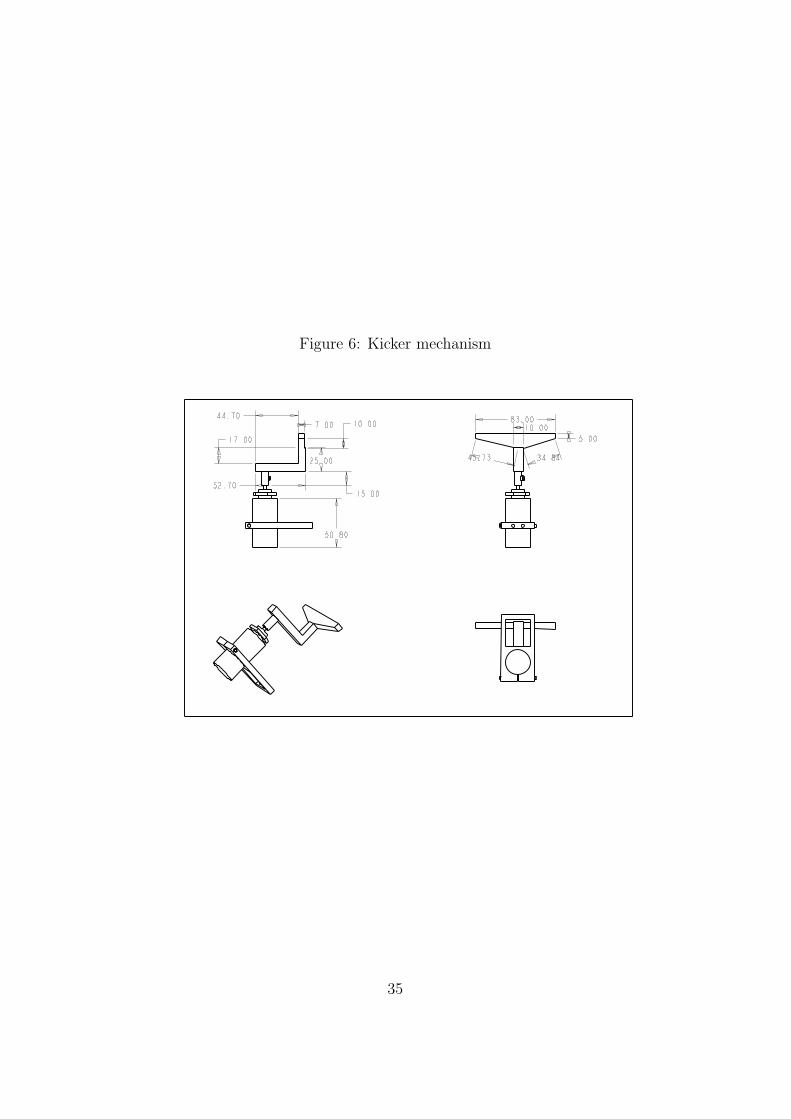
Figure 6: Kicker mechanism
35

The materials being considered are polyurethane, neoprene etc. Anotheraspect of the design which must be optimised by testing is the height atwhich the dribbler should be placed above the ground. The height wouldbe fixed so as to satisfy the 80/20 rule.Manufacturing costs
2. Dribbler MotorsThe final rpm of the ball should be such that the velocity of the ball,if it is allowed to move backwards is equal to the velocity of the robotin the backward direction. This is necessary so as to facilitate dribblingwhile moving backward. Greater rpm would also be generally helpful whiledribbling the ball while moving in various directions. Assuming a robotwhich can move backwards at around 3msec−1 , and no slippingoccurs at point of contact between dribbler and the ball, the rpmof the ball would be given by
Rpm =(3 ∗ 60)
(pi ∗ 45 ∗ (10−3))= 1260approx. (24)
Assuming the dribbler diameter of 20 mm and no gear reduction ,this would give us a minimum required motor rpm of 2835 rpm.
3. Torque Transfer assembly From the design of the entire assembly itis clear that the motor cannot be placed coaxially with the roller of thedribbler mechanism. Thus some sort of torque transfer assembly involvingbelt drives or gear systems would be necessary to transfer the torque fromthe motor to the roller. This can be done either by using belt drives orspur gears. Considering the high rpm gears will be preferable.
5.10 Overall component requirements:
5.10.1 Drive Motors:
As explained previously, we need motors which can provide stall torque of about0.36 Nm and speed 1000 rpm. Also the robot dimensions shouldnt exceed an 18cm diameter circle and a height of about 15cm. We have searched for variousmodels available in the market. Due to strict dimensional constraints, we had tolook for small DC motors.
Among the various manufacturers, MAXON and FAULHABER com-panies produce motors that can fit in dimensionally as well as fulfil thepower requirements. But as these companies are located outside India,their motors are costly and shipping them to India is a major issue.
36

Figure 7: Torque Transfer assembly
Hence we tried to look for options available in India. We contacteda dealer in Kerala, ARK Power controls Pvt Ltd. They had motors ofrequired specifications but required 36V power supply and we couldntfind any model they produced that fit in our dimensional constraints.
Miniature motors are possible due to the presence of an ironless rotor coilwhich are manufactured by MAXON and FAULHABER companies and they canprovide the required specifications with smaller dimensions, as we need for ourpurpose.
We also found out that using stepper motors that would fit in dimensionallyand provide same power would require 36V power supply. As providing 36V isdifficult for such a small robot, we couldnt find any use for the ARK motors.
As it was difficult to find motors to suit our requirements in India,we had to settle for either MAXON or FAULHABER. Following are themodel no.s and their specifications that we agreed upon for our purpose
.
Considering above specifications, we decided to go for FAULHABER
37

[]
Table 5: Comparison of MotorsModel Stall-
Torque(mNm)
No-loadrpm
GearBox Diameter(mm)
Length,with gear-box (mm)
MAXON EC45Flat orderno.200142
225 4370 Spur gear-head GS45A, Reduc-tion 5:1
45 50.8 (with-out en-coders)
FAULHABER2232SR-012SR
253 (withgearhead)
741 (withgearhead)
Spur gear-head series22/2, Ratio5.4:1
22 53.4 (en-coderlengthincluded)
motors since they have nearly the same length as the Maxon Motorsbut lesser diameter. Also we need to buy the encoders seperately forMaxon Motors over and above the Rs 10000 for the motor-gearheadassembly. Faulhaber gearhead has maximum permissible RPM of 4000;taking that into consideration the maximum speed output will be 741RPM, torque being 0.253 Nm.
With above motor, we would be able to achieve a maximum velocityof 2.24 m/sec and a maximum acceleration of 7.01 m/sec2, assumingrobot weight to be 2.5 kg.
We have found a distributor of MAXON motors in Pune and have the quo-tations for the motors, according to which each motor will cost around Rs.11,280/- per motor. We have also found a distributor for FAULHABER in Bangaloreand quotations for their motors also. Their cost comes out to be Rs.8, 725/- foreach motor (motor cost includes gearbox and encoder). Shipping charges havebeen excluded in the above prices.
We will be requiring 15 motors ( 5 bots and 3 per bot) which amountsto Rs.1, 30,875/- ( principal cost) for FAULHABER motors.
5.10.2 Solenoids:
The ball to be kicked is a golf ball and has a mass of 46 gms, diameter being43 mm. So a minimum force of 0.92 N is required assuming an accelerationof about 20 m/sec2. Also the solenoid should have stroke length of 20mm toeffectively push the ball (in case the force is not impulsive in nature).
Following is the graph of force vs. stroke length for Magnetic sensor system
38

Figure 8: FH Motors
solenoid S-20-100-H:
Force vs. stroke length curve of the S-20-100-H the model to be ordered isthe one with 3500 AT (Ampere Turns) which is meant to be used with a dutycycle of 10%
Assuming- the energy lost to friction during the kick to be negligible.- the force experienced by the ball would be equal to the force given in thediagram (a valid assumption because the return springs are quite weak and aredesigned to bring back the plunger only after the solenoid has been switched off).
Then, the area under the said curve can be equated to final kinetic energyof the ball. (F.s = mv2/2)... We have found that MAGNETIC SENSORSYSTEMS can provide solenoids with required power specifications andacceptable dimensions. The model that we will be using is S-20-100-Hwith diameter of 1 inch and length of 2.5 inch.The cost of one such solenoid is Rs.1930/- . As we will need 5 suchsolenoids, the cost estimate is around Rs.9650/-. Including the ship-ping charges of USD154, the total cost estimate for solenoids is Rs.16,267/-.
39

Figure 9: Stroke length graph
40
5.10.3 Trans-wheels:
We have got the trans-wheels from Kornylak Corporation. We got two types;four of one type have thickness 16.5 mm with 8 nylon rollers and other withthickness 50.8 mm with 16 rollers. We will be testing on these wheels in theprototype for omni-wheel drive system response.
5.10.4 Dribbler motors:
As stated previously, we need motors that can provide 40 mNm torque and speedof about 2835 RPM. As we are concerned about just the power requirements anddimensions are not an issue, we thought of getting cheaper motors for dribbler.We found a Chinese dealer SGMADAR from where we can get motorwith required power specification. Motor length is approx. 10cm anddiameter 25mm. Model no is 60JB52123600. Each motor costs USD25= Rs.1073 approx. which for 5 such motors comes out to be Rs.5, 365/-
We will be using bevel gear assembly for torque transfer. We will try to makeone ourselves. If it cannot be done then we can use bevel gearboxes availablelocally. The dribbler material we will be using for dribbler will be decided afterexperimenting with different materials on the prototype.
5.11 Weight estimates for various components:
41

Figure 10: Final assembled view
42

[]
Table 6: Weights of componentsComponent Weight per unit (gms) Number of units Total weight (gms)
Motors 62 3 186Gearhead 59 3 177
Battery (li-pos) 110 4 440Solenoid 176 1 176
Dribbler motor 100 1 100Wheels 29 3 87
Aluminium assembly 700-800 gmsTotal 1900 gms
5.12 Progress till now:
1. Decided upon the motors, solenoids required.2. In contact with Mr. Ramanujan for CNC machining facility for trans-wheeldesign.3. Ordered Trans-wheels from Kornylak.4. First prototype with differential drive has been finished. We will make secondprototype for omni-wheel drive using trans-wheels
5.13 Overall budget requirements
3
3CHF is Swiss Francs; 1 CHF=40 Rs
43

[]
Table 7: Overall mech Budget# Component Cost per unit Number Total1 FAULHABER
2232SR-102SRRs.8725 15 Rs.130875
2 Magnetic Sensorsystems S-20-100-H solenoid
Rs.1930 5 Rs.9650
3 SGMADAR Chi-nese motors
Rs.1073 5 Rs.5365
4 Kornylak Trans-wheels
7.48 USD 15 113 USD
5 Customs at 10 % 15071.46 Shipping- Faul-
Haber170 CHF
7 Shipping-Solenoids
70 USD
8 Shipping -transwheels
30 USD
9 Shipping- Chi-nese Motors
30 USD ( appcost)
10 Manufacturingand materialcosts
25K
10 Total Rs 2.05 Lakhs
6 Electrical Design
6.1 Primary Objectives:
1. Motion Control: The electronics must be able to translate the commandsgiven by the AI ( ie the velocities of each of the motors ) in a three wheeldrive system into actual motor velocities. The velocity transitions, ie fromone velocity to another must be quick ( order of less than 5 milliseconds)and the velocity actually achieved by the motor should be as as close to thetarget velocity as possible. This is an enabling feature for the AI motionplanning to be efficient.
2. Communication: To be able to decode the commands sent by the AIthrough the communication link and execute them ( ie motor velocities,
44

dribbler commands and kicker commands).
3. To be able to actuate the kicker and achieve speeds and stroke lengths asmentioned in the mechanical design objectives.
4. To be able to actuate the dribbler and move with the ball for a givendistance.
6.2 Block diagram of the electrical system:
The main micro controller is responsible for regulating all on-board operations.The following diagram depicts the sub-systems managed and information flowbetween the micro controller and the sub-systems.
6.3 Description of the subsystems in the block dia-gram:
6.3.1 Motion (drive) system:
The DC brushed motors that we propose to use are all linear in the sense thatthe rpm of the motor, for a given load, is proportional to the voltage. Hence, inorder to control the rpm, a PWM signal with a desired duty cycle is applied tothe terminals of the motor through a motor controller.
The motor controller serves to step up currents and voltages from the logiclevel ( ie those provided by the micro controller; which is the chip responsible forexecuting commands) to levels suitable for the motor to operate ( 12 V). ThePWM signal effectively provides an average voltage at the motor terminals whichis converted into a velocity proportional to the average velocity.
This method (open loop control) will work provided all loads on the motorremain constant with time and if the velocity need not be very accurate. Inpractice since our bots will have fluctuating loads and to provide accurate velocitycontrol, a closed loop, using encoders for feedback and a PID controller forcorrection, needs to implemented.
Here each of the Motor Driver controllers in the block diagram represents achip to carry out the counting of encoder pulses, followed by PID filtering andanother chip ( ie the motorcontroller (like MC33886VW) ) to step up the voltagelevels up to those of the motor . More on these chips is given below.
6.3.2 Communication interface:
Most micro controllers these days come with in-built communication facilitiessuch as the USART. In order to communicate signals to the micro; we need
45

Figure 11: Electrical block diagram
46

to convert our information from the protocol supported by the Wireless link toTTL; which can be connected directly to the micros USART pin. ICs to carryout these conversions exist and are different for different protocols. Some suchICs are the MAX232A to convert from the serial(RS 232) protocol to TTL andthe FT232RL to convert from the USB protocol to TTL. In our case, the radiomodules we get may provide the output in serial form itself thereby saving us theIC for conversion.
6.3.3 Dribbler interface:
The dribbler motor just requires a simple on /off control. Hence the interfacewill be a standard motor control chip like the MC33886VW to step up voltages.
6.4 Hardware selection for the electrical subsystems:
6.4.1 Motion Control:
Achieving motion control occurs in two stages. In the first the pulses receivedfrom the encoder channels are sampled; (at around 1 MhZ) in order to countthe number of discrete angle units covered by the wheel and to also determinethe direction of movement. The running counter ( of number of angular units)is used with a timer to determine the number of counts traversed by the motorin a given time interval; which is proportional to the motor velocity. In a similarmanner the acceleration is also calculated. The measured values of position,velocity and acceleration ( as described above) are compared with the expected(target) values and depending on the differences, the PID controller sends asignal to the motor in the form of an appropriate duty cycle PWM signal.
Implementing all these capabilities on our own, though possible is error proneand cannot give us the desired degree of accuracy besides requiring a lot ofhardware like FGPA boards. Integrated motion control chips like the LM629are designed especially for this purpose. The microcontoller just transmitsits desired velocity, position and acceleration to the chip which executes themotion control loop. By transmitting a different bit pattern ( as a command )followed by transmission of data values the micro can also set the coefficientsKp ,Kd and Ki that are essential to the PID loop.
All this happens using an 8 bit , 8 pin parallel interface between the microcontroller and the LM 629. The LM 629 generates a PWM signal that is at thelogic level ( 5V). This is stepped up using a motor controller ( since it supportshigher currents). The output from the motor controller then feeds into the motorterminal.
Apart from the LM629-8 Mhz detailed above, the PIC SERVO is
47
another chip that provides motor control. It is around 10 dollars cheaper;however its interface with the micro (serial) differs from the LM 629(parallel) which may make it slower and increase latency. Apart fromthe serial interface in the PIC SERVO and the parallel in interface in theLM 629, there is essentially no difference between the chips funcionalitywise. The chip to be used finally would be decided after testing on theprototype.
6.4.2 Micro controller/processor:
Since many sub-systems depend on the micro controller, the choice of controllerwas of pivotal importance. Numerous criteria were considered before choosingthe final micro controller; the key criteria are discussed below .Features required:
1. Processing speed 8 MHz or higher
2. Enough programmable memory
3. Ability to generate minimum of three independent PWM
4. Fast serial communication interface
5. External interrupts
6. Handle 10 interrupts at a time
7. Enough I/O pins for interfacing with the motion control chips
8. Preferably high level programming language
9. Quick and fast Programming and burning
10. Easy to debug
11. Low power consumption
12. Ability to process local feed back (for later developments)
Features listed are only tentative and minimum requirements as the project de-velops further advanced features might be required, so micro controller chosenmust have room for further developments also.
48
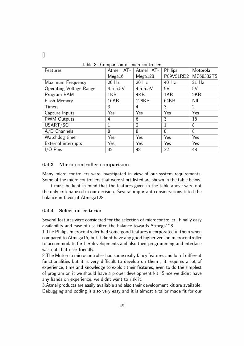
[]
Table 8: Comparison of microcontrollersFeatures Atmel AT-
Mega16Atmel AT-Mega128
PhilipsP89V51RD2
MotorolaMC68332TS
Maximum Frequency 20 Hz 20 Hz 40 Hz 21 HzOperating Voltage Range 4.5-5.5V 4.5-5.5V 5V 5VProgram RAM 1KB 4KB 1KB 2KBFlash Memory 16KB 128KB 64KB NILTimers 3 4 3 2Capture Inputs Yes Yes Yes YesPWM Outputs 4 6 3 16USART/SCI 1 2 1 8A/D Channels 8 8 8 8Watchdog timer Yes Yes Yes YesExternal interrupts Yes Yes Yes YesI/O Pins 32 48 32 48
6.4.3 Micro controller comparison:
Many micro controllers were investigated in view of our system requirements.Some of the micro controllers that were short-listed are shown in the table below.
It must be kept in mind that the features given in the table above were notthe only criteria used in our decision. Several important considerations tilted thebalance in favor of Atmega128.
6.4.4 Selection criteria:
Several features were considered for the selection of microcontroller. Finally easyavailability and ease of use tilted the balance towards Atmega1281.The Philips microcontroller had some good features incorporated in them whencompared to Atmega16, but it didnt have any good higher version microcontrollerto accommodate further developments and also their programming and interfacewas not that user friendly.2.The Motorola microcontroller had some really fancy features and lot of differentfunctionalities but it is very difficult to develop on them , it requires a lot ofexperience, time and knowledge to exploit their features, even to do the simplestof program on it we should have a proper development kit. Since we didnt haveany hands on experience, we didnt want to risk it.3.Atmel products are easily available and also their development kit are available.Debugging and coding is also very easy and it is almost a tailor made fit for our
49

requirements.. The biggest advantage came from the fact that Atmega16 can beused in the initial stages to check the circuitry as it can be used on bread boardand exploiting the fact that they have similar architecture and programminglanguage as that of Atmega128..So Atmega128 is easy to work with and since it can be developed instages starting with Atmega16 it was the ideal choice for us.
6.5 Motor Controllers:
Two chips have traditionally been used for this purpose, the L293Dand MC33886VW, and they are both easy to procure. The L293Dcan support two motors; while the MC33886VW can support only one.However the current capacity is more in the latter case.
6.6 Batteries:
By looking at the documentation of other teams we have concluded that a 2000mAh battery should provide enough energy to last one match.Since dimensionsare a major problem, we need to buy Lithium Polymer batteries; theyhave the highest energy densities. These batteries come in small packswith nominal voltages of 3.7 volts and we can connect four of these in serial toget our required voltage. The advantage of wiring together four smallerbatteries is that we can distribute them across the surface of the bot;thereby utilizing space better. Hence we would need a total of 20 suchbatteries(4*5).
6.7 List of components required:
Development tools for the Micro controller:This is a one time investment and will be useful for most future projectstoo:
1. Atmega128 microcontroller
2. Atmega16 microcontroller
3. Atmega128 development board
4. Atmega16 development board
5. Atmega128 programmer
6. Atmega16 programmer
50

7. JTAG debugger
8. Serial port dongle
9. Miscellaneous components ( resistors, capacitors, bread boards)
Other components required:
1. LM 629 for motion control.
2. MC33886VW as motordriver chip
3. Li-Polymer batteries with good capacity ( 2 Ah)
4. Li-Polymer battery charger
51

[]
Table 9: Budget Details for Electrical teamItem Cost per
unitUnits Supplier Total
Development Terminal for ATMega128(for testing)
USD59.95
1 SparkFun USD59.95
Header Board for ATMega128 USD37.95
1 SparkFun USD37.95
Header Board for ATMega16 USD22.95
1 SparkFun USD22.95
40 Pin AVR Development Board w/USBConnection for Atmega 16
USD31.95
1 SparkFun USD31.95
AVR STK Serial Port Dongle Program-mer
USD12.95
1 Sparkfun USD12.95
PIC SERVO (for testing) USD 30 3 Jrkerr USD 90AVR In Circuit Emulator with USB Inter-face for JTAG( debugging)
USD56.95
1 SparkFun USD56.95
LM 629-8 (cost may reduce if we use PICSERVO instead)
43 USD 15 Digikey 645USD
Polymer Lithium Ion Batteries -2000mAh JST Connector
USD16.95
20 SparkFun 339USD
Li-Po battery chargers 19.95USD
3 SparkFun 59.85USD
MC33886VW chips Rs 210 15 Freescale samplesPCB design and fabrication Rs
10000Zeta Mi-crosystems
Rs10000
Miscellaneous ( testing out certain chipsand other costs)
Rs 5000 Rs 5000
Shipping(assuming the SparkFun ordersare in one shot)
250USD
Customs@10% of foreign purchases afterreduction
Rs 6000
Total Rs90000
52

[]
Table 10: Total budgetTeam Cost (including overheads)
Communication Rs 14000Image Processing and arena Rs 1.8 lakhs
AI Rs 17000Electrical Rs 90000
Mechanical Rs 2.05 lakhsTotal Rs 5.16 lakhs
53


