HAL Id: hal-01170661 https://hal.archives-ouvertes.fr/hal-01170661 Submitted on 2 Jul 2015 HAL is a multi-disciplinary open access archive for the deposit and dissemination of sci- entific research documents, whether they are pub- lished or not. The documents may come from teaching and research institutions in France or abroad, or from public or private research centers. L’archive ouverte pluridisciplinaire HAL, est destinée au dépôt et à la diffusion de documents scientifiques de niveau recherche, publiés ou non, émanant des établissements d’enseignement et de recherche français ou étrangers, des laboratoires publics ou privés. Robot guidance of an ultrasound probe toward a 3D region of interest detected through X-ray mammography Marie-Aude Vitrani, Anja Marx, Razvan Iordache, Serge Muller, Guillaume Morel To cite this version: Marie-Aude Vitrani, Anja Marx, Razvan Iordache, Serge Muller, Guillaume Morel. Robot guidance of an ultrasound probe toward a 3D region of interest detected through X-ray mammography. Inter- national Journal of Computer Assisted Radiology and Surgery, Springer Verlag, 2015, pp.1861-6429. 10.1007/s11548-015-1244-8. hal-01170661
Transcript
HAL Id: hal-01170661https://hal.archives-ouvertes.fr/hal-01170661
Submitted on 2 Jul 2015
HAL is a multi-disciplinary open accessarchive for the deposit and dissemination of sci-entific research documents, whether they are pub-lished or not. The documents may come fromteaching and research institutions in France orabroad, or from public or private research centers.
L’archive ouverte pluridisciplinaire HAL, estdestinée au dépôt et à la diffusion de documentsscientifiques de niveau recherche, publiés ou non,émanant des établissements d’enseignement et derecherche français ou étrangers, des laboratoirespublics ou privés.
Robot guidance of an ultrasound probe toward a 3Dregion of interest detected through X-ray mammography
To cite this version:Marie-Aude Vitrani, Anja Marx, Razvan Iordache, Serge Muller, Guillaume Morel. Robot guidanceof an ultrasound probe toward a 3D region of interest detected through X-ray mammography. Inter-national Journal of Computer Assisted Radiology and Surgery, Springer Verlag, 2015, pp.1861-6429.�10.1007/s11548-015-1244-8�. �hal-01170661�
Abstract Purpose: This research is situated in the context of breast cancer detectionwhere the standard procedure is the succession of an initial mammography (MX) ex-amination and a supplementary Ultrasound (US) scan. One major difficulty of thisprocedure results from the fact that breast geometry changes between both examina-tions due to different patient’s positions. The proposed system facilitates this com-bined examination by keeping the breast geometry and by adding a US probe guid-ance robot to the mammography system.Methods: A co-manipulation system is set up where the robot and user simultane-ously manipulate the probe towards the target previously localized in MX images.Calibration procedures and robot control are detailed.Results: A test protocol was presented to conduct two tests that are both related to themedical application. The first tests aims at evaluating robot guidance for localizinga lesion which was previously defined in the X-ray images. The second tests aims atquantifying robot influence when scanning a target lesion. The studied task consistsof a pointing/scanning exercise, where the US beam intersects a breast lesion.Conclusions: The experiments show a significant increase in examination qualitywhen using robot guidance as compared to the non-assisted examination.
Keywords comanipulation · human-robot collaboration · breast cancer detection ·assisted gesture
1 Introduction
This work is set in the medical context of breast cancer (BC) detection. The usualBC detection procedure schedules a first x-ray examination (called mammography
A. Marx, M.-A. Vitrani and G.Morel are with (1) Sorbonne Universites UPMC Univ. Paris 06, UMR 7222,ISIR, Paris, France, (2) INSERM, U1150, Agathe-ISIR, F-75005, Paris France, (3) CNRS, UMR 7222,ISIR, F-75005, Paris, France. Email: {marx, vitrani, morel}@isir.upmc.fr, · A. Marx, R. Iordache andS. Muller are with GE Healthcare, Buc, France.
2 Marie-Aude Vitrani et al.
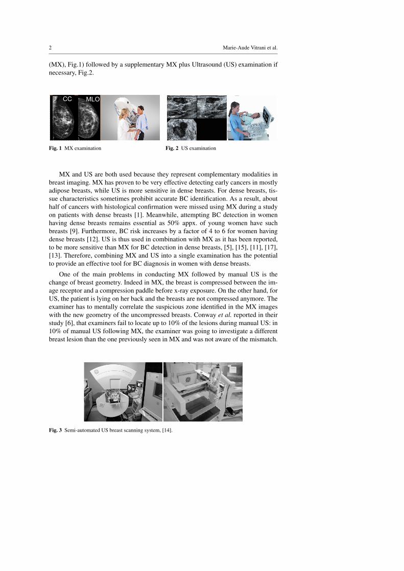
(MX), Fig.1) followed by a supplementary MX plus Ultrasound (US) examination ifnecessary, Fig.2.
CC MLO
Fig. 1 MX examination Fig. 2 US examination
MX and US are both used because they represent complementary modalities inbreast imaging. MX has proven to be very effective detecting early cancers in mostlyadipose breasts, while US is more sensitive in dense breasts. For dense breasts, tis-sue characteristics sometimes prohibit accurate BC identification. As a result, abouthalf of cancers with histological confirmation were missed using MX during a studyon patients with dense breasts [1]. Meanwhile, attempting BC detection in womenhaving dense breasts remains essential as 50% appx. of young women have suchbreasts [9]. Furthermore, BC risk increases by a factor of 4 to 6 for women havingdense breasts [12]. US is thus used in combination with MX as it has been reported,to be more sensitive than MX for BC detection in dense breasts, [5], [15], [11], [17],[13]. Therefore, combining MX and US into a single examination has the potentialto provide an effective tool for BC diagnosis in women with dense breasts.
One of the main problems in conducting MX followed by manual US is thechange of breast geometry. Indeed in MX, the breast is compressed between the im-age receptor and a compression paddle before x-ray exposure. On the other hand, forUS, the patient is lying on her back and the breasts are not compressed anymore. Theexaminer has to mentally correlate the suspicious zone identified in the MX imageswith the new geometry of the uncompressed breasts. Conway et al. reported in theirstudy [6], that examiners fail to locate up to 10% of the lesions during manual US: in10% of manual US following MX, the examiner was going to investigate a differentbreast lesion than the one previously seen in MX and was not aware of the mismatch.
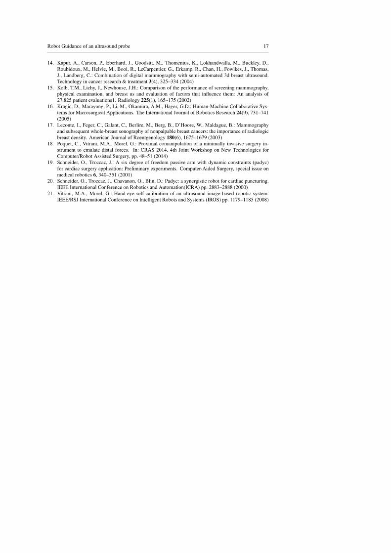
Fig. 3 Semi-automated US breast scanning system, [14].
Robot Guidance of an ultrasound probe 3
To overcome these difficulties, Kapur et al. proposed an imaging apparatus tocombine MX and automated US scans [14], see Fig.3. A 2 degrees of freedom (DOFs)robotized probe holding framework is mounted on top of the compression paddle.During the US examination, the probe is automatically moved over the compressionpaddle and the images are further treated in order to display the scanned US volume.MX and US images are displayed in real time. Since US coupling gel might have anegative affect on MX image quality, MX is performed prior to US. A clear advan-tage of this approach is that the patient’s breast remains under the same compressionduring MX and US. A drawback in the context of diagnostic procedures is that it maytake time to fully scan the breast volume with the US probe, while the medical needis often to check a particular suspicious region that was detected on MX. Moreover,when shadows appear from either anatomical structures or paddle support, it is notpossible to adapt the probe’s orientation because of the limited DOFs of the scanningdevice.
The concept developed in this paper uses the same idea of performing the USexamination right after the MX imaging, the patient’s breast remaining under thesame compression. However, instead of an automatic scanning with limited num-ber of DOFs, we propose a manual manipulation of the US probe towards a targetlocalized in the MX image, with six DOFs. This manipulation is assisted by a coma-nipulated system.
Comanipulation consists in sharing the control of a tool between a user and arobot. A typical behavior is set through Virtual Fixtures. Virtual fixtures are geomet-rical constraints imposed by a robot to a tool: along some DOFs, the movement isfree for the user while along the others, it is blocked up to the robot programmablestiffness.
This idea was implemented in [20] and [19], through a semi-passive device calledPassive Arm with Dynamic Constraints (PADyC). Its mechanical design enables themotion of a tool to be limited in accordance with a planned task. A geometric zone isdefined in which the surgeon can move freely. When moving out of the zone the sur-geon is restricted by forces applied by the robot, which prevents the tool from leavingthe prescribed zone. Since then, comanipulation and virtual fixtures have been widelyused for surgical applications ranging from orthopedic surgery, [7], [3], [10] to eyesurgery [16], through key-hole interventions, [18]. The application of comanipulationto the placement of an US probe following an MX exam for BC detection is detailedin Sec.2. This application requires a full system calibration, which is described inSec.3 and an original controller described in Sec.4. A set of in vitro experimentalresults is given and discussed in Sec.5 prior to a conclusion (Sec.6).
2 Proposed approach
The workflow of the proposed system begins with a 3D Mammography so-calledDigital Breast Tomosynthesis (DBT) scan of the patient’s breast, see Fig.4. After 3Dreconstruction of the breast a suspicious zone is identified. Its coordinates are sentto the robot in order to provide assistance when locating the target lesion. The userjointly manipulates the probe with the robot. His/her task is to image the suspicious
4 Marie-Aude Vitrani et al.
zone while maintaining contact between the probe and the paddle. The robot task is to
detectorbreast
compressionpaddle
X-raybeam
X-ray emittingsource
lesion localizationby physician
3D reconstruction
physician
US probe
coordinates transmissionto robot
Fig. 4 Novel system for robot assistance for com-bining US and DBT examinations.
O0 x0
y0
OX xX
yX PxU
yU
O6 x6
y6
Fig. 5 Test Setup
help the radiologist thanks to virtual fixtures, see Fig.4. Indeed, from the physician’spoint of view the US scan remains complex: to position the probe, the shape and 3D-location of the suspicious lesion must still be mentally reconstructed from the DBTimages. This computation can be performed easily by a computer and the informationcan then be sent to a robot, which should guide the physician towards the lesion withincreased speed and accuracy. Fig. 5 depicts the complete setup built to experimentthis idea. A Virtuose 6D (Haption, France) robot is used. It is a fully actuated 6-DOFshaptic robot which is designed to produce forces and moments at its end-effector witha high fidelity. Adaptable fixations were built to mount on the robot end-effector a9L linear transducer (Ultrasonix, France) connected to an Ultrasonix RP Ultrasoundsystem.
As for the breast, a multi modal breast phantom (Cirs inc. model 051 phantom)containing dense masses of 2 to 8 mm diameter and cystic lesions of 3 to 10 mmdiameter is used. It is compressed between a 25 mm thick PVC plate (at the bottom)and a 6 mm thick PMP plate (at the top), both well suited regarding their low x-rayattenuation, PMP being equally well suited to let pass US [4]. Figure 6 show typicalUS-image of a lesion obtained with this set-up. A computer screen is placed in frontof the subject and displays the reconstructed slices of the breast phantom, acquiredusing an investigational DBT device based on a Senographe DS (GE Healthcare,Chalfont St Giles, UK). The subjects are free to navigate within the DBT imagesusing the scroll ball of a computer mouse, as it is done during the standard workflowof mammography image reading.
3 System calibration
The proposed approach leads to calibration and registration issues. The target I isfirst identified in the MX images. Its position in the breast phantom is thus knownw.r.t. the x-ray DBT reconstructed slices. The aim is to program the robot assistingthe positionning of the probe towards the target. Therefore, it is required to determine
Robot Guidance of an ultrasound probe 5
Fig. 6 US image during tests. Left: breast border,Top: artifacts due to compression paddle, Bottom:artifacts due to plate simulating the detector, Mid-dle: cystic lesion (black) and tumor lesion (white)
Fig. 7 X-ray image during tests.
the position of I w.r.t. the ultrasound probe. Two essential localization informationare necessary:
– the US-beam localization in robot base (Fig. 8), expressed through the homoge-neous translation matrix M0P, resulting from the product of:
– the robot end effector localization w.r.t. the robot base, M06, (calibration de-tailed in Sec.3.1),
– and the US-beam localization w.r.t. the robot end-effector, M6P, (calibrationdetailed in Sec.3.2),
– the x-ray image frame localization w.r.t. the robot base, M0X , (Fig. 9), (registrationdetailed in Sec.3.3).
In the next, the following coordinate frames will be used:
– FP = (P,xP,yP,zP), the frame attached to US-probe, with P being the probe tipand zP the normal vector of the US-plane. Note that (P,xP,yP) is the US image-plane.
– F0 = (O0,x0,y0,z0), the frame attached to the robot base.– F6 = {O6,x6,y6,z6} the coordinate system of the robot end-effector.– FX = {OX ,xX ,yX ,zX} the coordinate system of the x-ray DBT reconstructed
slices, with OX being the upper left image corner and zX the image’s normalvector.
O6
O0
x0
y0
y6x6
M06
yP
xP
M0P
M6P
P
Fig. 8 Ultrasound probe to robot base calibrationprinciple.
O6
O0
x0
y0
y6
x6
xX
yX
OX
M0X breast phantom
Fig. 9 x-ray image to robot base registration princi-ple.
6 Marie-Aude Vitrani et al.
3.1 Robot Identification
In this system, a cable-driven robot is used. This type of robot may show internalposition errors due to their mechanical structure (cable deformations). To interpretthe calibration and registration results in their given context, the precision of the robotwas determined first. A conventional geometry calibration procedure was run, leadingto the identification of the Denavit-Hartenberg (DH) parameters for the Virtuose 6D[8]. DH parameters correspond to the geometrical constants of the robot (link lengths,angles between axes).
The identification consists in minimizing (with an iterative least-square algo-rithm) the error between two measures of the position of a given end-effector pointM. The first measure is obtained from the robot joint sensors and a geometrical modelinvolving the DH parameters to be identified. The second measure is obtained froman external reference measure. In these experiments, the Polaris visual tracking sys-tem (Northern Digital Inc.) with a known position error noise of 0.4 mm was used forreference measures, while a visual marker was fixed at the robot end-effector (pointM). The robot was positioned in different configurations and the robot and markerspositions are recorded in both systems respectively (i.e. Virtuose 6D and Polaris).A total of 37 measures have been used for the identification. The mean end-effectorposition error after convergence was 1.64 mm (max 2.65 mm, std dev 0.64 mm). Theoptimized parameters were verified with 13 points not used for optimization, givingan average error of 1.49 mm (max 2.64 mm, std dev 0.81 mm).
O6
O0
OVOM
O6 OM
Fig. 10 Verification results of the DH identification algorithm for the Virtuose 6D robot.
3.2 Ultrasound Probe To Robot End Effector Localization
Calibrating the US-probe with respect to the robot end-effector aims at localizingevery US image pixel in the robot end-effector frame, i.e. determining the transfor-mation matrix M6P between F6 and FP. The approach depicted in [21] is used: arectilinear rod plunged in a water tank is observed by the US probe for several robot
Robot Guidance of an ultrasound probe 7
configurations (see Fig.11). The intersection of the calibration rod with the US-planeresults in a white blob in a mostly black US image and thus its geometrical center(GC) can easily be localized in the US image. The identification procedure consists
O6
O0
x0
y0OR
s
M
PP
Fig. 11 Geometrical Model For US-Probe Calibration.
in minimizing (thanks to a recursive least square algorithm) the error between twodifferent measures of the GC coordinates in the end-effector frame. One results fromthe geometrical model of the robot and the other from image processing. Note that theidentification procedure also allows for identifying the US image gains, namely themm to pixel ratio, see [21]. The calibration algorithm is ran from 16 configurations. Itconverges with an average error of 1.17 mm (max 2.41 mm, std dev 0.60 mm). In theUS image, these correspond to a reconstructed error per direction of 3.12 pixels (max8.42 pixels) and 7.66 pixels (max 18.22 pixels) in x- and y-direction respectively. Theoptimized parameters were verified with 7 points not used for optimization. Verifica-tion terminated with an average error of 0.78 mm (max 1.74 mm, std dev 0.51 mm), see Fig.12. In the image, these correspond to a reconstructed error per direction of1.42 pixels (max 3.60 pixels) and 5.77 pixels (max 12.86 pixels) in x- and y-directionrespectively.
250 300 350 400 450 500350
400
450
500
x [px]
y [p
x]
measured and reconstructed U\S image coordinates of verification points after optimization
measuredreconstructed
0 1 2 3 4 5 6 7 80
0.5
1
1.5
2x 10
−3
U\S verification point
U\S
ver
ifica
tion
erro
r [m
]
x directiony directionerror normmean error
Fig. 12 Parameter verification for ultrasound probe calibration.
8 Marie-Aude Vitrani et al.
3.3 X-ray image Registration
Since the robot is not localized with respect to the mammography device, a regis-tration step is necessary to obtain the transformation matrix between F0 and FX .The chosen method relies on mesuring the coordinates of reference points in boththe robot and x-ray image space. The registration tool is a nylon plate containing 15lead ball bearings (BBs) which was positioned on top of the breast phantom. Fiducialmarkers have been randomly placed on a plate covering the entire breast phantomsurface. The markers are 1 mm diameter BBs highly visible in x-ray images. An x-ray scan of the registration plate is performed. The BBs coordinates are determinedin the x-ray images. To obtain the coordinates of the target points in the robot space,a localization tip was used. Each target point coordinates w.r.t. the robot base arecomputed thanks to DH parameters identified in Sec.3.1 and to a tool model.
The registration points on the nylon paddle are determined in the robot base bymanually pointing on them using the robot equipped with the calibrated tool (seeFig.13). During this phase, the robot is controlled to apply a null force and it canbe easily moved thanks to its high backdrivability. The obtained coordinates are thenmapped to the point coordinates determined in the MX images. This mapping is doneusing an iterative closest point algorithm (ICP), [2].
xB
yB
OBOL
O6
O0
Fig. 13 Geometrical model for x-ray image registration.
Nine marker coordinates are used to optimize the transformation parameters. Theremaining five points are used to verify the optimization algorithms and to confirmthe error. The chosen target points for optimization and validation are distributed allover the registration plate. The ICP algorithm terminates with an average error of0.70 mm (max 1.06 mm, std dev 0.24 mm). The optimized parameters were verifiedwith 5 points, giving an average error of 0.73 mm (max 1.59 mm, std 0.48 mm), seeFig.14.
3.4 Total Setup Error
To estimate the final set-up error, six target points (lesion GC of the anatomic phan-tom) were chosen. Their coordinates were determined in the x-ray and US images.For the latter ones, the US-probe was positioned manually. After successful calibra-tion of each system component, both independent ways to measure the same targetpoint should give the same result. A difference between both measures indicates a
Robot Guidance of an ultrasound probe 9
0.60.62
0.640.66
−0.08−0.06
−0.04−0.020
x [m]
reconstructed and measured sphere positions for verification after phantom registration
y [m]
z [m
]
measuredreconstructed
0 1 2 3 4 5 60
0.5
1
1.5x 10
−3
phantom registration verification point
phan
tom
reg
istr
atio
nve
rific
atio
n er
ror
[m]
x directiony direction
z directionmean error
Fig. 14 X-ray image to robot verification.
calibration/registration error of the system. Thus, the GC were measured in FP andFX separately. To estimate the error between both sets, they were expressed in FP.The transformation from FX to FP is possible thanks to the previous calibrationsteps. Indeed, any point QX |X expressed in FX can be expressed in FP by:
QX |P = MPX QX |X = MP6 M60 M0X QX |X (1)
Target points have been identified in the breast phantom to estimate the total setuperror. The point coordinates have been determined in the x-ray images, QX in Fig.15.The same target points have been visualized using US and are denoted QP. Thanksto the previous probe to end-effector calibration, the distance between QX and theUS-beam could be calculated:
dz = |(QX −QP)T zP| (2)
The average distance between the GC measured in x-ray images and the US beam is
U
π
O0
z0
y0x0
yP
zPxP
PQ
P
XQdz
Fig. 15 Geometrical model total set-up error.
1.29 mm (max 2.23 mm, std 0.84 mm), see Fig.16. Note, that this estimation dependson the manual position capabilities. A human error is thus induced in this procedure.Nevertheless, the US-probe was positioned by a user who already knew the breastphantom while paying much attention. The total set-up error is due to the followingidentified possible sources of error:
10 Marie-Aude Vitrani et al.
0 1 2 3 4 5 6 70
0.5
1
1.5
2
2.5
x 10−3
final error estimation target point
erro
r be
twee
n U
\S p
lane
and
targ
et C
OG
[m]
final set−up error−estimation comparing data from U\S and MX images
Fig. 16 Total set-up error.
– the robot internal position error,– the BBs used for registration and their diameter of 1 mm,– the reconstruction distance of 0.5 mm between the x-ray image slices (relatively
low resolution),– the localization-tip diameter of 0.25 mm,
Taking into account the medical context in which this system would be used, the totalerror looks pretty acceptable. Indeed, the smallest lesions detected in clinical practicewith US are about 5 mm in diameter.
4 Robot Control
Robot-assisted US examination of BC detection can be modeled as a pointing / scan-ning task where the user is assisted by a robot, who knows the location of the le-sion. Since the breast remains compressed after MX, the US scan is to be performedthrough the compression paddle. The radiologist’s task is to find and scan the suspi-cious zone while maintaining contact between the probe and the paddle. For bettervisibility, physicians often display the lesion in the middle of the US image, on it’smain axis. The task of a conventional US scan has a total of 6 DOFs. However, it can
lesion S US plan U
compressionpaddle Π
user
US probe
translation 1translation 2
I1
I2I
H
P
R
rotation 1
O0y0
z0
x0xP
yP
rotation 2
l1l2
lp
Fig. 17 DOF of a US scan of a compressed breast through a rigid compression paddle.
be reduced to a 4-DOFs task at the probe-tip thanks to the assumption of constant
Robot Guidance of an ultrasound probe 11
probe-paddle contact. Two movements would lead to a loss of probe-paddle contactand thus are not part of the task:
– translations along the paddle normal vector,– rotations around vector normal to the US beam.
The positioning task possesses thus 4 DOF, as shown in Fig.17: two translations of theprobe-tip on the paddle, assumed to be planar, one rotation along the normal vector ofthe paddle surface, and a second rotation around the intersection line of the paddle-surface and the US-plane. Even if the task is associated with scanning, i.e. the fullcoverage of a region of interest (ROI), this can be reduced to a pointing task based onthe hypothesis of a moving point of interest (POI) within the ROI. The compressionpaddle is associated with a plane π while the ultrasound beam plane is denoted U. Inthe next, the following notations are used:
– The US-probe is handled by the user at point H on the US-probe main axis.– The robot wrench is applied on the probe at point R on the US-probe main axis.– The central point of the suspicious lesion S is denoted I and its projection on U is
denoted I1 with I1− I = l1zP.– The projection of I on the US-probe main axis is denoted I2, I2− I1 = l2xP.
The task consists of centering the suspicious lesion in the image, which is hencedivided into two parts:
1. assuring intersection between the US-plane and the lesion (I = I1),2. centering the lesion in the image (I1 = I2).
As stated in Sec.1, it is important to allow imaging tissues surrounding the lesion, aswell as letting the radiologist to choose the probe orientation in order to avoid unde-sired shadows and to observe the lesion from a desired angle of view. Consequently,the robot should not completely prevent the user from moving away from the target.To simulate such behavior, a robot control that generates a wrench correspondingto the sum of two compression springs of stiffness, k1 and k2 respectively, was im-plemented. Both springs have a null free length. One connects I and I1 whereas thesecond one connects I1 and I2:
E1 =[0 0 −k1l1 0 0 0
]TI1
; E2 =[−k2l2 0 0 0 0 0
]TI2
(3)
The applied wrenches thus provide a state of equilibrium at I = I1 and I1 = I2, whenthe task is successfully accomplished. The complete wrench applied to execute thetask is the sum of E1 and E2:
Etask = E1 +E2 (4)
= =[−k2l2 0 −k1l1 −k1l1lP −k1l1l2 k2l2lP
]TP with (I2−P) = lPyP. (5)
This controller is applied to the robot at a 1kHz rate. In order to ease the manipulation,a viscosity term depending on the end-effector velocity at O6 is added for properdamping, while a gravity compensation of the US probe’s weight is added.
12 Marie-Aude Vitrani et al.
5 Experiments
5.1 Protocol
Tests have been performed by 22 naive subjects using the setup. A large numberof subjects has been recruited to account for inter-subject variability and still obtainstatistically significant results. It was not possible to recruit such a large number of ra-diologists. This is why the results are not to be considered as an absolute performanceevaluation but, rather, as a differential comparison between assisted and non-assistedmanipulation. Notice that since the task to be realized is not a conventional clinicalgesture, even radiologists would have been considered as naive subjects with respectto the task and the robot assistance.
For Test 1, the subjects are presented with a target lesion chosen in the MX im-ages. They start (at t = 0) with the US-probe in its rest position (at one corner ofthe breast phantom) and have to localize this particular target on the phantom usingUS. When subjects think they have localized the lesion from a first guess, they givea vocal feedback (at t = t1). Then, they proceed to analyze the surrounding tissues(seeking for other points of interest) in order to verify their first guess, as a radiolo-gist would do in a real situation. Once they are certain to have localized the lesion,a second vocal feedback is given (at t = t2) and the test is stopped. During Test 2,the subjects are asked to scan the entire target lesion (not only its central point) usingUS. This corresponds to a clinical phase where the radiologist wants to characterizethe lesion (shape and size). Test 2 starts (at t = t3) with the US-probe already po-sitioned above the lesion to be examined. Four different scanning methods are usedwithin Test 2. First, the user is asked to visualize the lesion in the US images un-der as many different perspectives (probe orientations) as possible within 30 sec. Forthe three remaining scanning methods, the subject is asked to execute a particularmovement and has only 10 sec to scan the lesion. Three movements compatible withthe probe-paddle contact geometry are selected: translations along the compressionpaddle plane, rotations around the paddle normal vector nπ and rotations around theintersection of the US-plane and the paddle surface (zP× nπ ). Test 2 terminates att = te. The two tests performed are summarized here, see Fig.18:
– Test 1: subtask one and two: approximate target localization followed by propertarget identification.
– Test 2: subtask three: entire target lesion-scan.
timet0probe in rest position
t1
subtask 1 ongoing
first lesionguess
subtask 2 ongoing
t2final lesiondesignated
tescan
terminated
subtask 3 ongoing
t3scan started
Fig. 18 Time line for Tests.
The test are run under two conditions: either the robot is in a transparent mode(no forces applied, mode 1) or the robot applies the elastic force fields depicted in
Robot Guidance of an ultrasound probe 13
Sec.4 (mode 2). To avoid increasing learning effects, all tests 1 (for both actuationmodes) have been executed in a row and prior to tests 2. The subjects have thus notbeen habituated to the phantom geometry during tests 1. User performances for eachmode were compared. For tests 1, two performance indicators were chosen:
– US plane-to-target distance (precision), dz = mean(|(I− I1)
T zP|),
– completion time (duration), t2.
In order to compare the different time performances, they were normalized over theentire duration of the series of tests 1 for each subject and both actuation modes, e.g.
for mode i: tl,i =t2,i− t0,i
2∑1(t2,i− t0,i)
.
Results of tests 2 have been grouped for each actuation mode, independent of themovement. The performance indicators are:
– The visibility ratio ts defined as the ratio between the time span when US-plane Uand lesion volume S intersect (i.e. when the lesion is visible) and the total duration
of the scanning test: ts =t ′s
te− t2, with t ′s =
te
∑t2
(ti− ti−1),∀ti ∈ {t3, . . . , te} : (S∪U)
and te− t2 = 30s as imposed by the protocol.– the US plane-to-target distances (precision), dz = mean
(|(I− I1)
T zP|),
Test data has been analyzed using statistical ANOVA (analysis of variance) tests.It indicates whether or not the results obtained per control mode are significantlydifferent. The result of ANOVA tests gives so-called p- and F-values which have tobe interpreted w.r.t. level of confidence as shown here:
– the F-value is the ratio of the variance between control modes and the variancewithin each control mode. It quantifies the separation of each sampling group(here control mode) w.r.t. the others. The higher the F-value, the more the sam-plings (control mode) are significantly different.
– the p-value depends on the actual F-value. A low p-value indicates a high confi-dence in the given statistical result. For a low p-value, it is highly probable thatthe control modes have significant influence on user performances.
In case of p < 0.05, one can conclude that the robot control modes have altered theeffects on user performances in relation to the analyzed data to a significance level of95%.
5.2 Results
Table 1 shows the number of properly located lesions for each control mode at theend of Tests 1.
Table 2 shows how subjects changed their guess between the first and second feed-back. Without guidance, two subjects rectified their first guess and one finally chosea wrong lesion as target although it was properly localized at the first feedback. Onesubject rectified his initial guess with assistance, in a positive way.
14 Marie-Aude Vitrani et al.
Table 1 Number of properly located lesions during Tests 1 over 22 subjects
Indicators for tests 1 averaged across subjects are plotted in Fig.19. The averagenormalized time needed to localize the lesion was longer in mode 1 (tl,1 = 58.1%,σ=15.1%) than in mode 2 (tl,2 = 42.0%, σ=15.1%), which represents a 28.0% timereduction brought by the robot guidance. Users also performed worst with mode 1regarding precision. In this mode, the average US plane-to-target distance, (dz) is0.8 cm (1.43 cm), while it is only 0.05 cm (0.17 cm) in mode 2. This represents animprovement of 94.0% brought by robot guidance. This accuracy can be consideredsufficient to image lesions of 0.5 cm diameter in practice.
1 20
10
20
30
40
50
60
70
80
tota
lscom
plet
ions
times
[%]
actuationsmode
1 20
0.005
0.01
0.015
0.02
0.025
actuationsmode
mea
nsU
\Ssp
lane
stota
rget
sdis
tanc
es[m
]
Fig. 19 Results of Tests 1: mean localization timeand US plane-to-target distance.
1 20
20
40
60
80
100
actuationhmode
hvis
ible
hlesi
onh[%
]h
1 20
0.005
0.01
0.015
actuation mode
U\S
hpla
nehto
targ
ethd
ista
nceh
[m] maxhdist.
meanhdist.
timeh
ratio
hwith
Fig. 20 Results of Tests 2: results for visibility ratioand US plane-to-target distance.
One factor ANOVA with subjects as repeated measures was used to analyse eachindicators. The robot guidance has a significant effect on the US plane-to-target dis-tances (F = 7.2 and p = 0.014). Results of completion time (F = 6.3 and p = 0.020)showed a less but still significant effect for the experiment conditions. Indicators forTest 2 are plotted in Fig.20. With mode 1, the visibility ratio ts averaged across sub-
Robot Guidance of an ultrasound probe 15
jects was 56.7% (std dev 3.3%) of the total duration of Tests 2. Users have thus onlyspent about half of the time imaging the lesion, the rest of the time, it was not visiblein the US images although they were explicitely asked to maintain visibility duringthe scanning movement. With mode 2, ts reached 89.8% (std dev 3.4%). The target toplane distance averaged across subjects, dz was analyzed regarding its mean and max-imum values across the four different scanning methods of Tests 2, denoted mean(dz)and max(dz) respectively. The indicator max(mean(dz)) is larger in mode 1 (0.95 cm(std dev 0.47 cm)), to be compared to 0.16 cm (std dev 0.1 cm) for mode 2. The max-imal distance was thus decreased by 83% by the use of guidance. A similar relationcan be observed for mean(dz). Its value is 0.35 cm (std dev 0.09 cm) for mode 1 andonly 0.06 cm (std dev 0.03 cm) for mode 2. This corresponds to an improvement of82%. One factor ANOVA run with subjects as repeated measures again showed a sig-nificant effect of the two actuation modes: F = 210.8, p = 0.0007 for visibility ratio,F = 17.2, p = 0.0250 for max US-plane to target distance and F = 80.2, p = 0.003for mean US plane-to-target distance. P-values are equally below 0.002 for results ofeach independent tests 2 series (i.e. free movement or the three imposed movements).
6 Discussion and conclusion
The aim of this work was to propose a solution for combining MX and US breast-scans without changing the breast geometry. This is motivated by clinical literaturereporting diagnostic errors due to breast geometry changes between MX and US ex-aminations. In order to minimize the dual-examination duration, which is crucial asbreast compression induces pain to the patient, we have proposed to assist the physi-cian in locating, with the US probe, a lesion identified in the 3D MX images. Acomanipulated robot was developed to help scanning the breast with an US probethrough the MX compression paddle.
In order to allow for immediate operation as soon as the patient is installed, wehave proposed to install the robot fixed w.r.t. the DBT imaging device and to calibratethe system. The over-all system precision is 1.29 mm which is sufficient with regardto the clinical application, where lesions of 5 mm need to be identified.
A test protocol was presented to conduct two tests that are both related to themedical application. The first tests aims at evaluating robot guidance for localizinga lesion which was previously defined in the X-ray images. The second tests aims atquantifying robot influence when scanning a target lesion. The studied task consistsof a pointing/scanning exercise, where the US beam intersects a breast lesion.
Table 1 shows a slight increase in the ability of properly identifying the target le-sion thanks to the use of the robot. The low stiffness used throughout the experimentsin order to let the user scan the system is certainly a reason for that low improvement,which is yet of approx. 10%. More importantly, the use of a robot increases precisionduring both tests, nearly 94%. Furthermore, it decreases the time needed to properlylocalize a target using US by nearly 30%. During the scanning phase, the visibilityratio was increased by 60%, indicating that keeping the lesion visible during the USscanning phase is easier. We hypothesize that this could allow for localizing smallerlesions.
16 Marie-Aude Vitrani et al.
In summary, it was shown that user performance increased significantly withrobot assistance in terms of speed and precision.
Conflict of interest : This work is partially funded by ANRT under CIFRE grant247/2009 and by french state funds managed by the ANR within the Investissementsd’Avenir programme (Labex CAMI) under reference ANR-11-LABX-0004.The authors declare that they have no conflict of interest.
Research involving human participants: All procedures performed in studiesinvolving human participants were in accordance with the ethical standards of the in-stitutional and/or national research committee and with the 1964 Helsinki declarationand its later amendments or comparable ethical standards.This article does not contain any studies with animals performed by any of the au-thors.
Informed consent: Informed consent was obtained from all individual partici-pants included in the study.
References
1. Berg, W.A., Blume, J.D., Cormack, J.B., Mendelson, E.B., Lehrer, D., Bhm-Vlez, M., Pisano, E.D.,Jong, R.A., Evans, W.P., Morton, M.J., Mahoney, M.C., Hovanessian Larsen, L., Barr, R.G., Farria,D.M., Marques, H.S., Boparai, K.: Combined screening with ultrasound and mammography vs mam-mography alone in women at elevated risk of breast cancer. The Journal of the American MedicalAssociation (JAMA) 299(18), 2151–2163 (2008)
2. Besl, P.J., McKay, H.D.: A method for registration of 3-d shapes. IEEE Transactions on PatternAnalysis and Machine pp. 227–241 (1992)
3. Bonneau, E., Taha, F., Gravez, P., Lamy, S.: Surgicobot: Surgical gesture assistance cobot for maxillo-facial interventions. Perspectives in Image-Guided Surgery pp. 353–360 (2004)
4. Booi, R.C., Kruecher, J.F., Goodsitt, M.M., O’Donnell, M., Kapur, A., LeCarpentier, G.L.,Roubidoux, M.A., Fowlkes, J.B., Carson, P.L.: Evaluating thin compression paddles for mammo-graphically compatible ultrasound. Ultrasound in Medicine & Biology 33(3), 472–482 (2007)
5. Buchberger, W., Niehoff, A., Obrist, P., DeKoekkoek-Doll, P., Duenser, M.: Clinically and mammo-graphically occult breast lesions: detection and classification with high-resolution sonography. Semi-nars in Ultrasound, CT and MRI 21(4), 325–336 (2000)
6. Conway, W., Hayes, C., Brewer, W.: Occult breast masses: use of a mammographic localizing gridfor us evaluation. Radiology 181(1), 143–146 (1991)
7. Davies, B., Fan, K., Hibberd, R., Jakopec, M., Harris, S.: A mechatronic based robotic system for kneesurgery. IASTED International Conference on Intelligent Information Systems pp. 48–52 (1997)
8. Dombre, E., Khalil, W.: Robot Manipulators: Modeling, Performance Analysis and Control. ControlSystems, Robotics and Manufacturing Series (2007)
9. D’Orsi, C., Bassett, L., Berg, W.: Breast Imaging Reporting and Data System: ACR BI-RADS-Mammography, 4 edn. Reston, VA, American College of Radiology (2003)
10. Francoise, V., Sahbani, A., Morel, G.: A comanipulation device for orthopedic surgery that generatesgeometrical constraints with real-time registration on moving bones. In: Robotics and Biomimetics(ROBIO), 2011 IEEE International Conference on, pp. 38 –43 (2011)
11. Gordon, P., Goldenberg, S.: Malignant breast masses detected only by ultrasound: a retrospectivereview. Cancer 76(4), 626–630 (1995)
12. Harvey, J.A., Bovbjerg, V.E.: Quantitative assessment of mammographic breast density: Relationshipwith breast cancer risk1. Radiology 230(1), 29–41 (2004)
13. Kaplan, S.: Clinical utility of bilateral whole breast us in the evaluation of women with dense breasttissue. Radiology 221(3), 641–649 (2001)
Robot Guidance of an ultrasound probe 17
14. Kapur, A., Carson, P., Eberhard, J., Goodsitt, M., Thomenius, K., Lokhandwalla, M., Buckley, D.,Roubidoux, M., Helvie, M., Booi, R., LeCarpentier, G., Erkamp, R., Chan, H., Fowlkes, J., Thomas,J., Landberg, C.: Combination of digital mammography with semi-automated 3d breast ultrasound.Technology in cancer research & treatment 3(4), 325–334 (2004)
15. Kolb, T.M., Lichy, J., Newhouse, J.H.: Comparison of the performance of screening mammography,physical examination, and breast us and evaluation of factors that influence them: An analysis of27,825 patient evaluations1. Radiology 225(1), 165–175 (2002)
16. Kragic, D., Marayong, P., Li, M., Okamura, A.M., Hager, G.D.: Human-Machine Collaborative Sys-tems for Microsurgical Applications. The International Journal of Robotics Research 24(9), 731–741(2005)
17. Leconte, I., Feger, C., Galant, C., Berlire, M., Berg, B., D’Hoore, W., Maldague, B.: Mammographyand subsequent whole-breast sonography of nonpalpable breast cancers: the importance of radiologicbreast density. American Journal of Roentgenology 180(6), 1675–1679 (2003)
18. Poquet, C., Vitrani, M.A., Morel, G.: Proximal comanipulation of a minimally invasive surgery in-strument to emulate distal forces. In: CRAS 2014, 4th Joint Workshop on New Technologies forComputer/Robot Assisted Surgery, pp. 48–51 (2014)
19. Schneider, O., Troccaz, J.: A six degree of freedom passive arm with dynamic constraints (padyc)for cardiac surgery application: Preliminary experiments. Computer-Aided Surgery, special issue onmedical robotics 6, 340–351 (2001)
20. Schneider, O., Troccaz, J., Chavanon, O., Blin, D.: Padyc: a synergistic robot for cardiac puncturing.IEEE International Conference on Robotics and Automation(ICRA) pp. 2883–2888 (2000)
21. Vitrani, M.A., Morel, G.: Hand-eye self-calibration of an ultrasound image-based robotic system.IEEE/RSJ International Conference on Intelligent Robots and Systems (IROS) pp. 1179–1185 (2008)