44
1 Robotic Arm

1
Robotic Arm

2
Legal Stuff
● Stensat Group LLC assumes no responsibility and/or liability for the use of the kit and documentation.
● There is a 90 day warranty for the Sten-Bot kit against component defects. Damage caused by the user or owner is not covered.
– Warranty does not cover such things as over tightening nuts on standoffs to the point of breaking off the standoff threads, breaking wires off the motors, causing shorts to damage components, powering the motor driver backwards, plugging the power input into an AC outlet, applying more than 12 volts to the power input, dropping the kit, kicking the kit, throwing the kit in fits of rage, unforseen damage caused by the user/owner or any other method of destruction.
● If you do cause damage, we can sell you replacement parts or you can get most replacement parts from online hardware distributors.
● If you need to contact us, go to www.stensat.org and click on contact us.

3
Parts List
● Robotic Arm segments
●
● 4 4-40 ¼ inch screws
● Cable
● XBEE module or Wifi module

4
What is a Servo
● A servo is a geared motor with a feedback used to control the position of the shaft of the motor or spline.
● The servo consists of a motor that drives a bunch of gears to reduce the speed of the output spline or shaft. A potentiometer or variable resistor is connected to the output shaft and turns with the shaft. As it turns clockwise or counter clockwise, the resistance of the potentiometer changes. The resistance value indicates the angle of the shaft.

5
What is a Servo
● The potentiometer feeds a voltage signal based on the position of the shaft. A reference signal feeds a voltage signal for the desired position.
● The error detection circuit compares the two voltages and generates a voltage to power the DC motor in the desired direction until the position signal equals the reference signal.
● When the position signals equals the reference signal, the DC motor stops turning and the shaft is at the right angle.
DCMotor
MotorDrive
Power
Reference Signal
Position Signal
Error Detection CircuitMotor Driver Circuit
Output ShaftGears to reduceshaft speed
Potentiometer

6
What is a Servo
● The processor board uses pulses to control the position of the servo. The servo has an electronic circuit convert the pulse width to a position voltage.
● The processor board sends a pulse 50 to 60 times a second. The width of the pulse determines the position of the shaft which can range from 0 to 180 degrees.
● Neutral position is 90 degrees. The pulse width is 1.5 milliseconds (ms).
● 0 degree position is specified with a pulse width of 1 ms.
● 180 degree position is specified with a pulse width of 2 ms.
● The wave form below show what the signal looks like.
00
900
1800
1ms 1.5ms 2ms

7
Using the Servo
● The servo has a 3 wire connector. It plugs directly into a digital port with three pins as highlighted to the right.
● The servo must be plugged in to the pins in a specific orientation. The orange wire on the servo must be connected to pin D3. The brown wire must be in the column marked GND.
Brown Red Orange

8
Using the Servo
● Connect the servo to D3. Make sure the orange wire is closest to D3. The brown wire should be closest to the edge of the processor board.
● The jumper for USB/EXT power selection should still be at the EXT position.

9
Using the Servo
● Start a new program in the Arduino software.
● Select the menu Sketch and the Import Library.
● Locate in the menu Servo and select it.
● Now enter the program to the right and upload and run it.
● Every second, the servo should be moving to a position.
● Change the position to see how it changes.
#include <Servo.h>
Servo myservo;
void setup(){ Serial.begin(9600); myservo.attach(3);}
void loop() { myservo.write(20); Serial.println(“Servo at 20 degrees”); delay(1000); myservo.write(170); Serial.println(“Servo at 170 degrees”); delay(1000);}

10
Using the Servo
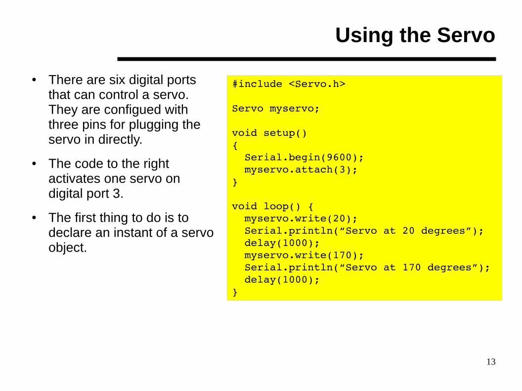
● There are six digital ports that can control a servo. They are configued with three pins for plugging the servo in directly.
● The code to the right activates one servo on digital port 3.
● The first thing to do is to declare an instant of a servo object as shown in bold.
● Any word or name can be used.
#include <Servo.h>
Servo myservo;
void setup(){ Serial.begin(9600); myservo.attach(3);}
void loop() { myservo.write(20); Serial.println(“Servo at 20 degrees”); delay(1000); myservo.write(170); Serial.println(“Servo at 170 degrees”); delay(1000);}

11
Using the Servo
● After creating an instance of the Servo, the function attach() is used to assign the digital pin to the Servo object myservo.
● Any of the 6 digital pins can be selected.
#include <Servo.h>
Servo myservo;
void setup(){ Serial.begin(9600); myservo.attach(3);}
void loop() { myservo.write(20); Serial.println(“Servo at 20 degrees”); delay(1000); myservo.write(170); Serial.println(“Servo at 170 degrees”); delay(1000);}

12
Using the Servo
● To control the servo and set it to a specific angle, the write() function is called.
● The argument passed is the angle in degrees.
● Connect the second servo to the processor board. Pick any of the five remaining digital ports. Add to the code to the right all that is needed to control the second servo. Make up your own Servo instance name.
● Remember all programming is case sensitive.
#include <Servo.h>
Servo myservo;
void setup(){ Serial.begin(9600); myservo.attach(3);}
void loop() { myservo.write(20); Serial.println(“Servo at 20 degrees”); delay(1000); myservo.write(170); Serial.println(“Servo at 170 degrees”); delay(1000);}
13
Using the Servo
● There are six digital ports that can control a servo. They are configued with three pins for plugging the servo in directly.
● The code to the right activates one servo on digital port 3.
● The first thing to do is to declare an instant of a servo object.
#include <Servo.h>
Servo myservo;
void setup(){ Serial.begin(9600); myservo.attach(3);}
void loop() { myservo.write(20); Serial.println(“Servo at 20 degrees”); delay(1000); myservo.write(170); Serial.println(“Servo at 170 degrees”); delay(1000);}

14
Assembly
● Insert the servo into the base servo mounting plate.
● Secure with two ¼ inch 4-40 screws and Kep-nuts.

15
Assembly
● Attach the right angle brackets as shown. Use the larger holes in the bracket and secure with a nut.

16
Assembly
● Take a servo horn and align it's center hole with the larger hole on the arm. There are two smaller holes on either side of the larger one.
● Secure the horn with the tiny sheet metal screws. They are the smallest pointy screws.
● Be careful with handling the arm so fingers do not get poked.
Servo Horn
Larger hole

17
Assembly
● Take the three gripper parts. Peel the protective paper off of both sides of each part.
Gripper Body
Finger
Link
Gripper Parts withProtective Paper

18
Assembly
● Secure both standoffs to the gripper body with ¼ inch 4-40 screws.
19
Assembly
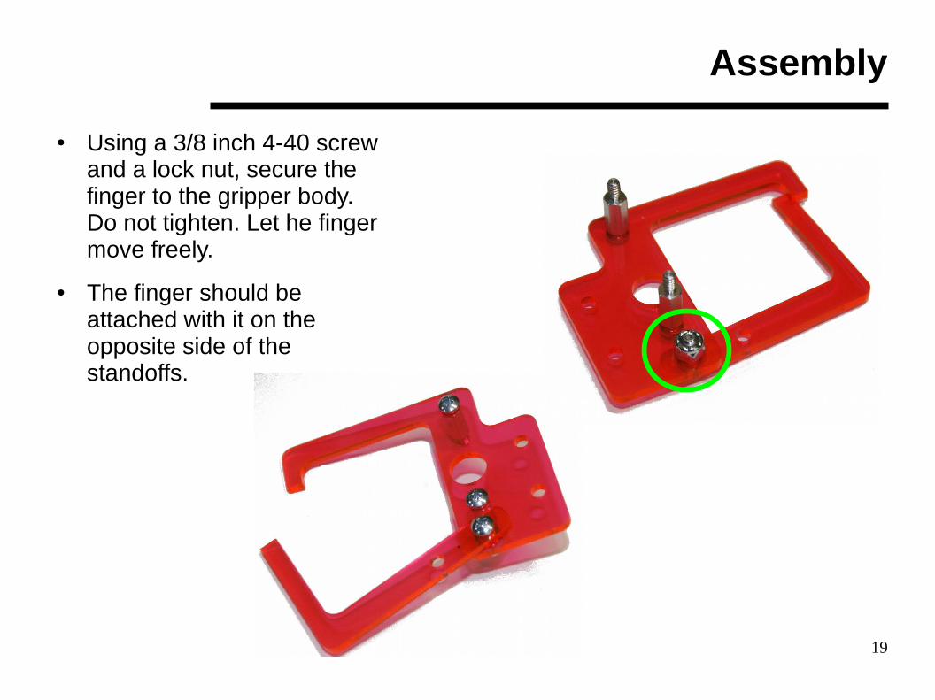
● Using a 3/8 inch 4-40 screw and a lock nut, secure the finger to the gripper body. Do not tighten. Let he finger move freely.
● The finger should be attached with it on the opposite side of the standoffs.

20
Assembly
● Secure the link to the finger as shown. The link should be mounted on the top side so it is at the same plane as the gripper body.
● Secure with a 3/8 inch 4-40 screw and lock nut. Do not tighten. The link should be loose.
● Over tightening the screws can break the plastic parts.

21
Assembly
● Mount the servo onto the standoffs. It will mount only one way. The servo spline must be aligned with the hole in the gripper body.

22
Assembly
● Take the servo horn and insert it onto the servo spline.
23
Assembly
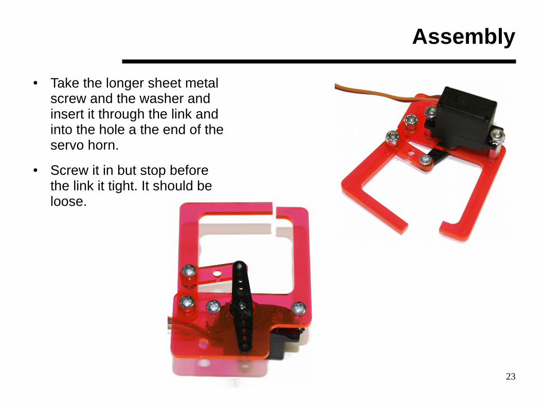
● Take the longer sheet metal screw and the washer and insert it through the link and into the hole a the end of the servo horn.
● Screw it in but stop before the link it tight. It should be loose.

24
Assembly
● Mount the base servo as shown.
● Secure to the rover using two 3/16 inch 4-40 screws from underneath.

25
Assembly
● Take a right angle bracket and mount it to the arm using the larger hole in the bracket.
● Secure the bracket with a ¼ inch 4-40 screw and Kep nut.
● Then secure the gripper assembly to the arm using a 3/16 inch 4-40 screw.

26
Assembly
● Now, mount the arm to the servo by pressing the horn on the arm into the base servo spline.
● Once everything is mounted, connect the base servo to the digital port 3.
● Connect the gripper servo to digital port 5.
● Remember the orientation of the connectors for the servos.
– Brown wire should be closest to the edge of the processor board.
27
Adjustments
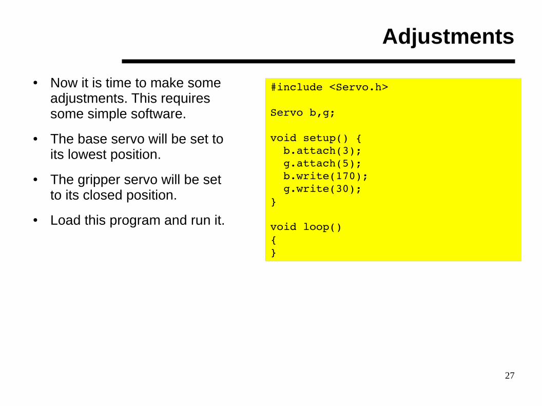
● Now it is time to make some adjustments. This requires some simple software.
● The base servo will be set to its lowest position.
● The gripper servo will be set to its closed position.
● Load this program and run it.
#include <Servo.h>
Servo b,g;
void setup() { b.attach(3); g.attach(5); b.write(170); g.write(30);}
void loop(){}

28
Adjustments
● When the program runs, the two servos will move to the extreme positions.
● Remove the arm from the base servo and reattach it so the gripper is closer to the ground.
● Carefully pull the gripper servo horn off and adjust the finger so it touches the gripper body tip.
● Press the horn back in. This is the closed position.
● Turn power off and secure the horns to the servos with the small black screws that came with the servos.
● This completes the assembly.
#include <Servo.h>
Servo b,g;
void setup() { b.attach(3); g.attach(5); b.write(170); g.write(30);}
void loop(){}

29
Controlling the Robotic Arm
● In this section, the software from the WiFi lesson will be used as the starting point. The WiFi lesson software has the basic structure for adding the gripper controls.
● There are four actions that need to be added.
– Move the robotic arm up
– Move the robotic arm down
– Open the gripper
– Close the gripper
● Just like the motion commands, the robotic arm commands can be single letters.
– The move up command will be A
– The move down command will be Z
– The open gripper command will be D
– The close gripper command will be X.

30
Controlling the Robotic Arm
● Next is to figure out how to control the position of the robotic arm servos.
● One way is to have two variables that maintain the position of the servos. When a command is received, the value in the variable will be adjusted and the servo position will be updated.
● The flow chart to the right shows all the decisions and actions.
ReceiveCommand
Up? Down? Open? Close?
ReduceAngle
on ArmServo
IncreaseAngle
on ArmServo
ReduceAngle
on GripperServo
IncreaseAngle
on GripperServo
UpdateArm
Servo
UpdateArm
Servo
UpdateGripperServo
UpdateGripperServo

31
Arduino Programming
● In this section, the code for the Rover needs to be updated to control both servos.
● Edit the program that includes the WiFi remote control software.
● Include the library Servo just like it was done earlier.
#include <stensat_rover.h>#include <Servo.h>
Stensat_Rover rover;
void setup(){ Serial.begin(9600); rover.init_WiFi(“robot”,80); rover.begin();}
Not all code shown. Only the top portion

32
Arduino Programming
● Next, create two servo objects since there are two servos.
● One will be called base. This is the servo that is mounted to the rover.
● The second server will be called gripper since it controls the gripper.
#include <stensat_rover.h>#include <Servo.h>
Stensat_Rover rover;
Servo base;Servo gripper;
void setup(){ Serial.begin(9600); rover.init_WiFi(“robot”,80); rover.begin();}

33
Arduino Programming
● A variable for each servo will be declared. The purpose of the variables is to keep track of the position of the servos.
● The variables are initialized in the set up function so the servos are set to a known position at power up.
#include <stensat_rover.h>#include <Servo.h>
Stensat_Rover rover;
Servo base;Servo gripper;
int pos_base, pos_grip;
void setup(){ Serial.begin(9600); rover.init_WiFi(“robot”,80); rover.begin(); pos_base = 90; pos_grip = 90;}

34
Arduino Programming
● Next is to initialize the servos.
● First, the object names are attached to the physical port. base is attached to digital port 3. gripper is attached to digital port 5.
● Next, the servos are set to the position specified by the variables.
● This takes care of setting up the servos.
#include <stensat_rover.h>#include <Servo.h>
Stensat_Rover rover;
Servo base;Servo gripper;
int pos_base, pos_grip;
void setup(){ Serial.begin(9600); rover.init_WiFi(“robot”,80); rover.begin(); pos_base = 90; pos_grip = 90; base.attach(3); gripper.attach(5); base.write(pos_base); gripper.write(pos_gripper);}

35
Arduino Programming
● Next is to update the loop portion of the code.
● Four commands will be added to the switch() which is used now to determine the motion of the rover.
● Four letters will be selected to control the motion of the robotic arm.
– A will be move base up.
– Z will be move base down.
– D will be open gripper.
– X will be close gripper.
void loop(){ char buf[100]; if(Serial.available() > 0) { int err = Serial.find(“+IPD”); if(err == TRUE) { Serial.find(“:”); i = Serial.readBytesUntil(0x0a,buf,100); switch(buf[0]) { case 'F' : forward(); break; case 'B' : reverse(); break; case 'L' : left(); break; case 'R' : right(); break; case 'S' : halt(); break; } } }}
Only second portion of code shown

36
Arduino Programming
● The commands will be added to the switch()
● First will be moving the base servo up. In order to move the servo up, the pos_base variable value needs to be decreased.
● It is decremented by 2 which moves the servo up 2 degrees at a time.
void loop(){ char buf[100]; if(Serial.available() > 0) { int err = Serial.find(“+IPD”); if(err == TRUE) { Serial.find(“:”); i = Serial.readBytesUntil(0x0a,buf,100); switch(buf[0]) { case 'F' : forward(); break; case 'B' : reverse(); break; case 'L' : left(); break; case 'R' : right(); break; case 'S' : halt(); break; case 'A' : pos_base = pos_base – 2; } } }}

37
Arduino Programming
● If the command is allowed to execute any time, pos_base variable will become negative and the servo cannot handle that. The value must be checked to make sure it does not go beyond the limit of the servo or beyond a desired position.
● Let's pick 30 degrees as the limit to move up.
● If the variable goes below 30, the variable is reset to 30. This stops the upward motion.
void loop(){ char buf[100]; if(Serial.available() > 0) { int err = Serial.find(“+IPD”); if(err == TRUE) { Serial.find(“:”); i = Serial.readBytesUntil(0x0a,buf,100); switch(buf[0]) { case 'F' : forward(); break; case 'B' : reverse(); break; case 'L' : left(); break; case 'R' : right(); break; case 'S' : halt(); break; case 'A' : pos_base = pos_base – 2;
if(pos_base < 30) pos_base = 30; } } }}

38
Arduino Programming
● Now that the variable pos_base has been updated, it is time to set the servo to the new position.
● base.write() sets the new position.
● break causes the program to get out of the switch() operation so no other code is executed.
void loop(){ char buf[100]; if(Serial.available() > 0) { int err = Serial.find(“+IPD”); if(err == TRUE) { Serial.find(“:”); i = Serial.readBytesUntil(0x0a,buf,100); switch(buf[0]) { case 'F' : forward(); break; case 'B' : reverse(); break; case 'L' : left(); break; case 'R' : right(); break; case 'S' : halt(); break; case 'A' : pos_base = pos_base – 2;
if(pos_base < 30) pos_base = 30; base.write(pos_base);
break; } } }}

39
Arduino Programming
● Downward motion of the base servo is accomplished by adding 2 to the pos_base variable.
● The command Z is used to move the base servo down.
● The limit is set to 170 and the check is to make sure the variable is not greater than 170.
● Upload the code to the rover. Remember to disconnect the WiFi power wire to upload.
● Reconnect and run the program. After the WiFi module has been configured, the base servo should move.
void loop(){ char buf[100]; if(Serial.available() > 0) { int err = Serial.find(“+IPD”); if(err == TRUE) { Serial.find(“:”); i = Serial.readBytesUntil(0x0a,buf,100); switch(buf[0]) { case 'F' : forward(); break; case 'B' : reverse(); break; case 'L' : left(); break; case 'R' : right(); break; case 'S' : halt(); break; case 'A' : pos_base = pos_base – 2;
if(pos_base < 30) pos_base = 30; base.write(pos_base);
break; case 'Z' : pos_base = pos_base + 2;
if(pos_base > 170) pos_base = 170; base.write(pos_base); break;
} } }}

40
Processing Programming
● Commands need to be added to the processing program.
● Keyboard keys A and Z will be used to move the robotic arm up and down.
● Keyboard keys S and X will be used to open and close the gripper.
● The program to the right is the current state.
import processing.net.*;
Client c;
void setup(){ size(800,600); c = new Client(this,”192.168.4.1”,80);}
void keyPressed(){ if(keyCode == UP) c.write(“F”); else if(keyCode == LEFT) c.write(“L”); else if(keyCode == RIGHT) c.write(“R”); else if(keyCode == DOWN) c.write(“B”);}
void keyReleased(){ c.write(“S”);}
void draw(){}

41
Processing Programming
● The function keyPressed() will be updated. None of the other code will be modified.
● The first added code is to move the robotic arm up. It is assumed the CAPS lock is not active so the program needs to look for lower case letters.
void keyPressed(){ if(keyCode == UP) c.write(“F”); else if(keyCode == LEFT) c.write(“L”); else if(keyCode == RIGHT) c.write(“R”); else if(keyCode == DOWN) c.write(“B”); if(key == 'a') c.write(“A”);}
void keyReleased(){ c.write(“S”);}
void draw(){}

42
Processing Programming
● The next line added is to move the robotic arm down.
● Turn on the rover.
● Connect the laptop to the rover's WiFi access point.
● Run the processing program.
● Press the a and z keys. The robotic arm should move up and down.
void keyPressed(){ if(keyCode == UP) c.write(“F”); else if(keyCode == LEFT) c.write(“L”); else if(keyCode == RIGHT) c.write(“R”); else if(keyCode == DOWN) c.write(“B”); if(key == 'a') c.write(“A”); else if(key == 'z') c.write(“Z”);}
void keyReleased(){ c.write(“S”);}
void draw(){}

43
Making Adjustments
● If the robotic arm does not move down far enough, unscrew the screw on the base servo.
● Pull the arm off and reposition it downward more and press back on to the servo.
● Reinsert the screw.

44
Controlling the Gripper
● It is your turn to write the code to operate the gripper. It will be the same as the base servo code except using the gripper variables and different commands.


