Robotic Control with Kinect Vision Comprehensive Report Arnold Fernandez Victor Fernandez Tom Nguyen Instructor: Janusz Zalewski CEN 4935 Senior Software Engineering Project Florida Gulf Coast University 10501 FGCU Blvd, South Fort Myers, FL 33965-6565 Spring 2013 Draft #2 Submission Date: April 18, 2013
5.1 Test Plan ............................................................................................................................................ 42
5.1.1 Test Items ................................................................................................................................... 42
5.1.3 Test Cases ................................................................................................................................... 43
5.2 Test Results ....................................................................................................................................... 46
5.2.1 Platform and Equipment ............................................................................................................ 46
5.2.2 Test Cases Results ...................................................................................................................... 46
The purpose of this Comprehensive Report document is to explain the requirements and the
design details for a Robotic Control with Kinect Vision software application. The intended
audiences of this document are developers, designers and project managers for operating a robot
with visual data. The product to be developed is a Windows software application that will engage
the Corobot [6], Kinect Vision [5] and an AL5A robotic arm [7].
The software under designinterfaces withfour hardware components,a Kinect motion sensor,
Corobot, a Logitech HD Webcam that is attached to the body of the Corobot, and the AL5A
robotic arm. Furthermore, the software under design interfaces with two different API’s; the
Kinect NUI API and the Phidgets API. The fundamentals reasons that led to the design of the
software were limitations in the hardware devices that interface with the software.
The remainder of this document contains an overall description of the product to be developed
including product perspective, product functions, user characteristics, constraints, assumptions
and dependencies, and specific requirements. In addition, it contains the design details pertaining
to the design views, design viewpoints, design elements, design overlays and design rationale of
the software under design. The team is aware of the IEEE standard for design descriptions [9],
but due to the small size of this project, the standard is followed only to some extent.
2. Requi
2
irements Sp
.1 Product P
2.1.1
This p
motio
Phidg
A diag
shown
The K
help d
reacts
library
Sens
Comm
pecification
Perspective
System Inte
product inter
on sensor NU
gets API.
gram showin
n in Figure 1
Kinect SDK (
developers u
s to real-worl
y interact wi
sorData
Status Fe
mands
erfaces
rfaces with M
UI API, Coro
ng how the c
1.
Figure 1 C
(Figure 2) pr
se the rich fo
ld events. Fi
ith the produ
edback
Image
Microsoft W
obot Phidget
components
Context Dia
rovides a sop
form of Kine
igure 3 show
uct.
V
Execute
e Video Data
Windows 7 Op
ts API, and th
of this produ
agram
phisticated s
ect-based nat
ws how the K
Command
Status Feed
Video Feedback
e Product
perating Sys
he AL5A ro
uct interface
software libr
tural input, w
Kinect and th
ds
dback
k
5 | P
stem, the Kin
obotic arm
e together is
rary and tool
which senses
he software
a g e
nect
ls to
s and
2.1.2 U
The u
the Ki
attach
User Interfa
user interface
inect IR dep
hed to the Co
Figure 2
Figure 3 Ki
faces
e is a window
th sensor an
orobot’s bod
2 Kinect SD
inect Intera
ws form that
nd the Logite
dy.
K[1]
action[2]
t will provide
ech HD Web
e the user w
bcam C615 (
6 | P
ith images fr
Figure 4)
a g e
from
2.1.3 H
This p
a Kine
the Co
the im
Kinec
The h
Figure
Fi
Hardware I
product requ
ect motion s
orobot (Figu
mages from th
ct IR depth s
hardware dev
e 5.
igure 4 Logi
Interfaces
uires three m
ensor (Figur
ure A2), and
he Logitech
ensor, a com
vices describ
itech HD W
ajor hardwar
re A1), a com
the AL5A ro
HD Webcam
mputer monit
bed above are
Webcam[3]
re componen
mputer moth
obotic arm (
m C615 atta
tor is require
e connected
nts as shown
herboard insi
(Figure A3).
ached to the C
ed.
in a system
7 | P
n in Appendi
ide the body
In order to s
Corobot and
detailed in
a g e
ix 1,
y of
see
d the
8 | P a g e
Figure 5 Physical Diagram
2.1.4 Software Interfaces
The software interfaces required by this product are the respective API’s to
program the Kinect motion sensor, Corobot and AL5A robotic arm.
2.1.5 User Characteristics
The intended user of this product is anyone capable of using a computer.
2.2 Constraints and Assumptions
The product been developed obtains the distance between an object and the Corobot
using the Kinect sensor IR emitter and IR depth sensor (Figure 6). In a similar way as
stated in the previous sentence, the product obtains the distance between and object and
the AL5A robotic arm. Once the distance between an object and the Corobot has been
9 | P a g e
obtained, the Corobot engages its four wheels and tries to get close to the object. When
close, the Corobot stops moving to allow the AL5A to try to pick the object.
It is assumed that this product will be used with a Kinect sensor, an AL5A robotic arm,
and a Corobot whose motherboard has installed a Windows Operating System that
supports the .NET Framework 4.0. Not meeting these assumptions might make the
product inoperable. Furthermore, the Kinect IR emitter shall emit IR rays. The Kinect
depth sensor shall detect the IR emitter IR rays, and detect the depth between an object
and the sensor.
In addition, the following hardware limitations need to be taken into account:
2.2.1 The AL5A robotic arm has an extremely short range distance. An object has
to be very close to the arm in order for the arm to be able to reach it and grab it.
2.2.2 The Kinect sensor has to be connected to an electrical power supply in order
to receive electrical power and provide motion feedback.
2.2.3 The AL5A has to be connected to an electrical power supply in order for the
servos to engage properly.
Figure 6 Kinect Components[4]
10 | P a g e
2.3 Functional Requirements
Due to the constraints the software under design faces, the team decided to change the
functional requirements of the software under design. The new functional requirements
are described in section 3.4 New Requirements.
2.3.1 Input Requirements
2.3.1.1 The product shall accept the depth detected by the Kinect IR depth
sensor.
2.3.1.2 The product shall calculate the distance between and object and the
AL5A robotic arm.
2.3.1.3 The product shall calculate the distance between and object and the
Corobot.
2.3.1.4 The product shall receive video images from the Logitech HD
Webcam C615.
2.3.2 Output Requirements
2.3.2.1 The product shall make the AL5A robotic pick up objects that are
within its reach distance.
2.3.2.2 The product shall make the Corobot move and engage its four
wheels.
2.3.2.3 The product shall display the Kinect depth sensor data.
2.3.2.4 The product shall display the video images received from the
Logitech HD Webcam C615.
2.4 Non-Functional Requirements
2.4.1 Reliability
2.4.1.1 The product shall perform all its functions while the Kinect, the
Corobot and the AL5A robotic arm are properly powered.
11 | P a g e
2.4.2 Availability
2.4.2.1 The product shall not have any availability issues as long as all the
hardware components (Kinect, Corobot, and AL5A robotic arm) are
present and the source code of the software application is available.
2.4.3 Security
2.4.3.1 The product does not rely on an Internet connection thus it shall
not have any security constraints.
2.4.4 Maintainability
2.4.4.1 In order to provide better maintenance of our software, a brief user
guide shall be provided to explain product’s functionalities and how to
operate these functionalities within Windows 7 OS.
2.4.5 Portability
2.4.5.1 The product shall be able to be ported to any Windows OS PC that
supports the .NET Framework 4.0.
2.5 Product Operation
In order for the product to operate correctly, the Corobot, the Kinect, the AL5A, and the
Logitech Webcam have to be properly powered and turned on. When all the hardware
devices are turned on and the product is executed, the Kinect sensor obtains the depth and
color data streams. Next, the Logitech Webcam obtains video image data stream. Once
the data streams are obtained, the product displays the data streams. This is followed by
the product calculating the distance between and object and the Corobot and moving the
Corobot close to the object. After the Corobot is close to the object, the AL5A engages
and tries to pick up the object.
The product operation described above is detailed in Figure 7.
12 | P a g e
Figure 7 Product Operation Flowchart
13 | P a g e
3. Design Description
The software under design is composed of a main class that interfaces with two different APIs;
the Kinect NUI API and the Phidgets API. The Kinect NUI API allows the software under
design to interface with the Kinect sensor and obtain the Kinect’s sensor color and depth data
streams. The Phidgets API allows the software under design to interface with the AL5A robotic
arm and Corobot to control their respective servo motors. Figure 8 shows a preliminary class
diagram of the software under design.
14 | P a g e
Figure 8 Class Diagram
The softw
stream, th
status via
command
of what d
robotic a
as well a
When the
is called,
displays
displayed
chckBox
myKinec
captured
ware under d
he Logitech
a a Graphica
ds to tilt the
data he/she w
arm or Corob
s the Logitec
e user enable
this method
each color fr
d in a similar
xDepthSenso
ctSensor_De
by the Kine
design displa
HD Webcam
al User Interf
angle motor
wants display
bot. The user
ch HD Webc
es the Kinec
d then fires m
frame capture
r manner. W
or_Checked i
epthFrameRe
ect’s depth se
ays the Kine
m video stre
face (GUI). I
r of the Kine
yed on the G
r can enable
cam video st
ct’s color dat
myKinectSen
ed by the Ki
When the user
is called, thi
eady event h
ensor.
Figure
ct’s color da
am, and the
In addition,
ect. Furtherm
GUI, and wh
or disable th
tream. Figur
ta stream, the
nsor_ColorF
inect’s rgb c
r enables the
s method the
handler which
e 9 GUI Ske
ata stream, th
AL5A robo
the GUI allo
more, the GU
ether to enga
he Kinect’s c
re 9 shows a
e method ch
FrameReady
amera. The K
e Kinect’s de
en fires
h then displa
tch
he Kinect’s d
tic arm and
ows the user
UI lets the us
age or disen
color and de
sketch of th
hckBoxRgbC
event handl
Kinect’s dep
epth data str
ays each dep
15 | P
depth data
Corobot eng
r to send
ser have cont
ngage the AL
epth data stre
he GUI.
Camera_Che
ler which the
pth data strea
eam, the me
pth frame
a g e
gaged
trol
L5A
eam,
ecked
en
am is
ethod
3
T
d
se
d
M
w
pr
.1 Design C
The Kinect se
esign constr
ensor is 57.5
egrees to + 2
Moreover, the
within the ran
ractical limi
Constraints
ensor, with w
raints. The K
5 degrees. Th
27 degrees (F
Fi
e Kinect’s d
nge of 0.8 m
ts are from 1
which the so
Kinect’s horiz
he vertical v
Figure 10).
gure 10 Kin
epth sensor
meters up to 8
1.2 meters to
oftware unde
zontal view
iew angle is
nect View A
can only cal
8 meters awa
o 3.5 meters
r design inte
angle for the
43.5 with a
Angles [10]
lculate the di
ay from the K
(Figure 11).
erfaces, pres
e rgb camera
chance to ti
istance to ob
Kinect. In ad
.
16 | P
ents several
a and the dep
ilt the angle
bjects that ar
ddition, the
a g e
pth
-27
re
17 | P a g e
Figure 11 Kinect Practical Limits [10]
If an object is closer than 0.8 meters or farther than 8 meters, the Kinect cannot calculate
the distance to the object and the distance returned is 0 (Figure 12). This means, that in
practice, the AL5A would never be able to pick up an object because of its short reach
distance and the fact that it is impossible to know if an object is extremely close or very
far away from it (Figure 13).
18 | P a g e
Figure 12 Kinect Depth Sensor Range Limitation
Figure 13 AL5A Reach Distance
19 | P a g e
3.2 Program Control Flow
The Kinect’s rgb camera and the Logitech HD Webcam are used only to provide the user
with scene feedback. What makes the Corobot and the AL5A robotic arm interact with
objects is the Kinect’s depth sensor. When the Kinect’s depth sensor is enabled, the depth
data stream is obtained. After the depth data stream has been obtained, the distance in
millimeters from the Kinect to an object is calculated. In addition, the relative position of
the object in relation with the Kinect is calculated. When all this calculations have been
made, the software under design waits until the user enables either the Corobot or the
AL5A robotic arm.
If the AL5A is enabled, the software under design gets the distance to the object and the
AL5A will try to throw an item to the object. If The Corobot is enabled, the software
under design checks if an obstacle is in the Corobot’s moving path. If it is, the Corobot
tries to move around the obstacle, otherwise it will keep moving forward. Figure 14 show
a detailed dynamic representation of the software under design.
20 | P a g e
Figure 14 Program
21 | P a g e
3.3 Detailed Design
In order to display the Kinect’s color data stream and the Kinect’s depth data stream, the
Kinect has to be powered and connected to the Corobot. An example pseudocode of how
the software under design determines if the Kinect is powered and connected is shown in
Figure 15.
if (the Kinect != null) { if (the Kinect status is disconnected) { Display message } elseif (the Kinect status is not powered) { Display message } elseif (the Kinect status is connected) { Initialize the Kinect } } else { Display error message. No Kinect detected } }
Figure 15 Kinect Status
Once the software under design determined the status of the Kinect, the Kinect is
initialized. Initializing the Kinect means the event handlers associated with the color and
depth image frames are created and the Kinect is started.
22 | P a g e
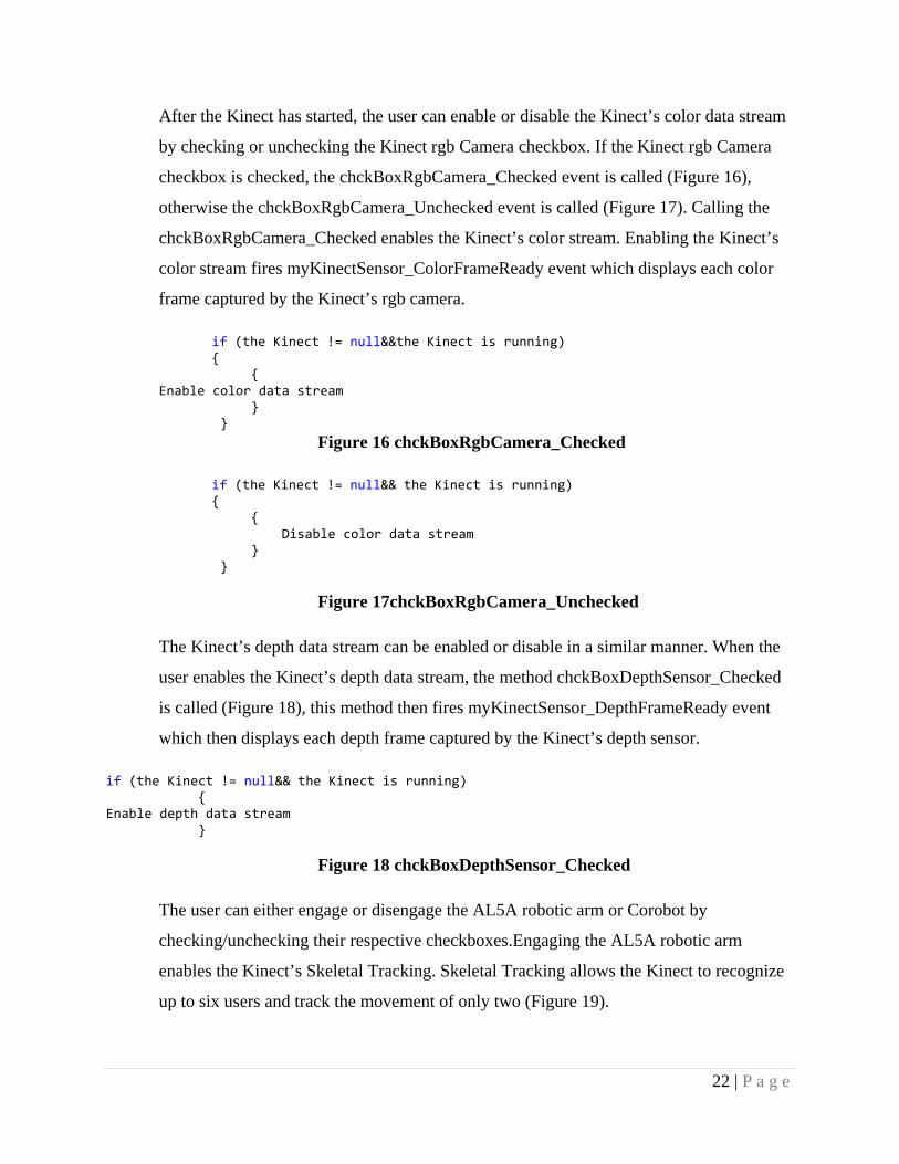
After the Kinect has started, the user can enable or disable the Kinect’s color data stream
by checking or unchecking the Kinect rgb Camera checkbox. If the Kinect rgb Camera
checkbox is checked, the chckBoxRgbCamera_Checked event is called (Figure 16),
otherwise the chckBoxRgbCamera_Unchecked event is called (Figure 17). Calling the
chckBoxRgbCamera_Checked enables the Kinect’s color stream. Enabling the Kinect’s
color stream fires myKinectSensor_ColorFrameReady event which displays each color
frame captured by the Kinect’s rgb camera.
if (the Kinect != null&&the Kinect is running) {
{ Enable color data stream } }
Figure 16 chckBoxRgbCamera_Checked
if (the Kinect != null&& the Kinect is running) {
{ Disable color data stream } }
Figure 17chckBoxRgbCamera_Unchecked
The Kinect’s depth data stream can be enabled or disable in a similar manner. When the
user enables the Kinect’s depth data stream, the method chckBoxDepthSensor_Checked
is called (Figure 18), this method then fires myKinectSensor_DepthFrameReady event
which then displays each depth frame captured by the Kinect’s depth sensor.
if (the Kinect != null&& the Kinect is running) { Enable depth data stream }
Figure 18 chckBoxDepthSensor_Checked
The user can either engage or disengage the AL5A robotic arm or Corobot by
checking/unchecking their respective checkboxes.Engaging the AL5A robotic arm
enables the Kinect’s Skeletal Tracking. Skeletal Tracking allows the Kinect to recognize
up to six users and track the movement of only two (Figure 19).
23 | P a g e
Figure 19 Skeletal Tracking Joints [11]
Figure 19.1 Skeletal Tracking Practical Range [11]
24 | P a g e
Figure 20 shows an example of how Skeletal Tracking is enabled.
if (the robotic arm != null&&the robotic arm is attached) { if (the Kinect skeletal stream is not enable) { Enable skeletal stream } } else { if (the Kinect skeletal stream is enable) { Disable the skeletal stream } }
Figure 20 Enabling Skeletal Tracking
Once the AL5A is engaged and the Kinect’s Skeletal Tracking is enabled, the software
under design calculates the user’s position. When the user’s position is known, the AL5A
robotic arm is able to pick up an object and throw the object in the direction of the user’s
position. Engaging the Corobot allows the user to control it. The user can send commands
to the software under design to either move the Corobot forward, backward, left or right.
3.4New Requirements
Due to the constraints the software under design faces, the team decided to change the
functional requirements of the software under design. The new functional requirements
are as follow:
3.4.1 Functional Requirements
3.4.1.1 Input Requirements
3.4.1.1.1 The product shall obtain the depth detected by the Kinect
IR depth sensor.
3.4.1.1.2 The product shall obtain the hip position of a user.
3.4.1.1.3 The product shall accept voice commands to move the
Corobot.
3.4.1.1.4 The product shall receive video images from the Logitech
HD Webcam C615.
25 | P a g e
3.4.1.2 Output Requirements
3.4.1.2.1 The product shall make the AL5A robotic pick up an
object.
3.4.1.2.2 The product shall make the AL5A throw the object in the
direction of where the user is standing.
3.4.1.2.3 The product shall make the Corobot move and engage its
four wheels.
3.4.1.2.4 The product shall display the Kinect depth sensor data as
a bitmap image.
3.4.1.2.5 The product shall display the video images received from
the Logitech HD Webcam C615.
26 | P a g e
4. Implementation
The software application designed consists of 3 C Sharp classes. These classes are briefly
described below:
1. MainWindowhandles all the events associated with the Graphical User Interface. In
addition, it contains all the methods necessary to interface with the Kinect, the Corobot
and the AL5A robotic arm.
2. Servo is used to store data values (acceleration, engaged status, maximum and minimum
position, actual position, and velocity) pertaining to each of the servos of the AL5A
robotic arm.
3. CalibrationWindow contains all the methods necessary to save and load the AL5A
robotic arm calibrations.
The main entry point of the software designed is the MainWindow class. The MainWindow class
initializes all the components to build the Graphical User Interface (Figure 21).
Figure 28 Graphical User Interface
27 | P a g e
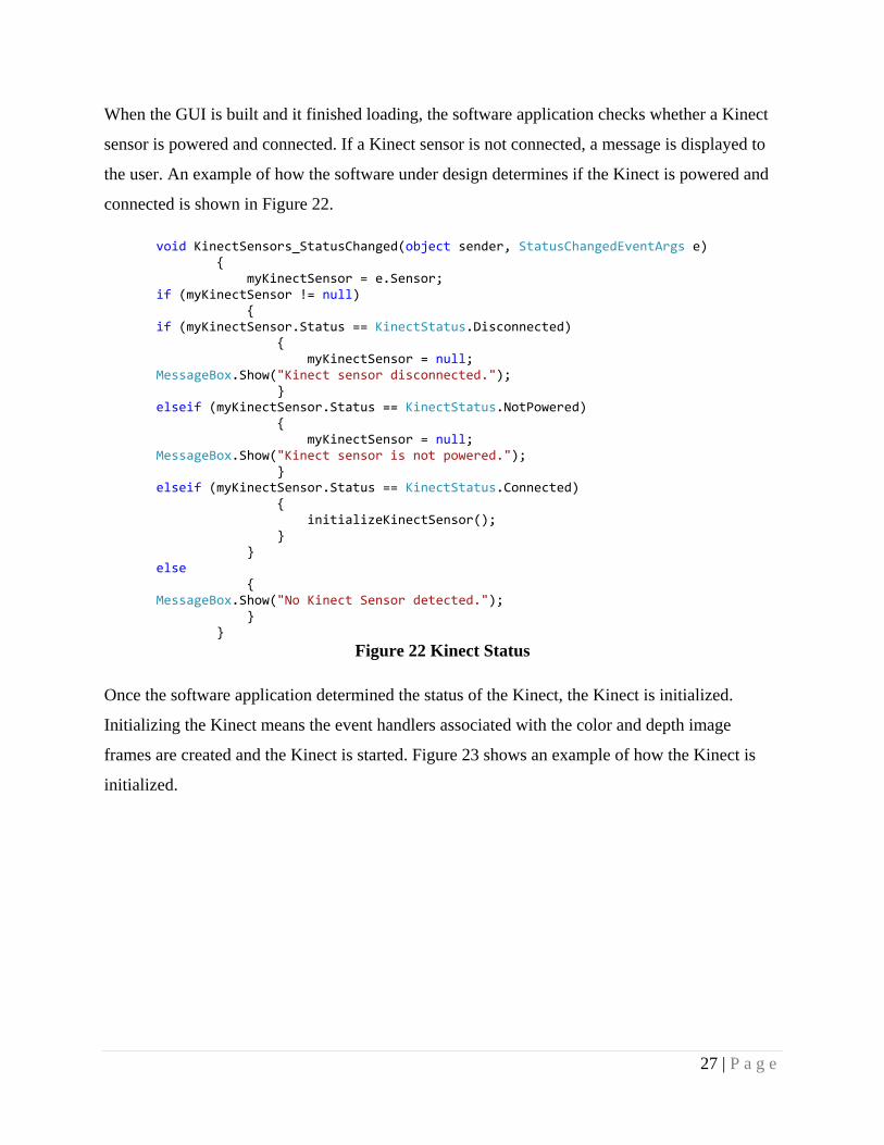
When the GUI is built and it finished loading, the software application checks whether a Kinect
sensor is powered and connected. If a Kinect sensor is not connected, a message is displayed to
the user. An example of how the software under design determines if the Kinect is powered and
Once the software application determined the status of the Kinect, the Kinect is initialized.
Initializing the Kinect means the event handlers associated with the color and depth image
frames are created and the Kinect is started. Figure 23 shows an example of how the Kinect is
initialized.
28 | P a g e
privatevoid initializeKinectSensor() { // check if at least one Kinect is connected if (KinectSensor.KinectSensors.Count > 0) { // set myKinectSensor equal to the first Kinect sensor myKinectSensor = KinectSensor.KinectSensors[0]; // if the Kinect status is connected if (myKinectSensor.Status == KinectStatus.Connected) { // get the Kinect's status and id txtblStatus.Text = myKinectSensor.Status.ToString(); txtblId.Text = myKinectSensor.UniqueKinectId; try { // color and depth image frames event handlers myKinectSensor.ColorFrameReady += newEventHandler<ColorImageFrameReadyEventArgs>(myKinectSensor_ColorFrameReady); myKinectSensor.DepthFrameReady += newEventHandler<DepthImageFrameReadyEventArgs>(myKinectSensor_DepthFrameReady); // start the Kinect myKinectSensor.Start(); // setup speech recognizer setupKinectSpeechRecognizer(); lblCurrentAngle.Content = myKinectSensor.ElevationAngle.ToString(); MessageBox.Show("Kinect Sensor connected."); } catch (System.IO.IOException) { MessageBox.Show("Could not start the Kinect Sensor. Another program might be using it."); stopKinect(); } } } // no Kinect detected else { MessageBox.Show("No Kinect Sensor detected."); //this.Close(); } }
Figure 23 Kinect Initialization
29 | P a g e
After the Kinect has started, the user can enable or disable the Kinect’s color data stream and
depth data stream by checking or unchecking their respective checkboxes (Figure 24).
Figure 24 Enable/Disable RGB Camera and Depth Sensor
An example of how the Kinect’s color data stream is enabled and disabled is show in Figure 25.
Similar methods are used to enable and disable the Kinect’s depth data stream. Enabling the
color data stream or depth data stream fires the Kinect’s frame ready event handlers which
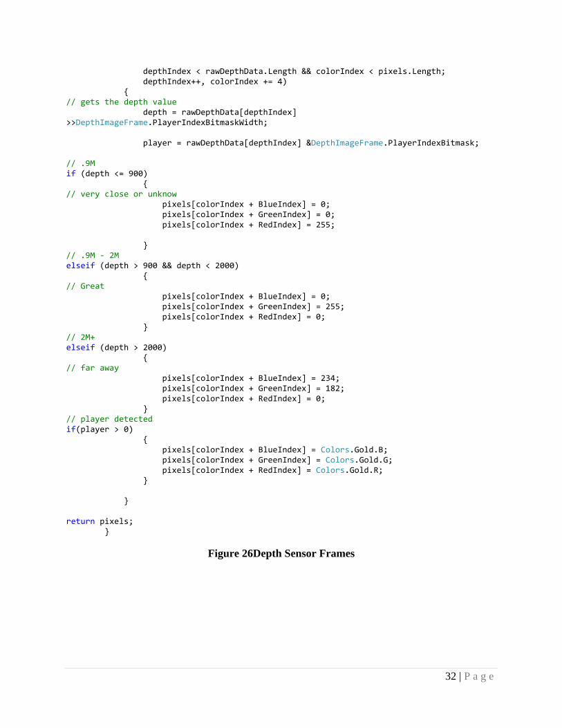
obtains the frames captured by the rgb camera or depth sensor. An example of how the depth’s
senor frames are obtained and displayed in the GUI is show in Figure 26.
// Get Depth sensor frame pixel data privatebyte[] GenerateColoredBytes(DepthImageFrame depthFrame) { int depth; int player; // get the raw data from kinect with the depth for every pixel short[] rawDepthData = newshort[depthFrame.PixelDataLength]; depthFrame.CopyPixelDataTo(rawDepthData); Byte[] pixels = newbyte[depthFrame.Height * depthFrame.Width * 4]; // RGB index positions constint BlueIndex = 0; constint GreenIndex = 1; constint RedIndex = 2; // loop through all distances // pick a RGB color based on distance for (int depthIndex = 0, colorIndex = 0;
advServo.Attach += new Phidgets.Events.AttachEventHandler(advServo_Attach); advServo.Detach += new Phidgets.Events.DetachEventHandler(advServo_Detach);
advServo.Error += new Phidgets.Events.ErrorEventHandler(advServo_Error); // hook the phidget specific event handlers advServo.PositionChange += new Phidgets.Events.PositionChangeEventHandler (advServo_PositionChange); advServo.VelocityChange += new Phidgets.Events.VelocityChangeEventHandler (advServo_VelocityChange); } catch (Exception ex) { MessageBox.Show(“Error: “ + ex.Message); } }
// At Velocity = 30, and robot is moving (static friction force = 0), robot can move at ~0.6m/s
// Safe start. Slowly accelerate for (i = 0.00; i < ‐initVel; i‐‐) { // Allow motor to apply its force before sending another value Thread.Sleep(100); motorControl.motors[0].Velocity = i; motorControl.motors[1].Velocity = i; } // Continue to accelerate to maximum Velocity motorControl.motors[0].Velocity = ‐maxVel; motorControl.motors[1].Velocity = ‐maxVel; // Distance = Velocity * Time. int coeff = 100000; int sleepTime = (int)(coeff * distance / maxVel); Thread.Sleep(sleepTime); /* Safe stop. Slowly decelerate */ for (; i <= 0; i++) { // Allow motor to apply its force before sending another value Thread.Sleep(100); motorControl.motors[0].Velocity = i; motorControl.motors[1].Velocity = i; } } else { selectNegativeSound(); } } catch (Exception ex) { MessageBox.Show("Error: " + ex.Message); } }
Figure 36 Move Corobot Backwards
42 | P a g e
5. Testing
5.1 Test Plan
The objective of software testing will be to find and fix bugs in the software, and
to assure that the software meets all the requirements. Each part of the software
will be tested rigorously according to what task it should accomplish, and this task
must be performed correctly and without errors.
The hardware used to test the software will be a computer with Windows 7,
Kinect sensor, and Corobot. The testers of the software will be each member of
the team. The Test environment will be the computer science lab in Holmes Hall.
5.1.1 Test Items
The test items included in this plan are the following functional requirement items
from the Requirement Specification document [8]:
The product shall obtain the depth detected by the Kinect IR depth sensor.
The product shall obtain the hip position of a user.
The product shall accept voice commands to move the Corobot.
The product shall receive video images from the Logitech HD Webcam
C615.
The product shall make the AL5A robotic pick up an object.
The product shall make the AL5A throw the object in the direction of
where the user is standing.
The product shall make the Corobot move and engage its four wheels.
The product shall display the Kinect depth sensor data as a bitmap image.
5.1.2 Approach
The program will be debugged using Visual Studio 2010, and each member of the
team will manually test each item described in section 1.2 Test Items.
43 | P a g e
5.1.3 Test Cases
Test Case No 1. Requirement 3.4.1.1.1
Objective: Test that the depth of valid frames is obtained
Test Description: Run depth sensor for 1 second
Expected Results: A message with the frame’s depth data is displayed on the console screen and
a bitmap image representing the depth of each pixel is displayed on the GUI
Test Case No 2. Requirement 3.4.1.1.2
Objective: Test that the hip position of a person standing in front of the Kinect sensor is obtained
Test Description: One member of the team will stand in front of the Kinect at a distance where
his/her full body is visible to the Kinect
Expected Results: A message with the person’s hip position is displayed on the console screen
Test Case No 3. Requirement 3.4.1.1.2
Objective: Test that the product does not obtain a person’s hip position
Test Description: One member of the team will stand in front of the Kinect at a distance where
only part or none of his/her body is visible
Expected Results: Voice feedback saying “Sorry I could not get your position”
44 | P a g e
Test Case No 4. Requirement 3.4.1.1.3
Objective: Test that the voice command to move Corobot forward is correctly processed
Test Description: One member of the team will say “forward” loud and clear
Expected Results: The Corobot moves forward 0.5 meters
Test Case No 5. Requirement 3.4.1.1.3
Objective: Test that the voice command to move Corobot backward is correctly processed
Test Description: One member of the team will say “back” loud and clear
Expected Results: The Corobot moves backward 0.5 meters
Test Case No 6. Requirement 3.4.1.1.3
Objective: Test that the voice command to rotate Corobot to the right is correctly processed
Test Description: One member of the team will say “right” loud and clear
Expected Results: The Corobot rotates 90° degrees to the right
45 | P a g e
Test Case No 7. Requirement 3.4.1.1.3
Objective: Test that the voice command to rotate Corobot to the left is correctly processed
Test Description: One member of the team will say “left” loud and clear
Expected Results: The Corobot rotates 90° degrees to the left
Test Case No 8. Requirement 3.4.1.1.4
Objective: Test that the Logitech HD camera stream is obtained and displayed on the GUI
Test Description: Use VLC to stream the HD camera
Expected Results: The Logitech HD camera is displayed on the GUI
Test Case No 9. Requirement 3.4.1.2.1 and 3.4.1.2.2
Objective: Test that the AL5A robotic arm is able to pick up an object and throw it in the
direction of a person standing in front of the Kinect
Test Description: One member of the team will stand in front of the Kinect at a distance where
his/her full body is visible to the Kinect and say “throw” loud and clear
Expected Results: The robotic arm should pick up the object and throw it in the direction of
where the person is standing
46 | P a g e
5.2 Test Results
5.2.1 Platform and Equipment
The tests were executed on April 5, 2013, in the computer science lab in Holmes
Hall. The platform and equipment used to perform the test were the following:
Microsoft Windows 7
Visual Studio 2010
Microsoft Kinect Sensor
Logitech HD camera
AL5A robotic arm
Corobot
VLC media player
5.2.2 Test Cases Results
Test Case No 1. Requirement 3.4.1.1.1
Applied input: Depth data stream captured by the Kinect Sensor
Output: An image representing the depth of each pixel was displayed on the GUI
Criteria: pass
Test Case No 2. Requirement 3.4.1.1.2
Applied input: Skeletal joins data
Output: A message with the person’s hip position was displayed on the console screen
Criteria: pass
47 | P a g e
Test Case No 4. Requirement 3.4.1.1.3
Applied input: Voice command “forward”
Output: The Corobot moved forward 0.5 meters
Criteria: pass
Test Case No 5. Requirement 3.4.1.1.3
Applied input: Voice command “back”
Output: The Corobot moved backward 0.5 meters
Criteria: pass
Test Case No 6. Requirement 3.4.1.1.3
Applied input: Voice command “right”
Output: The Corobot rotated 90° degrees to the right
Criteria: pass
Test Case No 7. Requirement 3.4.1.1.3
Applied input: Voice command “left”
Output: The Corobot rotated 90° degrees to the left
Criteria: pass
48 | P a g e
Test Case No 8. Requirement 3.4.1.1.4
Applied input: Logitech HD camera video stream from VLC media player
Output: The Logitech HD camera was displayed on the GUI
Criteria: pass
Test Case No 9. Requirement 3.4.1.2.1 and 3.4.1.2.2
Applied input: User’s hip position obtained from the skeletal joins data; voice command
“throw”
Output: The robotic arm picked up the object and threw it in the direction of where the
person was standing
Criteria: pass
After several rigorously tests, no errors were found, and the software meets all its
requirements. However, requirements 3.1.1.1.3 and 3.4.1.2.1 did not meet the expected
results in some occasions because the Kinect sensor is very sensitive to voice commands.
Thus, for better results the noise in the room should be minimal, and the voice command
should be said loud and clear very close to the Kinect Sensor.
49 | P a g e
6. Conclusion
The fundamentals reasons that led the software application to be designed as it is were
limitations in the hardware devices that interface with the software application. The Kinect’s
depth sensor can only calculate the distance to objects that are within the range of 0.8 meters up
to 8 meters away from the Kinect. This means, that in practice, the AL5A would never be able to
pick up an object because of its short reach, and the fact that Kinect is unable to calculate the
distance of objects which are closer than 0.8 meters or farther than 8.0 meters. Due to these
constraints, the team decided to change the requirementsof the software application. The new
requirements are specified in section 3.4 New Requirements.
The software application can be expanded in several ways:
Expand the GUI to allow the user to specify how much distance the Corobot shall move.
Currently the distance is hardcoded to 0.5 meters.
Expand the GUI to allow the user to specify how many degrees the Corobot shall rotate.
Currently the degree is hardcoded to 90 degrees.
Expand the GUI to allow the user to specify the serial number of a PhidgetAdvanceServo
8-Motor Controller. Currently the serial number is hardcoded to 170320.
Add new functionalities to the software application, i.e., track a person with the Kinect
sensor and make the Corobot follow this person. Make the AL5A robotic arm imitate the
body or hand gestures of a person.
Install a portable power supply to the body of the Corobot. The Kinect and the AL5A
robotic arm must be connected to an electrical source in order to operate and receive
The purpose of this review is to to determine if the Software Design Document, produced by the Robotic Control Team, is suitable for its intended needs. This review will be a technical review, which will adhere to the details described in section 5 of the IEEE Std 1028 document [1]. It will confirm and provide evidence of the following:
a) The software product conforms to its specifications b) The software product adheres to regulations, standards, guidelines, plans, and procedures applicable to the project c) Changes to the software product are properly implemented and affect only those system areas identified by the change specification
2. Responsibilities
2.1 Decision maker
This technical review is conducted for Victor Fernandez. Victor is the decision maker of the Robotics Team.
2.2 Review leader
Felipe Velosa is the review leader for this technical review. This review has been conducted in an orderly manner, and met its objectives under the supervision of Felipe.
2.3 Recorder
The recorder for the technical review is James Royal. James has documented all found anomalies, action items, decisions, and recommendations
2.4 Technical staff
The technical staff are James Royal and Felipe Velosa.
2.5 Management staff Dr. Janusz Zalewski is the management staff.
2.6 Customer or user representative None
61 | P a g e
3. Input
a. The objectives of the technical review are to ensure the software product conforms to its specifications and it adheres to standards, guidelines, plans, and procedures. It will also ensure that changes to the software product are properly implemented. b. The software product being examined: Robotic control with Kinect c. Current anomalies or issues for the software product.
1. In practice, the AL5A is unable to pick up an object because of its short reach distance. This is uncompatible with the 3.1.2.1 software design specification which states that the AL5A shall pickup objects within its reach.
2. The kinetic can only detect objects between 0.8 meters and 8 meters. This makes the Kinect unable to calculate the distance to nearby and faraway objects. This is incompatible with the 3.1.1.1, 3.1.1.2, 3.1.1.3 specifications because none of these requirement specifications specify a range of detection for the Kinetic sensor.
3. Specification 3.2.2.1 states that the product shall not have any availablity issues as long as the hardware components are present and source code of the software is available. However, the SDD states that the availability of the Corbot/Robotic direct relationship. If one is in use the other is in standby and vice versa.
e) Documented review procedures:
The recorder has identified existing anomalies. Once identified the review leader and the recorder have referenced the Robotic Team’s SRS and SDD document for cohesion.
4. Entry criteria
4.1 Authorization
The Robotics Team has authorized the Technical staff and the management staff to review the SDD and SRS document.
4.2 Preconditions
The objectives for the review were stated in section 5.1 and 5.3.
The SDD and the SRS documents produced by the Robotic Team have been provided to complete this technical review.
62 | P a g e
5. Output a. The project being reviewed: Robotic Control with Kinect b. The review team members: James Royal, Felipe Velosa c. The software product reviewed: Robotic Control with Kinect d. Review objectives have been met. e. Unresolved software product anomalies:
i. AL5A’s reach distance ii. Kinect sensor depth detection range iii. Component availability
f. Any recommendations made by the review team on how to dispose of unresolved issues and anomalies
i. Extend the AL5A arm by mounting it on a platform approximately 0.8 meter away from the kinetic sensor. ii. Update the SRS document to reflect limitations of the Kinetic Sensor