42
Barbara Frank, Cyrill Stachniss, Giorgio Grisetti, Kai Arras, Wolfram Burgard Robotics 2 Camera Calibration
Barbara Frank, Cyrill Stachniss,
Giorgio Grisetti, Kai Arras, Wolfram Burgard
Robotics 2 Camera Calibration
What is Camera Calibration?
A camera projects 3D world points onto the 2D image plane
Calibration: Finding the quantities internal to the camera that affect this imaging process Image center Focal length Lens distortion parameters
Motivation
Camera production errors Cheap lenses
Precise calibration is required for 3D interpretation of images Reconstruction of world models Robot interaction with the world
(Hand-eye coordination)
Projective Geometry
Extension of Euclidean coordinates towards points at infinity
Here, equivalence is defined up to scale:
Special case: Projective Plane A linear transformation within is
called a Homography
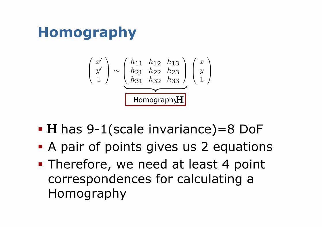
Homography
has 9-1(scale invariance)=8 DoF A pair of points gives us 2 equations Therefore, we need at least 4 point
correspondences for calculating a Homography
Homography
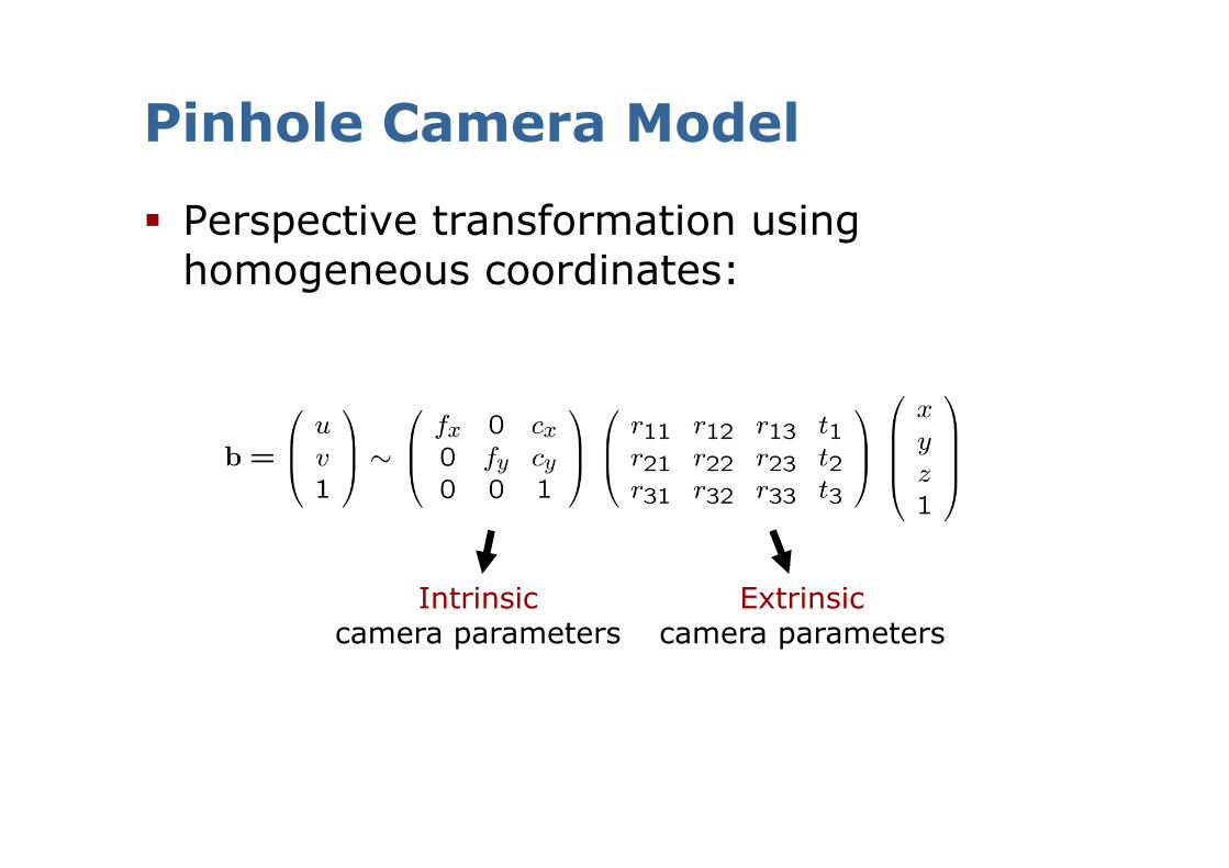
Pinhole Camera Model
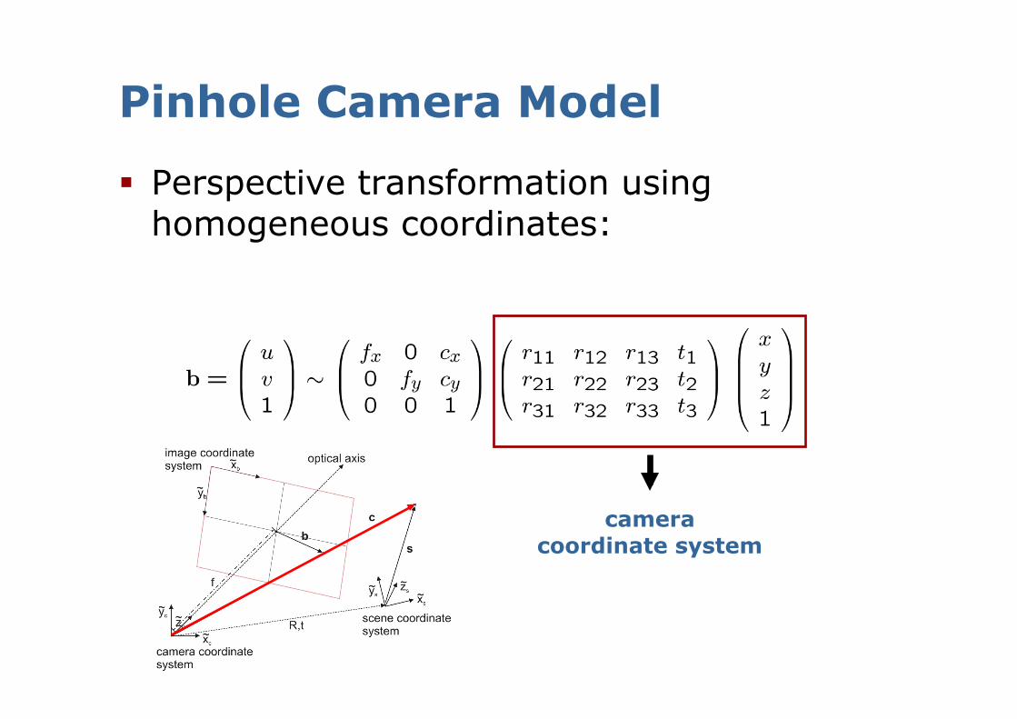
Perspective transformation using homogeneous coordinates:
Intrinsic camera parameters
Extrinsic camera parameters
Pinhole Camera Model
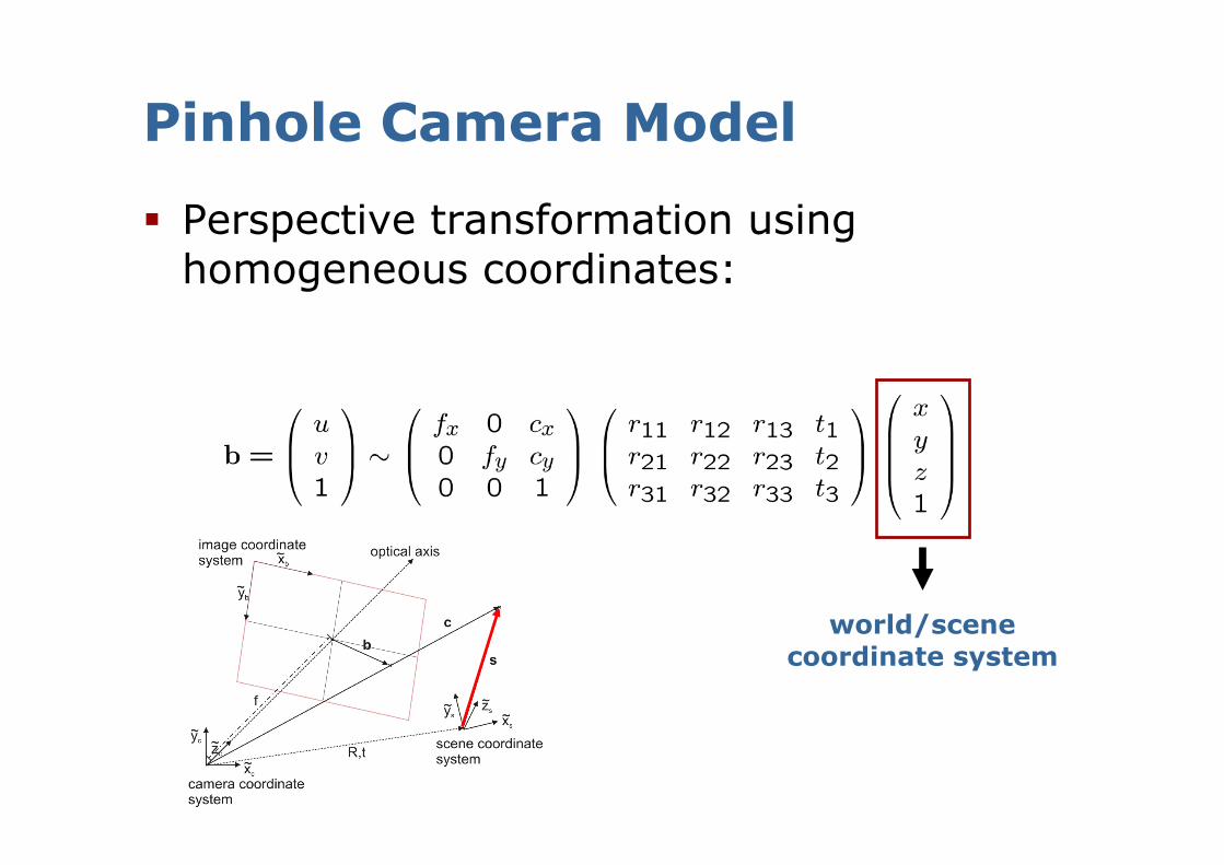
Pinhole Camera Model
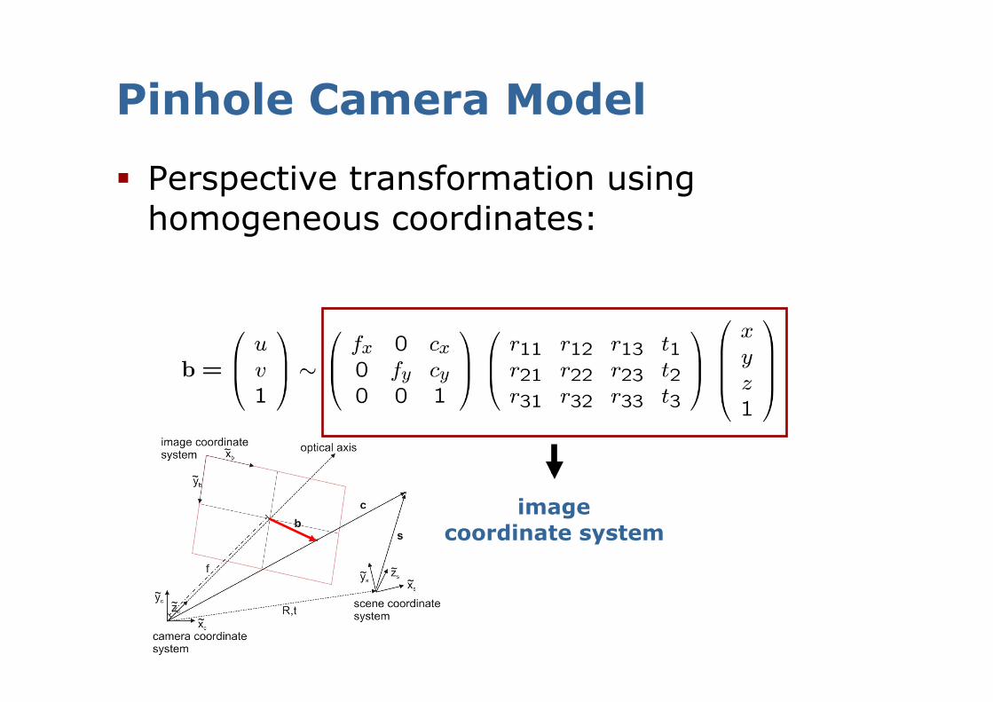
Perspective transformation using homogeneous coordinates:
world/scene coordinate system
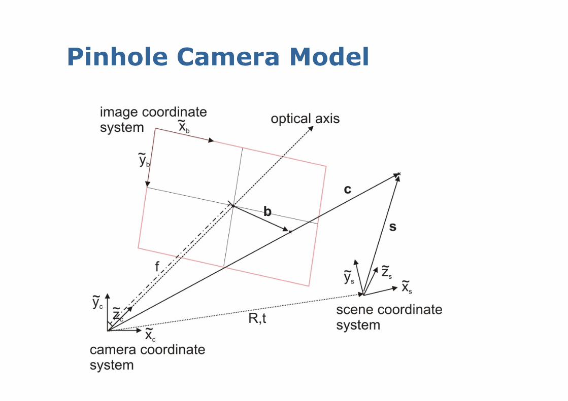
Pinhole Camera Model
Perspective transformation using homogeneous coordinates:
camera coordinate system
Pinhole Camera Model
Perspective transformation using homogeneous coordinates:
image coordinate system
Pinhole Camera Model
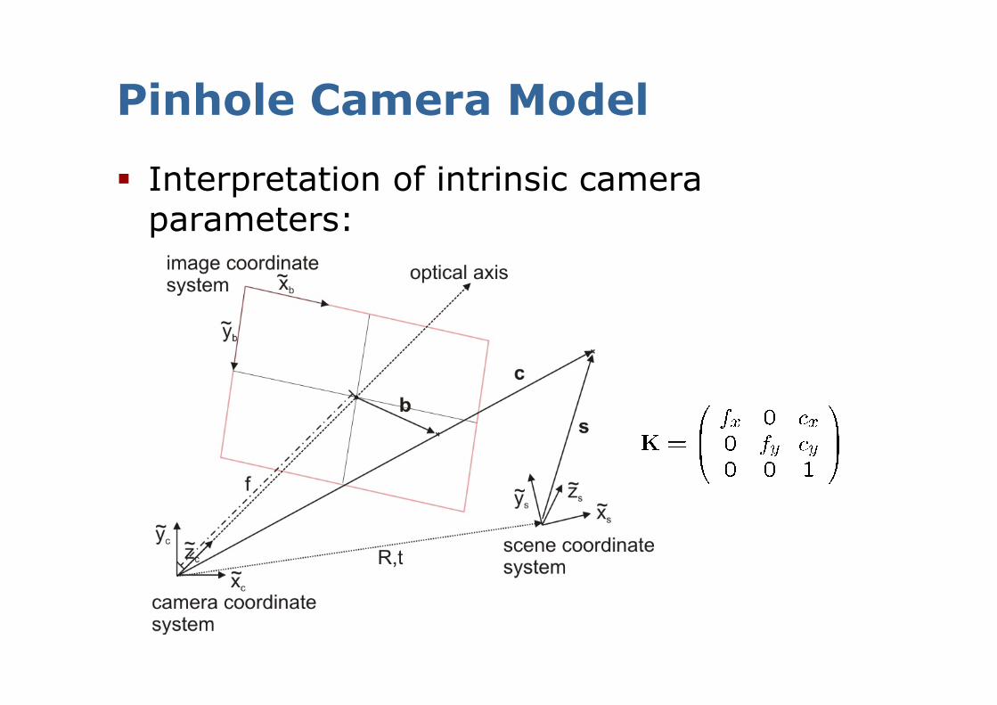
Interpretation of intrinsic camera parameters:
Pinhole Camera Model
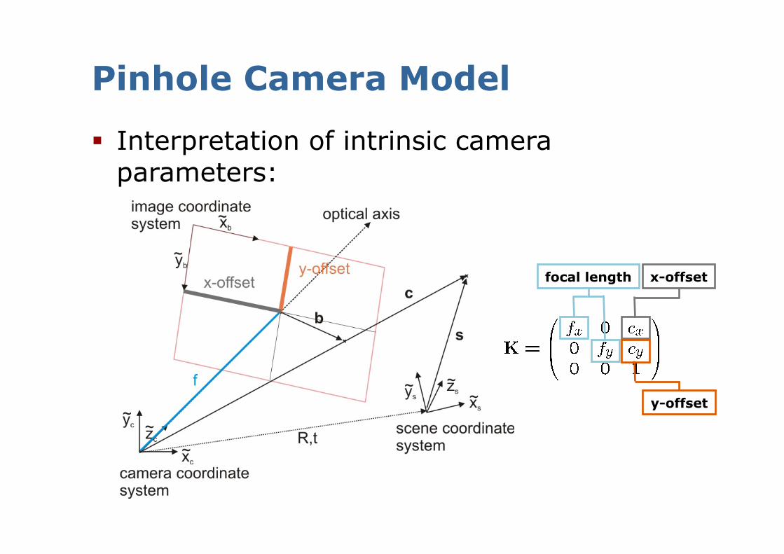
Interpretation of intrinsic camera parameters:
focal length x-offset
y-offset
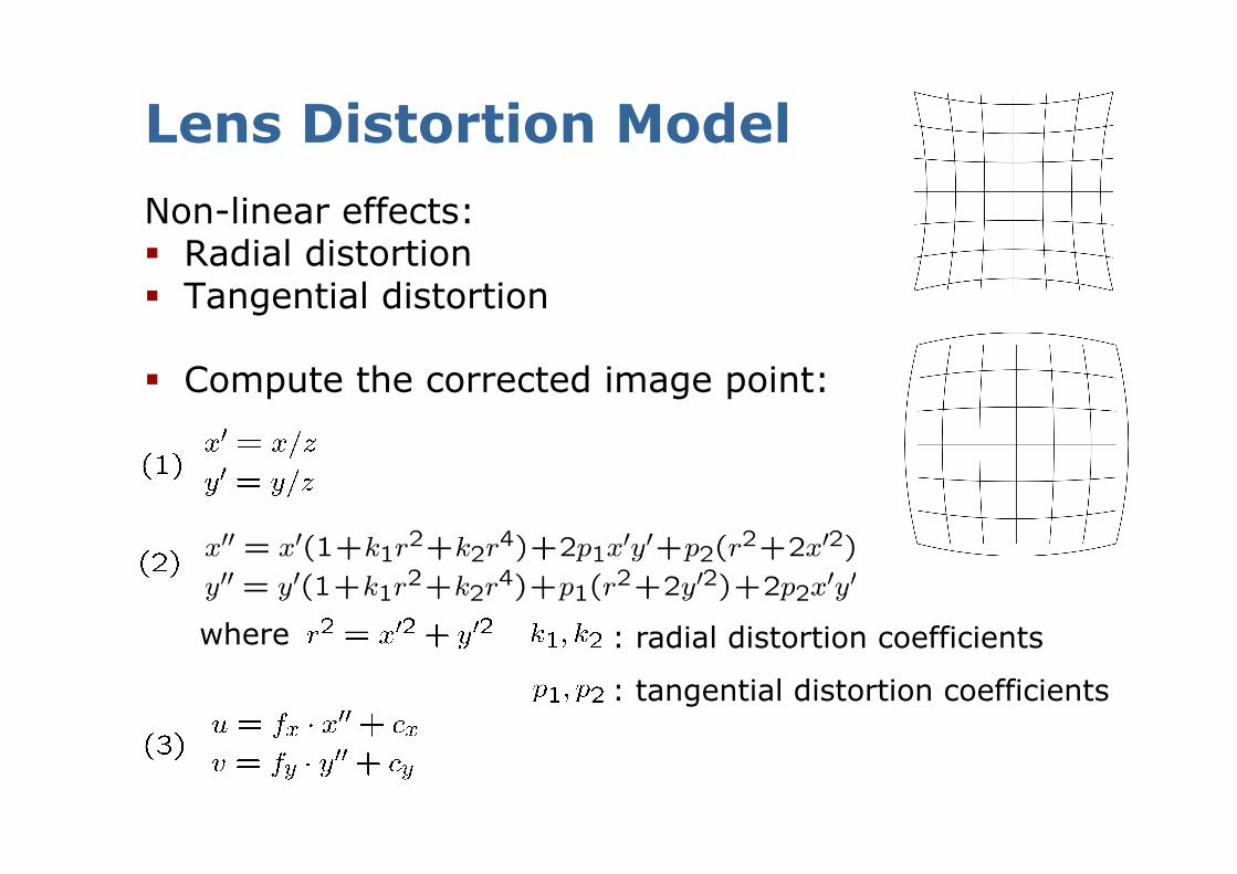
Non-linear effects: Radial distortion Tangential distortion
Compute the corrected image point:
Lens Distortion Model
where : radial distortion coefficients
: tangential distortion coefficients
Camera Calibration
Calculate intrinsic parameters and lens distortion from a series of images 2D camera calibration 3D camera calibration Self calibration
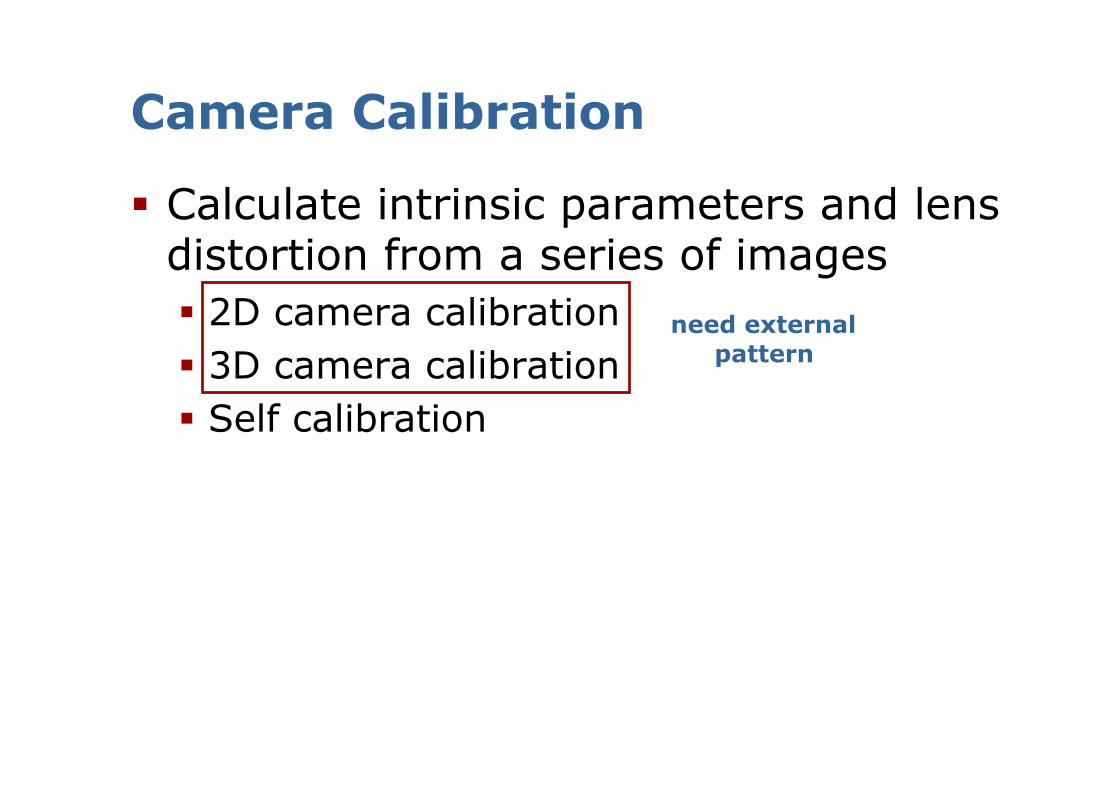
Camera Calibration
Calculate intrinsic parameters and lens distortion from a series of images 2D camera calibration 3D camera calibration Self calibration
need external pattern
Camera Calibration
Calculate intrinsic parameters and lens distortion from a series of images 2D camera calibration 3D camera calibration Self calibration
2D Camera Calibration
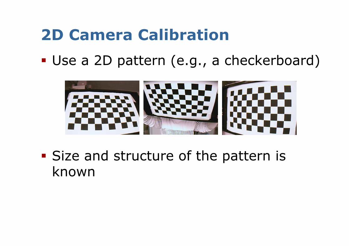
Use a 2D pattern (e.g., a checkerboard)
Size and structure of the pattern is known
Trick for 2D Camera Calibration
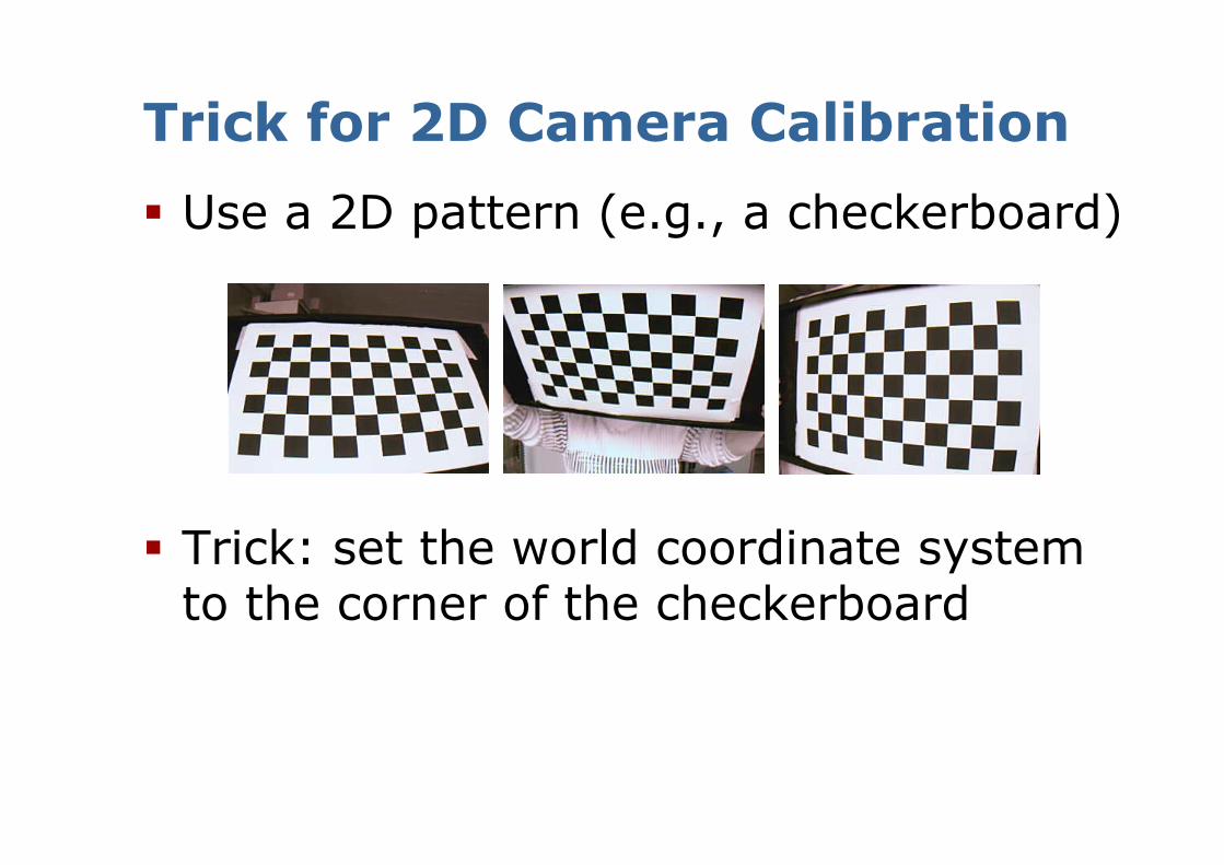
Use a 2D pattern (e.g., a checkerboard)
Trick: set the world coordinate system to the corner of the checkerboard

Trick for 2D Camera Calibration
Use a 2D pattern (e.g., a checkerboard)
Trick: set the world coordinate system to the corner of the checkerboard
Now: All points on the checkerboard lie in one plane!
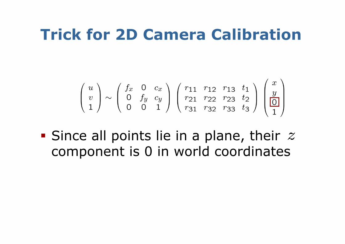
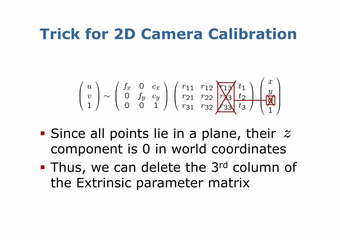
Since all points lie in a plane, their component is 0 in world coordinates
Trick for 2D Camera Calibration
Since all points lie in a plane, their component is 0 in world coordinates
Trick for 2D Camera Calibration
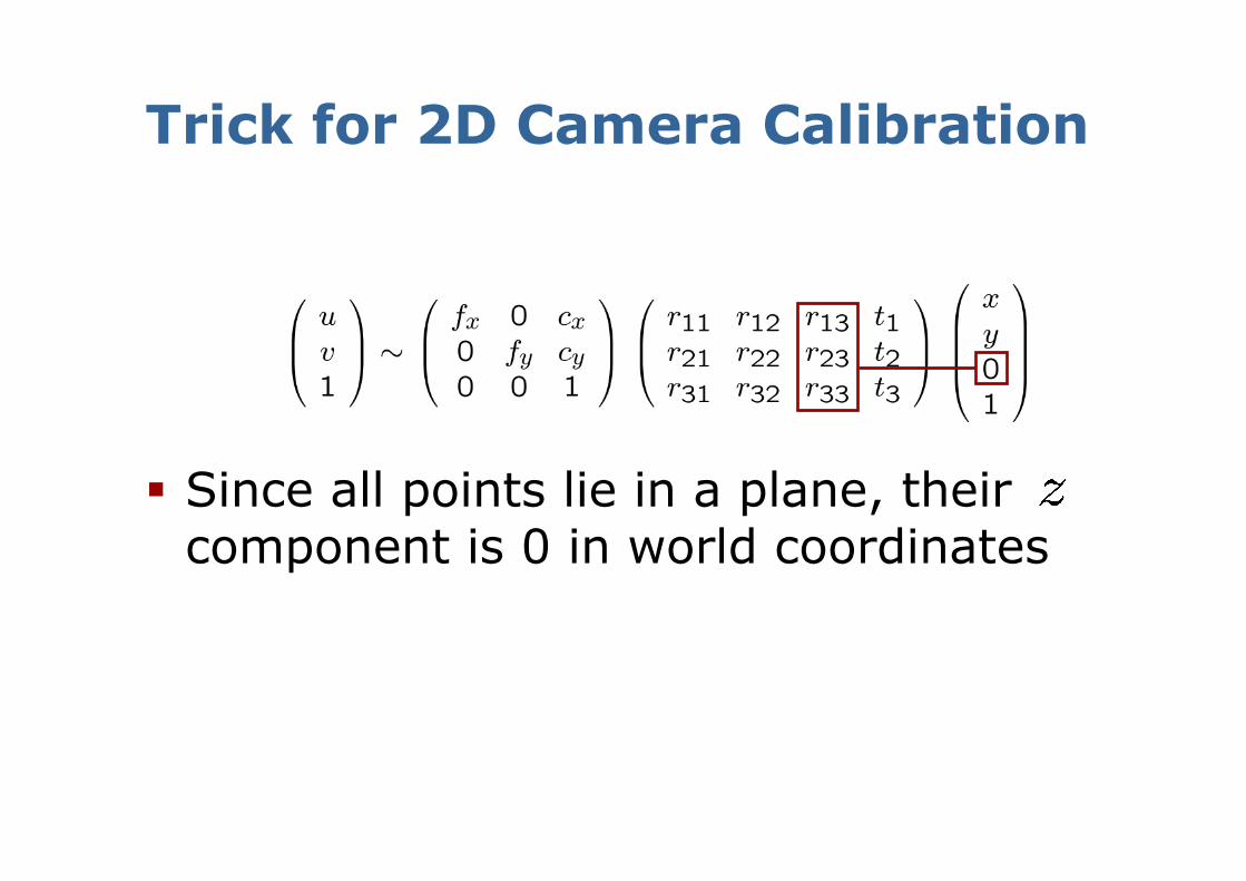
Since all points lie in a plane, their component is 0 in world coordinates
Thus, we can delete the 3rd column of the Extrinsic parameter matrix
Trick for 2D Camera Calibration
Since all points lie in a plane, their component is 0 in world coordinates
Thus, we can delete the 3rd column of the Extrinsic parameter matrix
Simplified Form for 2D Camera Calibration
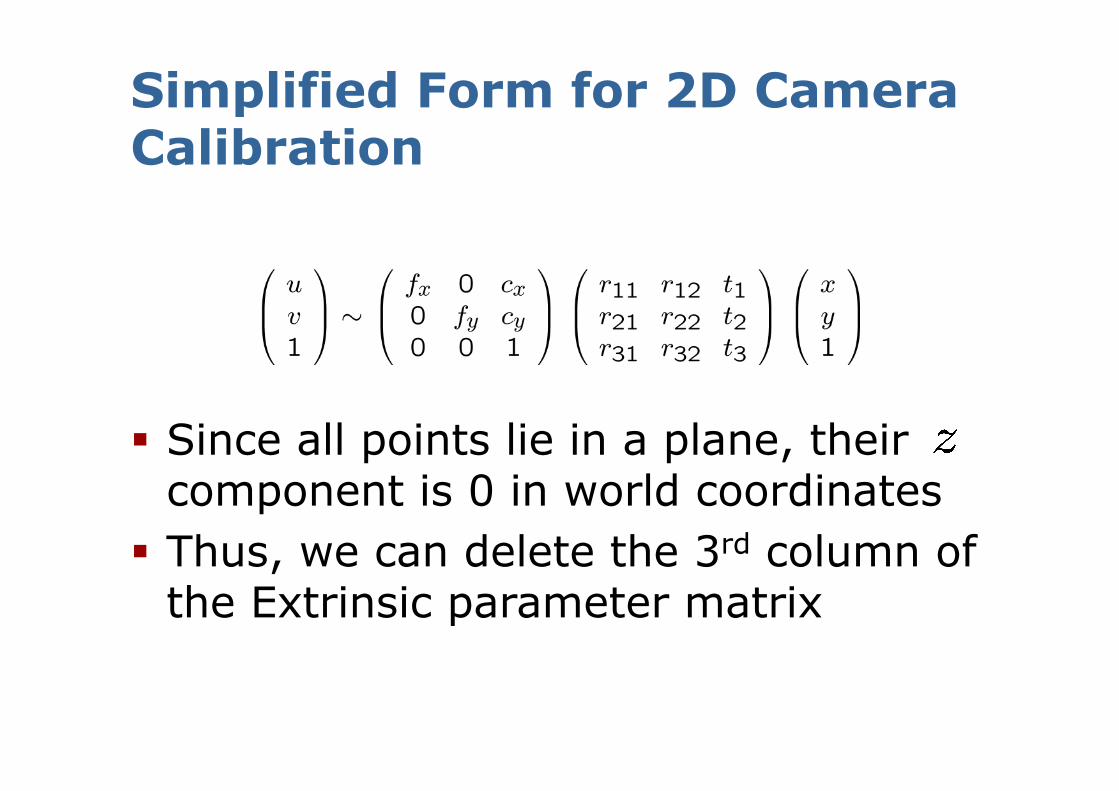
Since all points lie in a plane, their component is 0 in world coordinates
Thus, we can delete the 3rd column of the Extrinsic parameter matrix
Simplified Form for 2D Camera Calibration
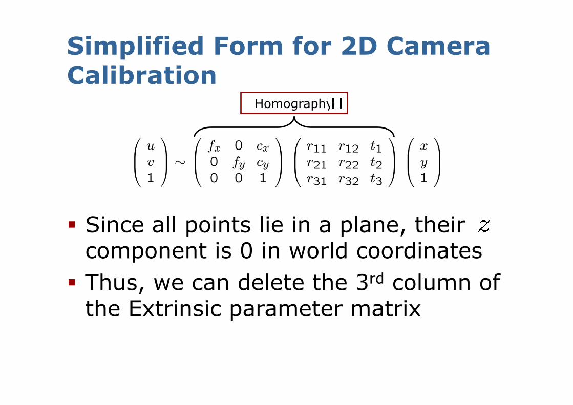
Homography
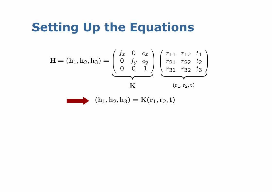
Setting Up the Equations
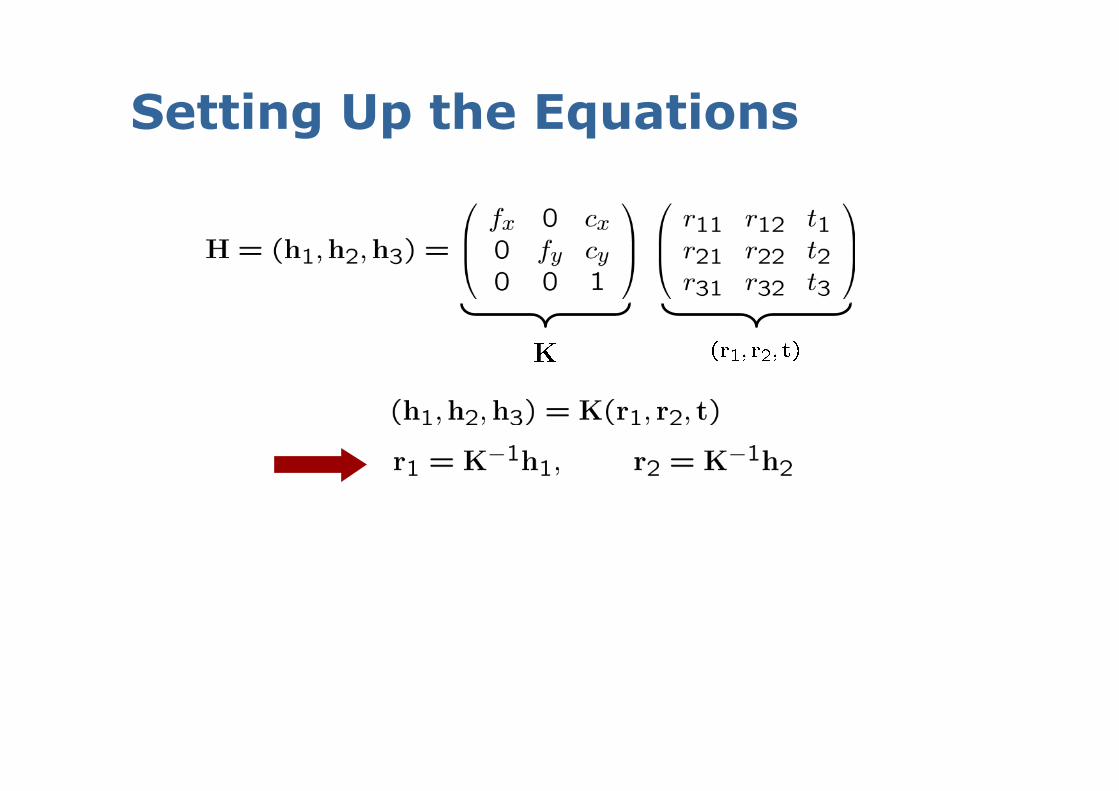
Setting Up the Equations
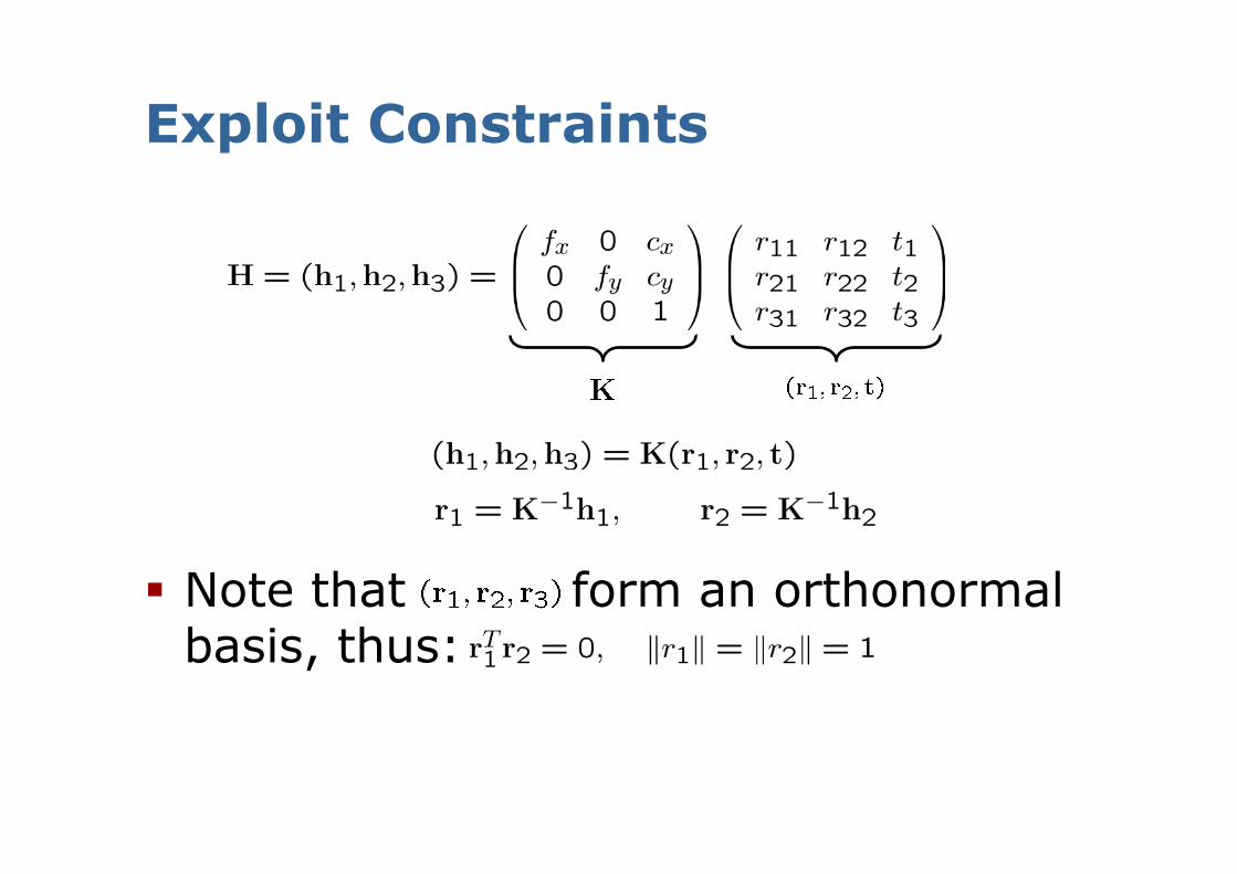
Exploit Constraints
Note that form an orthonormal basis, thus:
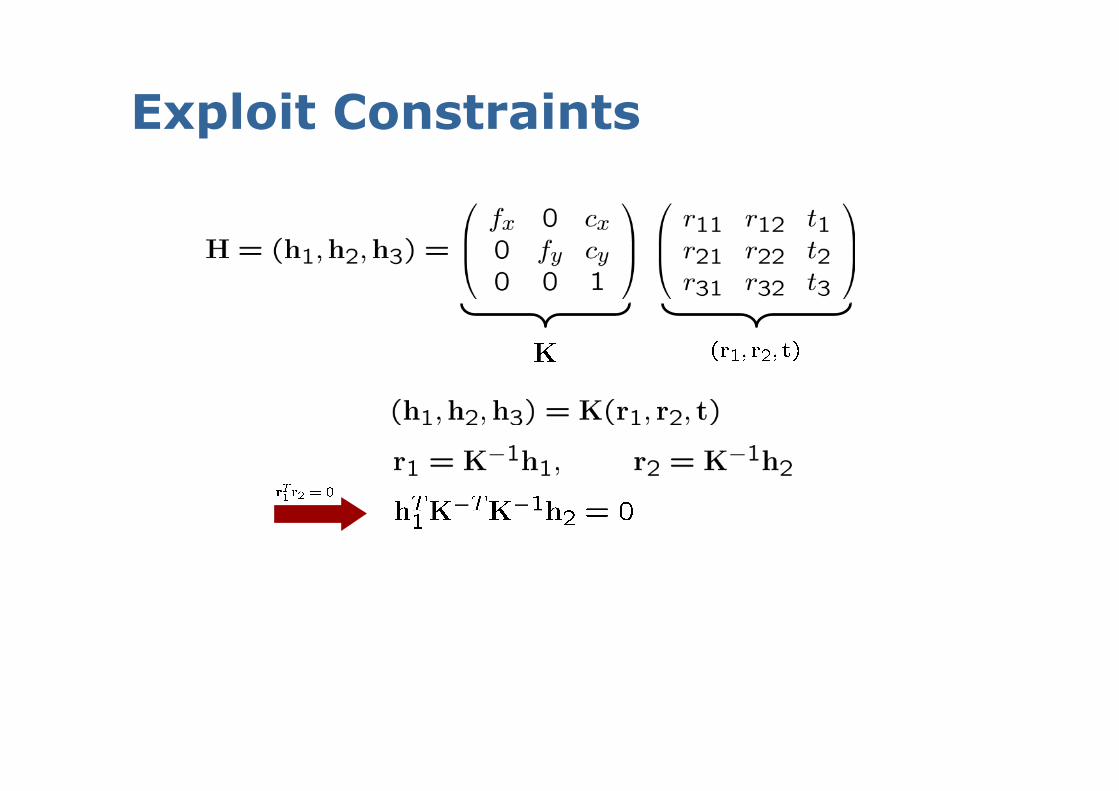
Exploit Constraints
Exploit Constraints
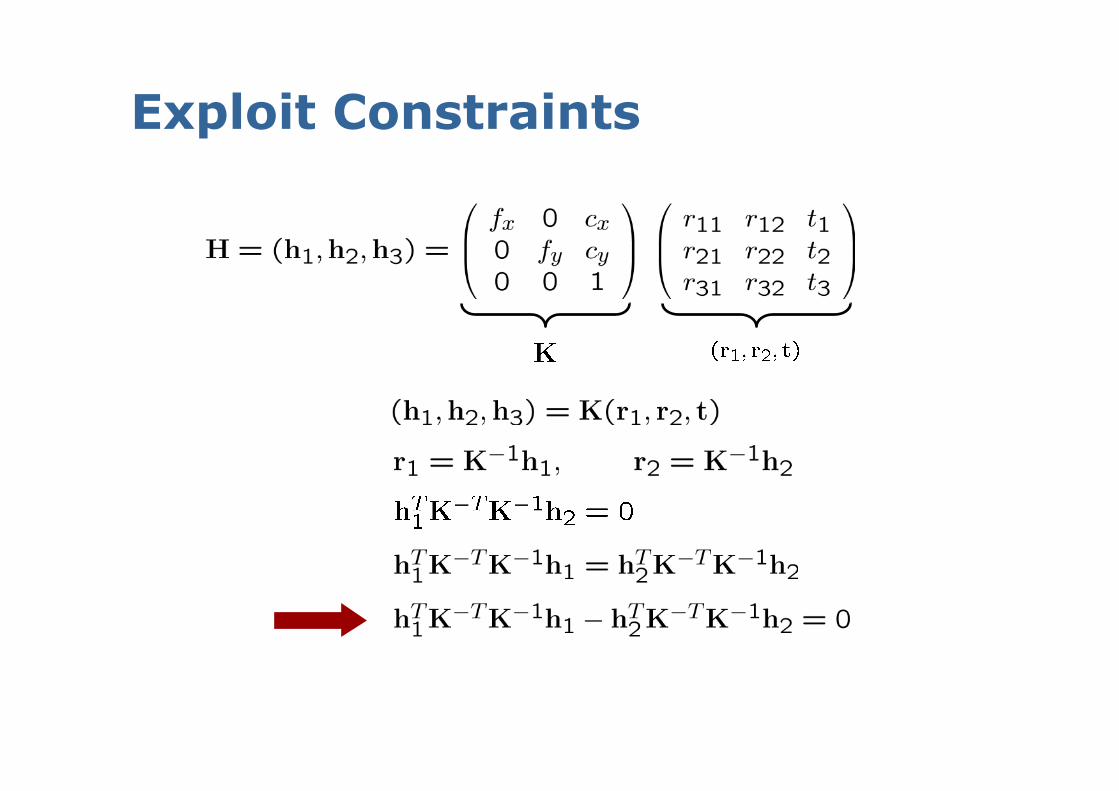
Exploit Constraints
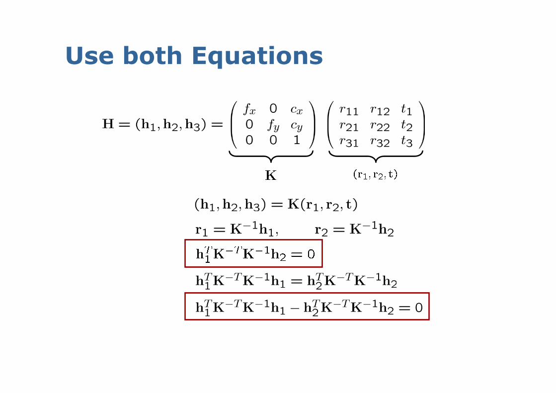
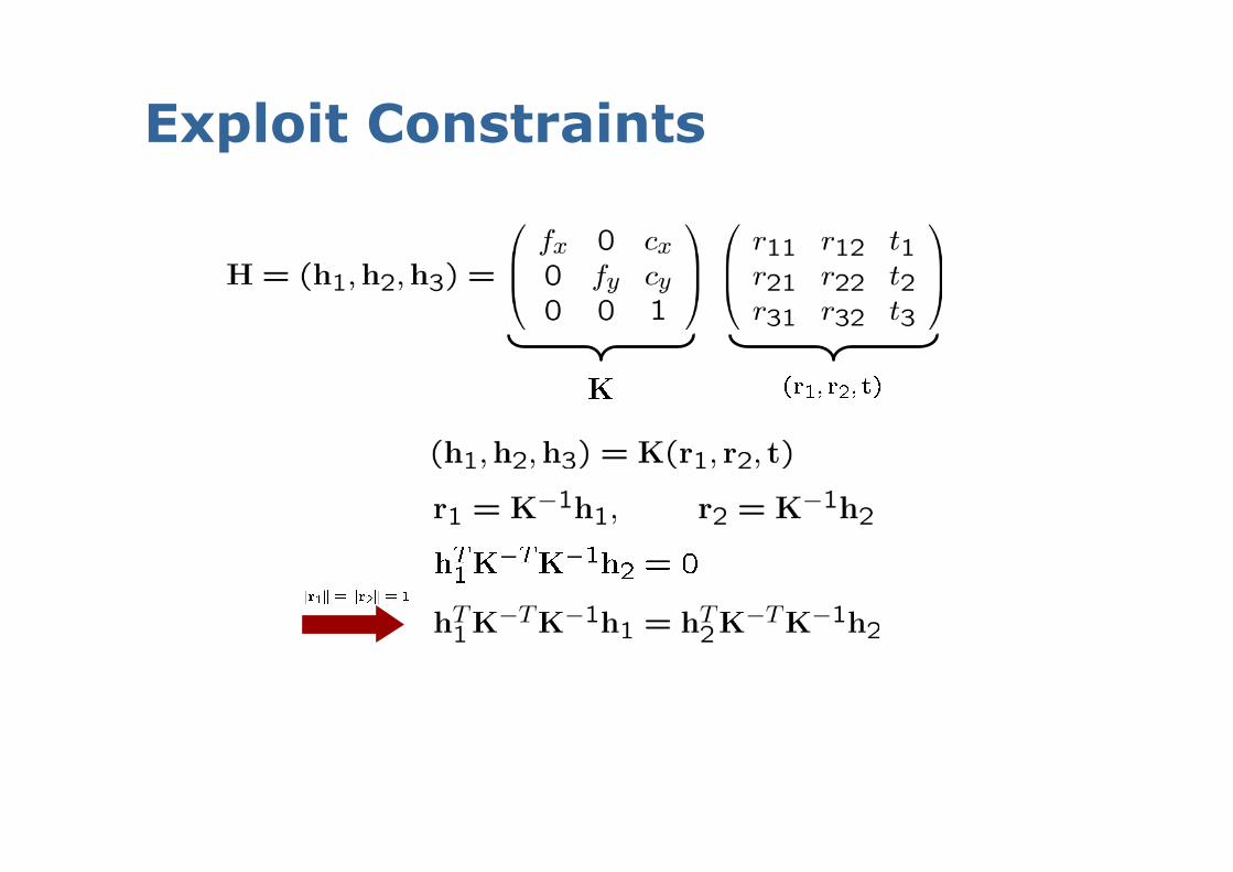
Use both Equations
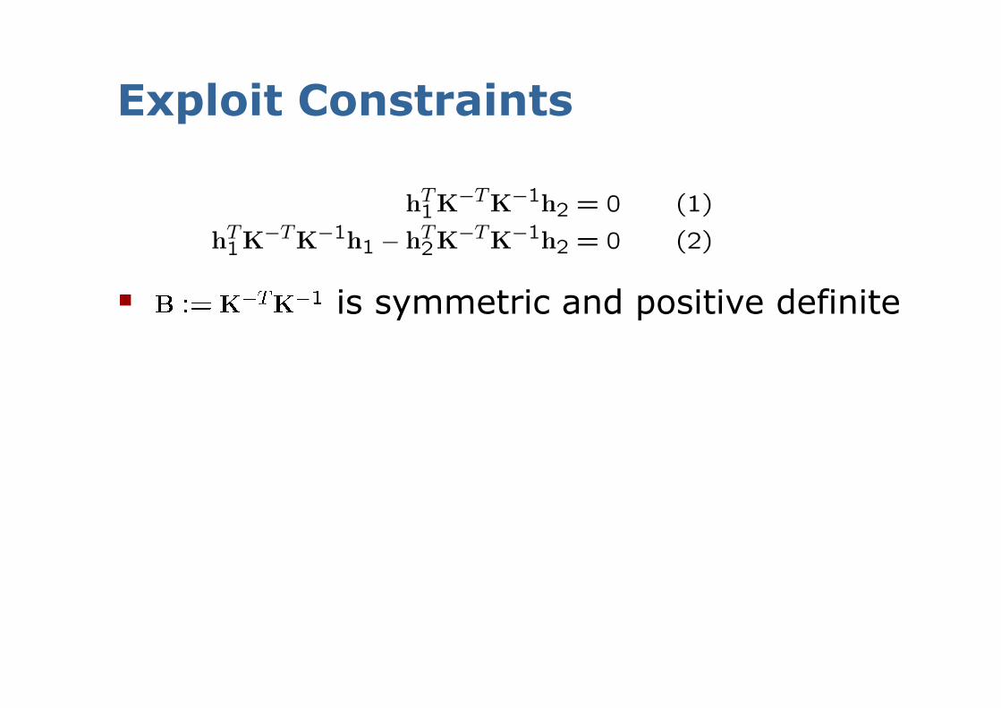
Exploit Constraints
is symmetric and positive definite
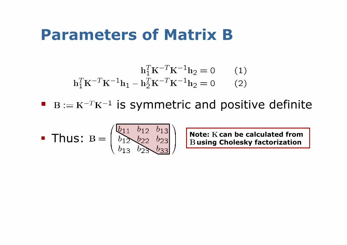
Parameters of Matrix B
is symmetric and positive definite
Thus: Note: K can be calculated from B using Cholesky factorization
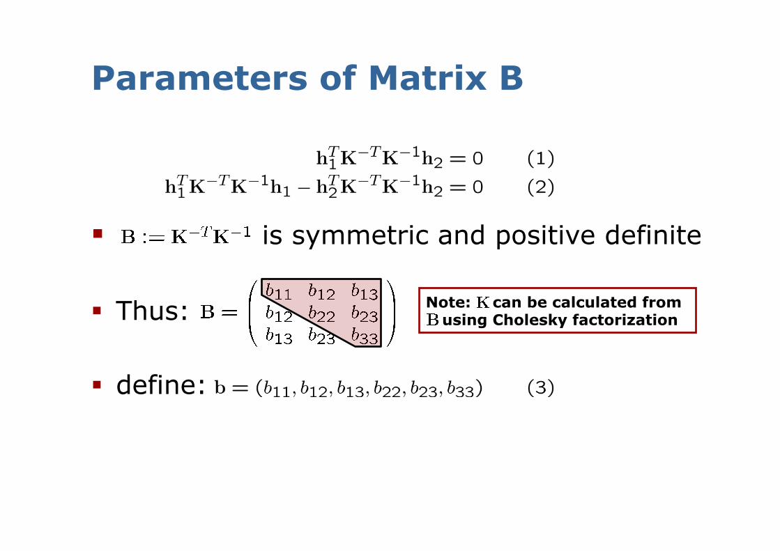
Parameters of Matrix B
is symmetric and positive definite
Thus:
define:
Note: K can be calculated from B using Cholesky factorization
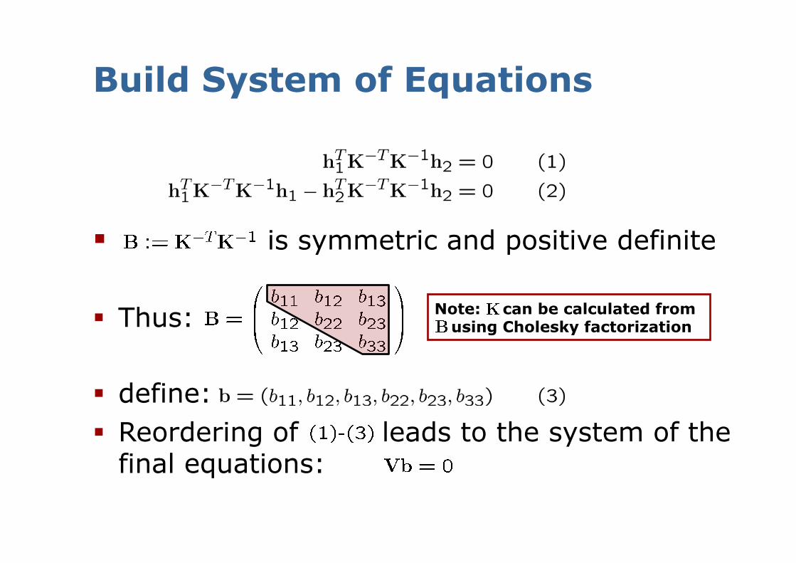
Build System of Equations
is symmetric and positive definite
Thus:
define: Reordering of leads to the system of the
final equations:
Note: K can be calculated from B using Cholesky factorization
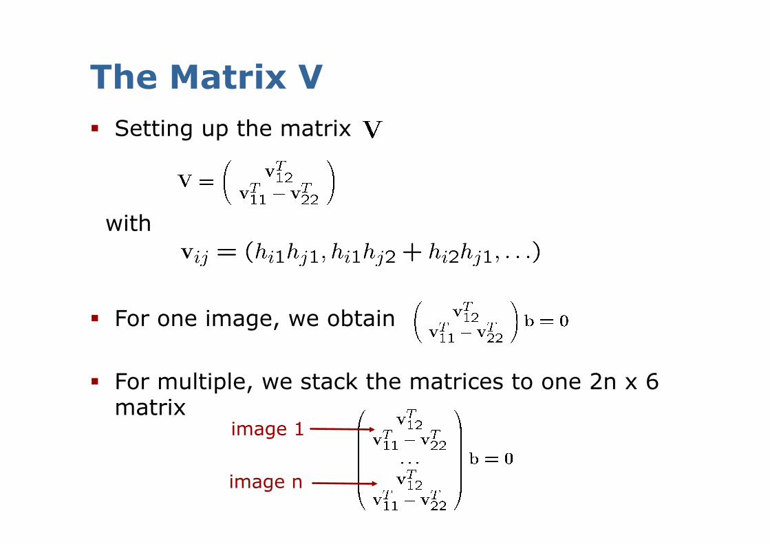
The Matrix V Setting up the matrix
with
For one image, we obtain
For multiple, we stack the matrices to one 2n x 6 matrix
image 1
image n
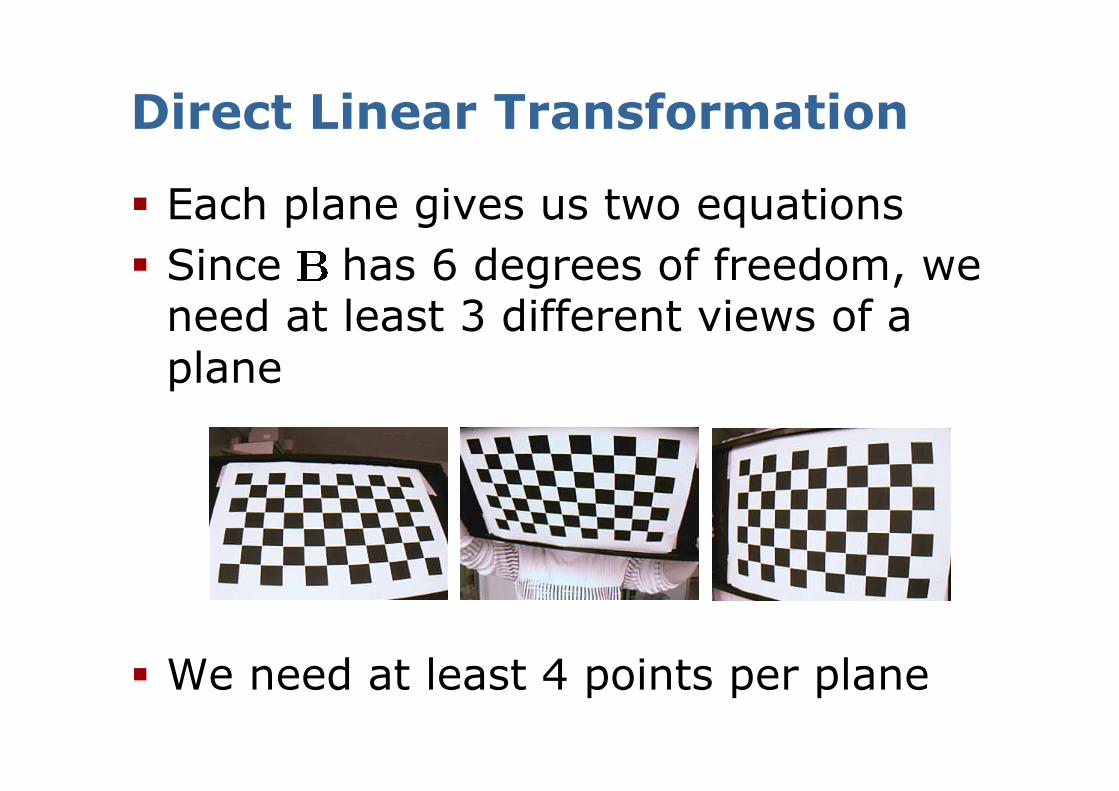
Direct Linear Transformation
Each plane gives us two equations Since has 6 degrees of freedom, we
need at least 3 different views of a plane
We need at least 4 points per plane
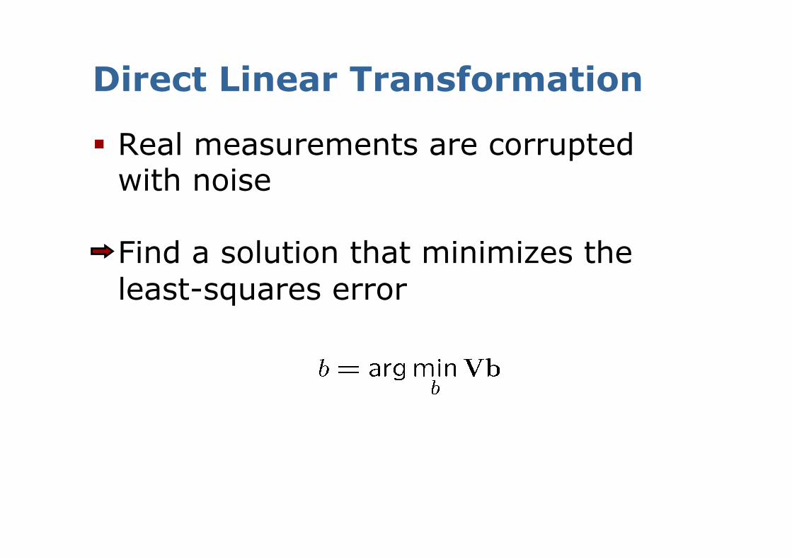
Direct Linear Transformation
Real measurements are corrupted with noise
Find a solution that minimizes the least-squares error
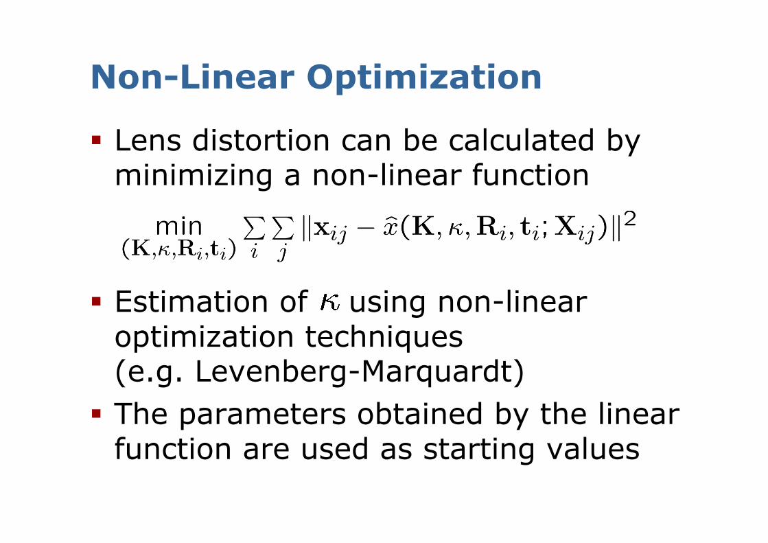
Non-Linear Optimization
Lens distortion can be calculated by minimizing a non-linear function
Estimation of using non-linear optimization techniques (e.g. Levenberg-Marquardt)
The parameters obtained by the linear function are used as starting values
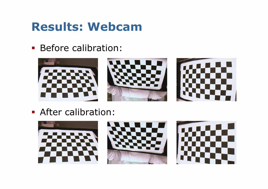
Results: Webcam
Before calibration:
After calibration:
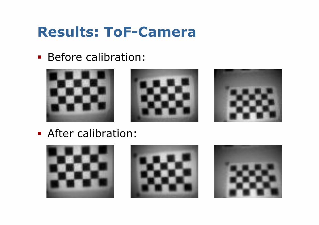
Results: ToF-Camera
Before calibration:
After calibration:
Summary
Pinhole Camera Model Non-linear model for lens distortion Approach to 2D Calibration that
accurately determines the model parameters and
is easy to realize


![Particle FiltersExample 3: Example Particle Distributions [Grisetti, Stachniss, Burgard, T-RO2006] Particles generated from the approximately optimal proposal distribution. If using](https://static.documents.pub/doc/80x56/6009df1300824e6d72397cde/particle-filters-example-3-example-particle-distributions-grisetti-stachniss.jpg)


