35
Robotics – Sensors & ActuatorsMatteo Matteucci – [email protected]
Matteo Matteucci – [email protected]
2What does it make a mobile robot?
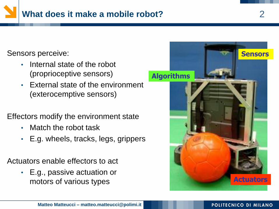
Sensors perceive:
• Internal state of the robot
(proprioceptive sensors)
• External state of the environment
(exterocemptive sensors)
Effectors modify the environment state
• Match the robot task
• E.g. wheels, tracks, legs, grippers
Actuators enable effectors to act
• E.g., passive actuation or
motors of various types
Plan
Sense
ActActuators
Sensors
Algorithms
Matteo Matteucci – [email protected]
3Type of Actuators
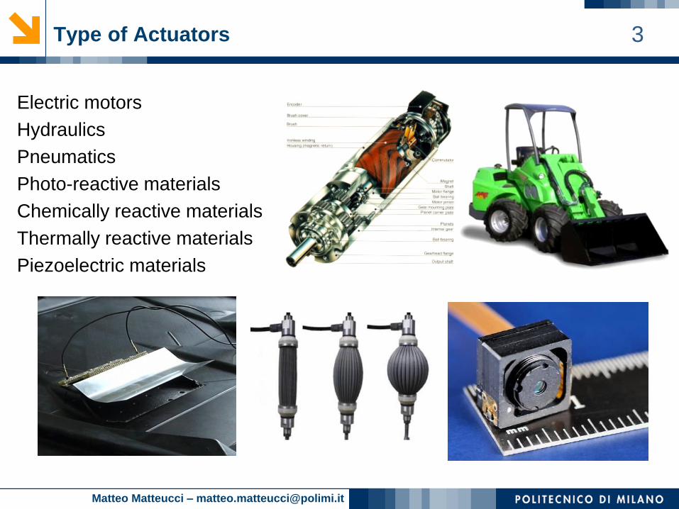
Electric motors
Hydraulics
Pneumatics
Photo-reactive materials
Chemically reactive materials
Thermally reactive materials
Piezoelectric materials
Matteo Matteucci – [email protected]
4Most Popular Actuators
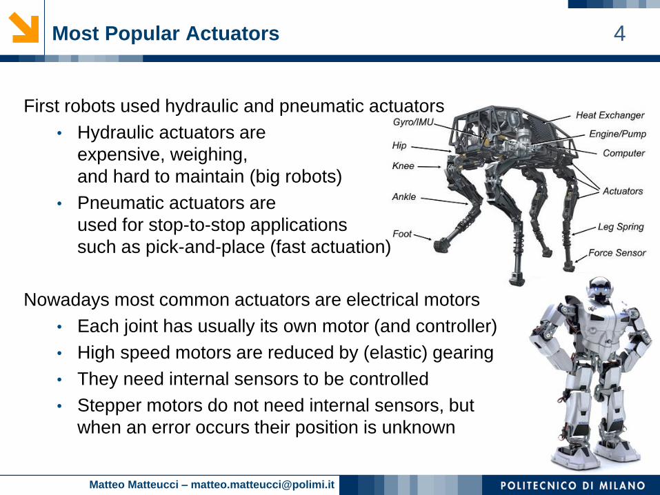
First robots used hydraulic and pneumatic actuators
• Hydraulic actuators are
expensive, weighing,
and hard to maintain (big robots)
• Pneumatic actuators are
used for stop-to-stop applications
such as pick-and-place (fast actuation)
Nowadays most common actuators are electrical motors
• Each joint has usually its own motor (and controller)
• High speed motors are reduced by (elastic) gearing
• They need internal sensors to be controlled
• Stepper motors do not need internal sensors, but
when an error occurs their position is unknown
Matteo Matteucci – [email protected]
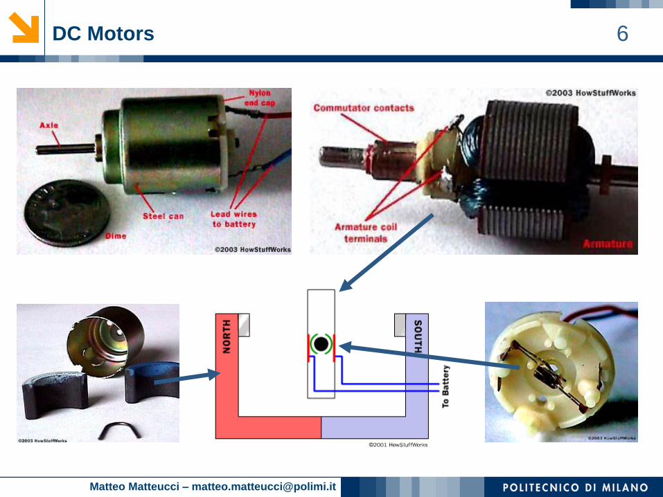
5DC Motors
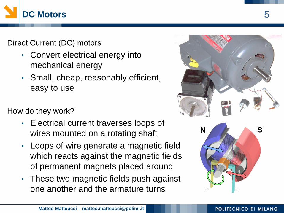
Direct Current (DC) motors
• Convert electrical energy into
mechanical energy
• Small, cheap, reasonably efficient,
easy to use
How do they work?
• Electrical current traverses loops of
wires mounted on a rotating shaft
• Loops of wire generate a magnetic field
which reacts against the magnetic fields
of permanent magnets placed around
• These two magnetic fields push against
one another and the armature turns
Matteo Matteucci – [email protected]
7DC Motors: Brushed and Brushless Motors
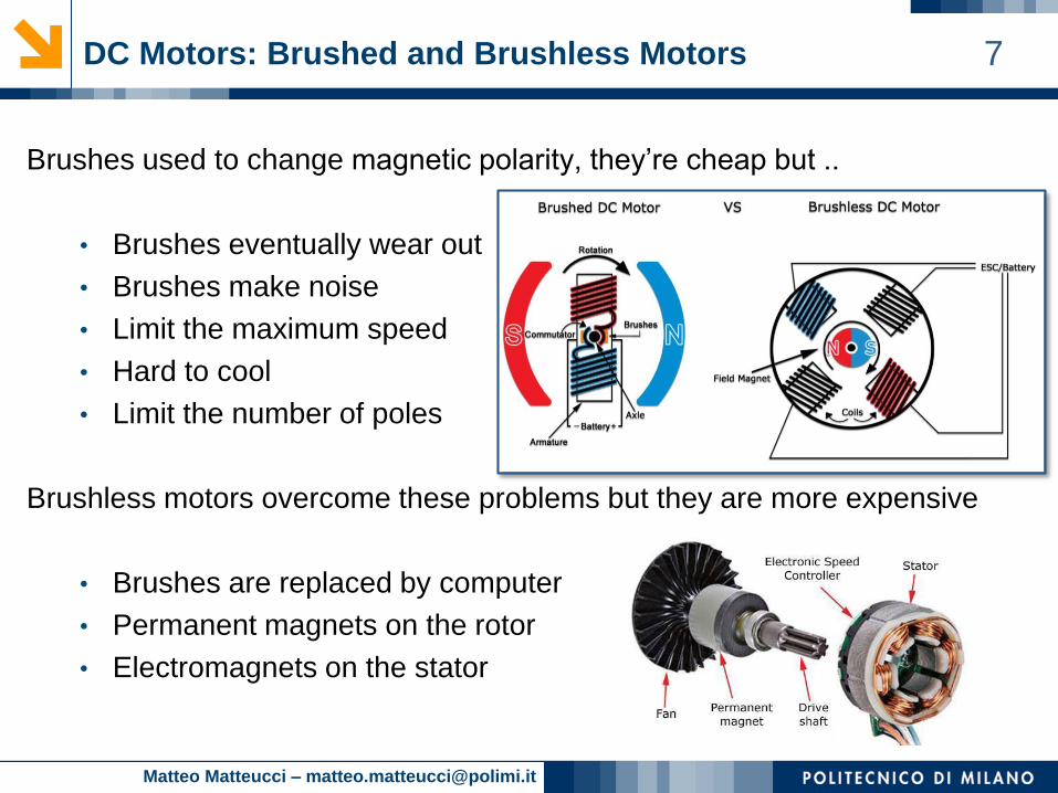
Brushes used to change magnetic polarity, they’re cheap but ..
• Brushes eventually wear out
• Brushes make noise
• Limit the maximum speed
• Hard to cool
• Limit the number of poles
Brushless motors overcome these problems but they are more expensive
• Brushes are replaced by computer
• Permanent magnets on the rotor
• Electromagnets on the stator
Matteo Matteucci – [email protected]
8Torque in a DC motor
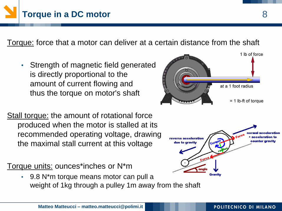
Torque: force that a motor can deliver at a certain distance from the shaft
• Strength of magnetic field generated
is directly proportional to the
amount of current flowing and
thus the torque on motor's shaft
Stall torque: the amount of rotational force
produced when the motor is stalled at its
recommended operating voltage, drawing
the maximal stall current at this voltage
Torque units: ounces*inches or N*m
• 9.8 N*m torque means motor can pull a
weight of 1kg through a pulley 1m away from the shaft
Matteo Matteucci – [email protected]
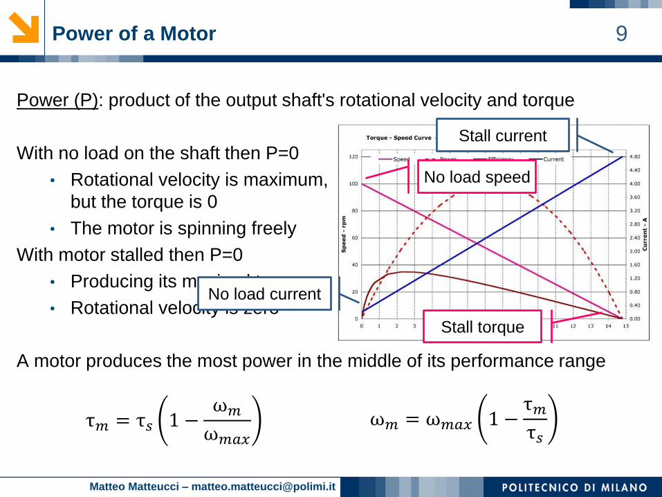
9Power of a Motor
Power (P): product of the output shaft's rotational velocity and torque
With no load on the shaft then P=0
• Rotational velocity is maximum,
but the torque is 0
• The motor is spinning freely
With motor stalled then P=0
• Producing its maximal torque
• Rotational velocity is zero
A motor produces the most power in the middle of its performance range
τ𝑚 = τ𝑠 1 −ω𝑚
ω𝑚𝑎𝑥
ω𝑚 = ω𝑚𝑎𝑥 1 −τ𝑚τ𝑠
No load speed
No load current
Stall torque
Stall current
Matteo Matteucci – [email protected]
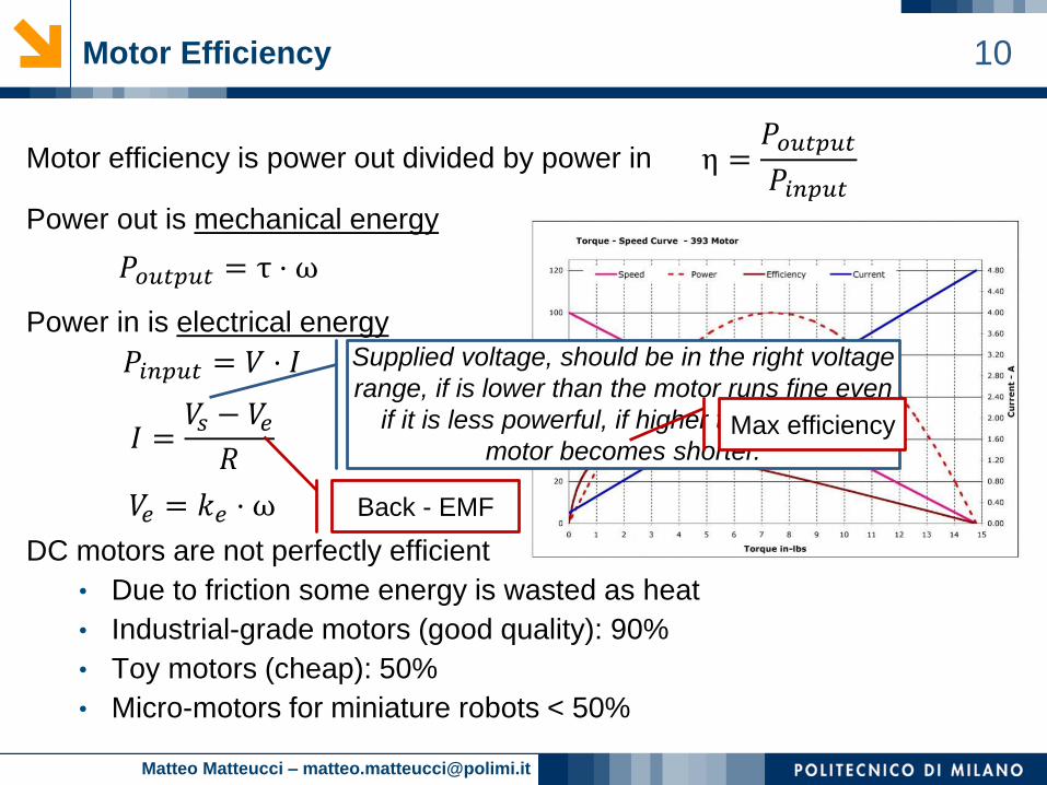
10Motor Efficiency
Motor efficiency is power out divided by power in
Power out is mechanical energy
Power in is electrical energy
DC motors are not perfectly efficient
• Due to friction some energy is wasted as heat
• Industrial-grade motors (good quality): 90%
• Toy motors (cheap): 50%
• Micro-motors for miniature robots < 50%
𝑃𝑜𝑢𝑡𝑝𝑢𝑡 = τ ⋅ ω
𝑃𝑖𝑛𝑝𝑢𝑡 = 𝑉 ⋅ 𝐼
𝐼 =𝑉𝑠 − 𝑉𝑒𝑅
𝑉𝑒 = 𝑘𝑒 ⋅ ω
η =𝑃𝑜𝑢𝑡𝑝𝑢𝑡
𝑃𝑖𝑛𝑝𝑢𝑡
Supplied voltage, should be in the right voltage
range, if is lower than the motor runs fine even
if it is less powerful, if higher the life of the
motor becomes shorter.Max efficiency
Back - EMF
Matteo Matteucci – [email protected]
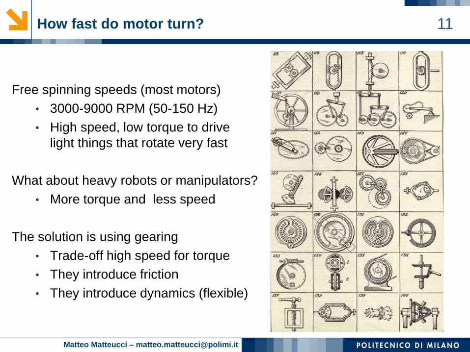
11How fast do motor turn?
Free spinning speeds (most motors)
• 3000-9000 RPM (50-150 Hz)
• High speed, low torque to drive
light things that rotate very fast
What about heavy robots or manipulators?
• More torque and less speed
The solution is using gearing
• Trade-off high speed for torque
• They introduce friction
• They introduce dynamics (flexible)
Matteo Matteucci – [email protected]
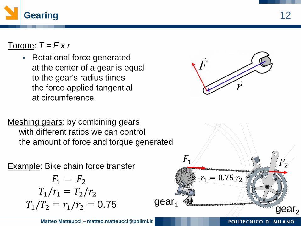
12Gearing
Torque: T = F x r
• Rotational force generated
at the center of a gear is equal
to the gear's radius times
the force applied tangential
at circumference
Meshing gears: by combining gears
with different ratios we can control
the amount of force and torque generated
Example: Bike chain force transfer
𝐹1 = 𝐹2𝑇1/𝑟1 = 𝑇2/𝑟2
𝑇1/𝑇2 = 𝑟1/𝑟2 = 0.75
𝑟1 = 0.75 𝑟2
gear1gear2
𝐹1 𝐹2
Matteo Matteucci – [email protected]
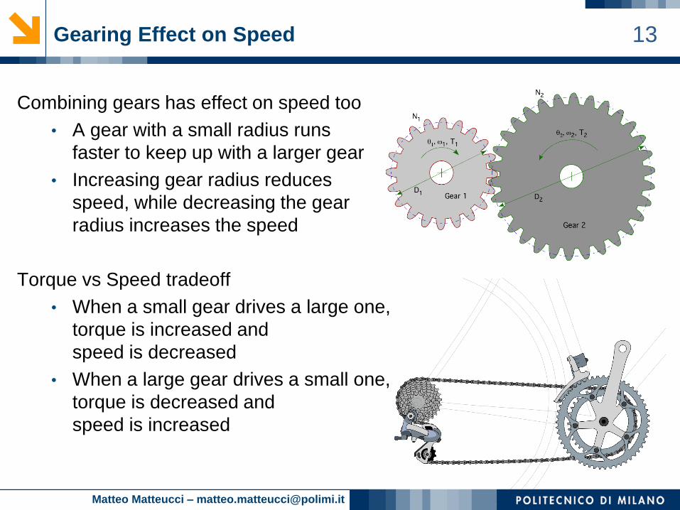
13Gearing Effect on Speed
Combining gears has effect on speed too
• A gear with a small radius runs
faster to keep up with a larger gear
• Increasing gear radius reduces
speed, while decreasing the gear
radius increases the speed
Torque vs Speed tradeoff
• When a small gear drives a large one,
torque is increased and
speed is decreased
• When a large gear drives a small one,
torque is decreased and
speed is increased
Matteo Matteucci – [email protected]
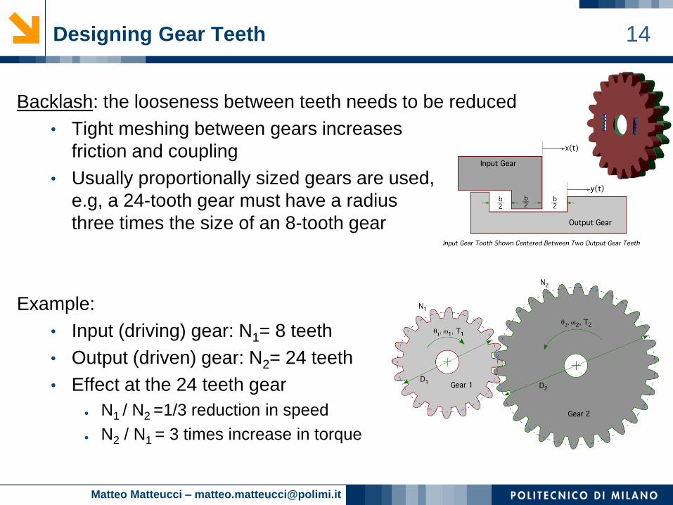
14Designing Gear Teeth
Backlash: the looseness between teeth needs to be reduced
• Tight meshing between gears increases
friction and coupling
• Usually proportionally sized gears are used,
e.g, a 24-tooth gear must have a radius
three times the size of an 8-tooth gear
Example:
• Input (driving) gear: N1= 8 teeth
• Output (driven) gear: N2= 24 teeth
• Effect at the 24 teeth gear
● N1 / N2 =1/3 reduction in speed
● N2 / N1 = 3 times increase in torque
Matteo Matteucci – [email protected]
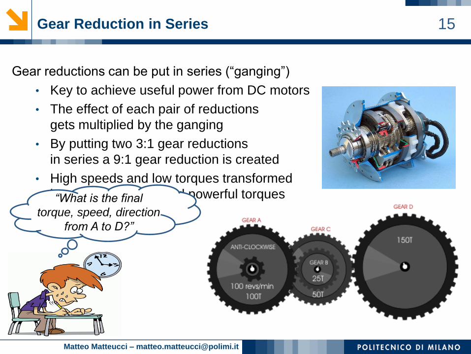
15Gear Reduction in Series
Gear reductions can be put in series (“ganging”)
• Key to achieve useful power from DC motors
• The effect of each pair of reductions
gets multiplied by the ganging
• By putting two 3:1 gear reductions
in series a 9:1 gear reduction is created
• High speeds and low torques transformed
into usable speeds and powerful torques“What is the final
torque, speed, direction
from A to D?”
Matteo Matteucci – [email protected]
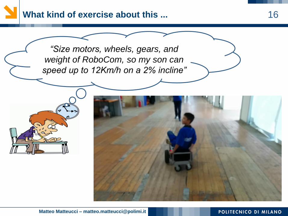
16What kind of exercise about this ...
“Size motors, wheels, gears, and
weight of RoboCom, so my son can
speed up to 12Km/h on a 2% incline”

Matteo Matteucci – [email protected]
17Stepper motors
A stepper motor is a brushless, synchronous electric motor
that converts digital pulses into mechanical shaft rotations.
• Rotation angle proportional to input pulse
• Full torque at standstill (energized windings)
• Precise positioning and repeatability
• Response to starting/stopping/reversing
• Very reliable (no contact brushes)
• Allow open-loop control (simpler and cheaper)
• Allow very low speed synchronous rotation
with a load directly coupled to the shaft.
• Wide range of rotational speeds
• Require a dedicated control circuit
• Use more current than D.C. motors
• Torque reduces at higher speeds
• Resonances can occur if not properly controlled.
• Not easy to operate at extremely high speeds
Matteo Matteucci – [email protected]
18
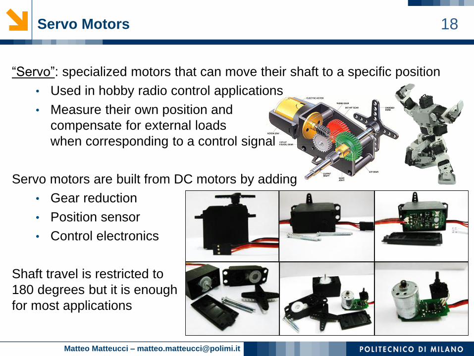
“Servo”: specialized motors that can move their shaft to a specific position
• Used in hobby radio control applications
• Measure their own position and
compensate for external loads
when corresponding to a control signal
Servo motors are built from DC motors by adding
• Gear reduction
• Position sensor
• Control electronics
Shaft travel is restricted to
180 degrees but it is enough
for most applications
Servo Motors
Matteo Matteucci – [email protected]
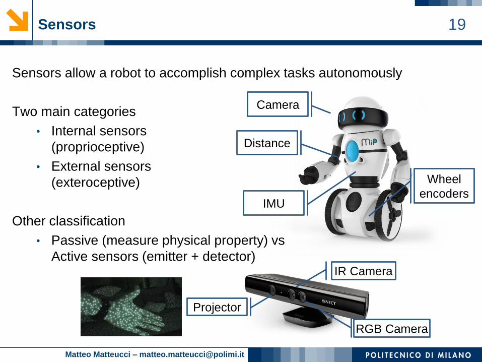
19Sensors
Sensors allow a robot to accomplish complex tasks autonomously
Two main categories
• Internal sensors
(proprioceptive)
• External sensors
(exteroceptive)
Other classification
• Passive (measure physical property) vs
Active sensors (emitter + detector)
Camera
Distance
IMU
Wheel
encoders
Projector
IR Camera
RGB Camera
Matteo Matteucci – [email protected]
20Encoders
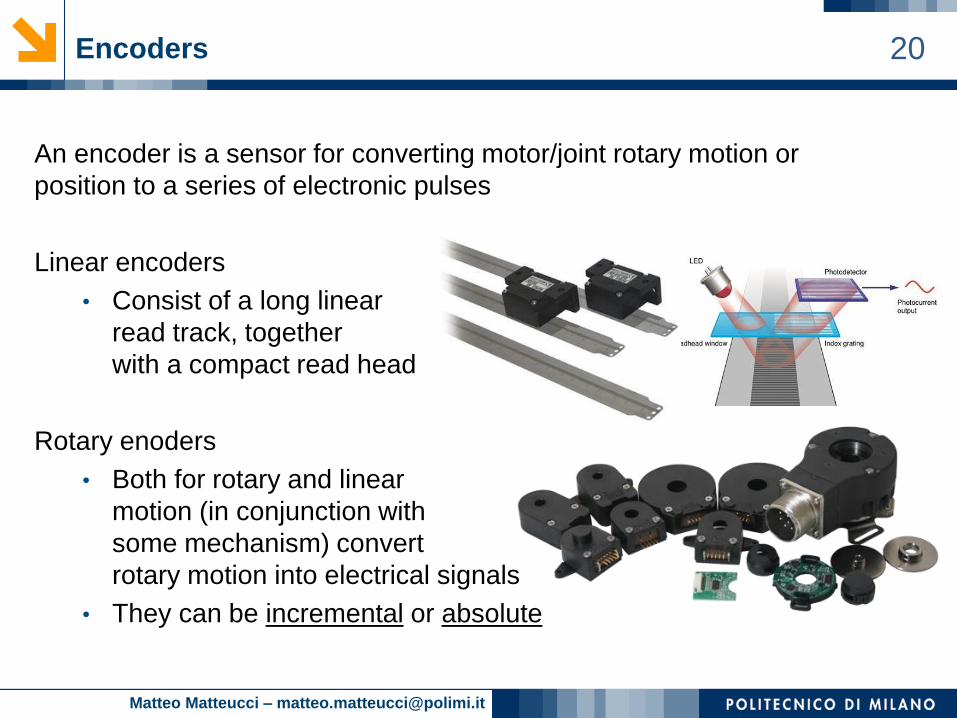
An encoder is a sensor for converting motor/joint rotary motion or
position to a series of electronic pulses
Linear encoders
• Consist of a long linear
read track, together
with a compact read head
Rotary enoders
• Both for rotary and linear
motion (in conjunction with
some mechanism) convert
rotary motion into electrical signals
• They can be incremental or absolute
Matteo Matteucci – [email protected]
21Incremental rotary encoders
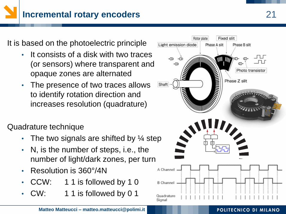
It is based on the photoelectric principle
• It consists of a disk with two traces
(or sensors) where transparent and
opaque zones are alternated
• The presence of two traces allows
to identify rotation direction and
increases resolution (quadrature)
Quadrature technique
• The two signals are shifted by ¼ step
• N, is the number of steps, i.e., the
number of light/dark zones, per turn
• Resolution is 360°/4N
• CCW: 1 1 is followed by 1 0
• CW: 1 1 is followed by 0 1
Matteo Matteucci – [email protected]
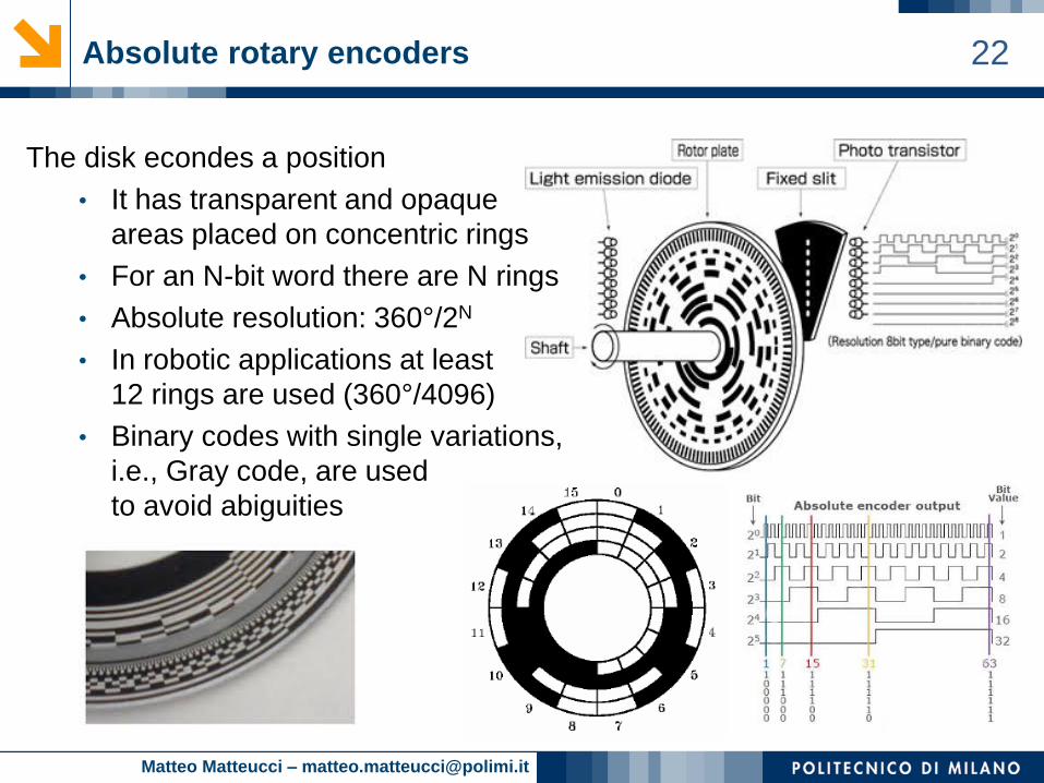
22Absolute rotary encoders
The disk econdes a position
• It has transparent and opaque
areas placed on concentric rings
• For an N-bit word there are N rings
• Absolute resolution: 360°/2N
• In robotic applications at least
12 rings are used (360°/4096)
• Binary codes with single variations,
i.e., Gray code, are used
to avoid abiguities
Matteo Matteucci – [email protected]
23What is measured by sensors?
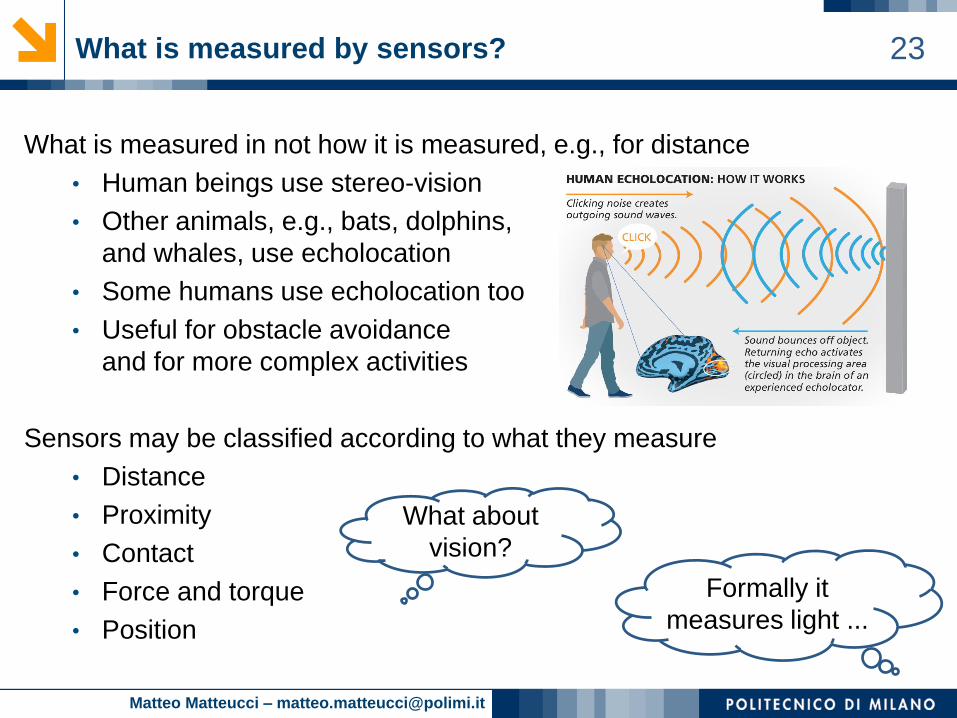
What is measured in not how it is measured, e.g., for distance
• Human beings use stereo-vision
• Other animals, e.g., bats, dolphins,
and whales, use echolocation
• Some humans use echolocation too
• Useful for obstacle avoidance
and for more complex activities
Sensors may be classified according to what they measure
• Distance
• Proximity
• Contact
• Force and torque
• Position
What about
vision?
Formally it
measures light ...
Matteo Matteucci – [email protected]
24Distance perception: time-of-flight telemeter
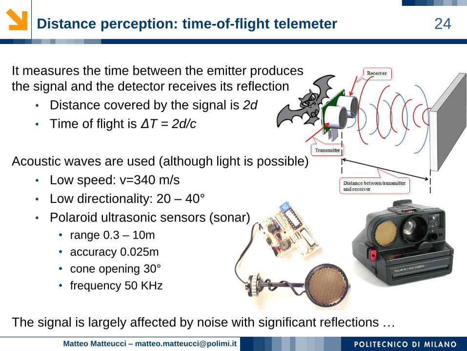
It measures the time between the emitter produces
the signal and the detector receives its reflection
• Distance covered by the signal is 2d
• Time of flight is ΔT = 2d/c
Acoustic waves are used (although light is possible)
• Low speed: v=340 m/s
• Low directionality: 20 – 40°
• Polaroid ultrasonic sensors (sonar)
• range 0.3 – 10m
• accuracy 0.025m
• cone opening 30°
• frequency 50 KHz
The signal is largely affected by noise with significant reflections …

Matteo Matteucci – [email protected]
25Issues with sonars
The range should be chosen
according to the application
They do not work in all conditions
• Sampling frequency trade-off
• Reflections against walls
• Small objects
• Soft objects
Rooms may look larger than expected at corners!
Matteo Matteucci – [email protected]
26Distance perception: reflective optosensors
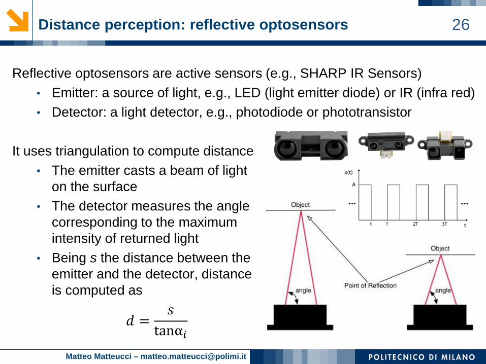
Reflective optosensors are active sensors (e.g., SHARP IR Sensors)
• Emitter: a source of light, e.g., LED (light emitter diode) or IR (infra red)
• Detector: a light detector, e.g., photodiode or phototransistor
It uses triangulation to compute distance
• The emitter casts a beam of light
on the surface
• The detector measures the angle
corresponding to the maximum
intensity of returned light
• Being s the distance between the
emitter and the detector, distance
is computed as
𝑑 =𝑠
tanα𝑖
Matteo Matteucci – [email protected]
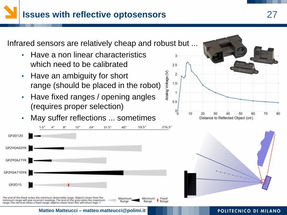
27Issues with reflective optosensors
Infrared sensors are relatively cheap and robust but ...
• Have a non linear characteristics
which need to be calibrated
• Have an ambiguity for short
range (should be placed in the robot)
• Have fixed ranges / opening angles
(requires proper selection)
• May suffer reflections ... sometimes
Matteo Matteucci – [email protected]
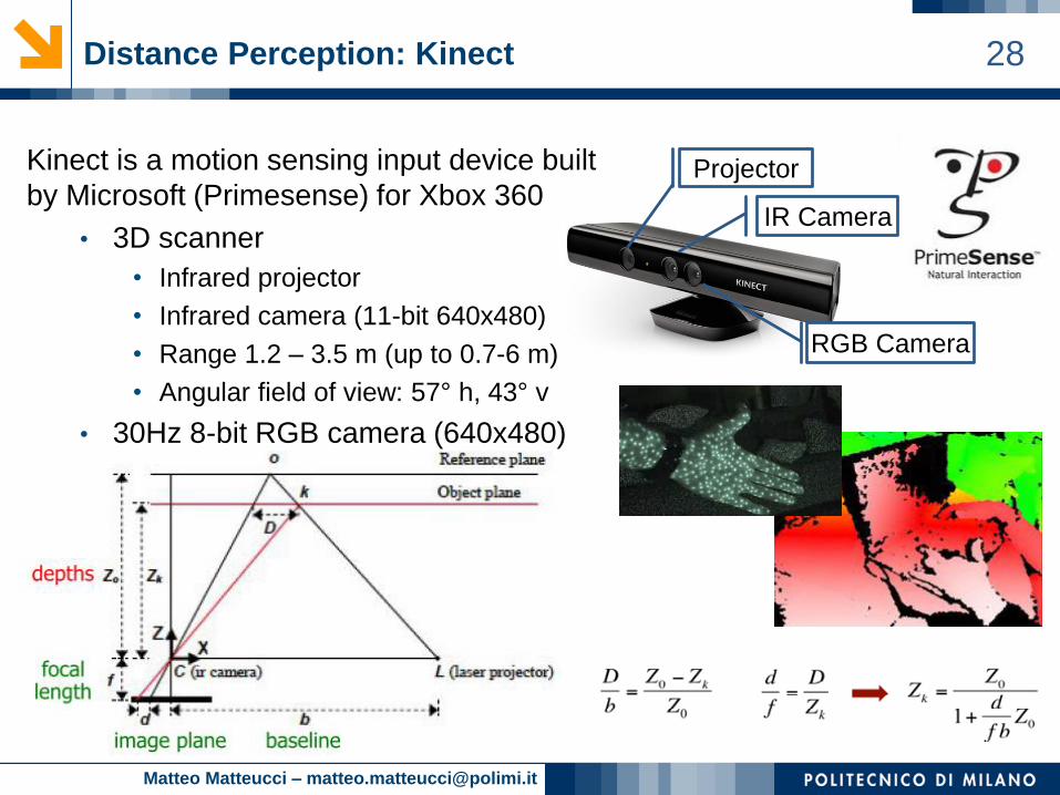
28Distance Perception: Kinect
Kinect is a motion sensing input device built
by Microsoft (Primesense) for Xbox 360
• 3D scanner
• Infrared projector
• Infrared camera (11-bit 640x480)
• Range 1.2 – 3.5 m (up to 0.7-6 m)
• Angular field of view: 57° h, 43° v
• 30Hz 8-bit RGB camera (640x480)
Projector
IR Camera
RGB Camera
Matteo Matteucci – [email protected]
29
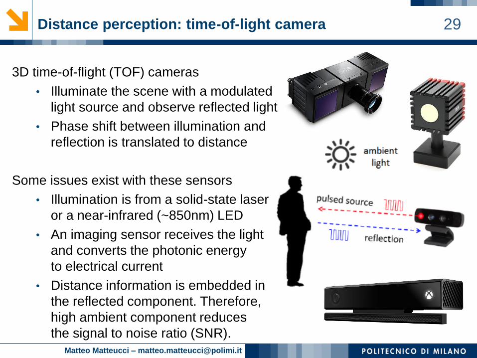
3D time-of-flight (TOF) cameras
• Illuminate the scene with a modulated
light source and observe reflected light
• Phase shift between illumination and
reflection is translated to distance
Some issues exist with these sensors
• Illumination is from a solid-state laser
or a near-infrared (~850nm) LED
• An imaging sensor receives the light
and converts the photonic energy
to electrical current
• Distance information is embedded in
the reflected component. Therefore,
high ambient component reduces
the signal to noise ratio (SNR).
Distance perception: time-of-light camera
Matteo Matteucci – [email protected]
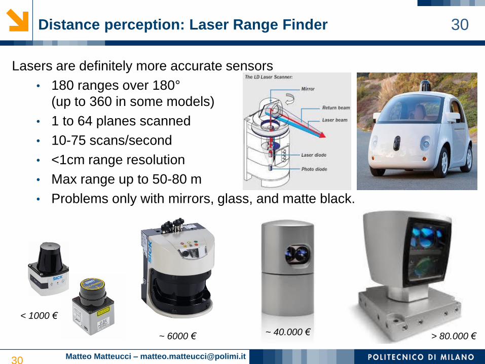
30Distance perception: Laser Range Finder
Lasers are definitely more accurate sensors
• 180 ranges over 180°
(up to 360 in some models)
• 1 to 64 planes scanned
• 10-75 scans/second
• <1cm range resolution
• Max range up to 50-80 m
• Problems only with mirrors, glass, and matte black.
30
< 1000 €
> 80.000 €~ 40.000 €~ 6000 €
Matteo Matteucci – [email protected]
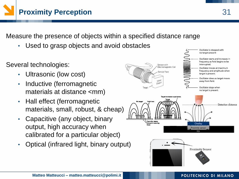
31Proximity Perception
Measure the presence of objects within a specified distance range
• Used to grasp objects and avoid obstacles
Several technologies:
• Ultrasonic (low cost)
• Inductive (ferromagnetic
materials at distance <mm)
• Hall effect (ferromagnetic
materials, small, robust, & cheap)
• Capacitive (any object, binary
output, high accuracy when
calibrated for a particular object)
• Optical (infrared light, binary output)
Matteo Matteucci – [email protected]
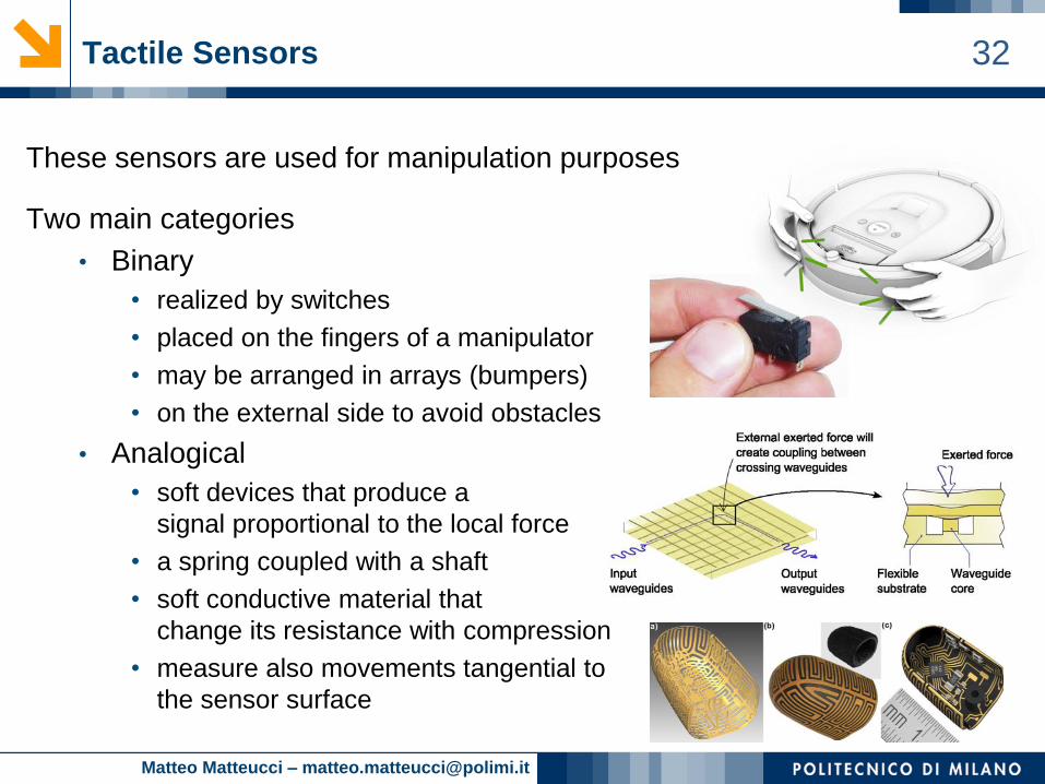
32Tactile Sensors
These sensors are used for manipulation purposes
Two main categories
• Binary
• realized by switches
• placed on the fingers of a manipulator
• may be arranged in arrays (bumpers)
• on the external side to avoid obstacles
• Analogical
• soft devices that produce a
signal proportional to the local force
• a spring coupled with a shaft
• soft conductive material that
change its resistance with compression
• measure also movements tangential to
the sensor surface
Matteo Matteucci – [email protected]
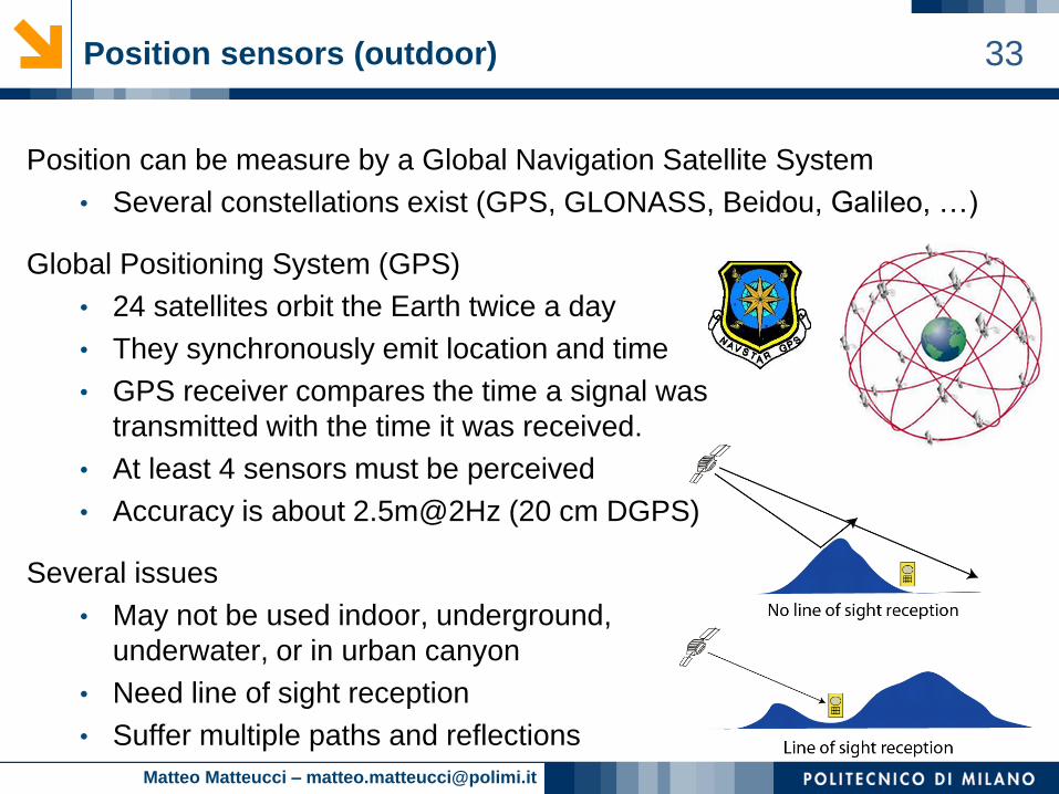
33Position sensors (outdoor)
Position can be measure by a Global Navigation Satellite System
• Several constellations exist (GPS, GLONASS, Beidou, Galileo, …)
Global Positioning System (GPS)
• 24 satellites orbit the Earth twice a day
• They synchronously emit location and time
• GPS receiver compares the time a signal was
transmitted with the time it was received.
• At least 4 sensors must be perceived
• Accuracy is about 2.5m@2Hz (20 cm DGPS)
Several issues
• May not be used indoor, underground,
underwater, or in urban canyon
• Need line of sight reception
• Suffer multiple paths and reflections
Matteo Matteucci – [email protected]
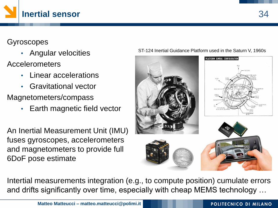
34Inertial sensor
Gyroscopes
• Angular velocities
Accelerometers
• Linear accelerations
• Gravitational vector
Magnetometers/compass
• Earth magnetic field vector
An Inertial Measurement Unit (IMU)
fuses gyroscopes, accelerometers
and magnetometers to provide full
6DoF pose estimate
Intertial measurements integration (e.g., to compute position) cumulate errors
and drifts significantly over time, especially with cheap MEMS technology …
ST-124 Inertial Guidance Platform used in the Saturn V, 1960s
Matteo Matteucci – [email protected]
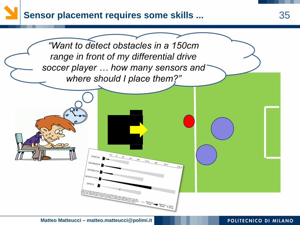
35Sensor placement requires some skills ...
“Want to detect obstacles in a 150cm
range in front of my differential drive
soccer player … how many sensors and
where should I place them?”