70
© Copyright 2006-2008 ABB. All rights reserved. Operating manual Machine Tending PowerPac RobotStudio 5.10 Document ID: 3HAC026808-001 Revision: E

© C
opyr
ight
200
6-20
08 A
BB
. All
right
s res
erve
d.
Operating manualMachine Tending PowerPac
RobotStudio 5.10
Document ID: 3HAC026808-001
Revision: E

© C
opyr
ight
200
6-20
08 A
BB
. All
right
s res
erve
d.
The information in this manual is subject to change without notice and should not be construed as a commitment by ABB. ABB assumes no responsibility for any errors that may appear in this manual.Except as may be expressly stated anywhere in this manual, nothing herein shall be construed as any kind of guarantee or warranty by ABB for losses, damages to persons or property, fitness for a specific purpose or the like.In no event shall ABB be liable for incidental or consequential damages arising from use of this manual and products described herein.This manual and parts thereof must not be reproduced or copied without ABB’s written permission, and contents thereof must not be imparted to a third party nor be used for any unauthorized purpose. Contravention will be prosecuted.Additional copies of this manual may be obtained from ABB at its then current charge.
© Copyright 2006 -2008 ABB All right reserved.
ABB RoboticsSE-721 68 Västerås
Sweden
Table of Contents©
Cop
yrig
ht 2
006-
2008
AB
B. A
ll rig
hts r
eser
ved.
Overview ..........................................................................................................................................5
1 Introduction 71.1 Overview of Machine Tending PowerPac..................................................................................71.2 Installing Machine Tending PowerPac.....................................................................................10
2 Working with the Machine Tending PowerPac 152.1 Getting started ..........................................................................................................................152.2 User interface ...........................................................................................................................192.3 Cell Wizard...............................................................................................................................23
2.3.1 The Cell Wizard interface ..............................................................................................232.3.2 Creating a cell with the Cell Wizard ..............................................................................24
2.4 Process view ...........................................................................................................................292.4.1 Overview ........................................................................................................................292.4.2 Editing cell components .................................................................................................312.4.3 Editing stations ...............................................................................................................352.4.4 Editing tools ...................................................................................................................422.4.5 Editing parts ...................................................................................................................432.4.6 Editing auxiliary devices ................................................................................................442.4.7 Defining a cycle .............................................................................................................472.4.8 Auto-placing Cell Components ......................................................................................49
2.5 Running a Simulation...............................................................................................................512.6 Statistics Information ...............................................................................................................532.7 Customizing Cell Components.................................................................................................582.8 Exporting and Importing Templates.........................................................................................65
3

Table of Contents
© C
opyr
ight
200
6-20
08 A
BB
. All
right
s res
erve
d.
4

Overview
© C
opyr
ight
200
6-20
08 A
BB
. All
right
s res
erve
d.
Overview
About this manualThis manual is to be used when working with Machine Tending PowerPac.
Who should read this manual?Machine Tending PowerPac can be set up with different user levels:
• Sales engineers can use this tool for demonstrating robot cell to customers.
• Project engineers can use this tool to minimize project risks by being able to select the optimum equipment and layout for an installation.
• RobotStudio experts can use both the Machine Tending PowerPac and RobotStudio base function for detailed engineering solutions.
Organization of chapters
References
Revisions
Chapter Contents
1. Describes the key features and installation of Machine Tending PowerPac.
2. Describes how to work with Machine Tending PowerPac.
Reference Document Id
Operating manual - RobotStudio 3HAC028932-001
Revision Description
E New section Exporting and Importing Templates added.
53HAC026808-001 Revision: E

Overview
© C
opyr
ight
200
6-20
08 A
BB
. All
right
s res
erve
d.
6 3HAC026808-001 Revision: E

1 Introduction1.1. Overview of Machine Tending PowerPac
© C
opyr
ight
200
6-20
08 A
BB
. All
right
s res
erve
d.
1 Introduction1.1. Overview of Machine Tending PowerPac
Machine Tending PowerPacMachine Tending PowerPac is simulation software that demonstrates the ability of ABB robots in machine tending applications. The Machine Tending PowerPac:
• Provides a five step wizard to create a work cell.
• Gives an estimation of the cycle time (both robot cycle and machine cycle) through the statistics function.
• Provides the cell layout and footprint after the first simulation.
• Identifies any post-processes that a robot can conduct while the machine is moulding a part.
RobotStudioRobotStudio is the programming and simulation software, which enables the users to perform tasks such as training programming and configuration offline - without disturbing production. Machine Tending PowerPac is an add-in to RobotStudio. It is fully integrated with RobotStudio. A user can use RobotStudio base functions together with Machine Tending PowerPac.
Refer to Operating manual - RobotStudio.
73HAC026808-001 Revision: E
Continues on next page
1 Introduction1.1. Overview of Machine Tending PowerPac
© C
opyr
ight
200
6-20
08 A
BB
. All
right
s res
erve
d.
Continued
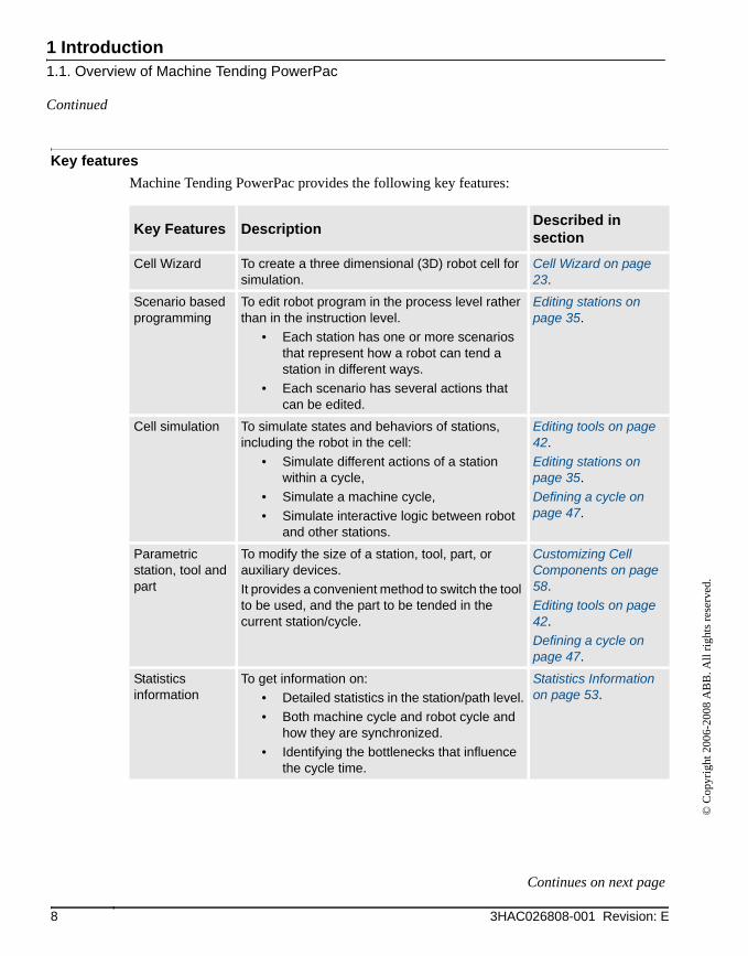
Key featuresMachine Tending PowerPac provides the following key features:
Key Features Description Described in section
Cell Wizard To create a three dimensional (3D) robot cell for simulation.
Cell Wizard on page 23.
Scenario based programming
To edit robot program in the process level rather than in the instruction level.
• Each station has one or more scenarios that represent how a robot can tend a station in different ways.
• Each scenario has several actions that can be edited.
Editing stations on page 35.
Cell simulation To simulate states and behaviors of stations, including the robot in the cell:
• Simulate different actions of a station within a cycle,
• Simulate a machine cycle,• Simulate interactive logic between robot
and other stations.
Editing tools on page 42.Editing stations on page 35.Defining a cycle on page 47.
Parametric station, tool and part
To modify the size of a station, tool, part, or auxiliary devices.It provides a convenient method to switch the tool to be used, and the part to be tended in the current station/cycle.
Customizing Cell Components on page 58.Editing tools on page 42.Defining a cycle on page 47.
Statistics information
To get information on:• Detailed statistics in the station/path level.• Both machine cycle and robot cycle and
how they are synchronized.• Identifying the bottlenecks that influence
the cycle time.
Statistics Information on page 53.
8 3HAC026808-001 Revision: E
Continues on next page
1 Introduction1.1. Overview of Machine Tending PowerPac
© C
opyr
ight
200
6-20
08 A
BB
. All
right
s res
erve
d.
Continued
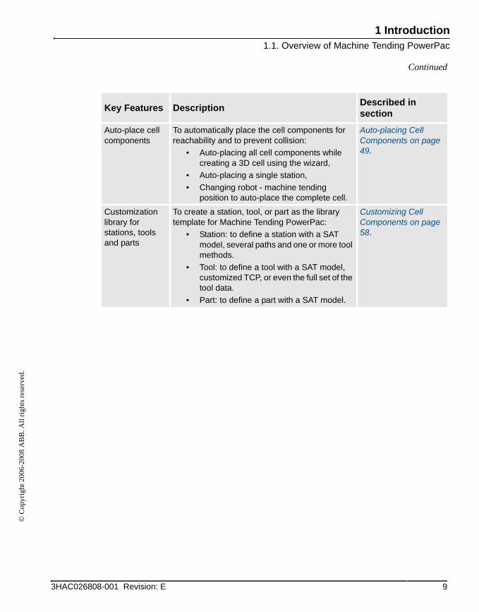
Auto-place cell components
To automatically place the cell components for reachability and to prevent collision:
• Auto-placing all cell components while creating a 3D cell using the wizard,
• Auto-placing a single station,• Changing robot - machine tending
position to auto-place the complete cell.
Auto-placing Cell Components on page 49.
Customization library for stations, tools and parts
To create a station, tool, or part as the library template for Machine Tending PowerPac:
• Station: to define a station with a SAT model, several paths and one or more tool methods.
• Tool: to define a tool with a SAT model, customized TCP, or even the full set of the tool data.
• Part: to define a part with a SAT model.
Customizing Cell Components on page 58.
Key Features Description Described in section
93HAC026808-001 Revision: E
1 Introduction1.2. Installing Machine Tending PowerPac
© C
opyr
ight
200
6-20
08 A
BB
. All
right
s res
erve
d.
1.2. Installing Machine Tending PowerPac
OverviewThis section describes the installation process.
PrerequisitesTo start the installation process, the following must be available:
• A computer that fulfils or exceeds the system requirements.
• A log in account with administrator rights on the computer.
• RobotStudio installed on the computer.
• Machine Tending PowerPac installation package.
System requirementsTo work with Machine Tending PowerPac, the following are required:
Recommended hardware• CPU: 2.0 GHz Intel Pentium 4 or faster processor
• Memory: 1 GB RAM or more
• Available disk space: 5+ GB on the system disk, 250+ MB on the installation disk
• Graphics card: High performance OpenGL-compatible graphics card with the corresponding up-to-date drivers installed
• Screen resolution: 1280 x 1024 pixels (Recommended)
• Colors: 256 or higher
• DPI: Normal size (96 dpi)
• Mouse: Three button mouse
Software requirements• Microsoft Windows XP Professional with Service Pack 2, or
• Microsoft Windows Vista - Business or higher
NOTE!Firewall for Windows XP SP2 may block a few features necessary to run RobotStudio and RobotStudio Online properly. Make sure to unblock these features when required (Industrial Robot Discovery Server, RobotStudio StudioAppFramework module, Virtual Robot
10 3HAC026808-001 Revision: E
Continues on next page

1 Introduction1.2. Installing Machine Tending PowerPac
© C
opyr
ight
200
6-20
08 A
BB
. All
right
s res
erve
d.
Continued
Controller (all published by ABB)). The block status of some programs can be viewed and changed through Start > Settings > Control Panel > Windows Security Center > Windows Firewall in the PC. For details, refer to www.microsoft.com.
NOTE!Windows service-packs can be downloaded from www.microsoft.com.
Installing the Machine Tending PowerPac
Action
1. Browse to the Machine Tending PowerPac installation package and double-click the setup.exe file.Installation wizard is displayed.
2. Click Next to continue installation.
pic0001
113HAC026808-001 Revision: E
Continues on next page

1 Introduction1.2. Installing Machine Tending PowerPac
© C
opyr
ight
200
6-20
08 A
BB
. All
right
s res
erve
d.
Continued
3. Read the information carefully. Click Next.
pic0002
4. Click Next to confirm installation.
pic0003
Action
12 3HAC026808-001 Revision: E
Continues on next page

1 Introduction1.2. Installing Machine Tending PowerPac
© C
opyr
ight
200
6-20
08 A
BB
. All
right
s res
erve
d.
Continued
5. When the installation is complete, click Close to exit the wizard.
pic0004
Action
133HAC026808-001 Revision: E

1 Introduction1.2. Installing Machine Tending PowerPac
© C
opyr
ight
200
6-20
08 A
BB
. All
right
s res
erve
d.
14 3HAC026808-001 Revision: E
2 Working with the Machine Tending PowerPac2.1. Getting started
© C
opyr
ight
200
6-20
08 A
BB
. All
right
s res
erve
d.
2 Working with the Machine Tending PowerPac2.1. Getting started
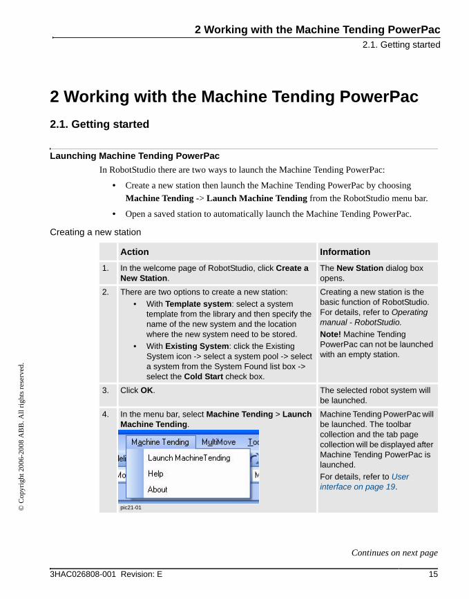
Launching Machine Tending PowerPacIn RobotStudio there are two ways to launch the Machine Tending PowerPac:
• Create a new station then launch the Machine Tending PowerPac by choosing Machine Tending -> Launch Machine Tending from the RobotStudio menu bar.
• Open a saved station to automatically launch the Machine Tending PowerPac.
Creating a new station
Action Information
1. In the welcome page of RobotStudio, click Create a New Station.
The New Station dialog box opens.
2. There are two options to create a new station:• With Template system: select a system
template from the library and then specify the name of the new system and the location where the new system need to be stored.
• With Existing System: click the Existing System icon -> select a system pool -> select a system from the System Found list box -> select the Cold Start check box.
Creating a new station is the basic function of RobotStudio. For details, refer to Operating manual - RobotStudio.Note! Machine Tending PowerPac can not be launched with an empty station.
3. Click OK. The selected robot system will be launched.
4. In the menu bar, select Machine Tending > Launch Machine Tending.
pic21-01
Machine Tending PowerPac will be launched. The toolbar collection and the tab page collection will be displayed after Machine Tending PowerPac is launched.For details, refer to User interface on page 19.
153HAC026808-001 Revision: E
Continues on next page
2 Working with the Machine Tending PowerPac2.1. Getting started
© C
opyr
ight
200
6-20
08 A
BB
. All
right
s res
erve
d.
Continued
Opening a saved station
Closing Machine Tending PowerPac
Action Information
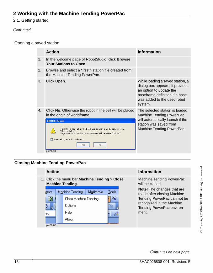
1. In the welcome page of RobotStudio, click Browse Your Stations to Open.
2. Browse and select a *.rsstn station file created from the Machine Tending PowerPac.
3. Click Open. While loading a saved station, a dialog box appears. It provides an option to update the baseframe definition if a base was added to the used robot system.
4. Click No. Otherwise the robot in the cell will be placed in the origin of worldframe.
pic21-03
The selected station is loaded. Machine Tending PowerPac will automatically launch if the station was saved from Machine Tending PowerPac.
Action Information
1. Click the menu bar Machine Tending > Close Machine Tending.
pic21-02
Machine Tending PowerPac will be closed. Note! The changes that are made after closing Machine Tending PowerPac can not be recognized in the Machine Tending PowerPac environ-ment.
16 3HAC026808-001 Revision: E
Continues on next page
2 Working with the Machine Tending PowerPac2.1. Getting started
© C
opyr
ight
200
6-20
08 A
BB
. All
right
s res
erve
d.
Continued
Selecting Options
Action Information
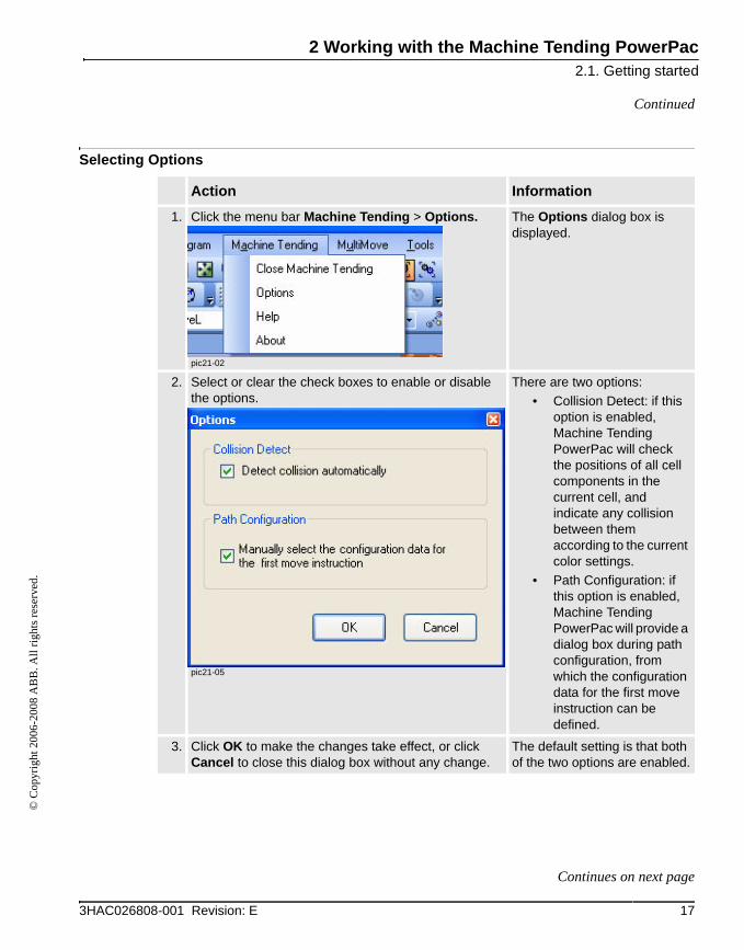
1. Click the menu bar Machine Tending > Options.
pic21-02
The Options dialog box is displayed.
2. Select or clear the check boxes to enable or disable the options.
pic21-05
There are two options:• Collision Detect: if this
option is enabled, Machine Tending PowerPac will check the positions of all cell components in the current cell, and indicate any collision between them according to the current color settings.
• Path Configuration: if this option is enabled, Machine Tending PowerPac will provide a dialog box during path configuration, from which the configuration data for the first move instruction can be defined.
3. Click OK to make the changes take effect, or click Cancel to close this dialog box without any change.
The default setting is that both of the two options are enabled.
173HAC026808-001 Revision: E
Continues on next page
2 Working with the Machine Tending PowerPac2.1. Getting started
© C
opyr
ight
200
6-20
08 A
BB
. All
right
s res
erve
d.
Continued
NOTE!In RobotStudio, the station means the entire work cell including all required equipment. But in Machine Tending PowerPac, the concept of station is defined according to the application. A station includes:
• A geometrical model,
• A work object attached to the geometrical model,
• Two or more robot targets based on the station work object,
• Two or more paths defines the robot motion when robot tends the station,
• One or more tool actions defines the tool method - optional,
• One or more I/O signal actions defines the station logic - optional.
18 3HAC026808-001 Revision: E
2 Working with the Machine Tending PowerPac2.2. User interface
© C
opyr
ight
200
6-20
08 A
BB
. All
right
s res
erve
d.
2.2. User interface
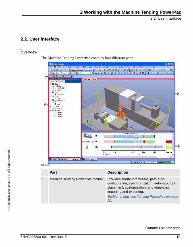
OverviewThe Machine Tending PowerPac contains four different parts.
pic22-02
Part Description
1 Machine Tending PowerPac toolbar Provides shortcut to wizard, path auto-configuration, synchronization, automatic cell placement, customization, and templates importing and exporting.Toolbar of Machine Tending PowerPac on page 20.
193HAC026808-001 Revision: E
Continues on next page

2 Working with the Machine Tending PowerPac2.2. User interface
© C
opyr
ight
200
6-20
08 A
BB
. All
right
s res
erve
d.
Continued
Toolbar of Machine Tending PowerPacWhen launching the Machine Tending PowerPac, an exclusive toolbar for the Machine Tending PowerPac appears.
2. Machine Tending tab collection There are two tabs:• Process view: used to access most of the
functions of Machine Tending PowerPac. Refer to Process view on page 29.
• Statistics: used to view statistics, and launch run time information analysis during simulation. Refer to Statistics Information on page 53.
3. 3D graphical view To view 3D robot cell and simulation.
4. Analysis window To display the runtime information for both machine cycles and robot cycles, and identify the bottlenecks of the production cycle. Refer to Viewing the information in the analysis window on page 54.
Part Description
Button Description
Launch Wizard
pic2204
Launches the work cell setup wizard.
Configure the Path and Synchronize with Virtual Controller
pic2205
Performs an automatic path configuration for all move instruc-tions according to the active cycle settings, and synchronize the current cell settings to the virtual controller to generate RAPID program for simulation. Furthermore performs simulation set up automatically.
Synchronize with Virtual Controller
pic2209
Synchronizes the current cell setting to the virtual controller to generate RAPID program for simulation, and performs simulation set up automatically.
20 3HAC026808-001 Revision: E
Continues on next page

2 Working with the Machine Tending PowerPac2.2. User interface
© C
opyr
ight
200
6-20
08 A
BB
. All
right
s res
erve
d.
Continued
Operating the Graphics view with the mouseThe Graphics window is RobotStudio base environment. For details, refer to Operating manual - RobotStudio.
SelectPlace the mouse pointer above the Graphics window and click to select objects.
pic2011
Auto-place Cell Component
pic2207
Auto-place cell components so that there is no collision between cell components and all targets are reachable:
• Auto-placing all cell components while creating a 3D cell using the wizard.
• Auto-placing a single station.• Changing the robot position with respect to the
machine position type and hence auto placing whole cell.
Customize Cell Components
pic2208
Launches the customize object wizard to create a station, tool or part as the library item for Machine Tending PowerPac.
Export Template
pic2210
Exports templates to cab files to:• backup the customized templates.• share the customized templates with other Machine
Tending PowerPac users.For details, refer to Exporting and Importing Templates on page 65.
Import Template
pic2211
Imports cab files that were exported using Machine Tending PowerPac before.For details, refer to Exporting and Importing Templates on page 65.
Button Description
213HAC026808-001 Revision: E
Continues on next page

2 Working with the Machine Tending PowerPac2.2. User interface
© C
opyr
ight
200
6-20
08 A
BB
. All
right
s res
erve
d.
Continued
RotateUse these buttons to rotate the station around the current view center.
Using a 3-button mouse: Click and hold down the middle and the right mouse button.
Using a 2-button mouse: Click and hold down the right mouse button and the CTRL and SHIFT keys.
pic2012
PanDrag to pan the view. Hold down left mouse button and the CTRL key.
pic2013
ZoomDrag to the left to zoom out, drag to the right to zoom in.
Using a 3-button mouse: Click and hold down the middle mouse button.
Using a 2-button mouse: Click and hold down the right mouse button and the CTRL key.
pic2014
22 3HAC026808-001 Revision: E
2 Working with the Machine Tending PowerPac2.3.1. The Cell Wizard interface
© C
opyr
ight
200
6-20
08 A
BB
. All
right
s res
erve
d.
2.3 Cell Wizard
2.3.1. The Cell Wizard interface
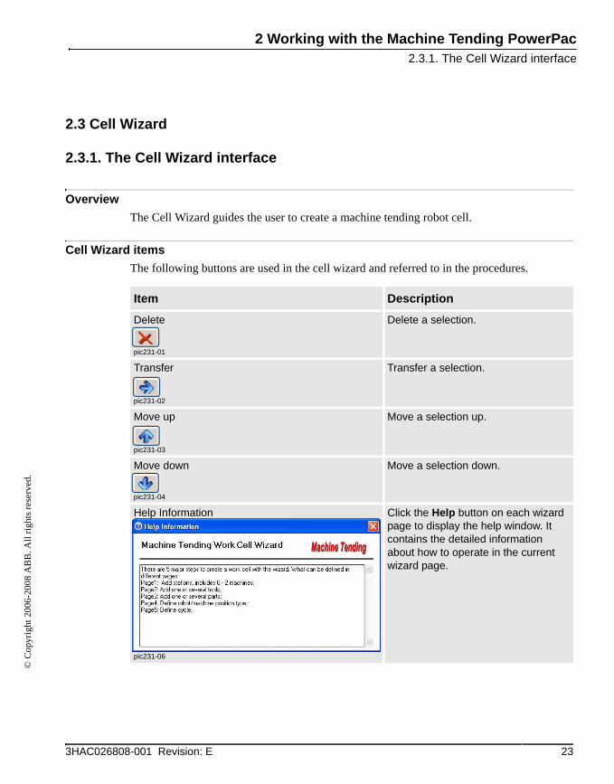
OverviewThe Cell Wizard guides the user to create a machine tending robot cell.
Cell Wizard itemsThe following buttons are used in the cell wizard and referred to in the procedures.
Item Description
Delete
pic231-01
Delete a selection.
Transfer
pic231-02
Transfer a selection.
Move up
pic231-03
Move a selection up.
Move down
pic231-04
Move a selection down.
Help Information
pic231-06
Click the Help button on each wizard page to display the help window. It contains the detailed information about how to operate in the current wizard page.
233HAC026808-001 Revision: E

2 Working with the Machine Tending PowerPac2.3.2. Creating a cell with the Cell Wizard
© C
opyr
ight
200
6-20
08 A
BB
. All
right
s res
erve
d.
2.3.2. Creating a cell with the Cell Wizard
Creating a cellThe Cell Wizard has five steps. The table below describes the wizard.
Action Information
1. StartClick Launch Wizard on the Machine Tending PowerPac toolbar collection.
pic232-01
Click Next.
The welcome page of the wizard is displayed.
2. Add station(s) to the cell.• Select a station from the library, click
Transfer to add the station to the cell.• Double click the station in Stations in Cell
list box, and enter a valid name to rename the station if necessary.
• Repeat the previous steps to add more stations.
pic232-02
Click Next.
There are recommended IMMs for different robot systems, which are marked with green in the list.This wizard page is used to add both machines and other types of stations to a cell. It is possible to add more than one station of the same type.If the list of predefined stations does not contain the required station, it is possible to add a new station type as a library item by using Customize Cell Components. Refer to Customizing Cell Components on page 58 for more information.Note! The maximum number of machines that can be added to a cell is two. There is no limitation to add stations other than machines.
24 3HAC026808-001 Revision: E
Continues on next page
2 Working with the Machine Tending PowerPac2.3.2. Creating a cell with the Cell Wizard
© C
opyr
ight
200
6-20
08 A
BB
. All
right
s res
erve
d.
Continued
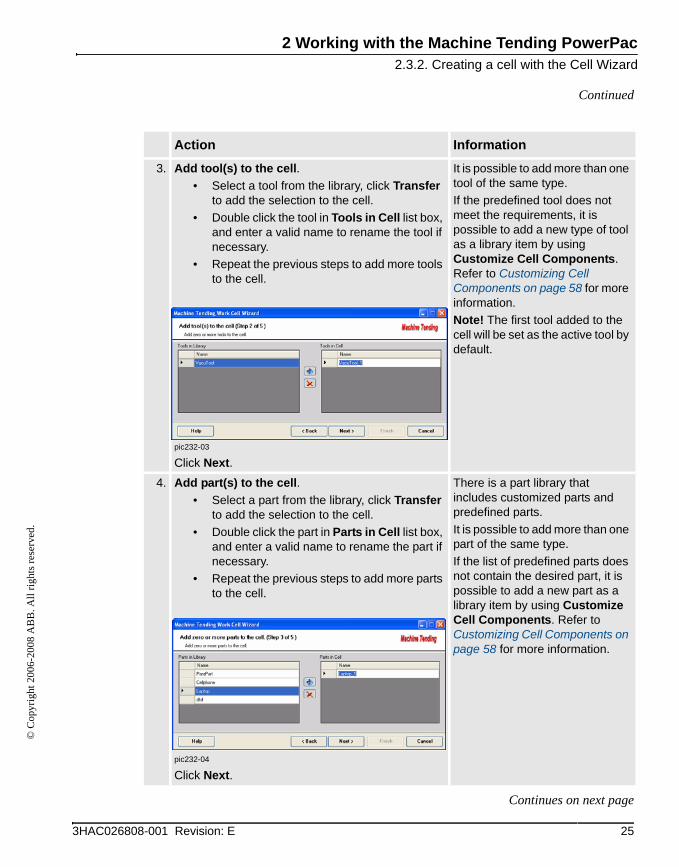
3. Add tool(s) to the cell.• Select a tool from the library, click Transfer
to add the selection to the cell.• Double click the tool in Tools in Cell list box,
and enter a valid name to rename the tool if necessary.
• Repeat the previous steps to add more tools to the cell.
pic232-03
Click Next.
It is possible to add more than one tool of the same type.If the predefined tool does not meet the requirements, it is possible to add a new type of tool as a library item by using Customize Cell Components. Refer to Customizing Cell Components on page 58 for more information.Note! The first tool added to the cell will be set as the active tool by default.
4. Add part(s) to the cell.• Select a part from the library, click Transfer
to add the selection to the cell.• Double click the part in Parts in Cell list box,
and enter a valid name to rename the part if necessary.
• Repeat the previous steps to add more parts to the cell.
pic232-04
Click Next.
There is a part library that includes customized parts and predefined parts.It is possible to add more than one part of the same type.If the list of predefined parts does not contain the desired part, it is possible to add a new part as a library item by using Customize Cell Components. Refer to Customizing Cell Components on page 58 for more information.
Action Information
253HAC026808-001 Revision: E
Continues on next page

2 Working with the Machine Tending PowerPac2.3.2. Creating a cell with the Cell Wizard
© C
opyr
ight
200
6-20
08 A
BB
. All
right
s res
erve
d.
Continued
5. Define Cell Placement.• Click Robot/Machine Position Type list to
choose a robot position type relative to the machine.
• All the stations in cell are listed in the Stations in Cell table.
• Select the Add fence and/or Add Robot base check box (s) to add a fence and/or a robot base to the cell.
pic232-05
Click Next.
There can be different situations. If there is:
• no machine in the cell, there is no need to consider robot position relative to IMM,
• one machine in the cell, there are three different ways to position the robot, Front of Machine, Back of Machine (default), On top of Machine,
• two machines in the cell, only one robot position type is available.
An image will show what the robot position type looks like.
Other stations will automatically be placed relative to the robot so that they are reachable and there will not be any collisions.
Action Information
26 3HAC026808-001 Revision: E
Continues on next page
2 Working with the Machine Tending PowerPac2.3.2. Creating a cell with the Cell Wizard
© C
opyr
ight
200
6-20
08 A
BB
. All
right
s res
erve
d.
Continued
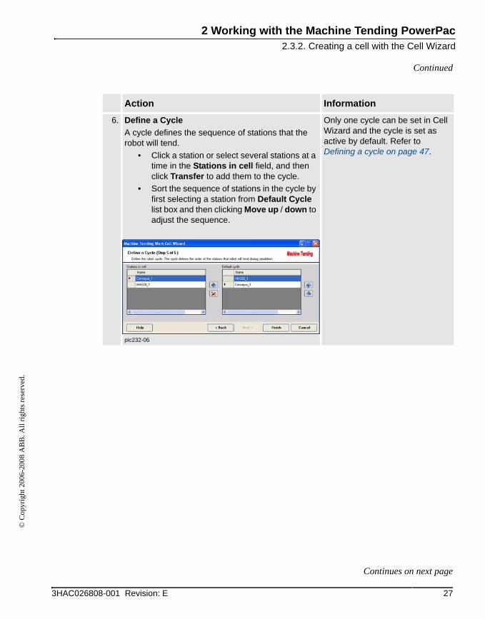
6. Define a CycleA cycle defines the sequence of stations that the robot will tend.
• Click a station or select several stations at a time in the Stations in cell field, and then click Transfer to add them to the cycle.
• Sort the sequence of stations in the cycle by first selecting a station from Default Cycle list box and then clicking Move up / down to adjust the sequence.
pic232-06
Only one cycle can be set in Cell Wizard and the cycle is set as active by default. Refer to Defining a cycle on page 47.
Action Information
273HAC026808-001 Revision: E
Continues on next page

2 Working with the Machine Tending PowerPac2.3.2. Creating a cell with the Cell Wizard
© C
opyr
ight
200
6-20
08 A
BB
. All
right
s res
erve
d.
Continued
7. Click Finish, the Machine Tending PowerPac will:• add stations with default geometrical
parameters, targets and paths to the 3D cell,• add tools to the 3D cell. If there are more
than one tool in the cell, the active tool will be attached to the robot, the others will be placed next to the cell,
• add parts to the 3D cell,• position all the stations including the
machine(s) in the cell for reachability and to prevent collision.
After that, a message box appears asking "Do you want to do automatic path configuration and then synchronize with Virtual Controller?". Click Yes, the Machine Tending PowerPac will:
• Configure paths.• Synchronize all the settings to virtual
controller.Click No, it will take a few seconds to build the 3D cell. The path configuration and synchronization can be executed with the Machine Tending PowerPac toolbar collection.
It is possible to edit the cell from the Process View, refer to section Process view on page 29. After the cell is created, simulation can be ran after necessary operations, refer to Running a Simulation on page 51.
Action Information
28 3HAC026808-001 Revision: E
2 Working with the Machine Tending PowerPac2.4.1. Overview
© C
opyr
ight
200
6-20
08 A
BB
. All
right
s res
erve
d.
2.4 Process view
2.4.1. Overview
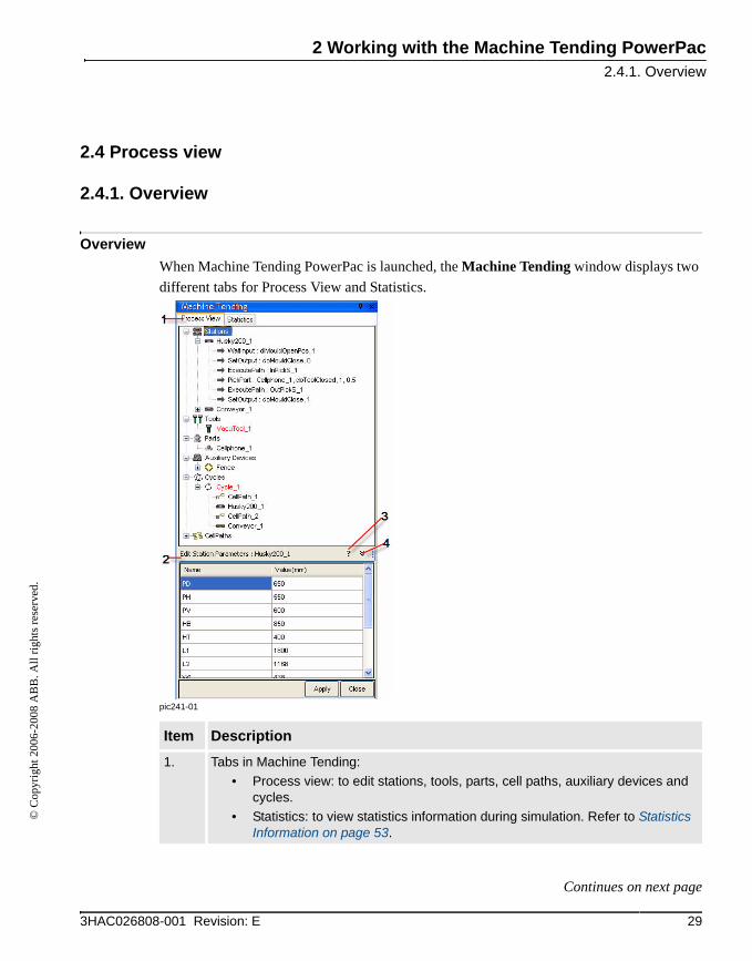
OverviewWhen Machine Tending PowerPac is launched, the Machine Tending window displays two different tabs for Process View and Statistics.
pic241-01
Item Description
1. Tabs in Machine Tending:• Process view: to edit stations, tools, parts, cell paths, auxiliary devices and
cycles.• Statistics: to view statistics information during simulation. Refer to Statistics
Information on page 53.
293HAC026808-001 Revision: E
Continues on next page
2 Working with the Machine Tending PowerPac2.4.1. Overview
© C
opyr
ight
200
6-20
08 A
BB
. All
right
s res
erve
d.
Continued
2. Editing window: to modify the cell components based on the selection from the browser.
3. Information: click this button to show help information.
4. Hide editor: click this button to close the editing window.
Item Description
30 3HAC026808-001 Revision: E
2 Working with the Machine Tending PowerPac2.4.2. Editing cell components
© C
opyr
ight
200
6-20
08 A
BB
. All
right
s res
erve
d.
2.4.2. Editing cell components
ProceduresThis section describes the general operations available in the Process view tab page.
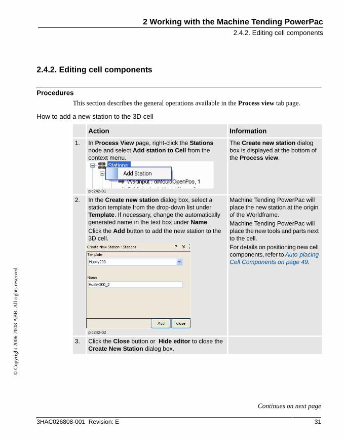
How to add a new station to the 3D cell
Action Information
1. In Process View page, right-click the Stations node and select Add station to Cell from the context menu.
pic242-01
The Create new station dialog box is displayed at the bottom of the Process view.
2. In the Create new station dialog box, select a station template from the drop-down list under Template. If necessary, change the automatically generated name in the text box under Name.Click the Add button to add the new station to the 3D cell.
pic242-02
Machine Tending PowerPac will place the new station at the origin of the Worldframe. Machine Tending PowerPac will place the new tools and parts next to the cell.For details on positioning new cell components, refer to Auto-placing Cell Components on page 49.
3. Click the Close button or Hide editor to close the Create New Station dialog box.
313HAC026808-001 Revision: E
Continues on next page

2 Working with the Machine Tending PowerPac2.4.2. Editing cell components
© C
opyr
ight
200
6-20
08 A
BB
. All
right
s res
erve
d.
Continued
How to delete a station
How to rename a station
Action Information
1. Right-click a station from the Stations collection in the Process View tab page. Then select Delete from the context menu.
pic242-03
The selected station will be deleted from the 3D cell.
Action Information
1. Right-click a station from the Stations collection in the Process View tab page, then select Rename from the context menu.
pic242-04
The name must meet the RAPID naming rules for a variable.In addition to the rules for RAPID variable naming, the station name must be less than or equal to 12 characters.Refer to Technical reference manual - RAPID overview for the naming rules of a RAPID variable
2. Enter a new name.
32 3HAC026808-001 Revision: E
Continues on next page
2 Working with the Machine Tending PowerPac2.4.2. Editing cell components
© C
opyr
ight
200
6-20
08 A
BB
. All
right
s res
erve
d.
Continued
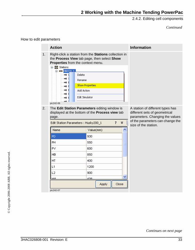
How to edit parameters
Action Information
1. Right-click a station from the Stations collection in the Process View tab page, then select Show Properties from the context menu.
pic242-06
2. The Edit Station Parameters editing window is displayed at the bottom of the Process view tab page.
pic242-07
A station of different types has different sets of geometrical parameters. Changing the values of the parameters can change the size of the station.
333HAC026808-001 Revision: E
Continues on next page

2 Working with the Machine Tending PowerPac2.4.2. Editing cell components
© C
opyr
ight
200
6-20
08 A
BB
. All
right
s res
erve
d.
Continued
3. Click the "?" in the upper right corner of the Edit station Parameter dialog box.
pic242-08
An image is displayed in a pop-up window to illustrate the meanings of different parameters.If there is no description for the selected item, no information available message is displayed. Click OK to close this box.
4. Click the Value (mm) text box to change one or more parameters, click the Apply button.
An invalid input is not accepted.
5. Click the Close button or Hide Editor button to close the editor.
When the editor is closed, the pop-up window will automatically be closed.
Action Information
34 3HAC026808-001 Revision: E
2 Working with the Machine Tending PowerPac2.4.3. Editing stations
© C
opyr
ight
200
6-20
08 A
BB
. All
right
s res
erve
d.
2.4.3. Editing stations
ProceduresThis section describes the procedures of editing stations.
How to add, delete, rename, and show properties of a stationFor details, refer to Editing cell components on page 31.
353HAC026808-001 Revision: E
Continues on next page
2 Working with the Machine Tending PowerPac2.4.3. Editing stations
© C
opyr
ight
200
6-20
08 A
BB
. All
right
s res
erve
d.
Continued
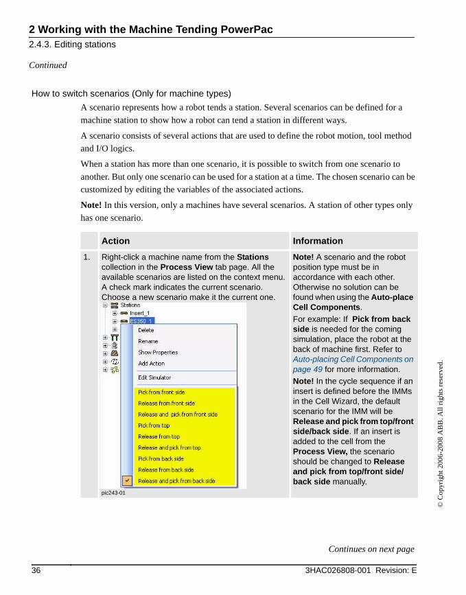
How to switch scenarios (Only for machine types)A scenario represents how a robot tends a station. Several scenarios can be defined for a machine station to show how a robot can tend a station in different ways.
A scenario consists of several actions that are used to define the robot motion, tool method and I/O logics.
When a station has more than one scenario, it is possible to switch from one scenario to another. But only one scenario can be used for a station at a time. The chosen scenario can be customized by editing the variables of the associated actions.
Note! In this version, only a machines have several scenarios. A station of other types only has one scenario.
Action Information
1. Right-click a machine name from the Stations collection in the Process View tab page. All the available scenarios are listed on the context menu. A check mark indicates the current scenario. Choose a new scenario make it the current one.
pic243-01
Note! A scenario and the robot position type must be in accordance with each other. Otherwise no solution can be found when using the Auto-place Cell Components.For example: If Pick from back side is needed for the coming simulation, place the robot at the back of machine first. Refer to Auto-placing Cell Components on page 49 for more information.Note! In the cycle sequence if an insert is defined before the IMMs in the Cell Wizard, the default scenario for the IMM will be Release and pick from top/front side/back side. If an insert is added to the cell from the Process View, the scenario should be changed to Release and pick from top/front side/back side manually.
36 3HAC026808-001 Revision: E
Continues on next page
2 Working with the Machine Tending PowerPac2.4.3. Editing stations
© C
opyr
ight
200
6-20
08 A
BB
. All
right
s res
erve
d.
Continued
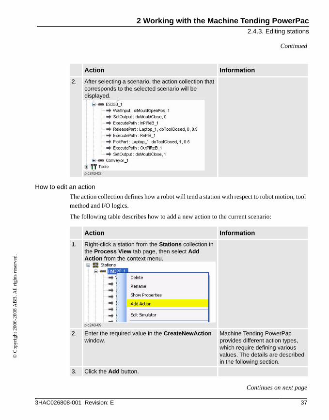
How to edit an actionThe action collection defines how a robot will tend a station with respect to robot motion, tool method and I/O logics.
The following table describes how to add a new action to the current scenario:
2. After selecting a scenario, the action collection that corresponds to the selected scenario will be displayed.
pic243-02
Action Information
Action Information
1. Right-click a station from the Stations collection in the Process View tab page, then select Add Action from the context menu.
pic243-09
2. Enter the required value in the CreateNewAction window.
Machine Tending PowerPac provides different action types, which require defining various values. The details are described in the following section.
3. Click the Add button.
373HAC026808-001 Revision: E
Continues on next page

2 Working with the Machine Tending PowerPac2.4.3. Editing stations
© C
opyr
ight
200
6-20
08 A
BB
. All
right
s res
erve
d.
Continued
The following table describes how to edit an existing action in the current scenario:
Action Information
1. Right-click an action item, select the Show Properties.
The action editor is displayed at the bottom of Process view tab page.
2. Enter the required value, click the Apply button.
38 3HAC026808-001 Revision: E
Continues on next page
2 Working with the Machine Tending PowerPac2.4.3. Editing stations
© C
opyr
ight
200
6-20
08 A
BB
. All
right
s res
erve
d.
Continued
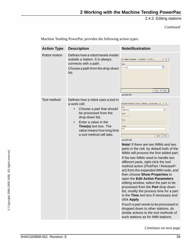
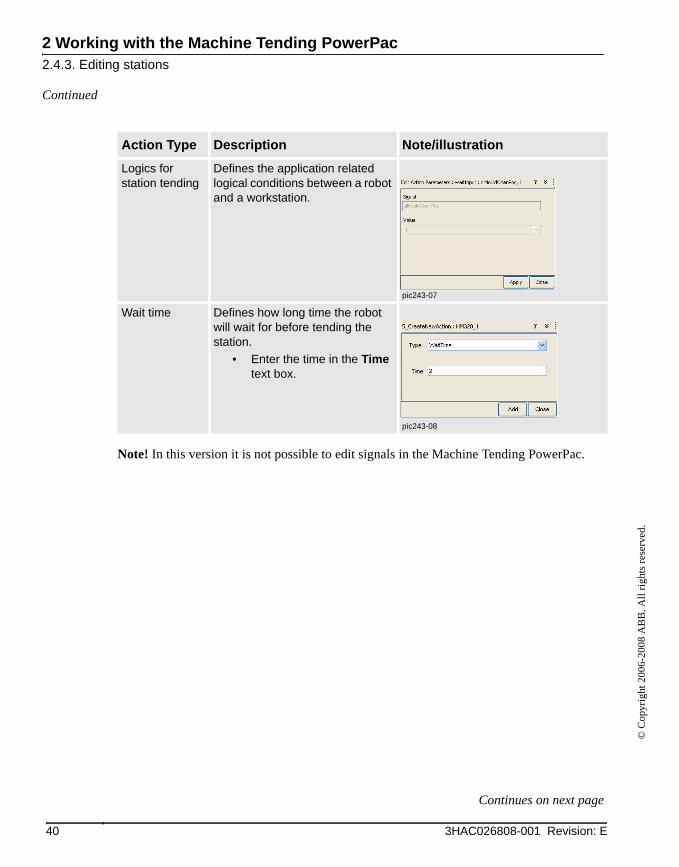
Machine Tending PowerPac provides the following action types:
Action Type Description Note/illustration
Robot motion Defines how a robot travels inside/ outside a station. It is always connects with a path.Choose a path from the drop-down list.
pic243-05
Tool method Defines how a robot uses a tool in a work cell.
• Choose a part that should be processed from the drop-down list,
• Enter a value in the Time(s) text box. The value means how long time a tool method will take.
pic243-06
Note! If there are two IMMs and two parts in the cell, by default both of the IMMs will process the first added part.If the two IMMs need to handle two different parts, right-click the tool method action (PickPart / ReleaseP-art) from the expanded IMM node, and then choose Show Properties to open the Edit Action Parameters editing window, select the part to be processed from the Part drop down list, modify the process time for a part in the Time text box if necessary and click Apply.If such a part needs to be processed or dropped down to other stations, do similar actions to the tool methods of such stations as for IMM stations.
393HAC026808-001 Revision: E
Continues on next page
2 Working with the Machine Tending PowerPac2.4.3. Editing stations
© C
opyr
ight
200
6-20
08 A
BB
. All
right
s res
erve
d.
Continued
Note! In this version it is not possible to edit signals in the Machine Tending PowerPac.
Logics for station tending
Defines the application related logical conditions between a robot and a workstation.
pic243-07
Wait time Defines how long time the robot will wait for before tending the station.
• Enter the time in the Time text box.
pic243-08
Action Type Description Note/illustration
40 3HAC026808-001 Revision: E
Continues on next page

2 Working with the Machine Tending PowerPac2.4.3. Editing stations
© C
opyr
ight
200
6-20
08 A
BB
. All
right
s res
erve
d.
Continued
How to edit the simulator (Only for machine types)
pic243-03
Action Information
1. Right-click a machine from the Station collection and select Edit Simulator from the context menu.
The Station Simulator Edit Form is displayed.
2. Double-click the value in the Period text box and enter a new value. Click OK.
Closing is the time required by the mould to close completely.Production is the time used for moulding the parts.Opening is the time required by the mould to open after completing the production process.Extract is the time from when the robot starts going into the machine, until the robot comes out of the machine.
413HAC026808-001 Revision: E
2 Working with the Machine Tending PowerPac2.4.4. Editing tools
© C
opyr
ight
200
6-20
08 A
BB
. All
right
s res
erve
d.
2.4.4. Editing tools
ProcedureThis section describes how to edit tools.
How to add, delete, rename, and show properties of a toolFor details, refer to Editing cell components on page 31.
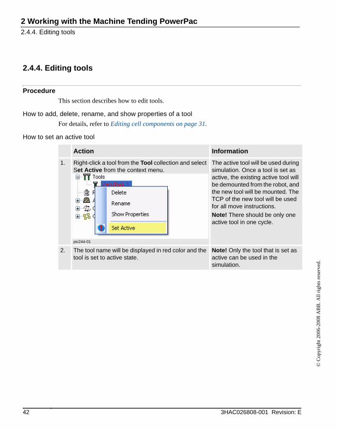
How to set an active tool
Action Information
1. Right-click a tool from the Tool collection and select Set Active from the context menu.
pic244-01
The active tool will be used during simulation. Once a tool is set as active, the existing active tool will be demounted from the robot, and the new tool will be mounted. The TCP of the new tool will be used for all move instructions.Note! There should be only one active tool in one cycle.
2. The tool name will be displayed in red color and the tool is set to active state.
Note! Only the tool that is set as active can be used in the simulation.
42 3HAC026808-001 Revision: E

2 Working with the Machine Tending PowerPac2.4.5. Editing parts
© C
opyr
ight
200
6-20
08 A
BB
. All
right
s res
erve
d.
2.4.5. Editing parts
ProcedureThis section describes how to edit parts.
How to delete, rename, and show properties of a partFor details, refer to Editing cell components on page 31.
How to add a part
Action Information
1. Right-click the Parts collection.
pic245-03
2. Select Add part from library to launch the Create new part dialog box.
• Select a part from the drop-down list under Template in the dialog box.
• If necessary, change the automatically generated name in the text box under Name.
• Click the Add button to add the new part to the 3D cell.
Or select Add part from RS, a part that is imported using RobotStudio basic function will be added to the current cell.
Note! Only when using Add part from RS, the part that is imported using RobotStudio basic function can be used in Machine Tending PowerPac.Refer to Operating manual - RobotStudio for how to import parts with RobotStudio.
Machine Tending PowerPac will place the new parts next to the cell.
433HAC026808-001 Revision: E

2 Working with the Machine Tending PowerPac2.4.6. Editing auxiliary devices
© C
opyr
ight
200
6-20
08 A
BB
. All
right
s res
erve
d.
2.4.6. Editing auxiliary devices
ProcedureThis section describes how to edit auxiliary devices.
How to edit fences
Action Information
1. Right-click the Auxiliary Devices from the Process View:
• select Add a Fence or Robot Base to add a fence element,
• from the Create new Auxiliary Station editing window select Fence.
pic246-04
44 3HAC026808-001 Revision: E
Continues on next page

2 Working with the Machine Tending PowerPac2.4.6. Editing auxiliary devices
© C
opyr
ight
200
6-20
08 A
BB
. All
right
s res
erve
d.
Continued
2. Right-click the Fence:• select Add Fence to add an entire fence
which fits the size of the robot cell,• select Remove Fence to delete all the
fences,• select Modify the Height of All the Fences
and change the value from a pop-up window.
pic246-05
pic246-06
3. It is also possible to edit individual fence element.
pic246-07
See Editing cell components on page 31 for detailed description.
Action Information
453HAC026808-001 Revision: E
Continues on next page
2 Working with the Machine Tending PowerPac2.4.6. Editing auxiliary devices
© C
opyr
ight
200
6-20
08 A
BB
. All
right
s res
erve
d.
Continued
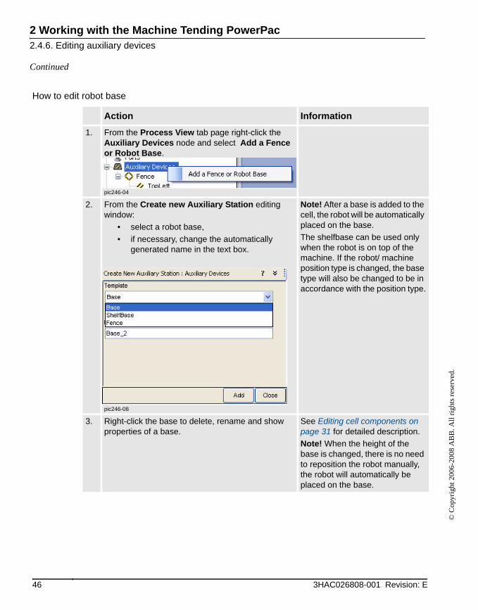
How to edit robot base
Action Information
1. From the Process View tab page right-click the Auxiliary Devices node and select Add a Fence or Robot Base.
pic246-04
2. From the Create new Auxiliary Station editing window:
• select a robot base,• if necessary, change the automatically
generated name in the text box.
pic246-08
Note! After a base is added to the cell, the robot will be automatically placed on the base.The shelfbase can be used only when the robot is on top of the machine. If the robot/ machine position type is changed, the base type will also be changed to be in accordance with the position type.
3. Right-click the base to delete, rename and show properties of a base.
See Editing cell components on page 31 for detailed description.Note! When the height of the base is changed, there is no need to reposition the robot manually, the robot will automatically be placed on the base.
46 3HAC026808-001 Revision: E
2 Working with the Machine Tending PowerPac2.4.7. Defining a cycle
© C
opyr
ight
200
6-20
08 A
BB
. All
right
s res
erve
d.
2.4.7. Defining a cycle
ProcedureA cycle includes a list of stations which defines how a robot sequentially visits these stations. Several cycles can be defined, but only one cycle can be executed during simulation. This one is called the active cycle. Refer to Creating a cell with the Cell Wizard on page 24.
It is possible to edit the current cycle, or add a new cycle from the Process View. The sections below describe how to define cycles from the Process View.
How to add, delete, and rename a cycleFor details, refer to Editing cell components on page 31.
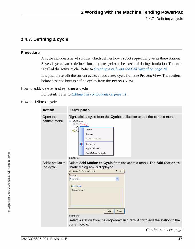
How to define a cycle
Action Description
Open the context menu
Right-click a cycle from the Cycles collection to see the context menu.
pic-245-01
Add a station to the cycle
Select Add Station to Cycle from the context menu. The Add Station to Cycle dialog box is displayed.
pic245-02
Select a station from the drop-down list, click Add to add the station to the current cycle.
473HAC026808-001 Revision: E
Continues on next page
2 Working with the Machine Tending PowerPac2.4.7. Defining a cycle
© C
opyr
ight
200
6-20
08 A
BB
. All
right
s res
erve
d.
Continued
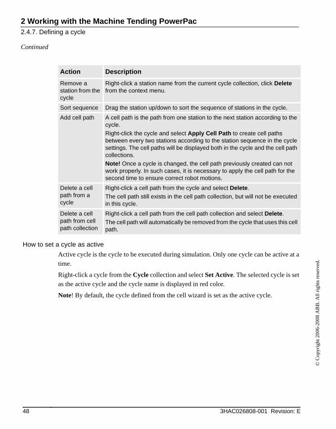
How to set a cycle as activeActive cycle is the cycle to be executed during simulation. Only one cycle can be active at a time.
Right-click a cycle from the Cycle collection and select Set Active. The selected cycle is set as the active cycle and the cycle name is displayed in red color.
Note! By default, the cycle defined from the cell wizard is set as the active cycle.
Remove a station from the cycle
Right-click a station name from the current cycle collection, click Delete from the context menu.
Sort sequence Drag the station up/down to sort the sequence of stations in the cycle.
Add cell path A cell path is the path from one station to the next station according to the cycle.Right-click the cycle and select Apply Cell Path to create cell paths between every two stations according to the station sequence in the cycle settings. The cell paths will be displayed both in the cycle and the cell path collections.Note! Once a cycle is changed, the cell path previously created can not work properly. In such cases, it is necessary to apply the cell path for the second time to ensure correct robot motions.
Delete a cell path from a cycle
Right-click a cell path from the cycle and select Delete.The cell path still exists in the cell path collection, but will not be executed in this cycle.
Delete a cell path from cell path collection
Right-click a cell path from the cell path collection and select Delete.The cell path will automatically be removed from the cycle that uses this cell path.
Action Description
48 3HAC026808-001 Revision: E

2 Working with the Machine Tending PowerPac2.4.8. Auto-placing Cell Components
© C
opyr
ight
200
6-20
08 A
BB
. All
right
s res
erve
d.
2.4.8. Auto-placing Cell Components
Auto-place cell componentsThe Machine Tending PowerPac provides a function called auto-place cell components, which can either position a station, or place all stations, including the machine used in the cell considering collision free environment in the cell and reachability for the robot. This function is available from the Machine Tending PowerPac toolbar collection.
Auto-place one station
Action Information
1. Click Auto-place Cell Components on the Machine Tending PowerPac toolbar.
pic247-03
The Auto-place Cell Components window is displayed.
2. Select a station from the available station list box then click Apply.
If there is a solution, a position for the selected station will be found that can ensure:
• all the targets within the station is reachable for the used robot.
• does not collide other cell components including the robot.
If there is no solution, the station will be placed in a default position that is not in collision with others.
493HAC026808-001 Revision: E
Continues on next page
2 Working with the Machine Tending PowerPac2.4.8. Auto-placing Cell Components
© C
opyr
ight
200
6-20
08 A
BB
. All
right
s res
erve
d.
Continued
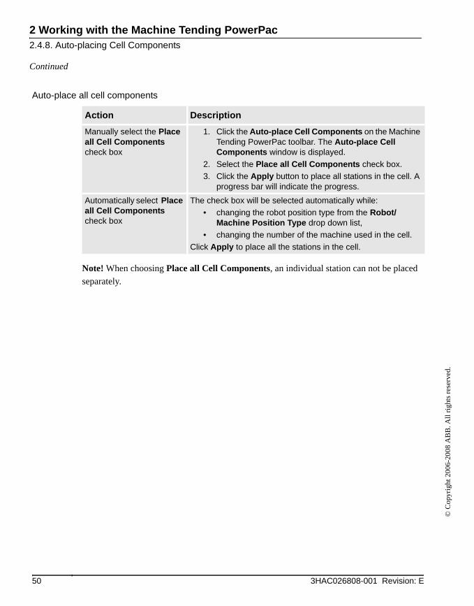
Auto-place all cell components
Note! When choosing Place all Cell Components, an individual station can not be placed separately.
Action Description
Manually select the Place all Cell Components check box
1. Click the Auto-place Cell Components on the Machine Tending PowerPac toolbar. The Auto-place Cell Components window is displayed.
2. Select the Place all Cell Components check box.3. Click the Apply button to place all stations in the cell. A
progress bar will indicate the progress.
Automatically select Place all Cell Components check box
The check box will be selected automatically while:• changing the robot position type from the Robot/
Machine Position Type drop down list,• changing the number of the machine used in the cell.
Click Apply to place all the stations in the cell.
50 3HAC026808-001 Revision: E

2 Working with the Machine Tending PowerPac2.5. Running a Simulation
© C
opyr
ight
200
6-20
08 A
BB
. All
right
s res
erve
d.
2.5. Running a Simulation
Running a simulationSimulates how a robot tends a cell, including states and behaviors of stations. It will:
• Simulates robot motions for the active cycle.
• Simulates different actions of stations within a cycle.
• Simulates interactive logics between the robot and other stations.
For details on editing simulation, refer to Editing stations on page 35.
How to start a simulationClick Play from the simulation toolbar collection to run the simulation.
The graphics window will display how the robot tends the cell.
Note! The Play button will be enabled only after a successful synchronization to the virtual controller.
Refer to Toolbar of Machine Tending PowerPac on page 20 for how to configure the path and synchronize with virtual controller.
How to stop a simulationClick Stop any time the simulation should be stopped.
Note! When the simulation ends, click Jump home to get the robot its original position from current position.
Viewing run time informationDuring simulation, view statistics information from the Statistics tab page. Refer to Statistics Information on page 53.
How to change part handling behaviorIt is possible to customize a tool method action when the simulation is stopped. For example, to set which part will be picked/released for a station, or how long time for a pick/release action. For details, refer to Editing stations on page 35.
How to edit machine simulatorFor a machine, the time for different stages, i.e., time for machine closing, production, opening and allowed time for extraction, can be changed. For details on changing time for machine simulator, refer to Editing stations on page 35.
513HAC026808-001 Revision: E
Continues on next page

2 Working with the Machine Tending PowerPac2.5. Running a Simulation
© C
opyr
ight
200
6-20
08 A
BB
. All
right
s res
erve
d.
Continued
NOTE!When RobotStudio reports "Safety guard stop state" in the Output window, all the tasks related to the virtual controller can’t be implemented. It is recommended that use System Control Panel to solve the "Safety guard stop state" problems. For details, refer to Operating manual - RobotStudio in Dialog boxes on the Controller menu/ The System Control Panel: My System dialog box.
52 3HAC026808-001 Revision: E

2 Working with the Machine Tending PowerPac2.6. Statistics Information
© C
opyr
ight
200
6-20
08 A
BB
. All
right
s res
erve
d.
2.6. Statistics Information
Viewing run time information from Statistics tab pageWhile running a simulation, click the Statistics tab in the Machine Tending tab page collection to view the runtime statistics information:
Note!
• During simulation, statistics information is updated at the end of each cycle.
• Statistics information will be reset when a new cell is created or the simulation is restarted.
pic26-01
533HAC026808-001 Revision: E
Continues on next page

2 Working with the Machine Tending PowerPac2.6. Statistics Information
© C
opyr
ight
200
6-20
08 A
BB
. All
right
s res
erve
d.
Continued
Viewing the information in the analysis windowThe analysis window graphically displays:
• Both machine cycles and robot cycles.
• Nominal machine cycles and simulated machine cycles.
• How a robot cycle fits with the simulated machine cycle,
• The bottlenecks in terms of synchronization of machine and robot.
Item Description
Run Time Information Provides statistics information for:• Cycle time: time for the last cycle.• Number of cycles: how many cycles runs from the
simulation start.• Run time: total simulation time from the simulation start.
Extract Time Provides statistics information for:• Extract Time of each IMM in the cell.
Extract Time is the time from the robot starts going into IMM, until the robot comes out of IMM after necessary processing inside a machine.
Cycle Information Provides statistics information for:• Cycle name: name of the active cycle.• Station list: station name and the execute time for each
station in the active cycle.
Path information Click a station name in station list to show the execute time of each path in the selected station.Meaning of each column:
• Path name.• Execute time for the path in the selected station.• Description.
Reset and Analysis • Click Reset to reset all the statistics information. This can be done only when no simulation is running.
• Click Analysis to display the Analysis window. Refer to Viewing the information in the analysis window on page 54 for more information.
54 3HAC026808-001 Revision: E
Continues on next page
2 Working with the Machine Tending PowerPac2.6. Statistics Information
© C
opyr
ight
200
6-20
08 A
BB
. All
right
s res
erve
d.
Continued
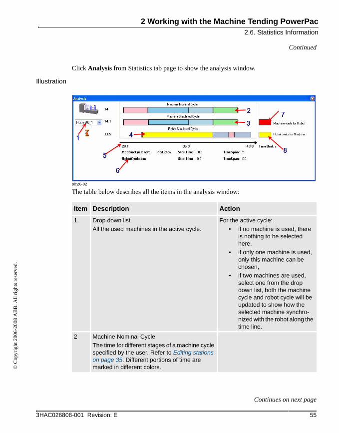
Click Analysis from Statistics tab page to show the analysis window.
Illustration
pic26-02
The table below describes all the items in the analysis window:
Item Description Action
1. Drop down listAll the used machines in the active cycle.
For the active cycle:• if no machine is used, there
is nothing to be selected here,
• if only one machine is used, only this machine can be chosen,
• if two machines are used, select one from the drop down list, both the machine cycle and robot cycle will be updated to show how the selected machine synchro-nized with the robot along the time line.
2 Machine Nominal CycleThe time for different stages of a machine cycle specified by the user. Refer to Editing stations on page 35. Different portions of time are marked in different colors.
553HAC026808-001 Revision: E
Continues on next page
2 Working with the Machine Tending PowerPac2.6. Statistics Information
© C
opyr
ight
200
6-20
08 A
BB
. All
right
s res
erve
d.
Continued
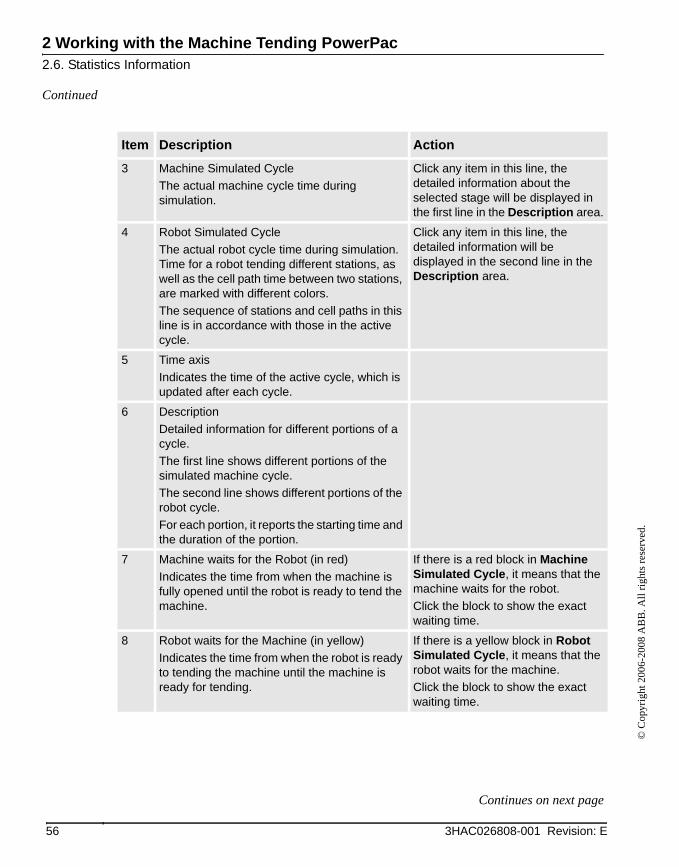
3 Machine Simulated CycleThe actual machine cycle time during simulation.
Click any item in this line, the detailed information about the selected stage will be displayed in the first line in the Description area.
4 Robot Simulated CycleThe actual robot cycle time during simulation. Time for a robot tending different stations, as well as the cell path time between two stations, are marked with different colors.The sequence of stations and cell paths in this line is in accordance with those in the active cycle.
Click any item in this line, the detailed information will be displayed in the second line in the Description area.
5 Time axisIndicates the time of the active cycle, which is updated after each cycle.
6 DescriptionDetailed information for different portions of a cycle.The first line shows different portions of the simulated machine cycle.The second line shows different portions of the robot cycle.For each portion, it reports the starting time and the duration of the portion.
7 Machine waits for the Robot (in red)Indicates the time from when the machine is fully opened until the robot is ready to tend the machine.
If there is a red block in Machine Simulated Cycle, it means that the machine waits for the robot.Click the block to show the exact waiting time.
8 Robot waits for the Machine (in yellow)Indicates the time from when the robot is ready to tending the machine until the machine is ready for tending.
If there is a yellow block in Robot Simulated Cycle, it means that the robot waits for the machine.Click the block to show the exact waiting time.
Item Description Action
56 3HAC026808-001 Revision: E
Continues on next page
2 Working with the Machine Tending PowerPac2.6. Statistics Information
© C
opyr
ight
200
6-20
08 A
BB
. All
right
s res
erve
d.
Continued
NOTE!During simulation, analysis information are updated at the end of each cycle.
NOTE!All the items on the Process view page are unavailable during simulation. To improve the cycle time for machines and robots, stop the simulation first, then do necessary modifications from the Process view. The changes will take effect in the next simulation. Refer to Editing stations on page 35.
573HAC026808-001 Revision: E

2 Working with the Machine Tending PowerPac2.7. Customizing Cell Components
© C
opyr
ight
200
6-20
08 A
BB
. All
right
s res
erve
d.
2.7. Customizing Cell Components
OverviewThe Machine Tending PowerPac provides a library containing several types of stations, one vacuum tool and several kinds of parts that can be used directly.
In case the library does not contain the required station types, tools or parts, it is possible to create new types of station, tool or part by using Customize Cell Components in the Machine Tending PowerPac toolbar collection. The customized items can be saved as a library that a user can use in the coming work.
Note! Once the Customize Cell Components window is launched, the current Machine Tending cell must be cleaned up besides the robot system. It is recommended to save the work before starting to use this function.
pic27-01
58 3HAC026808-001 Revision: E
Continues on next page
2 Working with the Machine Tending PowerPac2.7. Customizing Cell Components
© C
opyr
ight
200
6-20
08 A
BB
. All
right
s res
erve
d.
Continued
ProceduresFollow the procedure below to create a new model:
Item Description
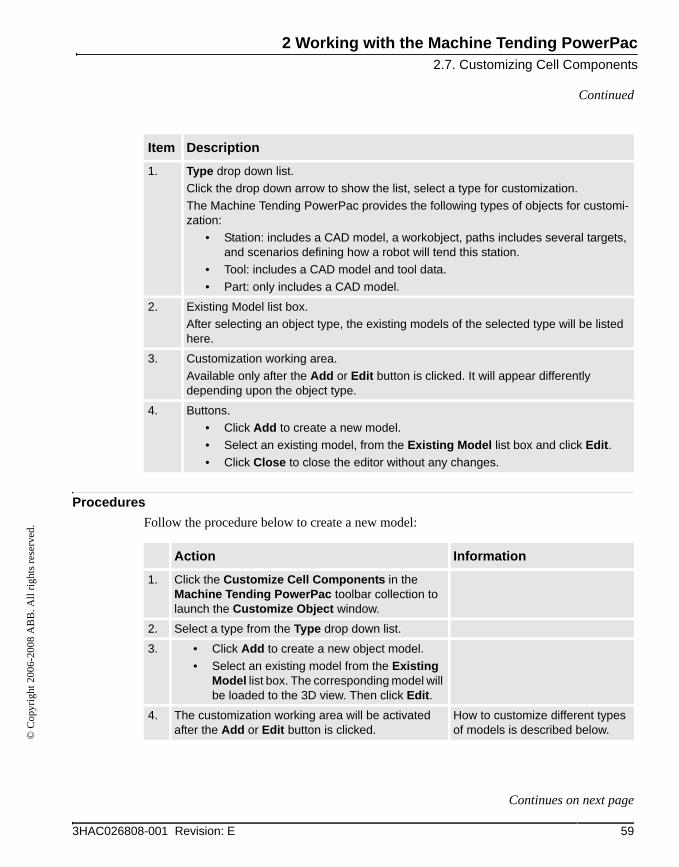
1. Type drop down list.Click the drop down arrow to show the list, select a type for customization.The Machine Tending PowerPac provides the following types of objects for customi-zation:
• Station: includes a CAD model, a workobject, paths includes several targets, and scenarios defining how a robot will tend this station.
• Tool: includes a CAD model and tool data.• Part: only includes a CAD model.
2. Existing Model list box.After selecting an object type, the existing models of the selected type will be listed here.
3. Customization working area.Available only after the Add or Edit button is clicked. It will appear differently depending upon the object type.
4. Buttons.• Click Add to create a new model.• Select an existing model, from the Existing Model list box and click Edit.• Click Close to close the editor without any changes.
Action Information
1. Click the Customize Cell Components in the Machine Tending PowerPac toolbar collection to launch the Customize Object window.
2. Select a type from the Type drop down list.
3. • Click Add to create a new object model.• Select an existing model from the Existing
Model list box. The corresponding model will be loaded to the 3D view. Then click Edit.
4. The customization working area will be activated after the Add or Edit button is clicked.
How to customize different types of models is described below.
593HAC026808-001 Revision: E
Continues on next page
2 Working with the Machine Tending PowerPac2.7. Customizing Cell Components
© C
opyr
ight
200
6-20
08 A
BB
. All
right
s res
erve
d.
Continued
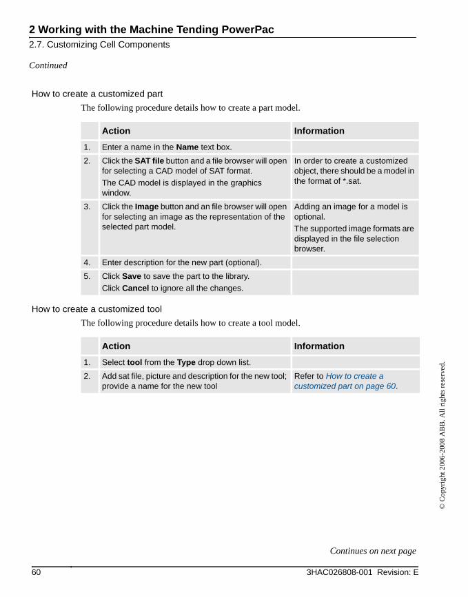
How to create a customized partThe following procedure details how to create a part model.
How to create a customized toolThe following procedure details how to create a tool model.
Action Information
1. Enter a name in the Name text box.
2. Click the SAT file button and a file browser will open for selecting a CAD model of SAT format.The CAD model is displayed in the graphics window.
In order to create a customized object, there should be a model in the format of *.sat.
3. Click the Image button and an file browser will open for selecting an image as the representation of the selected part model.
Adding an image for a model is optional. The supported image formats are displayed in the file selection browser.
4. Enter description for the new part (optional).
5. Click Save to save the part to the library.Click Cancel to ignore all the changes.
Action Information
1. Select tool from the Type drop down list.
2. Add sat file, picture and description for the new tool; provide a name for the new tool
Refer to How to create a customized part on page 60.
60 3HAC026808-001 Revision: E
Continues on next page
2 Working with the Machine Tending PowerPac2.7. Customizing Cell Components
© C
opyr
ight
200
6-20
08 A
BB
. All
right
s res
erve
d.
Continued
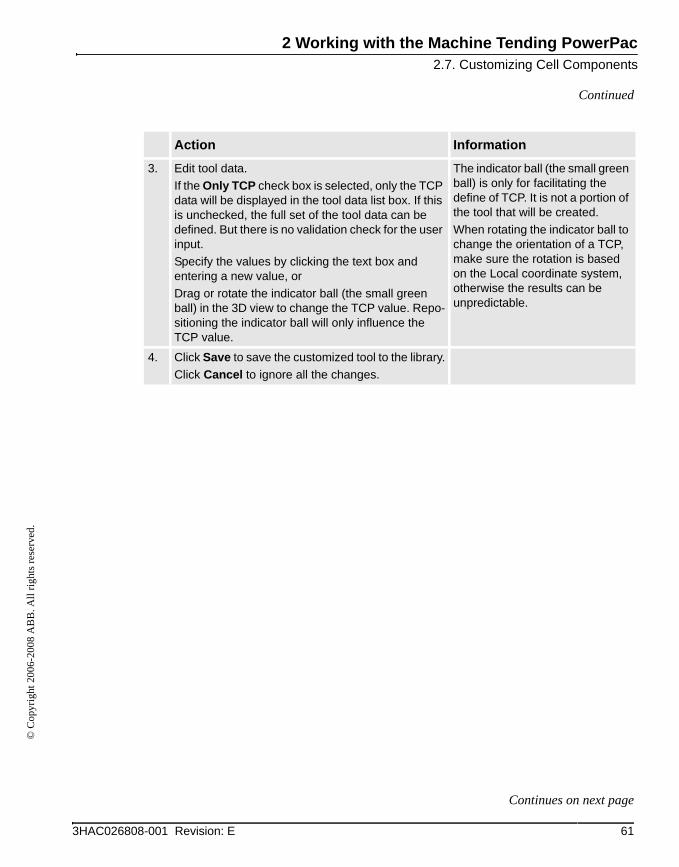
3. Edit tool data.If the Only TCP check box is selected, only the TCP data will be displayed in the tool data list box. If this is unchecked, the full set of the tool data can be defined. But there is no validation check for the user input.Specify the values by clicking the text box and entering a new value, orDrag or rotate the indicator ball (the small green ball) in the 3D view to change the TCP value. Repo-sitioning the indicator ball will only influence the TCP value.
The indicator ball (the small green ball) is only for facilitating the define of TCP. It is not a portion of the tool that will be created.When rotating the indicator ball to change the orientation of a TCP, make sure the rotation is based on the Local coordinate system, otherwise the results can be unpredictable.
4. Click Save to save the customized tool to the library.Click Cancel to ignore all the changes.
Action Information
613HAC026808-001 Revision: E
Continues on next page

2 Working with the Machine Tending PowerPac2.7. Customizing Cell Components
© C
opyr
ight
200
6-20
08 A
BB
. All
right
s res
erve
d.
Continued
How to create a customized stationThe following procedure explains how to create a customized station.
pic27-02
Action Information
1. Select Station from the Type drop down list.
2. Enter a name for the new station. Add SAT file, picture, and provide description for the new station.
Refer to How to create a customized part on page 60.
62 3HAC026808-001 Revision: E
Continues on next page
2 Working with the Machine Tending PowerPac2.7. Customizing Cell Components
© C
opyr
ight
200
6-20
08 A
BB
. All
right
s res
erve
d.
Continued
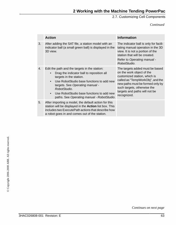
3. After adding the SAT file, a station model with an indicator ball (a small green ball) is displayed in the 3D view.
The indicator ball is only for facili-tating manual operation in the 3D view. It is not a portion of the station that will be created.Refer to Operating manual - RobotStudio.
4. Edit the path and the targets in the station:• Drag the indicator ball to reposition all
targets in the station.• Use RobotStudio base functions to add new
targets. See Operating manual - RobotStudio.
• Use RobotStudio base functions to add new paths. See Operating manual - RobotStudio.
The targets added must be based on the work object of the customized station, which is called as "TempWorkObj", and the new paths must be formed only by such targets, otherwise the targets and paths will not be recognized.
5. After importing a model, the default action for this station will be displayed in the Action list box. This includes two ExecutePath actions that describe how a robot goes in and comes out of the station.
Action Information
633HAC026808-001 Revision: E
Continues on next page
2 Working with the Machine Tending PowerPac2.7. Customizing Cell Components
© C
opyr
ight
200
6-20
08 A
BB
. All
right
s res
erve
d.
Continued
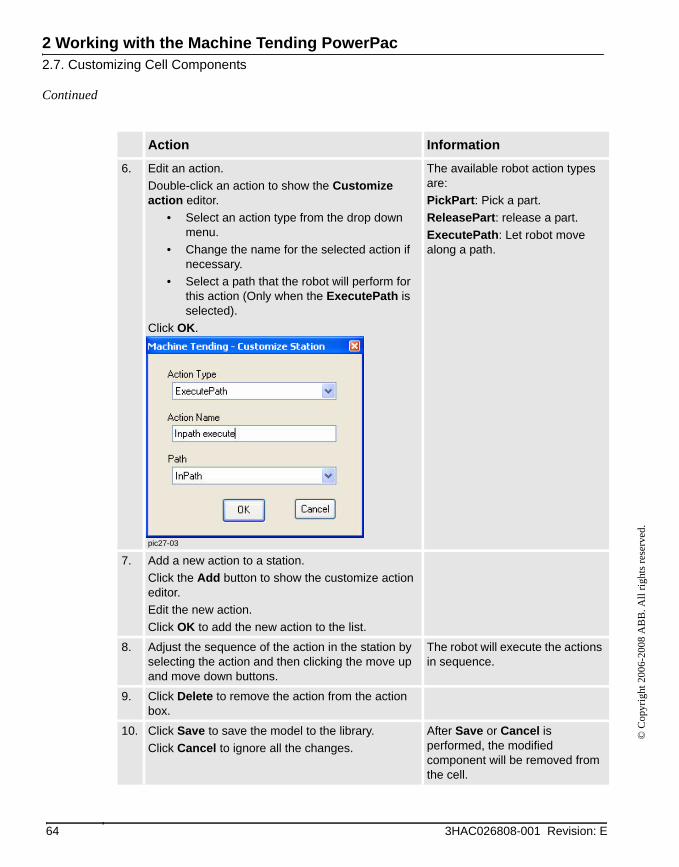
6. Edit an action.Double-click an action to show the Customize action editor.
• Select an action type from the drop down menu.
• Change the name for the selected action if necessary.
• Select a path that the robot will perform for this action (Only when the ExecutePath is selected).
Click OK.
pic27-03
The available robot action types are:PickPart: Pick a part.ReleasePart: release a part.ExecutePath: Let robot move along a path.
7. Add a new action to a station.Click the Add button to show the customize action editor.Edit the new action.Click OK to add the new action to the list.
8. Adjust the sequence of the action in the station by selecting the action and then clicking the move up and move down buttons.
The robot will execute the actions in sequence.
9. Click Delete to remove the action from the action box.
10. Click Save to save the model to the library.Click Cancel to ignore all the changes.
After Save or Cancel is performed, the modified component will be removed from the cell.
Action Information
64 3HAC026808-001 Revision: E
2 Working with the Machine Tending PowerPac2.8. Exporting and Importing Templates
© C
opyr
ight
200
6-20
08 A
BB
. All
right
s res
erve
d.
2.8. Exporting and Importing Templates
OverviewThe Machine Tending PowerPac provides a library containing several types of templates that can be used directly. And it is also possible to share customized stations, tools and parts between different users by exporting and importing templates.
Exporting templatesThe following procedure details how to export templates.
Action Information
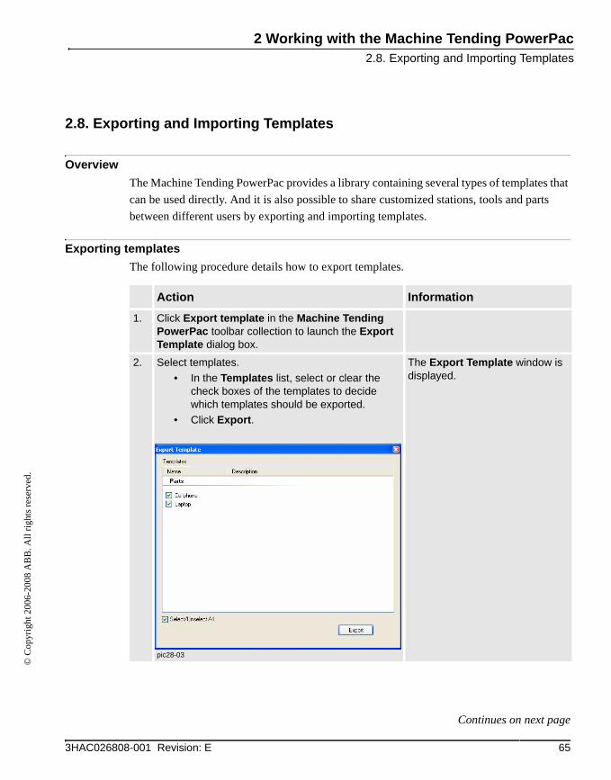
1. Click Export template in the Machine Tending PowerPac toolbar collection to launch the Export Template dialog box.
2. Select templates.• In the Templates list, select or clear the
check boxes of the templates to decide which templates should be exported.
• Click Export.
pic28-03
The Export Template window is displayed.
653HAC026808-001 Revision: E
Continues on next page

2 Working with the Machine Tending PowerPac2.8. Exporting and Importing Templates
© C
opyr
ight
200
6-20
08 A
BB
. All
right
s res
erve
d.
Continued
Importing templates to Machine Tending PowerPacThe following procedure details how to import templates.
3. Save the templates as a cab file.• Specify the location in Save in.• Enter a name for the cab file in the File name
text box.• Click Save.
All the selected templates will be saved in a cab file at the specified location.
Action Information
Action Information
1. Click Import template in the Machine Tending PowerPac toolbar collection to launch the Import Template window.
2. Select a cab file.• In Look in, browse to the location where the
cab have been stored.• Select a desired cab file.• Click the Open button.
The Import Template window is displayed.
Note! Only the cab files that are exported by Machine Tending PowerPac can be imported.
66 3HAC026808-001 Revision: E
Continues on next page

2 Working with the Machine Tending PowerPac2.8. Exporting and Importing Templates
© C
opyr
ight
200
6-20
08 A
BB
. All
right
s res
erve
d.
Continued
3. Select templates.• Select or clear the check boxes of the
templates to decide which templates should be imported to the Machine Tending PowerPac.
• Click the Import button.
pic28-01
All the templates in the cab file will be list in the Import Template window.
Action Information
673HAC026808-001 Revision: E
Continues on next page
2 Working with the Machine Tending PowerPac2.8. Exporting and Importing Templates
© C
opyr
ight
200
6-20
08 A
BB
. All
right
s res
erve
d.
Continued
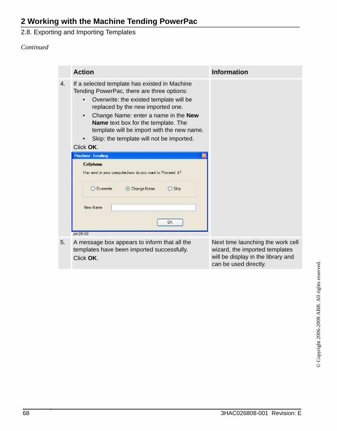
4. If a selected template has existed in Machine Tending PowerPac, there are three options:
• Overwrite: the existed template will be replaced by the new imported one.
• Change Name: enter a name in the New Name text box for the template. The template will be import with the new name.
• Skip: the template will not be imported.Click OK.
pic28-02
5. A message box appears to inform that all the templates have been imported successfully.Click OK.
Next time launching the work cell wizard, the imported templates will be display in the library and can be used directly.
Action Information
68 3HAC026808-001 Revision: E
Index©
Cop
yrig
ht 2
006-
2008
AB
B. A
ll rig
hts r
eser
ved.
AAction
action type 39edit action 37
Analysis window 54Auto-place cell components 49
CCell Wizard
create a cell 24interface 23
Customize cell components 58Cycle 47
MMachine Tending PowerPac
installation 11key features 8launching 15toolbar 20user interface 19
SScenario 36Simulation 51Simulator 41Station
concept 18edit stations 35
Statistics information 53
69

Index
© C
opyr
ight
200
6-20
08 A
BB
. All
right
s res
erve
d.
70


