65
Robust Distributed Embedded Systems - Communication TORBJÖRN WILUND Master of Science Thesis Stockholm, Sweden 2006
Robust Distributed Embedded Systems - Communication
TORBJÖRN WILUND
Master of Science Thesis Stockholm, Sweden 2006

Robust Distributed Embedded Systems - Communication
Torbjörn Wilund
Master of Science Thesis MMK 2006:90 MDA 281 KTH Industrial Engineering and Management
Machine Design SE-100 44 STOCKHOLM

Master of Science Thesis MMK 2006:90 MDA 281
Robust Distributed Embedded Systems - Communication
Torbjörn Wilund
Approved
2006-12-20 Examiner
Martin Törngren Supervisor
Martin Törngren Commissioner
KTH Industrial Engineering and Management
Contact person
Martin Törngren
Abstract This thesis tries in its theoretical part to discuss what the term of robustness means for distributed embedded systems. Development of today generally tries to exchange mechanical and electrical solutions for embedded control systems. There are a lot of benefits to gain by designing in a distributed way, this due to internal independencies between nodes for monitoring and error detection. The outcome about robustness suggests that it depends on integrity to achieve availability and reliability, or loss of alternations of information in the different nodes in the distributed system. Reliability depends on how faults in terms of time and value are treated during execution. All studied network protocols have protection of information by different redundancy algorithms such as CRC, which gives the opportunity for fault and error detection. However there are differences in how time is handled, if there is any time handling, and possibility for time synchronization in the hardware. From this perspective the best alternatives are time triggered architectures of current technology. The experimental part tries to evaluate the GAST delivered platform. The work to achieve communication on TTP/C controllers failed due to shortage in the assembled platform. More specifically this is probably the case of bugs in the design of the physical layer of the GAST hardware (not the TTP controllers themselves). By use of recommended backplane, the sent signals are not appearing as expected, and information sent is misinterpreted by external communication devices. A suggestion and recommendation for future work is analysis of the signal in the data bus, and possible design of a filter if current assembly shall be used. The platform has a future for development and research in the field of distributed embedded systems due to its openness, however there is a lack of drivers for the platform integrated network protocols. This must be attended if the platform shall have any significance. The evaluation of TTP Plan generated code shows, that there are possibilities to extract configuration information form tool for configuration of platform. To achieve this some kind of extraction script must be developed.


Examensarbete MMK 2006:90 MDA 281
Robusta Distribuerade Inbyggda System – Kommunikation
Torbjörn Wilund
Godkänt
2006-12-20
Examinator
Martin Törngren
Handledare
Martin Törngren Uppdragsgivare
KTH Industriell Teknik och Management
Kontaktperson
Martin Törngren
Sammanfattning Detta examensarbete diskuterar i sin teoretiska del vad begreppet robusthet betyder för distribuerade inbyggda system. Utvecklingen går idag generellt emot att byta mekaniska och elektriska lösningar mot mekatroniska styrsystem. Det finns sedan mycket att vinna på att göra dessa inbyggda styrsystem distribuerade, bland annat beroende på oberoende mellan noder för intern övervakning och feldetektering. Delresultatet om robusthet säger att det beror på integritet för att uppnå tillgänglighet och tillförlitlighet, det vill säga att informationen är den samma i alla berörda noder. Tillförlitligheten beror på hur fel i tid och värde hanteras under systemexekvering. Informationen skyddas i samtliga undersökta protokoll genom redundans av diverse algoritmer, exempelvis CRC vilket ger möjlighet till feldetektering. Skillnad finns dock i hur tidssynkronisering hanteras om det ens finns hantering av för detta. Ur detta perspektiv är endast tidsstyrda nätverksprotokoll av nuvarande alternativ mest tekniskt lämpliga. Den praktiska delen försöker utvärdera GAST levererad hårdvara. Arbetet med att få igång någon kommunikation på TTP/C misslyckades, detta beroende på brister i den sammansatta plattformen. Mer specifikt beror detta troligtvis på konstruktionsfel i det fysiska lagret av plattformen. Med valt bakplan blir ej signalerna som förväntat vilket gör att informationen tolkas fel av externa kommunikations kretsar. Därför rekommenderas närmare analys av signalen i databussen och eventuell konstruktion av ett filter till bakplanet om nuvarande hopsättning skall användas. Plattformen har med sin öppenhet en framtid för utveckling och forskning kring distribuerade inbyggda system, dock saknas färdiga drivrutiner för de i plattformen integrerade protokollen. Detta är något som måste åtgärdas ifall plattformen skall få någon form av betydelse innan tekniken är för gammal. Undersökningen av den TTP Plan genererade koden visar att det går att extrahera information från verktyget och på så sätt utnyttja verktyget för konfiguration. För att detta skall fungera bör man tillverka någon form av verktyg för detta.


Preface and Acknowledgements This page is often used to thank people that have influenced the result in some way. Also I would like this opportunity. Persons mentioned in unspecified order of significance. A special thanks to my parents, who have supported me all the way in my endeavor to try to achieve something that can be compared to an approved result. Lori Elvsén for her helps to proofread the language. Last but not least, I would like to thank Dan Öhlund, Nicklas Sundberg and Madelene Ymerson for unnecessary long, but the pleasant company.

Table of Contents 1 Introduction ........................................................................................................................ 1
1.1 Background ................................................................................................................ 1 1.2 Objective .................................................................................................................... 1 1.3 Method ....................................................................................................................... 1 1.4 Related work .............................................................................................................. 2 1.5 Context of thesis......................................................................................................... 2
2 Basics of robustness for embedded systems ...................................................................... 5 2.1 Dependability and concerns ....................................................................................... 5 2.2 Faults and impairments .............................................................................................. 6 2.3 Methods for fault management .................................................................................. 7 2.4 Definition of robustness for distributed embedded systems ...................................... 8
3 Designing safety critical systems ....................................................................................... 9 3.1 Development models.................................................................................................. 9
3.1.1 V-model............................................................................................................ 10 3.2 Design considerations .............................................................................................. 11
3.2.1 Requirements and specification ....................................................................... 11 3.2.2 Errors subjected to embedded systems............................................................. 12 3.2.3 Redundancy...................................................................................................... 13 3.2.4 Distributed vs. Centralized............................................................................... 15 3.2.5 Time-triggered vs. Event-triggered .................................................................. 16 3.2.6 Synchronization................................................................................................ 17
3.3 Design methods and tools ........................................................................................ 18 3.3.1 Software ........................................................................................................... 18 3.3.2 Simulation and co-design ................................................................................. 19
3.4 Design summary....................................................................................................... 20 4 Real-Time communication for automotive embedded systems ....................................... 21
4.1 OSI ........................................................................................................................... 21 4.2 GAST implemented embedded communication ...................................................... 25
4.2.1 CAN ................................................................................................................. 25 4.2.2 TTCAN............................................................................................................. 27 4.2.3 LIN ................................................................................................................... 29 4.2.4 TTP................................................................................................................... 31 4.2.5 Flexray.............................................................................................................. 33 4.2.6 Robustness of the protocols.............................................................................. 35
5 Experimental environment ............................................................................................... 37 5.1 Objective .................................................................................................................. 37 5.2 Assembly of GAST platform and idea of operation ................................................ 37 5.3 Main development environment............................................................................... 40 5.4 TTTech TTP software suit ....................................................................................... 41 5.5 Experimental environment and summary of work................................................... 42 5.6 Summary of experiences from the GAST project.................................................... 43
6 Summary and conclusion ................................................................................................. 45 7 Reference.......................................................................................................................... 47 8 List of figures ................................................................................................................... 51 9 Table of Abbreviations for area ....................................................................................... 53

Robust Distributed Embedded Systems - Communication
1 Introduction This thesis is carried out at the Embedded Control Systems research group, which is a part of the Division of Mechatronics at the Department of Machine Design at the Royal Institute of Technology, Stockholm.
1.1 Background The goal of the Embedded Control Systems research group is to provide methods and techniques for development of future dependable and cost-effective embedded control systems, supported by scientific facts and knowledge. Research focuses on architectural design and interdisciplinary practices as a specialization of mechatronics for the design of mechatronical systems. Work covers both methodology and analytical techniques. Work about methodology mainly covers model based development for improvement of embedded control and embedded software. One challenge of the development of embedded applications is to find suitable and cost-effective hardware. General Application Development Boards for Safety Critical Time-Triggered Systems, “GAST”,is a joint project by the university and the industry. The GAST project is a non profitable project founded by The Swedish Governmental Agency for Innovation Systems (VINNOVA). The goal of the GAST project is to deliver an application board for general research of different embedded systems designs, as well as to develop open source platforms of hardware and software for distributed embedded real-time systems. One specific aim of the GAST project is to deliver communication electronics for future communication protocols in the control-by-wire sector. These communication boards will implement the state of the art protocols; TTCAN, TTP/C and FlexRay. The Embedded Control Systems research group is a participating member of the GAST project.
1.2 Objective To evaluate the delivered platform by assembling GAST delivered equipment, and to focus on the assembly of a communication prototype using TTP/C. The first goal is to make it work and secondly implement and test mechanisms regarding robustness.
1.3 Method A literature study will form the framework for robust and dependable system design to create an understanding when comparing robustness of communication protocols individually and communication robustness in relationship to overall system robustness.
• How does one define robustness of a distributed embedded system? • What affects overall system robustness, what methods are used? • Are there any design considerations regarding robustness; where the robustness is
situated? • How does one evaluate robustness in distributed embedded systems? • How does the robustness definition concern standard communication protocols?
The experimental section focuses on assembling the equipment; evaluating the platform for choice of development environment. Finally try to achieve communication on TTP/C controllers.
1
Introduction
1.4 Related work This master thesis is related to parts of progressing work within the Embedded Control Systems group. Other related theses are:
• Real-Time Communication – Evaluation of Protocols for Automotive Systems by Michael Waern [Waern, 2003].
• Internal Real-Time Communication in future Swedish satellites by Martin Normark [Normark, 2003].
• Development of a Safety Critical Mechatronical System Used as Demonstrator for GAST Project by Dan Cornelesen and Patrik Dahlqvist [Cornelesen, 2004]
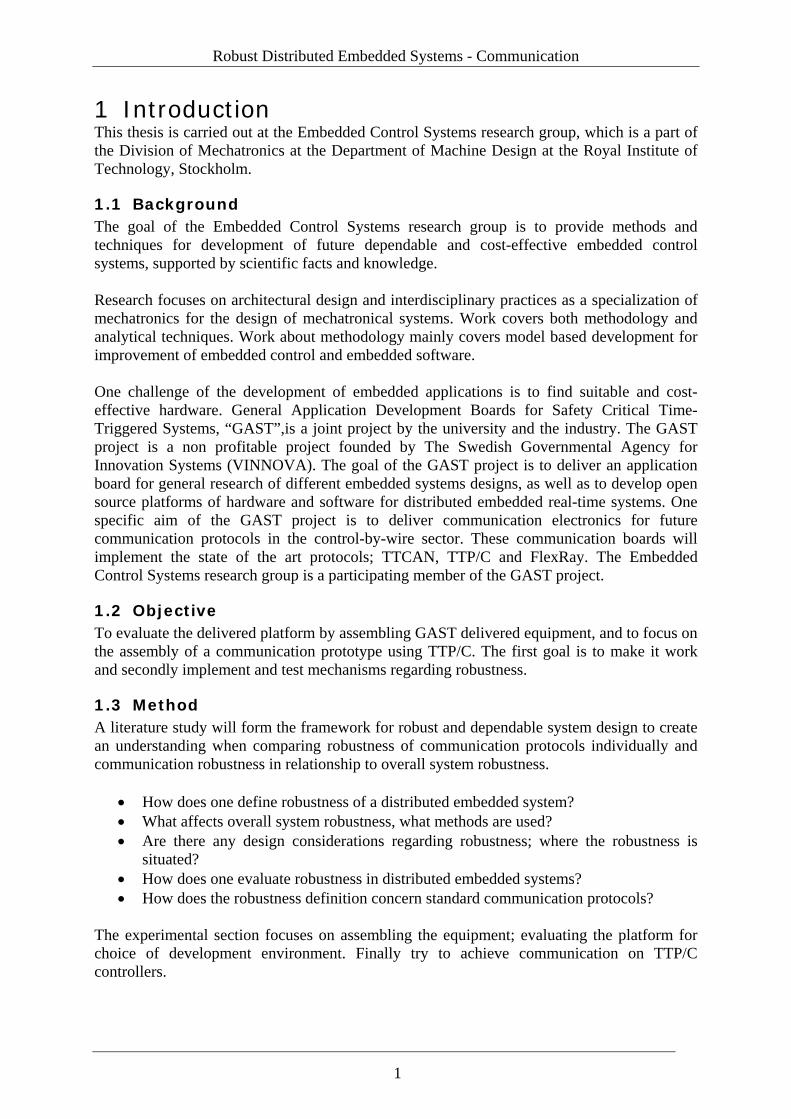
1.5 Context of thesis Mechatronics is the interdisciplinary engineering field that involves mechanical design, electronics and computing. The purpose of this field is the design of automata, to control advanced hybrid-systems. An automaton (plural: automata) is a self-operating machine. The word is sometimes used to describe an autonomous robot. A typical mechatronical design could involve machine components, sensor elements, electronic circuits, communications links, control theory, digital signal processing and software. The term "mechatronics" was first introduced by Mr. Tetsuro Mori, a Japanese senior engineer in 1969 [Wikipedia, 2005a].
Figure 1: Area of mechatronics
An embedded system is defined as computing power which cannot be seen from outside as a separate traditional computer [NatEnc, 2005]. From this definition it seems that an Electronical Control Unit (ECU) formed only by the processor and software running is the system. However an embedded system is often defined as a special purpose computerized subsystem, designed and encapsulated by the device it operates in. Apollo Guidance Computer was the first recognizably modern embedded system, developed by Charles Stark Draper at the MIT Instrumentation Laboratory [Wikipedia, 2005b]. Embedded systems can be found in almost all everyday equipment, and the list is endless where humans receive their services. Examples can be found in mobile phones, airplanes, microwave ovens, wristwatches, television sets and measurement equipment. Examples from automotive solutions are of great interest, due to the vast numbers of units produced, the automotive system complexity and the industries economical sensitivity. Automotive embedded system designs of today have emerged and are attempting to address
2
Robust Distributed Embedded Systems - Communication
solutions from different areas of engineering, both the electrical and the mechanical field. This is being done in order to save money, weight and add flexibility due to the nature of software. Today’s automotive embedded solutions also try to provide services that help the driver to convey the vehicle safer and easier, along with entertainment. Embedded systems that perform some kind of control task are classified as embedded control systems. System boundaries for embedded control systems are defined from sensor to actuator. These systems are often called embedded real-time systems because they are regulating a real-time application or process. In the 1980’s and 1990’s automotive systems replaced solutions where mechanical designs and/or analogue control have had exclusive rights - functions similar to ABS, dashboard information display and engine control. These functions were stand alone embedded systems depending only on their own sets of sensors and/or actuators. The introduction of Controller Area Network (CAN) enabled a simple method of information exchange. With the use of signal sharing, the automotive industry saves money due to use of less cabling and fewer costive sensors. This together introduced distributed embedded control in vehicles. A distributed embedded control system is a system that is spread over many ECUs where sensors are connected to one processor and the actuators and regulator software might be based on another processor. The information exchange between the processors is done by communication link; often a communication bus e.g. CAN. An ECU connected to the link is called a node. A standardized and/or defined communication interface is called communication protocol. Earlier distributed embedded control might have been safety related. We are now on the doorstep of replacing safety critical mechanical solutions like steering and braking. This introduces x-by-wire technologies, where x could be steer, brake and so on. Distributed services like Skid Traction Control (STC) and Adaptive Cruse Control (ACC) along with the x-by-wire are setting new requirements on communication. These embedded control systems are regulating some physical phenomena which make them safety critical since there is a possibility of consequences on the environment in case of failure. In order to safely implement digital control with closed loop feedback from sensors there is a need for deterministic behavior of the system. High network utilization along with loss of communication determinism speaks for event triggered busses to be replaced with time triggered. Solutions from the avionics industry, where x-by-wire designs have been operating for the last decade, are too expensive. This has created a need for cheaper designs without negotiating on overall safety. The automotive industries larger production quantities should generate lower prices compared to the avionics industry. When automotive design solutions are becoming sufficiently robust, it will be likely to see some kind of spin-off back into the avionics industry. This has already happened with TTP, [Rushby, 2002]
3

Robust Distributed Embedded Systems - Communication
2 Basics of robustness for embedded systems The purpose of this chapter is to provide an introduction to the terminology concerning robustness in order to form and help clarify a context for this thesis.
2.1 Dependability and concerns A set of definitions was developed by Laprie 1992 and slightly rephrased by Storey in 1996. These definitions have been widely accepted for work around dependability [Larses, 2005]. These definitions are used to name and define a set of views that enable one to look upon failsafe operation of a system in a standardized manner. This terminology is suitable for dependability analyses for entire systems down to individual components. The dependability-set of six attributes are all related to each other in various ways. Each attribute is defined below, followed by an explanation of how it is related to embedded systems. Safety is the non-occurrence of catastrophic consequences on the environment [Laprie, 1992]. This concerns the operation of the embedded system and the consequences on the environment in case of a system failure. Safety has been redefined in later work where it is subdivided into internal and external safety [Larses, 2005]. Internal safety is the impact of a component on the system whereas external safety relates to the systems’ impact on the environment in case of failure. Attribute requirement on system: Minimize impact of consequences in case of failure. Reliability is the probability of a component or system functioning correctly over a given period of time and under a given set of operating conditions [Storey, 1996]. This can be calculated mathematically as e.g. MTTF – Mean Time To Failure. In relation to embedded computing and runtime this is where the error correcting mechanisms are located in order to improve e.g. MTTF. Attribute requirement on system: Accurate service. Availability of a system is the probability that the system will be functioning correctly at any given time [Storey, 1996]. High availability is often a design goal. For many systems it represents high ‘uptime’, which is particularly evident in banking and ATM systems. Embedded system operating as defined and deriving results (without regarding correctness) is availability. Attribute requirement on system: Readiness for service. Confidentiality is the non-occurrence of unauthorized disclosure of information [Laprie, 1992]. Example: applications which rely on public communication to complete tasks, such as the internet or radio, might require encrypting if information is sensitive. Attribute requirement on system: Privacy of information. Integrity is achieved through the non-occurrence of improper alterations of information [Laprie, 1992]. This attribute applies first and foremost to a distributed embedded system. If several nodes rely on the same sensor information to complete their tasks, overall system performance may depend on these nodes receiving the same information at any given time. Attribute requirement on system: Synchronization strategy
5
Basics of robustness for embedded systems
Maintainability is the systems aptitude to undergo repairs and evolutions [Laprie, 1992] A maintainable system should be easy to repair, especially when it comes to exchanging components as a patch-up or upgrade. In some ways one can say that monitoring is a property of maintainability. Attribute requirement on system: Documentation and easy access to hardware and software.
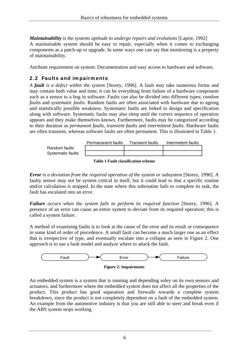
2.2 Faults and impairments A fault is a defect within the system [Storey, 1996]. A fault may take numerous forms and may contain both value and time; it can be everything from failure of a hardware component such as a sensor to a bug in software. Faults can also be divided into different types; random faults and systematic faults. Random faults are often associated with hardware due to ageing and statistically possible weakness. Systematic faults are linked to design and specification along with software. Systematic faults may also sleep until the correct sequence of operation appears and they make themselves known. Furthermore, faults may be categorized according to their duration as permanent faults, transient faults and intermittent faults. Hardware faults are often transient, whereas software faults are often permanent. This is illustrated in Table 1.
Permananent faults Transient faults Intermetent faultsRandom faultsSystematic faults
Table 1 Fault classification scheme
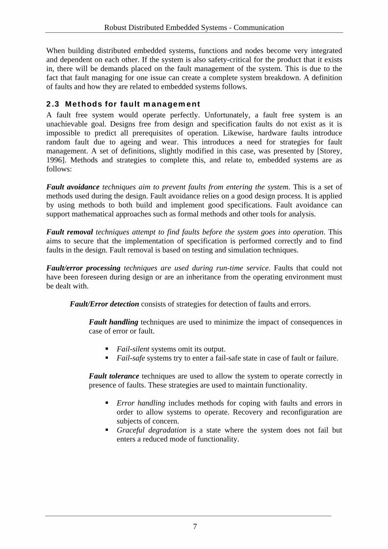
Error is a deviation from the required operation of the system or subsystem [Storey, 1996]. A faulty sensor may not be system critical in itself, but it could lead to that a specific routine and/or calculation is stopped. In the state where this subroutine fails to complete its task, the fault has escalated into an error. Failure occurs when the system fails to perform its required function [Storey, 1996]. A presence of an error can cause an entire system to deviate from its required operation; this is called a system failure. A method of examining faults is to look at the cause of the error and its result or consequence in some kind of order of precedence. A small fault can become a much larger one as an effect that is irrespective of type, and eventually escalate into a collapse as seen in Figure 2. One approach is to use a fault model and analyze where to attack the fault.
Fault Error Failure Figure 2: Impairments
An embedded system is a system that is running and depending soley on its own sensors and actuators, and furthermore where the embedded system does not affect all the properties of the product. This product has good separation and firewalls towards a complete system breakdown, since the product is not completely dependent on a fault of the embedded system. An example from the automotive industry is that you are still able to steer and break even if the ABS system stops working.
6
Robust Distributed Embedded Systems - Communication
When building distributed embedded systems, functions and nodes become very integrated and dependent on each other. If the system is also safety-critical for the product that it exists in, there will be demands placed on the fault management of the system. This is due to the fact that fault managing for one issue can create a complete system breakdown. A definition of faults and how they are related to embedded systems follows.
2.3 Methods for fault management A fault free system would operate perfectly. Unfortunately, a fault free system is an unachievable goal. Designs free from design and specification faults do not exist as it is impossible to predict all prerequisites of operation. Likewise, hardware faults introduce random fault due to ageing and wear. This introduces a need for strategies for fault management. A set of definitions, slightly modified in this case, was presented by [Storey, 1996]. Methods and strategies to complete this, and relate to, embedded systems are as follows: Fault avoidance techniques aim to prevent faults from entering the system. This is a set of methods used during the design. Fault avoidance relies on a good design process. It is applied by using methods to both build and implement good specifications. Fault avoidance can support mathematical approaches such as formal methods and other tools for analysis. Fault removal techniques attempt to find faults before the system goes into operation. This aims to secure that the implementation of specification is performed correctly and to find faults in the design. Fault removal is based on testing and simulation techniques. Fault/error processing techniques are used during run-time service. Faults that could not have been foreseen during design or are an inheritance from the operating environment must be dealt with. Fault/Error detection consists of strategies for detection of faults and errors.
Fault handling techniques are used to minimize the impact of consequences in case of error or fault.
Fail-silent systems omit its output. Fail-safe systems try to enter a fail-safe state in case of fault or failure.
Fault tolerance techniques are used to allow the system to operate correctly in presence of faults. These strategies are used to maintain functionality.
Error handling includes methods for coping with faults and errors in order to allow systems to operate. Recovery and reconfiguration are subjects of concern.
Graceful degradation is a state where the system does not fail but enters a reduced mode of functionality.
7
Basics of robustness for embedded systems
2.4 Definition of robustness for distributed embedded systems Robustness is, in computing terms, its reliability or availability seven days a week, twenty-four hours a day [Wikipedia, 2005c]. This definition combines the terms of availability and reliability during runtime. However, information and data are distributed over a number of nodes in distributed systems. This incorporates the term of integrity in order to achieve reliability. Attribute requirement on system: Durability to distortions so operation and quality of results over time.
Impairments
Concerns
Availability
Reliability
Safety
Confidentiality
Integrity
Maintainability
Fault
Error
Failure
Methods
Fault avoidence
Fault removal
Fault /error processing
Fault/error detection
Fault handling
Fault /error tolerance
Dependability
Robustness
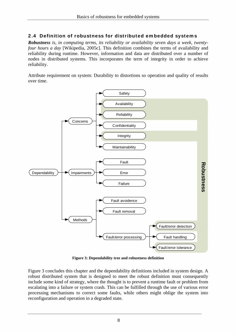
Figure 3: Dependability tree and robustness definition
Figure 3 concludes this chapter and the dependability definitions included in system design. A robust distributed system that is designed to meet the robust definition must consequently include some kind of strategy, where the thought is to prevent a runtime fault or problem from escalating into a failure or system crash. This can be fulfilled through the use of various error processing mechanisms to correct some faults, while others might oblige the system into reconfiguration and operation in a degraded state.
8
Robust Distributed Embedded Systems - Communication
3 Designing safety critical systems Embedded development involves constructing and evolving complex systems, where many people are involved and complete development includes a diverse set of tools and methods. This chapter is written in order to provide some basic knowledge of the design concepts and considerations used in safety critical and robust embedded design.
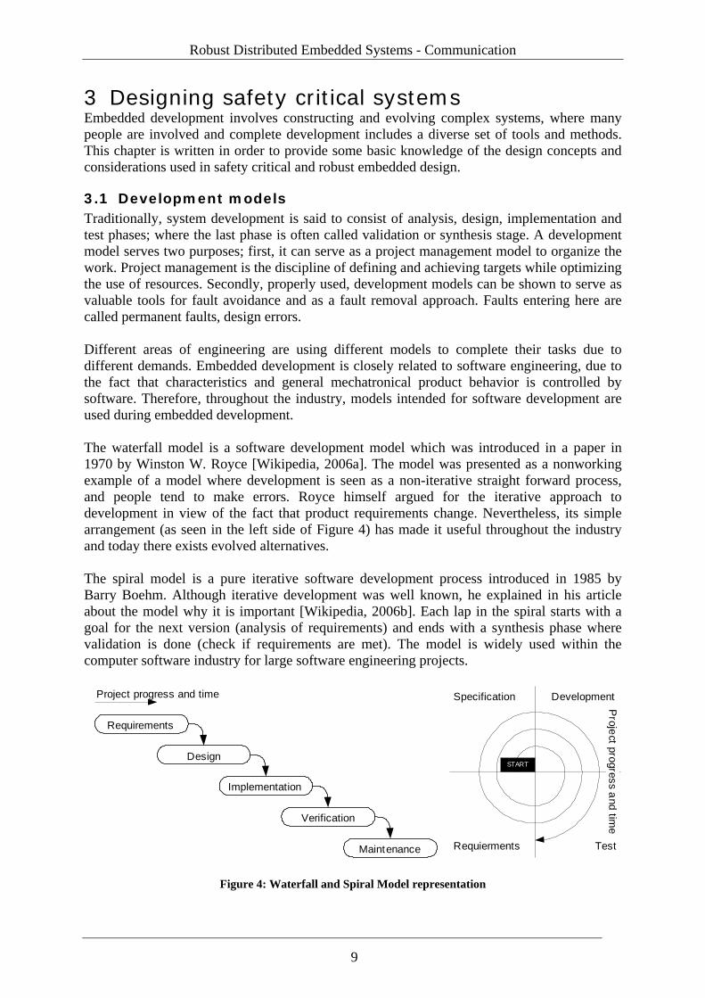
3.1 Development models Traditionally, system development is said to consist of analysis, design, implementation and test phases; where the last phase is often called validation or synthesis stage. A development model serves two purposes; first, it can serve as a project management model to organize the work. Project management is the discipline of defining and achieving targets while optimizing the use of resources. Secondly, properly used, development models can be shown to serve as valuable tools for fault avoidance and as a fault removal approach. Faults entering here are called permanent faults, design errors. Different areas of engineering are using different models to complete their tasks due to different demands. Embedded development is closely related to software engineering, due to the fact that characteristics and general mechatronical product behavior is controlled by software. Therefore, throughout the industry, models intended for software development are used during embedded development. The waterfall model is a software development model which was introduced in a paper in 1970 by Winston W. Royce [Wikipedia, 2006a]. The model was presented as a nonworking example of a model where development is seen as a non-iterative straight forward process, and people tend to make errors. Royce himself argued for the iterative approach to development in view of the fact that product requirements change. Nevertheless, its simple arrangement (as seen in the left side of Figure 4) has made it useful throughout the industry and today there exists evolved alternatives. The spiral model is a pure iterative software development process introduced in 1985 by Barry Boehm. Although iterative development was well known, he explained in his article about the model why it is important [Wikipedia, 2006b]. Each lap in the spiral starts with a goal for the next version (analysis of requirements) and ends with a synthesis phase where validation is done (check if requirements are met). The model is widely used within the computer software industry for large software engineering projects.
Requirements
Design
Implementation
Verification
Maintenance
START
Specification Development
TestRequierments
Project progress and time
Project progress and tim
e
Figure 4: Waterfall and Spiral Model representation
9
Designing safety critical systems
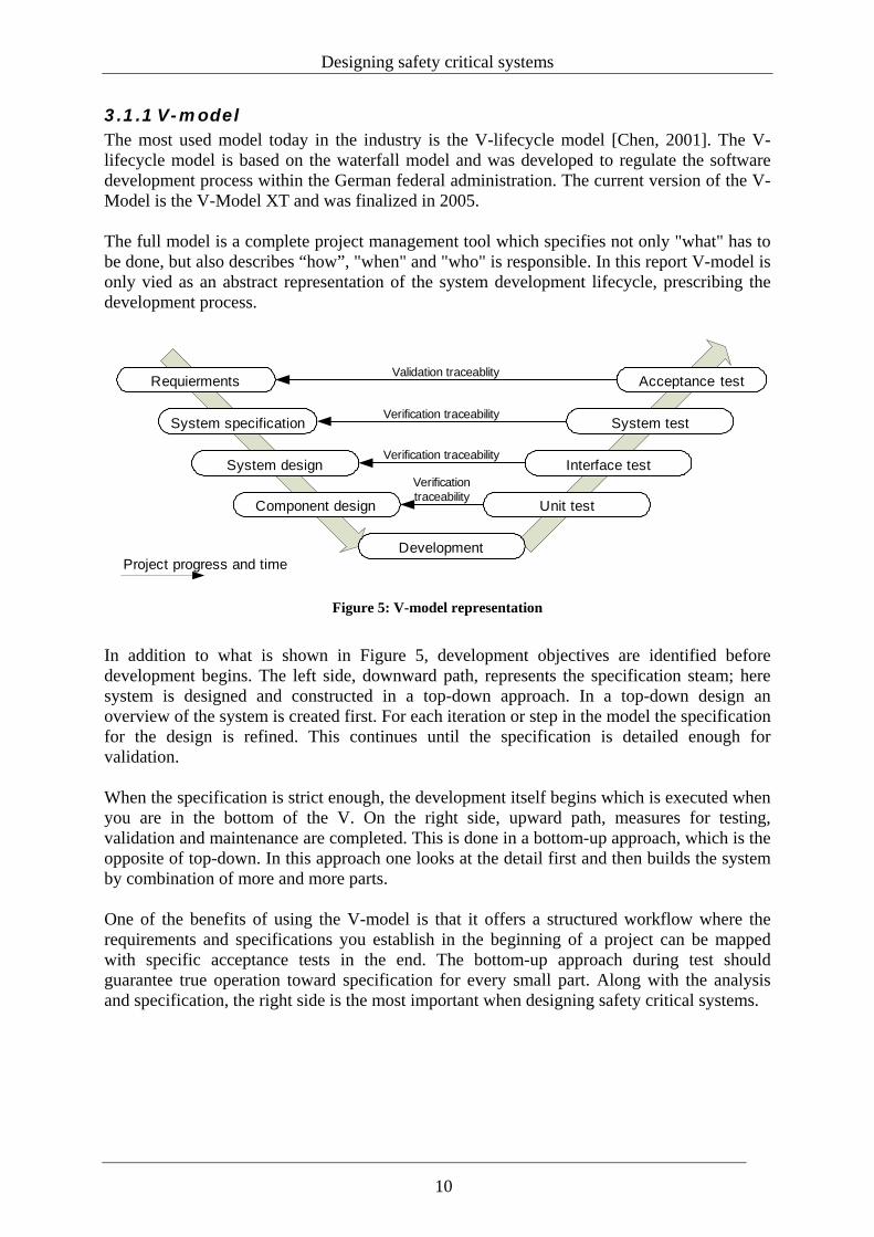
3.1.1 V-model The most used model today in the industry is the V-lifecycle model [Chen, 2001]. The V-lifecycle model is based on the waterfall model and was developed to regulate the software development process within the German federal administration. The current version of the V-Model is the V-Model XT and was finalized in 2005. The full model is a complete project management tool which specifies not only "what" has to be done, but also describes “how”, "when" and "who" is responsible. In this report V-model is only vied as an abstract representation of the system development lifecycle, prescribing the development process.
Development
Requierments
System specification
System design
Component design Unit test
Interface test
System test
Acceptance test
Verification traceability
Verification traceability
Verification traceability
Validation traceablity
Project progress and time
Figure 5: V-model representation
In addition to what is shown in Figure 5, development objectives are identified before development begins. The left side, downward path, represents the specification steam; here system is designed and constructed in a top-down approach. In a top-down design an overview of the system is created first. For each iteration or step in the model the specification for the design is refined. This continues until the specification is detailed enough for validation. When the specification is strict enough, the development itself begins which is executed when you are in the bottom of the V. On the right side, upward path, measures for testing, validation and maintenance are completed. This is done in a bottom-up approach, which is the opposite of top-down. In this approach one looks at the detail first and then builds the system by combination of more and more parts. One of the benefits of using the V-model is that it offers a structured workflow where the requirements and specifications you establish in the beginning of a project can be mapped with specific acceptance tests in the end. The bottom-up approach during test should guarantee true operation toward specification for every small part. Along with the analysis and specification, the right side is the most important when designing safety critical systems.
10
Robust Distributed Embedded Systems - Communication
3.2 Design considerations This section is written in order to acquire knowledge about the basic design considerations and tradeoffs offered to the embedded designer. Fault tolerance is related to architectural design which among other things includes the several ingredients which follow below.
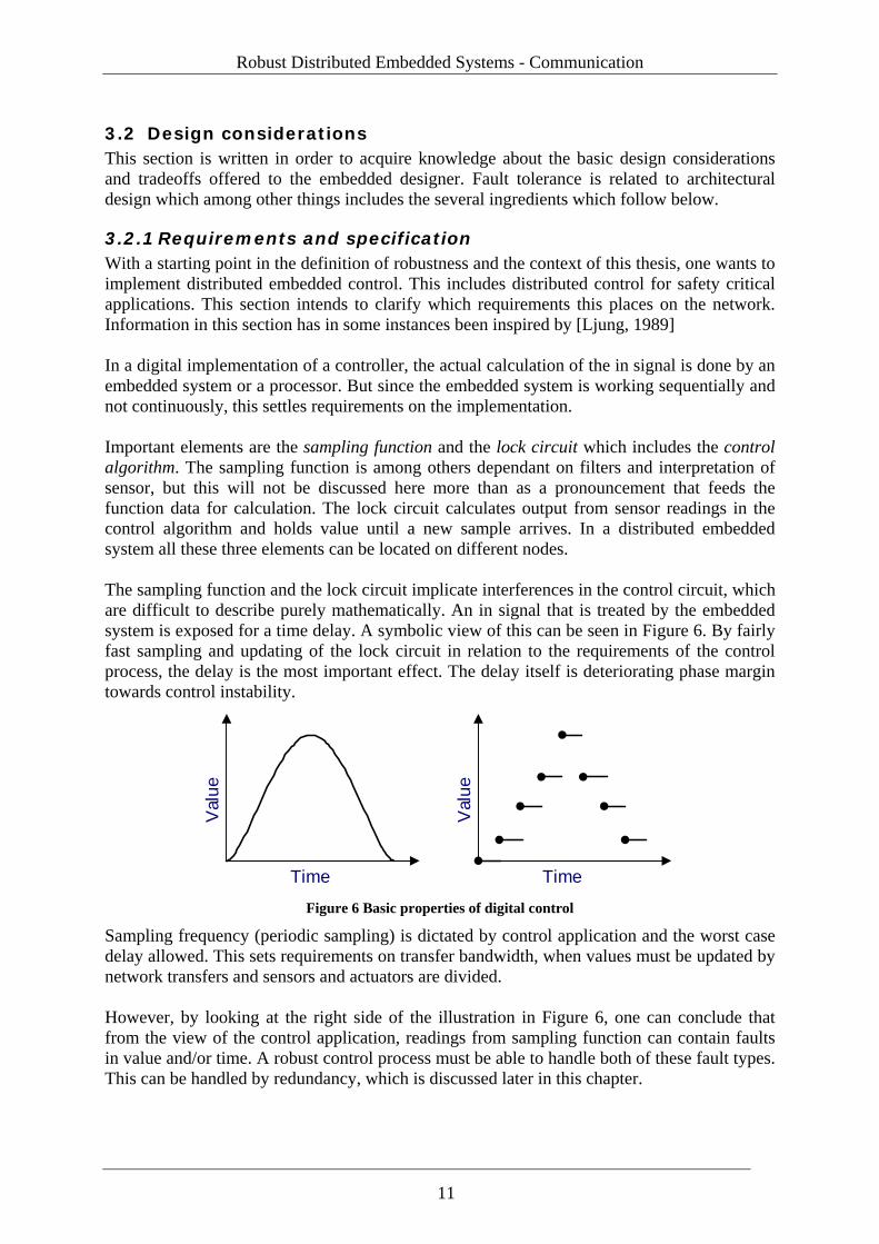
3.2.1 Requirements and specification With a starting point in the definition of robustness and the context of this thesis, one wants to implement distributed embedded control. This includes distributed control for safety critical applications. This section intends to clarify which requirements this places on the network. Information in this section has in some instances been inspired by [Ljung, 1989] In a digital implementation of a controller, the actual calculation of the in signal is done by an embedded system or a processor. But since the embedded system is working sequentially and not continuously, this settles requirements on the implementation. Important elements are the sampling function and the lock circuit which includes the control algorithm. The sampling function is among others dependant on filters and interpretation of sensor, but this will not be discussed here more than as a pronouncement that feeds the function data for calculation. The lock circuit calculates output from sensor readings in the control algorithm and holds value until a new sample arrives. In a distributed embedded system all these three elements can be located on different nodes. The sampling function and the lock circuit implicate interferences in the control circuit, which are difficult to describe purely mathematically. An in signal that is treated by the embedded system is exposed for a time delay. A symbolic view of this can be seen in Figure 6. By fairly fast sampling and updating of the lock circuit in relation to the requirements of the control process, the delay is the most important effect. The delay itself is deteriorating phase margin towards control instability.
Time
Val
ue
Time
Val
ue
Figure 6 Basic properties of digital control
Sampling frequency (periodic sampling) is dictated by control application and the worst case delay allowed. This sets requirements on transfer bandwidth, when values must be updated by network transfers and sensors and actuators are divided. However, by looking at the right side of the illustration in Figure 6, one can conclude that from the view of the control application, readings from sampling function can contain faults in value and/or time. A robust control process must be able to handle both of these fault types. This can be handled by redundancy, which is discussed later in this chapter.
11
Designing safety critical systems
With a starting point in that sensor readings from the sampling function are correct, what requirements are placed on the network since the elements of the control application is separated. By first discussing value faults, data must be protected during transport in order for the lock circuit to be able to trust the information. The second part concerns timing or time. As a result of the separation there is an unknown rate of independency between execution speeds in the different nodes, which implies that the network contributes with some kind of time or timing solution. By periodic execution of the complete controller the age of the data is known. Strict periodicity is by no means mandatory, but the limiting factor is that the data is not too old from the delay point of view. As long as all involved nodes have the same time base, there is a possibility to reverse engineer and analyze how old a time stamped data value is, and then decide if the data is usable. Consequently, the requirement of the network is to provide a distributed clock to elicit time and not to provide timing in the distributed system.
3.2.2 Errors subjected to embedded systems Some basic knowledge about what kind of errors as a deviation from faults an embedded system or distributed relative is subjected to is needed. This subsection attempts to summarize some common errors and is influenced from [Palbus, 2001a] Configuration errors can be derived from mainly two origins. The first type of error is related to poor specifications and bad documentation. The other major type is related to replacement of faulty components where the substitution part is not purely identical to the original component. Node errors or solo system errors can depend on both hardware and software malfunction. Hardware related errors are closely associated to random scarcity in hardware found as mechanical or electrical shortage. These errors are transient or intermittent to its existence. Other hardware related errors are design related errors and they are permanent. Software errors are always permanent due to the nature of software. Errors can derive from specification faults, coding faults, and logical errors but faults can also be induced from a compiler. Communication errors are of great importance in a distributed system. The cause of errors produced on a communication bus can be numerous. An error can be depending on hardware, software or be signal related. Faulty software or hardware can misinterpret signals or occupy the bus by sending information continuously or at the wrong point in time. This specific error is called a babbling idiot. Signal related errors are often related to broken paths, EMI or any other transient cause of event. All types of communication errors can lead to loss or corruption of information. Timing errors are of large concern in embedded control systems. The age of data is important as well as periodic update of information. Faulty timing can be caused by numerous factors. Broken hardware or a failing software process which might suspend the system is a common problem. The result is no or bad control. Data consistency errors are a type of error where the same data is stored in many places, internally or at different nodes in a distributed system. The problem is to determine which
12
Robust Distributed Embedded Systems - Communication
data that is correct and synchronize information among the dependent processes. These errors are often referred to as byzantine errors. Initialization and restart errors are errors that occur during start-up or system resynchronization. Generally it is impossible to know in which order nodes start in a distributed system. This error type prohibits the system to start correctly, achieve synchronization and progress with operation.
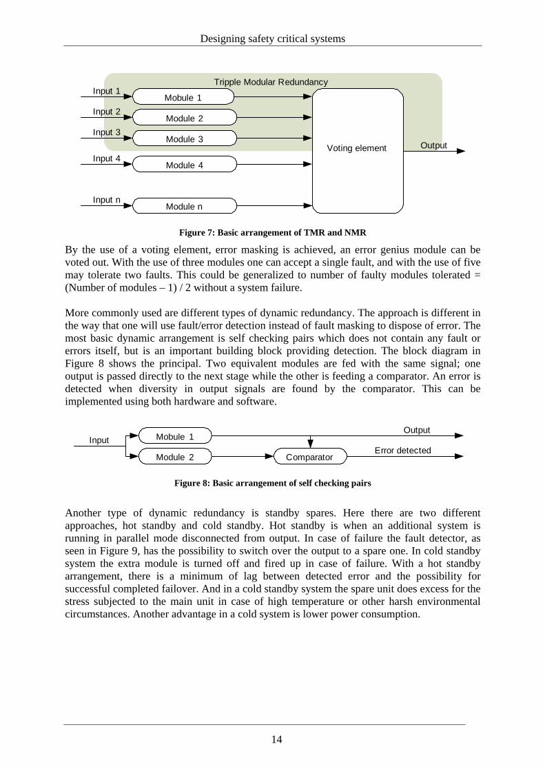
3.2.3 Redundancy No system is fault free and in addition to design integrated faults, transient faults exist depending on the environment the system is working in. That leaves us a need for fault/error processing during run-time service to allow the system to operate correctly. All these error processing techniques are based on some kind of redundancy; comparison renders the possibility to detect errors and multiple sources provides the opportunity to continue operation in case of failure of one. Redundancy is defined in the following ways. This subsection is inspired by [Storey, 1996] Hardware redundancy is the use of hardware in addition to which would be needed to implement system in the absence of faults. This means that one will use additional hardware, similar or duplicate, to be able to detect and tolerate faults. Software redundancy is the use of software in addition to which would be needed to implement system in the absence of faults. This means that one will use additional software, similar or duplicate. This software is running on the same node, identical hardware or another node with the same or different hardware to be able detect and tolerate faults. Information redundancy is the use of information in addition to which would be needed to implement system in the absence of faults. By storing information at different places internally or at different nodes. This also includes the use of party bits, checksums. Temporal redundancy is the use of time in addition to that required to implement a given function. This might be doing a calculation twice separated by time and then compare results. This can be used to detect transient faults. The basic theories for accomplishing redundancy are done by real simple arrangements. Triple Modular Redundancy - TMR is the most basic arrangement of static redundancy and it can easily be expanded into N-Modular Redundancy – NMR as seen in Figure 7. A module can be a piece of software, hardware component or storage space for information.
13
Designing safety critical systems
Tripple Modular Redundancy
Mobule 1
Module 2
Module 3
Module 4
Module n
Voting element Output
Input n
Input 4
Input 3
Input 2
Input 1
Figure 7: Basic arrangement of TMR and NMR
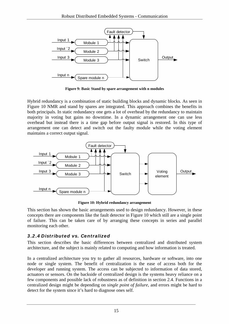
By the use of a voting element, error masking is achieved, an error genius module can be voted out. With the use of three modules one can accept a single fault, and with the use of five may tolerate two faults. This could be generalized to number of faulty modules tolerated = (Number of modules – 1) / 2 without a system failure. More commonly used are different types of dynamic redundancy. The approach is different in the way that one will use fault/error detection instead of fault masking to dispose of error. The most basic dynamic arrangement is self checking pairs which does not contain any fault or errors itself, but is an important building block providing detection. The block diagram in Figure 8 shows the principal. Two equivalent modules are fed with the same signal; one output is passed directly to the next stage while the other is feeding a comparator. An error is detected when diversity in output signals are found by the comparator. This can be implemented using both hardware and software.
Mobule 1
Module 2
InputOutput
ComparatorError detected
Figure 8: Basic arrangement of self checking pairs
Another type of dynamic redundancy is standby spares. Here there are two different approaches, hot standby and cold standby. Hot standby is when an additional system is running in parallel mode disconnected from output. In case of failure the fault detector, as seen in Figure 9, has the possibility to switch over the output to a spare one. In cold standby system the extra module is turned off and fired up in case of failure. With a hot standby arrangement, there is a minimum of lag between detected error and the possibility for successful completed failover. And in a cold standby system the spare unit does excess for the stress subjected to the main unit in case of high temperature or other harsh environmental circumstances. Another advantage in a cold system is lower power consumption.
14
Robust Distributed Embedded Systems - Communication
Mobule 1
Module 2
Module 3
Spare module n
Switch
Input 1
Input ´2
Input 3
Input n
Fault detector
Output
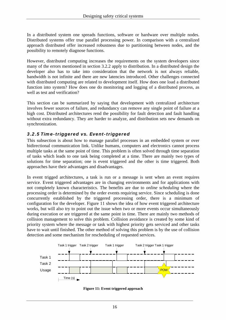
Figure 9: Basic Stand by spare arrangement with n modules
Hybrid redundancy is a combination of static building blocks and dynamic blocks. As seen in Figure 10 NMR and stand by spares are integrated. This approach combines the benefits in both principals. In static redundancy one gets a lot of overhead by the redundancy to maintain majority in voting but gains no downtime. In a dynamic arrangement one can use less overhead but instead there is a time gap before output signal is restored. In this type of arrangement one can detect and switch out the faulty module while the voting element maintains a correct output signal.
Mobule 1
Module 2
Module 3
Spare module n
Switch
Input 1
Input ´2
Input 3
Input n
Fault detector
Votingelement
Output
Figure 10: Hybrid redundancy arrangement
This section has shown the basic arrangements used to design redundancy. However, in these concepts there are components like the fault detector in Figure 10 which still are a single point of failure. This can be taken care of by arranging these concepts in series and parallel monitoring each other.
3.2.4 Distributed vs. Centralized This section describes the basic differences between centralized and distributed system architecture, and the subject is mainly related to computing and how information is treated. In a centralized architecture you try to gather all resources, hardware or software, into one node or single system. The benefit of centralization is the ease of access both for the developer and running system. The access can be subjected to information of data stored, actuators or sensors. On the backside of centralized design is the systems heavy reliance on a few components and possible lack of robustness as of definition in section 2.4. Functions in a centralized design might be depending on single point of failure, and errors might be hard to detect for the system since it’s hard to diagnose ones self.
15
Designing safety critical systems
In a distributed system one spreads functions, software or hardware over multiple nodes. Distributed systems offer true parallel processing power. In comparison with a centralized approach distributed offer increased robustness due to partitioning between nodes, and the possibility to remotely diagnose functions. However, distributed computing increases the requirements on the system developers since many of the errors mentioned in section 3.2.2 apply to distribution. In a distributed design the developer also has to take into consideration that the network is not always reliable, bandwidth is not infinite and there are new latencies introduced. Other challenges connected with distributed computing are related to development itself. How does one load a distributed function into system? How does one do monitoring and logging of a distributed process, as well as test and verification? This section can be summarized by saying that development with centralized architecture involves fewer sources of failure, and redundancy can remove any single point of failure at a high cost. Distributed architectures rend the possibility for fault detection and fault handling without extra redundancy. They are harder to analyze, and distribution sets new demands on synchronization.
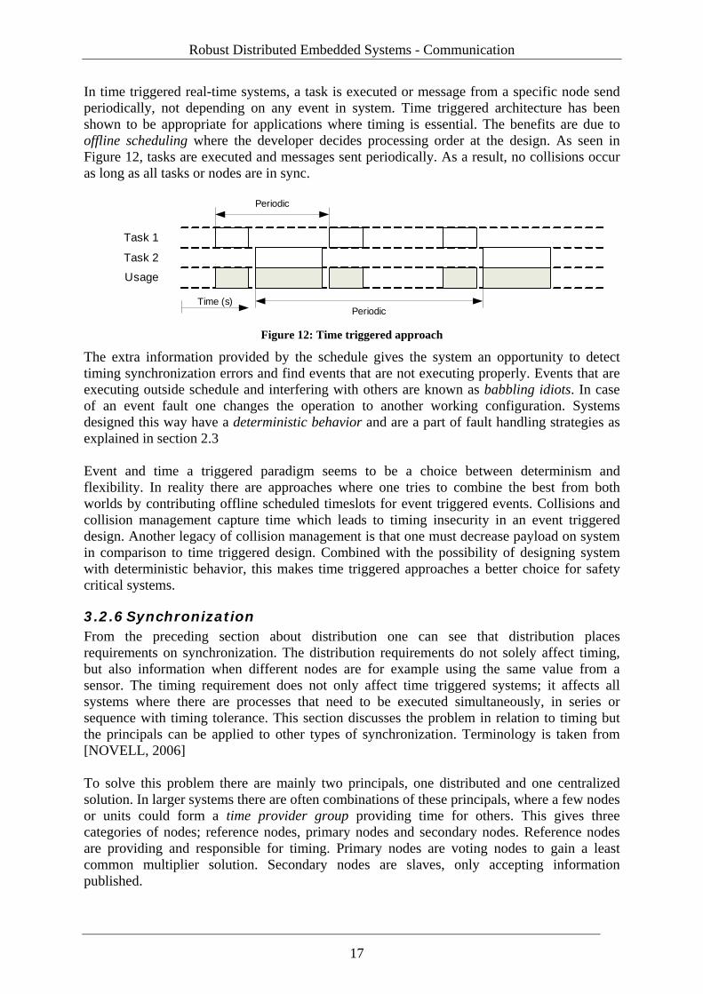
3.2.5 Time-triggered vs. Event-triggered This subsection is about how to manage parallel processes in an embedded system or over bidirectional communication link. Unlike humans, computers and electronics cannot process multiple tasks at the same point of time. This problem is often solved through time separation of tasks which leads to one task being completed at a time. There are mainly two types of solutions for time separation; one is event triggered and the other is time triggered. Both approaches have their advantages and disadvantages. In event trigged architectures, a task is run or a message is sent when an event requires service. Event triggered advantages are in changing environments and for applications with not completely known characteristics. The benefits are due to online scheduling where the processing order is determined by the order events requiring service. Since scheduling is done concurrently established by the triggered processing order, there is a minimum of configuration for the developer. Figure 11 shows the idea of how event triggered architecture works, but will also try to point out the issue when two or more events occur simultaneously during execution or are triggered at the same point in time. There are mainly two methods of collision management to solve this problem. Collision avoidance is created by some kind of priority system where the message or task with highest priority gets serviced and other tasks have to wait until finished. The other method of solving this problem is by the use of collision detection and some mechanism for rescheduling of requested services.
Task 1
Task 2
Usage
Time (s)
Task 1 trigger Task 1 triggerTask 2 trigger Task 2 trigger Task 1 trigger
POW
Figure 11: Event triggered approach
16
Robust Distributed Embedded Systems - Communication
In time triggered real-time systems, a task is executed or message from a specific node send periodically, not depending on any event in system. Time triggered architecture has been shown to be appropriate for applications where timing is essential. The benefits are due to offline scheduling where the developer decides processing order at the design. As seen in Figure 12, tasks are executed and messages sent periodically. As a result, no collisions occur as long as all tasks or nodes are in sync.
Task 1
Task 2
Usage
Time (s)
Periodic
Periodic Figure 12: Time triggered approach
The extra information provided by the schedule gives the system an opportunity to detect timing synchronization errors and find events that are not executing properly. Events that are executing outside schedule and interfering with others are known as babbling idiots. In case of an event fault one changes the operation to another working configuration. Systems designed this way have a deterministic behavior and are a part of fault handling strategies as explained in section 2.3 Event and time a triggered paradigm seems to be a choice between determinism and flexibility. In reality there are approaches where one tries to combine the best from both worlds by contributing offline scheduled timeslots for event triggered events. Collisions and collision management capture time which leads to timing insecurity in an event triggered design. Another legacy of collision management is that one must decrease payload on system in comparison to time triggered design. Combined with the possibility of designing system with deterministic behavior, this makes time triggered approaches a better choice for safety critical systems.
3.2.6 Synchronization From the preceding section about distribution one can see that distribution places requirements on synchronization. The distribution requirements do not solely affect timing, but also information when different nodes are for example using the same value from a sensor. The timing requirement does not only affect time triggered systems; it affects all systems where there are processes that need to be executed simultaneously, in series or sequence with timing tolerance. This section discusses the problem in relation to timing but the principals can be applied to other types of synchronization. Terminology is taken from [NOVELL, 2006] To solve this problem there are mainly two principals, one distributed and one centralized solution. In larger systems there are often combinations of these principals, where a few nodes or units could form a time provider group providing time for others. This gives three categories of nodes; reference nodes, primary nodes and secondary nodes. Reference nodes are providing and responsible for timing. Primary nodes are voting nodes to gain a least common multiplier solution. Secondary nodes are slaves, only accepting information published.
17
Designing safety critical systems
Centralized solutions are forcing master-slave scenarios. A node is designated as master and the node provides time or timing for slave nodes. Slave nodes are configured to poll or receive timing from the master node. The advantage of these kinds of solutions is that they are simple to design and implement. Also, there are fewer synchronization errors since the synchronization hierarchy only has two layers. The disadvantages with this configuration type are similar to other centralized solutions, lack of robustness due to single point of failure possibility. Distributed solutions for synchronization are by nature voting. Two or more nodes are negotiating over the correct time or timing. How an agreement is made differs from solution to solution. In larger systems there will probably be more than two synchronization layers and the synchronization will be more robust due to more sources in case of node failure. Drawbacks are that distributed clock synchronization is harder to implement. In embedded systems these synchronization scenarios can be solved in various ways. Special trigger messages can be sent over the communication media to implement both centralized and distributed synchronization. Prescheduled execution of events as in the time triggered approach will form a distributed synchronization strategy where the nodes will adjust their timing towards the agreed system heartbeat.
3.3 Design methods and tools This section is written in order to get knowledge and summarize a few methods superficially, primary as an orientation to safety critical design but also to speed up general development time.
3.3.1 Software In mechatronical systems, a products´ major behavior is settled by software; therefore software has a big impact on the products´ safety critical aspects. This section will superficially summarize some methods for development of safety critical applications since software faults are permanent. The following quote will try to enlighten the importance of minimization of software faults. “Embedded software applications are very different from classical IT applications. Instead of dealing with data files, they deal with the control of physical phenomena through specific sensor-actuator loops and man-machine interfaces” [Dion et al. 2004]. A simple method is N-version programming technique. Here you use several different implementations of a program. These implementations should all try to realize the same specification and therefore generate the same result. The programs are then executed in series on the same processor or in parallel mode on different processors. Results are then used in any of the redundancy models discussed in section 3.2.3. When comparing the results produced by the different versions, the diversity created by using different implementations gives some protection against systematic faults associated with software but not common faults and transient faults. Many writers uphold that common development languages such as C and Assembler are not suitable for development of safety critical applications. Human factor is a major source of faults, depending on loss of overview due to low abstraction level and loss of strict semantics. This has been stated by both [Storey 1996] and [Dion et al. 2004]. Semantics is the language syntax; how language is expressed.
18
Robust Distributed Embedded Systems - Communication
By the use of tools, code generation tools are a way to get ahold of abstraction level problems. This will be exemplified by two approaches. UML (Unified Modelling Language) is a standardized language with graphical tools for object based development and modelling. UML provides graphical views where diverse aspects of the program are enlightened. In the graphical views diagrams are created, such as state and flow charts, symbolizing the structure. From these diagrams one can generate code with help from different tools to many languages such as C, C++ and ADA [Arvids, 2004]. Another type of modelling environment is tools that describe the process to control instead of the structure of the program. SimuLink from MathWorks, which is an integrated part of MATLAB, is connected to this type of development tool, here you design data flow diagrams, where the connections between the building blocks could carry data or control signals. The diagrams are describing e.g. a control process. SimuLink is combined with an external tool such as TargetLink from dSpace. From the dSpace environment production code is generated directly onto the hardware. An advantage with this solution is that Target-in-a-loop simulation is supported where feedback is possible from hardware platform for comparison of the generated real-time process with the model. [Arvids, 2004] Without bringing any recommendation in choice of programming language or method, it is possible to conclude that there is a huge list of problems that appear during development depending solely on language characteristics. In reality, most development methods and languages are used in safety critical applications, as faults are not only depending on language but how the program or process is designed. Nevertheless it can be said that pure generation of code for embedded systems is rare, due to limitations in e.g. memory and the need for optimized code. Verification and testing of software is complex since fault types can be many. The number of combinations in a complex program that can create a certain error are almost infinite, which makes exhaustive testing impossible. By reconnecting to section 2.3 and fault classifications one can see that there are different methods of testing depending on the fault art. There are among others static testing and dynamic testing, where static testing is structural analysis and dynamic testing is code based. One can also analyze the programs with formal verification, which is a part of formal methods and are mathematically based methods for design and verification. A common method of dynamic testing is probing, where you test individual methods or functions in the code with predefined test cases. These cases are often requirements settled during the design phase of the development. More specifically this is often an input-output test where you feed the function with indata and observe the output provided. The results are then compared with the desired answer to generate a success/failure for that specific function. In case of failure you have to rework code. This technique maps well with the verification traceability in V-model as seen in section 3.1.1.
3.3.2 Simulation and co-design Dependencies and node independencies in distributed control systems and their real-time implementation cause a resulting need for design tools and methods across traditional discipline boundaries.
19
Designing safety critical systems
Problems exist among other things around that there is a difficulty to monitor several network nodes concurrently, and to see all individual registers changes in real time. Other reasons circles around how one evaluates robustness mechanisms in a safety critical applications. As a part of fault removal strategy discussed earlier, simulation for robust system will be a valuable tool. Software based simulation tools are called co-design tools. Truetime by [Henriksson, 2004] is an example of a co-simulation tool for simulation of controller task execution in real-time kernels, network transmissions and continuous plant dynamics. The software application works as a plug-in for Simulink and MatLab from Mathworks. All nodes in a distributed control system can are simulated and monitored from an aggregated view. The software can also be used for fault injection and robustness test.
3.4 Design summary This chapter mainly discusses the left side of the v-model. My definition of robustness means the ability to withstand distortions during runtime. Design of a safety critical system relies on good manners and the usage of a development model for structured workflow, and is more extensive. Development models can be shown to serve as valuable tools for fault avoidance and as a fault removal approach, since faults entering during design are permanent faults. Development models encourage the usage of good specifications. All robustness needs the ability to detect errors and this relies on redundancy. Error detection is accomplished by comparison. All things one desires to protect require their own redundancy; therefore a robust control algorithm needs its own redundancy. Through the usage of more than two redundancy modules one can achieve error masking. A pair comparison only renders possibility for detection, which requires an arrangement. This handling can be graceful degradation or a triggered resend of information. For robust communication, irrespective of network activity or internal application semaphores can be protected by self checking pair solutions, where an algorithm is used in order to calculate a control value. For other building blocks in the embedded system such as hardware, other types of redundancy are required - for instance TMR. Sensor data can be protected by temporal redundancy through multiple measurements in fast sequence, but sensor data must be used in some of the models. From my point of view there is no difference in the safety critical perspective whether the system is time triggered or event triggered. The additional safety added is only due to the execution schedule. Time and timing should be managed by the use of a global clock. From the requirements of the control application the role of the network becomes to transfer information correctly, as well as to be responsible for elicit timing in the distributed embedded system. Evaluation of robustness in distributed embedded systems is completed through testing. Testing can be completed by testing individual components of hardware to processes of software. Diagnostics of distributed applications are difficult due to lack of detail in all nodes. By the use of simulation tools such as true-time where all nodes can be monitored from an aggregated view, monitoring is possible. Tools like these can also be used for fault injection and robustness tests.
20
Robust Distributed Embedded Systems - Communication
4 Real-Time communication for automotive embedded systems
In a distributed embedded system with sensors and actuators separated there is a need for some kind of information exchange due to partitioning. This chapter first discusses the basics of communication and robustness principals in communication and then the five standardized communications busses implemented in the GAST platform.
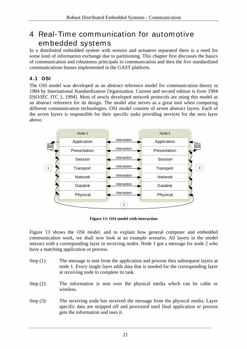
4.1 OSI The OSI model was developed as an abstract reference model for communication theory in 1984 by International Standardization Organization. Current and second edition is from 1994 [ISO/IEC JTC 1, 1994]. Most of newly developed network protocols are using this model as an abstract reference for its design. The model also serves as a great tool when comparing different communication technologies. OSI model consists of seven abstract layers. Each of the seven layers is responsible for their specific tasks providing services for the next layer above.
Application
Presentation
Session
Transport
Network
Datalink
Physical
Application
Presentation
Session
Transport
Network
Datalink
Physical
Node 1 Node 2
Interaction
Interaction
Interaction
Interaction
Interaction
Interaction
Interaction
1
2
3
Figure 13: OSI model with interaction
Figure 13 shows the OSI model, and to explain how general computer and embedded communication work, we shall now look at an example scenario. All layers in the model interact with a corresponding layer in receiving nodes. Node 1 got a message for node 2 who have a matching application or process. Step (1): The message is sent from the application and process thru subsequent layers at
node 1. Every single layer adds data that is needed for the corresponding layer at receiving node to complete its task.
Step (2): The information is sent over the physical media which can be cable or
wireless. Step (3): The receiving node has received the message from the physical media. Layer
specific data are stripped off and processed until final application or process gets the information and uses it.
21
Real-Time communication for automotive embedded systems
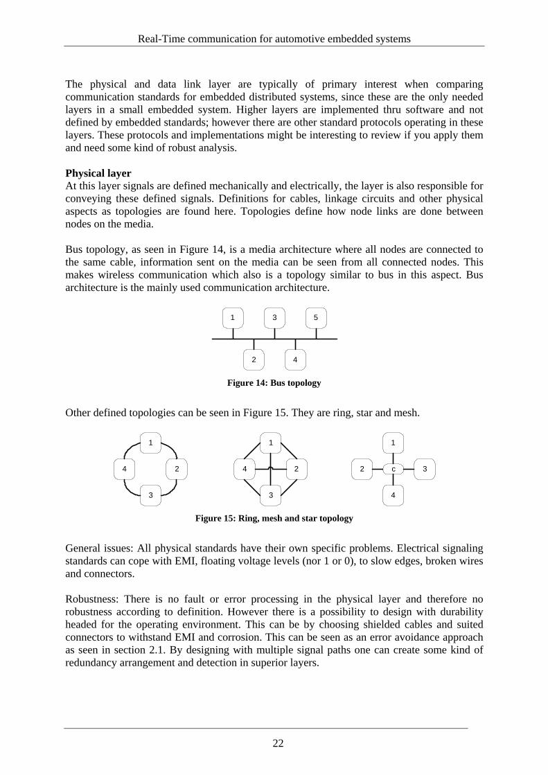
The physical and data link layer are typically of primary interest when comparing communication standards for embedded distributed systems, since these are the only needed layers in a small embedded system. Higher layers are implemented thru software and not defined by embedded standards; however there are other standard protocols operating in these layers. These protocols and implementations might be interesting to review if you apply them and need some kind of robust analysis. Physical layer At this layer signals are defined mechanically and electrically, the layer is also responsible for conveying these defined signals. Definitions for cables, linkage circuits and other physical aspects as topologies are found here. Topologies define how node links are done between nodes on the media. Bus topology, as seen in Figure 14, is a media architecture where all nodes are connected to the same cable, information sent on the media can be seen from all connected nodes. This makes wireless communication which also is a topology similar to bus in this aspect. Bus architecture is the mainly used communication architecture.
1
2
3
4
5
Figure 14: Bus topology
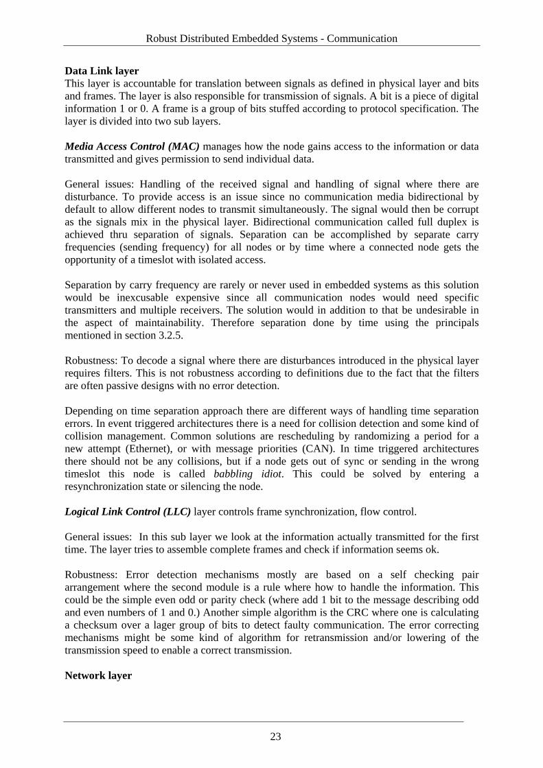
Other defined topologies can be seen in Figure 15. They are ring, star and mesh.
1
2
3
4
1
c 3
4
2
1
2
3
4
Figure 15: Ring, mesh and star topology
General issues: All physical standards have their own specific problems. Electrical signaling standards can cope with EMI, floating voltage levels (nor 1 or 0), to slow edges, broken wires and connectors. Robustness: There is no fault or error processing in the physical layer and therefore no robustness according to definition. However there is a possibility to design with durability headed for the operating environment. This can be by choosing shielded cables and suited connectors to withstand EMI and corrosion. This can be seen as an error avoidance approach as seen in section 2.1. By designing with multiple signal paths one can create some kind of redundancy arrangement and detection in superior layers.
22
Robust Distributed Embedded Systems - Communication
Data Link layer This layer is accountable for translation between signals as defined in physical layer and bits and frames. The layer is also responsible for transmission of signals. A bit is a piece of digital information 1 or 0. A frame is a group of bits stuffed according to protocol specification. The layer is divided into two sub layers. Media Access Control (MAC) manages how the node gains access to the information or data transmitted and gives permission to send individual data. General issues: Handling of the received signal and handling of signal where there are disturbance. To provide access is an issue since no communication media bidirectional by default to allow different nodes to transmit simultaneously. The signal would then be corrupt as the signals mix in the physical layer. Bidirectional communication called full duplex is achieved thru separation of signals. Separation can be accomplished by separate carry frequencies (sending frequency) for all nodes or by time where a connected node gets the opportunity of a timeslot with isolated access. Separation by carry frequency are rarely or never used in embedded systems as this solution would be inexcusable expensive since all communication nodes would need specific transmitters and multiple receivers. The solution would in addition to that be undesirable in the aspect of maintainability. Therefore separation done by time using the principals mentioned in section 3.2.5. Robustness: To decode a signal where there are disturbances introduced in the physical layer requires filters. This is not robustness according to definitions due to the fact that the filters are often passive designs with no error detection. Depending on time separation approach there are different ways of handling time separation errors. In event triggered architectures there is a need for collision detection and some kind of collision management. Common solutions are rescheduling by randomizing a period for a new attempt (Ethernet), or with message priorities (CAN). In time triggered architectures there should not be any collisions, but if a node gets out of sync or sending in the wrong timeslot this node is called babbling idiot. This could be solved by entering a resynchronization state or silencing the node. Logical Link Control (LLC) layer controls frame synchronization, flow control. General issues: In this sub layer we look at the information actually transmitted for the first time. The layer tries to assemble complete frames and check if information seems ok. Robustness: Error detection mechanisms mostly are based on a self checking pair arrangement where the second module is a rule where how to handle the information. This could be the simple even odd or parity check (where add 1 bit to the message describing odd and even numbers of 1 and 0.) Another simple algorithm is the CRC where one is calculating a checksum over a lager group of bits to detect faulty communication. The error correcting mechanisms might be some kind of algorithm for retransmission and/or lowering of the transmission speed to enable a correct transmission. Network layer
23
Real-Time communication for automotive embedded systems
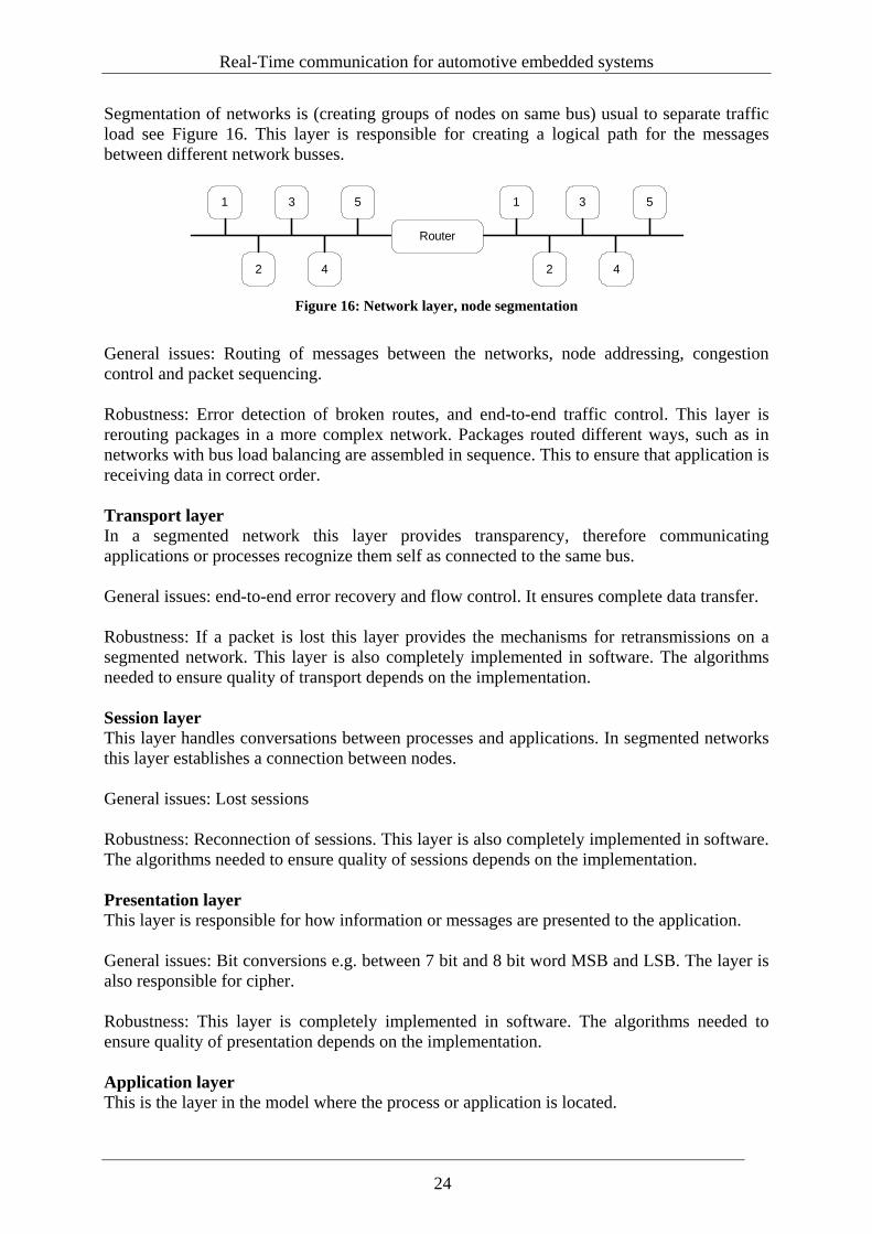
Segmentation of networks is (creating groups of nodes on same bus) usual to separate traffic load see Figure 16. This layer is responsible for creating a logical path for the messages between different network busses.
1
2
3
4
5 1
2
3
4
5
Router
Figure 16: Network layer, node segmentation
General issues: Routing of messages between the networks, node addressing, congestion control and packet sequencing. Robustness: Error detection of broken routes, and end-to-end traffic control. This layer is rerouting packages in a more complex network. Packages routed different ways, such as in networks with bus load balancing are assembled in sequence. This to ensure that application is receiving data in correct order. Transport layer In a segmented network this layer provides transparency, therefore communicating applications or processes recognize them self as connected to the same bus. General issues: end-to-end error recovery and flow control. It ensures complete data transfer. Robustness: If a packet is lost this layer provides the mechanisms for retransmissions on a segmented network. This layer is also completely implemented in software. The algorithms needed to ensure quality of transport depends on the implementation. Session layer This layer handles conversations between processes and applications. In segmented networks this layer establishes a connection between nodes. General issues: Lost sessions Robustness: Reconnection of sessions. This layer is also completely implemented in software. The algorithms needed to ensure quality of sessions depends on the implementation. Presentation layer This layer is responsible for how information or messages are presented to the application. General issues: Bit conversions e.g. between 7 bit and 8 bit word MSB and LSB. The layer is also responsible for cipher. Robustness: This layer is completely implemented in software. The algorithms needed to ensure quality of presentation depends on the implementation. Application layer This is the layer in the model where the process or application is located.
24
Robust Distributed Embedded Systems - Communication
4.2 GAST implemented embedded communication The section is summarizing GAST included protocols.
4.2.1 CAN CAN is an abbreviation for Controller Area Network. It is a serial bus standard developed in 1985 by Robert Bosch GmbH. It was originally designed for electromagnetically noisy environments and particularly for automotive purposes. Today it is used in many control applications even industrial because of its robustness to the subject of noise [KVASER, 2006]. Bit rates up to 1 Mbit/s are possible at networks length below 40 m. Only physical layer and data link layer are standardized in the protocol, OSI layers above for device addressing, and transportation of data blocks larger than one message frame as well as application support has created many manufacturer specific implementations and standards such as seaCAN, Volcano, canKingdom and J1939. OSI Physical Layer: There are several CAN physical layer standards
• ISO 11898-2: CAN high-speed uses a two-wire balanced signaling scheme. It is the most used physical layer in car applications and industrial control networks.
• ISO 11898-3: CAN fault-tolerant (low-speed) • ISO 11992-1: CAN fault-tolerant for truck/trailer communication • SAE J2411: Single-wire CAN (SWC)
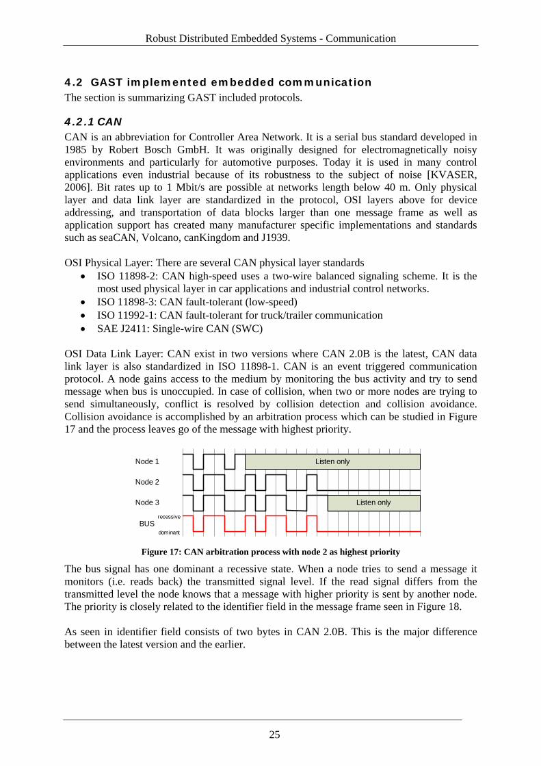
OSI Data Link Layer: CAN exist in two versions where CAN 2.0B is the latest, CAN data link layer is also standardized in ISO 11898-1. CAN is an event triggered communication protocol. A node gains access to the medium by monitoring the bus activity and try to send message when bus is unoccupied. In case of collision, when two or more nodes are trying to send simultaneously, conflict is resolved by collision detection and collision avoidance. Collision avoidance is accomplished by an arbitration process which can be studied in Figure 17 and the process leaves go of the message with highest priority.
Node 1
Node 2
Node 3
BUSrecessive
dominant
Listen only
Listen only
Figure 17: CAN arbitration process with node 2 as highest priority
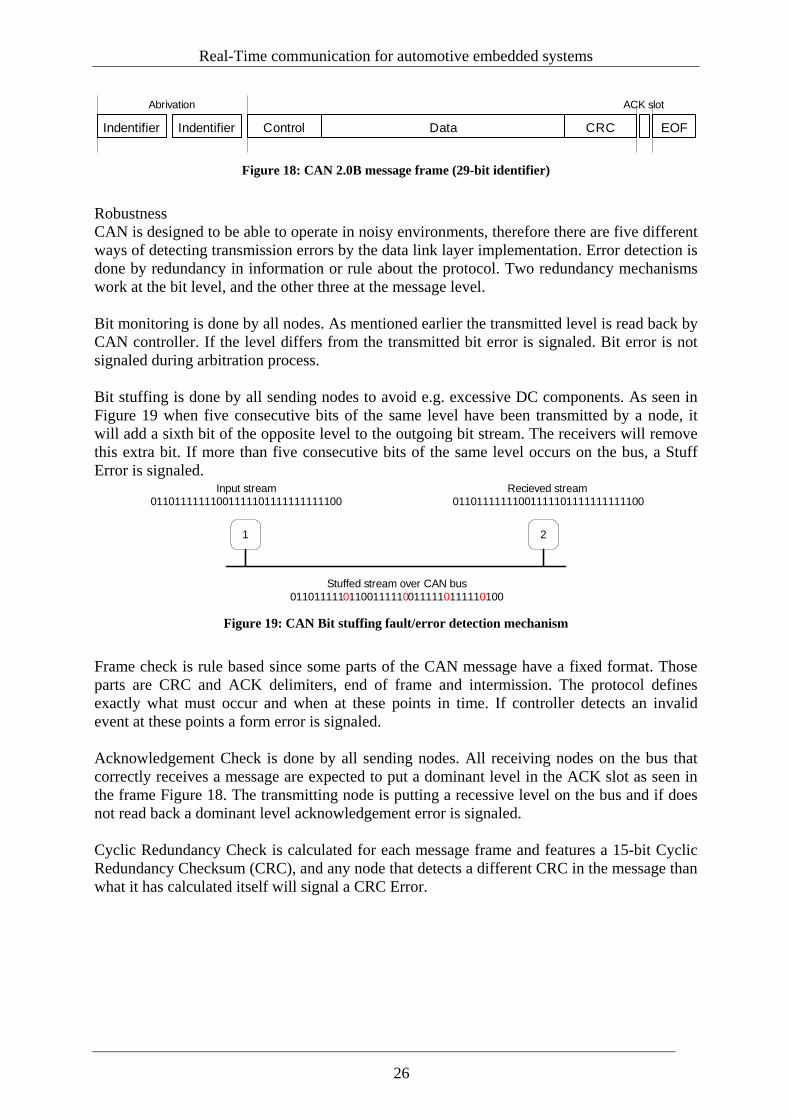
The bus signal has one dominant a recessive state. When a node tries to send a message it monitors (i.e. reads back) the transmitted signal level. If the read signal differs from the transmitted level the node knows that a message with higher priority is sent by another node. The priority is closely related to the identifier field in the message frame seen in Figure 18. As seen in identifier field consists of two bytes in CAN 2.0B. This is the major difference between the latest version and the earlier.
25
Real-Time communication for automotive embedded systems
Indentifier Indentifier Control Data CRC EOF
Abrivation ACK slot
Figure 18: CAN 2.0B message frame (29-bit identifier)
Robustness CAN is designed to be able to operate in noisy environments, therefore there are five different ways of detecting transmission errors by the data link layer implementation. Error detection is done by redundancy in information or rule about the protocol. Two redundancy mechanisms work at the bit level, and the other three at the message level. Bit monitoring is done by all nodes. As mentioned earlier the transmitted level is read back by CAN controller. If the level differs from the transmitted bit error is signaled. Bit error is not signaled during arbitration process.
Bit stuffing is done by all sending nodes to avoid e.g. excessive DC components. As seen in Figure 19 when five consecutive bits of the same level have been transmitted by a node, it will add a sixth bit of the opposite level to the outgoing bit stream. The receivers will remove this extra bit. If more than five consecutive bits of the same level occurs on the bus, a Stuff Error is signaled.
1 2
Input stream01101111111001111101111111111100
Stuffed stream over CAN bus011011111011 001 011 0100011111 1111 111 0
Recieved stream01101111111001111101111111111100
Figure 19: CAN Bit stuffing fault/error detection mechanism
Frame check is rule based since some parts of the CAN message have a fixed format. Those parts are CRC and ACK delimiters, end of frame and intermission. The protocol defines exactly what must occur and when at these points in time. If controller detects an invalid event at these points a form error is signaled. Acknowledgement Check is done by all sending nodes. All receiving nodes on the bus that correctly receives a message are expected to put a dominant level in the ACK slot as seen in the frame Figure 18. The transmitting node is putting a recessive level on the bus and if does not read back a dominant level acknowledgement error is signaled. Cyclic Redundancy Check is calculated for each message frame and features a 15-bit Cyclic Redundancy Checksum (CRC), and any node that detects a different CRC in the message than what it has calculated itself will signal a CRC Error.
26
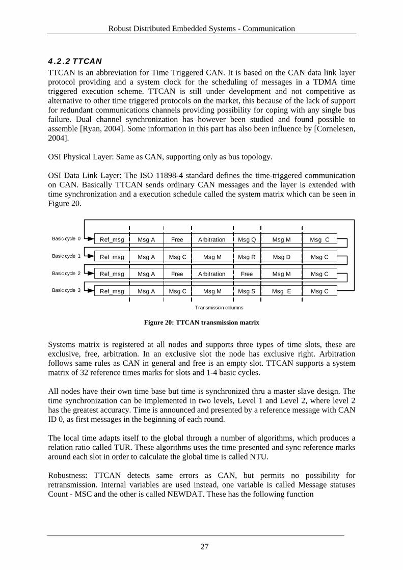
Robust Distributed Embedded Systems - Communication
4.2.2 TTCAN TTCAN is an abbreviation for Time Triggered CAN. It is based on the CAN data link layer protocol providing and a system clock for the scheduling of messages in a TDMA time triggered execution scheme. TTCAN is still under development and not competitive as alternative to other time triggered protocols on the market, this because of the lack of support for redundant communications channels providing possibility for coping with any single bus failure. Dual channel synchronization has however been studied and found possible to assemble [Ryan, 2004]. Some information in this part has also been influence by [Cornelesen, 2004]. OSI Physical Layer: Same as CAN, supporting only as bus topology. OSI Data Link Layer: The ISO 11898-4 standard defines the time-triggered communication on CAN. Basically TTCAN sends ordinary CAN messages and the layer is extended with time synchronization and a execution schedule called the system matrix which can be seen in Figure 20.
Ref_msg Msg A Free Arbitration Msg Q Msg M Msg C
Ref_msg Msg M Msg R Msg D Msg C
Ref_msg Arbitration Free Msg M Msg C
Ref_msg Msg M Msg S Msg E Msg C
Msg A
Msg A
Msg A
Msg C
Free
Msg C
Transmission columns
Basic cycle 0
Basic cycle 1
Basic cycle 2
Basic cycle 3
Figure 20: TTCAN transmission matrix
Systems matrix is registered at all nodes and supports three types of time slots, these are exclusive, free, arbitration. In an exclusive slot the node has exclusive right. Arbitration follows same rules as CAN in general and free is an empty slot. TTCAN supports a system matrix of 32 reference times marks for slots and 1-4 basic cycles. All nodes have their own time base but time is synchronized thru a master slave design. The time synchronization can be implemented in two levels, Level 1 and Level 2, where level 2 has the greatest accuracy. Time is announced and presented by a reference message with CAN ID 0, as first messages in the beginning of each round. The local time adapts itself to the global through a number of algorithms, which produces a relation ratio called TUR. These algorithms uses the time presented and sync reference marks around each slot in order to calculate the global time is called NTU. Robustness: TTCAN detects same errors as CAN, but permits no possibility for retransmission. Internal variables are used instead, one variable is called Message statuses Count - MSC and the other is called NEWDAT. These has the following function
27
Real-Time communication for automotive embedded systems
MSC can contain 4 different status levels based on how the node considers the communication in its own exclusive slot. This variable is sent along with the information in the frame by using the nodes excusive slot. In this way anticipating nodes on the network can become informed. Status levels can be; No errors, Warning, Error and Serve Error Warning is set if a recipient has MSC counter as reached max, or all transmission triggers are not active. This generates an interrupt from the hardware Error is set if MSC counter in sending node has reached max, or if no or not all triggers according to the schedule is activated. This generates an interrupt from the hardware and disables the send function. Server Error is set if application watchdog is activated, bus goes offline, configuration error or no reference messages are received. This sets the communication controller in configuration mode. NEWDAT is used in order to allow applications to compare against the schedule if some node did not succeed to send its message in its slot. Through reading this register applications decide what as is an appropriate measure of execution.
28
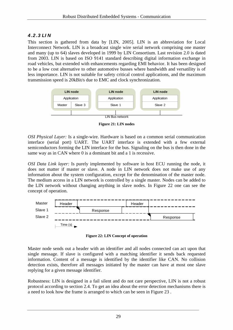
Robust Distributed Embedded Systems - Communication
4.2.3 LIN This section is gathered from data by [LIN, 2005]. LIN is an abbreviation for Local Interconnect Network. LIN is a broadcast single wire serial network comprising one master and many (up to 64) slaves developed in 1999 by LIN Consortium. Last revision 2.0 is dated from 2003. LIN is based on ISO 9141 standard describing digital information exchange in road vehicles, but extended with enhancements regarding EMI behavior. It has been designed to be a low cost alternative to other automotive busses where bandwidth and versatility is of less importance. LIN is not suitable for safety critical control applications, and the maximum transmission speed is 20kBit/s due to EMC and clock synchronization.
LIN nodeLIN nodeLIN node
Master Slave 1 Slave 2Slave 3
Application Application Application
LIN Bus network Figure 21: LIN nodes
OSI Physical Layer: Is a single-wire. Hardware is based on a common serial communication interface (serial port) UART. The UART interface is extended with a few external semiconductors forming the LIN interface for the bus. Signaling on the bus is then done in the same way as in CAN where 0 is a dominant bit and a 1 is recessive. OSI Data Link layer: Is purely implemented by software in host ECU running the node, it does not matter if master or slave. A node in LIN network does not make use of any information about the system configuration, except for the denomination of the master node. The medium access in a LIN network is controlled by a single master. Nodes can be added to the LIN network without changing anything in slave nodes. In Figure 22 one can see the concept of operation.
Master
Slave 1
Slave 2
Header
Response
Time (s)
Header
Response
Figure 22: LIN Concept of operation
Master node sends out a header with an identifier and all nodes connected can act upon that single message. If slave is configured with a matching identifier it sends back requested information. Content of a message is identified by the identifier like CAN. No collision detection exists, therefore all messages initiated by the master can have at most one slave replying for a given message identifier. Robustness: LIN is designed in a fail silent and do not care perspective, LIN is not a robust protocol according to section 2.4. To get an idea about the error detection mechanisms there is a need to look how the frame is arranged to which can be seen in Figure 23 .
29
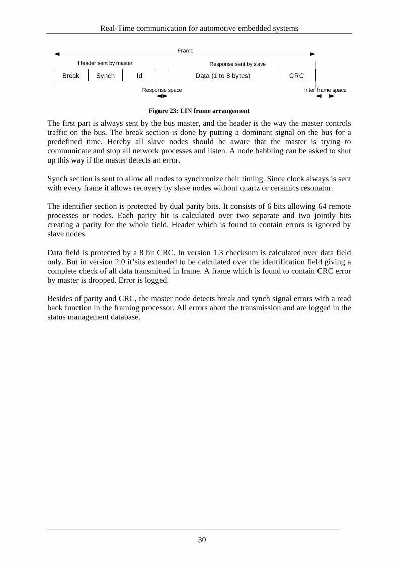
Real-Time communication for automotive embedded systems
Break Synch Data (1 to 8 bytes) CRC
Header sent by master
Id
Response sent by slave
Response space Inter frame space
Frame
Figure 23: LIN frame arrangement
The first part is always sent by the bus master, and the header is the way the master controls traffic on the bus. The break section is done by putting a dominant signal on the bus for a predefined time. Hereby all slave nodes should be aware that the master is trying to communicate and stop all network processes and listen. A node babbling can be asked to shut up this way if the master detects an error. Synch section is sent to allow all nodes to synchronize their timing. Since clock always is sent with every frame it allows recovery by slave nodes without quartz or ceramics resonator. The identifier section is protected by dual parity bits. It consists of 6 bits allowing 64 remote processes or nodes. Each parity bit is calculated over two separate and two jointly bits creating a parity for the whole field. Header which is found to contain errors is ignored by slave nodes. Data field is protected by a 8 bit CRC. In version 1.3 checksum is calculated over data field only. But in version 2.0 it’sits extended to be calculated over the identification field giving a complete check of all data transmitted in frame. A frame which is found to contain CRC error by master is dropped. Error is logged. Besides of parity and CRC, the master node detects break and synch signal errors with a read back function in the framing processor. All errors abort the transmission and are logged in the status management database.
30
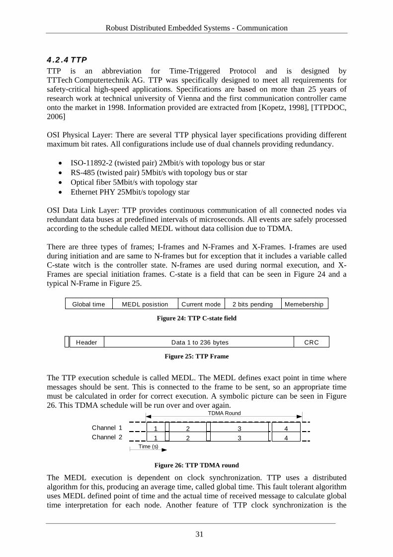
Robust Distributed Embedded Systems - Communication
4.2.4 TTP TTP is an abbreviation for Time-Triggered Protocol and is designed by TTTech Computertechnik AG. TTP was specifically designed to meet all requirements for safety-critical high-speed applications. Specifications are based on more than 25 years of research work at technical university of Vienna and the first communication controller came onto the market in 1998. Information provided are extracted from [Kopetz, 1998], [TTPDOC, 2006] OSI Physical Layer: There are several TTP physical layer specifications providing different maximum bit rates. All configurations include use of dual channels providing redundancy.
• ISO-11892-2 (twisted pair) 2Mbit/s with topology bus or star • RS-485 (twisted pair) 5Mbit/s with topology bus or star • Optical fiber 5Mbit/s with topology star • Ethernet PHY 25Mbit/s topology star
OSI Data Link Layer: TTP provides continuous communication of all connected nodes via redundant data buses at predefined intervals of microseconds. All events are safely processed according to the schedule called MEDL without data collision due to TDMA. There are three types of frames; I-frames and N-Frames and X-Frames. I-frames are used during initiation and are same to N-frames but for exception that it includes a variable called C-state witch is the controller state. N-frames are used during normal execution, and X-Frames are special initiation frames. C-state is a field that can be seen in Figure 24 and a typical N-Frame in Figure 25.
Global time MEDL posistion Current mode 2 bits pending Memebership Figure 24: TTP C-state field
Header Data 1 to 236 bytes CRC
Figure 25: TTP Frame
The TTP execution schedule is called MEDL. The MEDL defines exact point in time where messages should be sent. This is connected to the frame to be sent, so an appropriate time must be calculated in order for correct execution. A symbolic picture can be seen in Figure 26. This TDMA schedule will be run over and over again.
Channel 1Channel 2
Time (s)
1 32
431
24
TDMA Round
Figure 26: TTP TDMA round
The MEDL execution is dependent on clock synchronization. TTP uses a distributed algorithm for this, producing an average time, called global time. This fault tolerant algorithm uses MEDL defined point of time and the actual time of received message to calculate global time interpretation for each node. Another feature of TTP clock synchronization is the
31
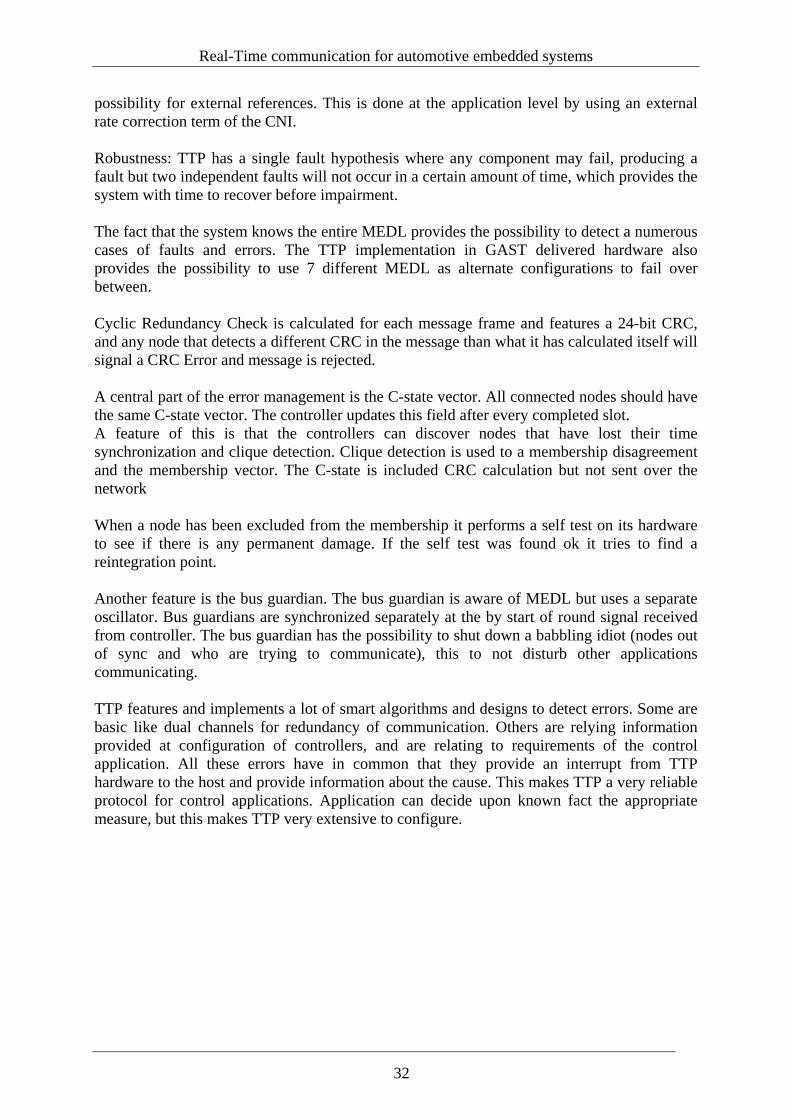
Real-Time communication for automotive embedded systems
possibility for external references. This is done at the application level by using an external rate correction term of the CNI. Robustness: TTP has a single fault hypothesis where any component may fail, producing a fault but two independent faults will not occur in a certain amount of time, which provides the system with time to recover before impairment. The fact that the system knows the entire MEDL provides the possibility to detect a numerous cases of faults and errors. The TTP implementation in GAST delivered hardware also provides the possibility to use 7 different MEDL as alternate configurations to fail over between. Cyclic Redundancy Check is calculated for each message frame and features a 24-bit CRC, and any node that detects a different CRC in the message than what it has calculated itself will signal a CRC Error and message is rejected. A central part of the error management is the C-state vector. All connected nodes should have the same C-state vector. The controller updates this field after every completed slot. A feature of this is that the controllers can discover nodes that have lost their time synchronization and clique detection. Clique detection is used to a membership disagreement and the membership vector. The C-state is included CRC calculation but not sent over the network When a node has been excluded from the membership it performs a self test on its hardware to see if there is any permanent damage. If the self test was found ok it tries to find a reintegration point. Another feature is the bus guardian. The bus guardian is aware of MEDL but uses a separate oscillator. Bus guardians are synchronized separately at the by start of round signal received from controller. The bus guardian has the possibility to shut down a babbling idiot (nodes out of sync and who are trying to communicate), this to not disturb other applications communicating. TTP features and implements a lot of smart algorithms and designs to detect errors. Some are basic like dual channels for redundancy of communication. Others are relying information provided at configuration of controllers, and are relating to requirements of the control application. All these errors have in common that they provide an interrupt from TTP hardware to the host and provide information about the cause. This makes TTP a very reliable protocol for control applications. Application can decide upon known fact the appropriate measure, but this makes TTP very extensive to configure.
32
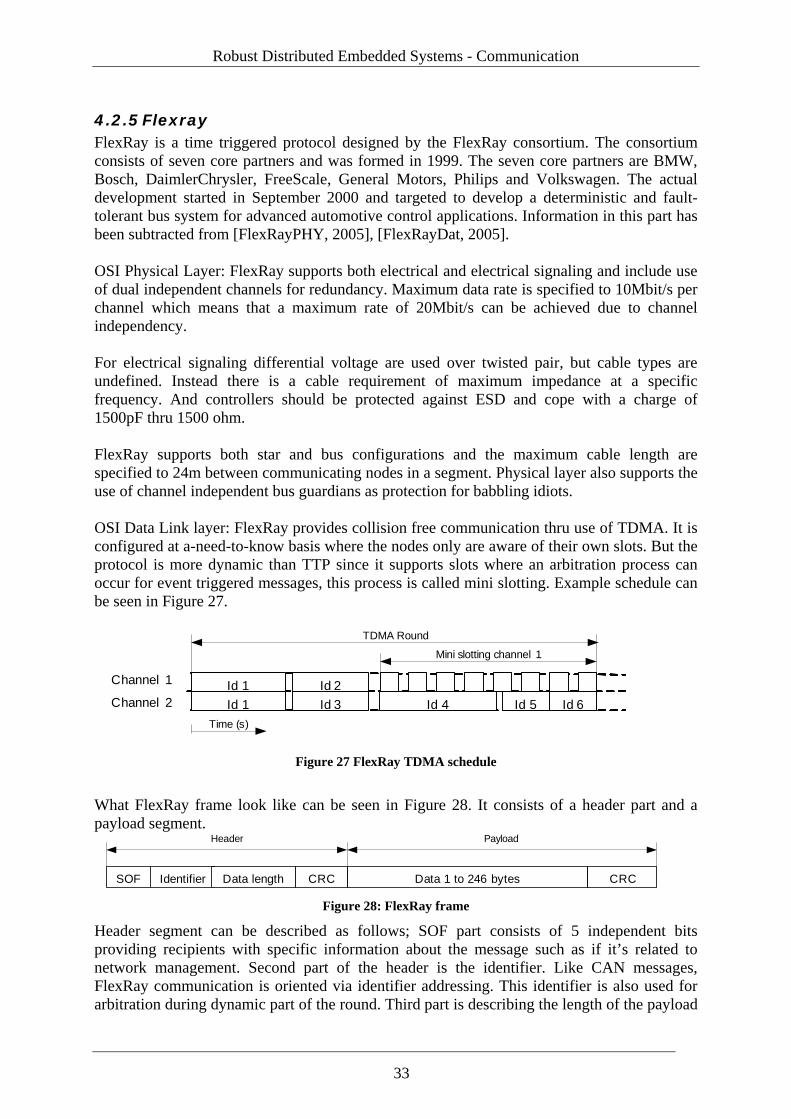
Robust Distributed Embedded Systems - Communication
4.2.5 Flexray FlexRay is a time triggered protocol designed by the FlexRay consortium. The consortium consists of seven core partners and was formed in 1999. The seven core partners are BMW, Bosch, DaimlerChrysler, FreeScale, General Motors, Philips and Volkswagen. The actual development started in September 2000 and targeted to develop a deterministic and fault-tolerant bus system for advanced automotive control applications. Information in this part has been subtracted from [FlexRayPHY, 2005], [FlexRayDat, 2005]. OSI Physical Layer: FlexRay supports both electrical and electrical signaling and include use of dual independent channels for redundancy. Maximum data rate is specified to 10Mbit/s per channel which means that a maximum rate of 20Mbit/s can be achieved due to channel independency. For electrical signaling differential voltage are used over twisted pair, but cable types are undefined. Instead there is a cable requirement of maximum impedance at a specific frequency. And controllers should be protected against ESD and cope with a charge of 1500pF thru 1500 ohm. FlexRay supports both star and bus configurations and the maximum cable length are specified to 24m between communicating nodes in a segment. Physical layer also supports the use of channel independent bus guardians as protection for babbling idiots. OSI Data Link layer: FlexRay provides collision free communication thru use of TDMA. It is configured at a-need-to-know basis where the nodes only are aware of their own slots. But the protocol is more dynamic than TTP since it supports slots where an arbitration process can occur for event triggered messages, this process is called mini slotting. Example schedule can be seen in Figure 27.
Channel 1
Channel 2Time (s)
Id 1Id 3 Id 4Id 1Id 2
Id 5
TDMA Round
Id 6
Mini slotting channel 1
Figure 27 FlexRay TDMA schedule
What FlexRay frame look like can be seen in Figure 28. It consists of a header part and a payload segment.
Identifier Data 1 to 246 bytesCRCData length CRCSOF
PayloadHeader
Figure 28: FlexRay frame
Header segment can be described as follows; SOF part consists of 5 independent bits providing recipients with specific information about the message such as if it’s related to network management. Second part of the header is the identifier. Like CAN messages, FlexRay communication is oriented via identifier addressing. This identifier is also used for arbitration during dynamic part of the round. Third part is describing the length of the payload
33
Real-Time communication for automotive embedded systems
segment and the fourth part is a CRC checksum calculated over the preceding header information. Second part of frame is Payload segment which contains the information to be transmitted in variable length data segment. The payload part is ended with a 24 bit CRC calculated over the complete frame. To ensure proper execution of schedule FlexRay are using a distributed Clock synchronization algorithm producing an average time, called global time. This fault tolerant algorithm uses execution schedule cycles, bit times micro and macro tick to calculate global time interpretation for each node. Robustness: FlexRay has the following fault hypothesis it should be able to withstand:
• Single fault hypothesis • For clock synchronization less than a third could be faulty
FlexRay is a time triggered protocol witch means that there will be no collisions. Data is protected by CRC so remote nodes can validate transmission. The protocol also supports redundant channels for increased fault tolerance, and all bits in every message are scanned several times to withstand transients. Like TTCAN FlexRay does not permit retransmissions and are instead using a status register, and is not sent along with the messages but used for local diagnosis and communication degradation. These four modes in the FSEV register can be summarized as status levels and can be; Normal operation, Warning, Error and Fatal Error
• When a warning is set controller continues with full operation • When Error is set transmissions are stopped and host informed • When fatal error is set all operations are disabled
34
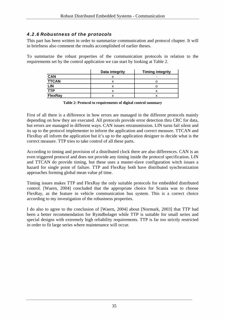
Robust Distributed Embedded Systems - Communication
4.2.6 Robustness of the protocols This part has been written in order to summarize communication and protocol chapter. It will in briefness also comment the results accomplished of earlier theses. To summarize the robust properties of the communication protocols in relation to the requirements set by the control application we can start by looking at Table 2.
Data integrity Timing integrityCAN x -TTCAN x oLIN x oTTP x xFlexRay x x
Table 2: Protocol to requirements of digital control summary
First of all there is a difference in how errors are managed in the different protocols mainly depending on how they are executed. All protocols provide error detection thru CRC for data, but errors are managed in different ways. CAN issues retransmission. LIN turns fail silent and its up to the protocol implementer to inform the application and correct measure. TTCAN and FlexRay all inform the application but it’s up to the application designer to decide what is the correct measure. TTP tries to take control of all these parts. According to timing and provision of a distributed clock there are also differences. CAN is an even triggered protocol and does not provide any timing inside the protocol specification. LIN and TTCAN do provide timing, but these uses a master-slave configuration witch issues a hazard for single point of failure. TTP and FlexRay both have distributed synchronization approaches forming global mean value pf time. Timing issues makes TTP and FlexRay the only suitable protocols for embedded distributed control. [Waern, 2004] concluded that the appropriate choice for Scania was to choose FlexRay, as the feature in vehicle communication bus system. This is a correct choice according to my investigation of the robustness properties. I do also to agree to the conclusion of [Waern, 2004] about [Normark, 2003] that TTP had been a better recommendation for Rymdbolaget while TTP is suitable for small series and special designs with extremely high reliability requirements. TTP is far too strictly restricted in order to fit large series where maintenance will occur.
35

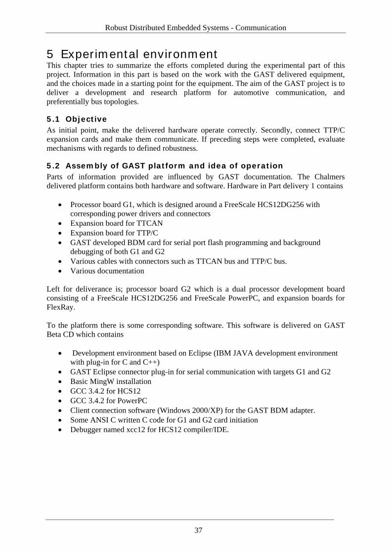
Robust Distributed Embedded Systems - Communication
5 Experimental environment This chapter tries to summarize the efforts completed during the experimental part of this project. Information in this part is based on the work with the GAST delivered equipment, and the choices made in a starting point for the equipment. The aim of the GAST project is to deliver a development and research platform for automotive communication, and preferentially bus topologies.
5.1 Objective As initial point, make the delivered hardware operate correctly. Secondly, connect TTP/C expansion cards and make them communicate. If preceding steps were completed, evaluate mechanisms with regards to defined robustness.
5.2 Assembly of GAST platform and idea of operation Parts of information provided are influenced by GAST documentation. The Chalmers delivered platform contains both hardware and software. Hardware in Part delivery 1 contains
• Processor board G1, which is designed around a FreeScale HCS12DG256 with corresponding power drivers and connectors
• Expansion board for TTCAN • Expansion board for TTP/C • GAST developed BDM card for serial port flash programming and background
debugging of both G1 and G2 • Various cables with connectors such as TTCAN bus and TTP/C bus. • Various documentation
Left for deliverance is; processor board G2 which is a dual processor development board consisting of a FreeScale HCS12DG256 and FreeScale PowerPC, and expansion boards for FlexRay. To the platform there is some corresponding software. This software is delivered on GAST Beta CD which contains
• Development environment based on Eclipse (IBM JAVA development environment with plug-in for C and C++)
• GAST Eclipse connector plug-in for serial communication with targets G1 and G2 • Basic MingW installation • GCC 3.4.2 for HCS12 • GCC 3.4.2 for PowerPC • Client connection software (Windows 2000/XP) for the GAST BDM adapter. • Some ANSI C written C code for G1 and G2 card initiation • Debugger named xcc12 for HCS12 compiler/IDE.
37
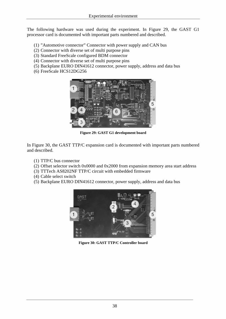
Experimental environment
The following hardware was used during the experiment. In Figure 29, the GAST G1 processor card is documented with important parts numbered and described.
(1) ”Automotive connector” Connector with power supply and CAN bus (2) Connector with diverse set of multi purpose pins (3) Standard FreeScale configured BDM connector (4) Connector with diverse set of multi purpose pins (5) Backplane EURO DIN41612 connector, power supply, address and data bus (6) FreeScale HCS12DG256
Figure 29: GAST G1 development board
In Figure 30, the GAST TTP/C expansion card is documented with important parts numbered and described.
(1) TTP/C bus connector (2) Offset selector switch 0x0000 and 0x2000 from expansion memory area start address (3) TTTech AS8202NF TTP/C circuit with embedded firmware (4) Cable select switch (5) Backplane EURO DIN41612 connector, power supply, address and data bus
Figure 30: GAST TTP/C Controller board
38
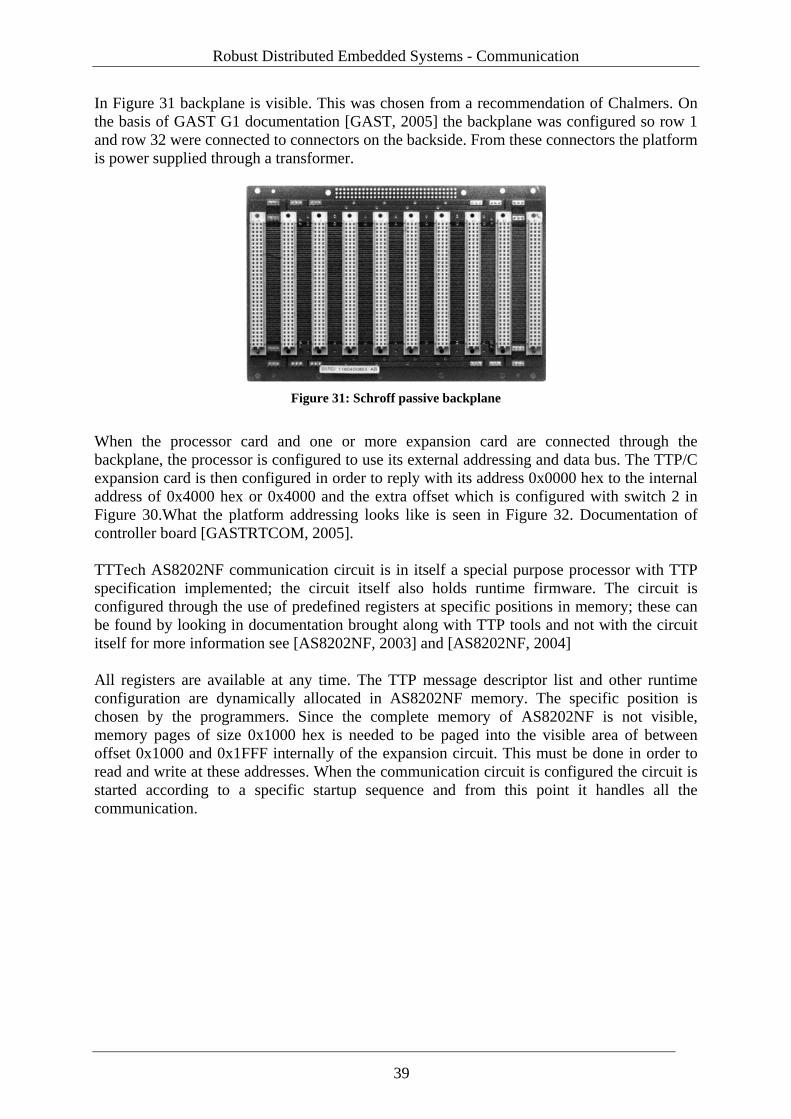
Robust Distributed Embedded Systems - Communication
In Figure 31 backplane is visible. This was chosen from a recommendation of Chalmers. On the basis of GAST G1 documentation [GAST, 2005] the backplane was configured so row 1 and row 32 were connected to connectors on the backside. From these connectors the platform is power supplied through a transformer.
Figure 31: Schroff passive backplane
When the processor card and one or more expansion card are connected through the backplane, the processor is configured to use its external addressing and data bus. The TTP/C expansion card is then configured in order to reply with its address 0x0000 hex to the internal address of 0x4000 hex or 0x4000 and the extra offset which is configured with switch 2 in Figure 30.What the platform addressing looks like is seen in Figure 32. Documentation of controller board [GASTRTCOM, 2005]. TTTech AS8202NF communication circuit is in itself a special purpose processor with TTP specification implemented; the circuit itself also holds runtime firmware. The circuit is configured through the use of predefined registers at specific positions in memory; these can be found by looking in documentation brought along with TTP tools and not with the circuit itself for more information see [AS8202NF, 2003] and [AS8202NF, 2004] All registers are available at any time. The TTP message descriptor list and other runtime configuration are dynamically allocated in AS8202NF memory. The specific position is chosen by the programmers. Since the complete memory of AS8202NF is not visible, memory pages of size 0x1000 hex is needed to be paged into the visible area of between offset 0x1000 and 0x1FFF internally of the expansion circuit. This must be done in order to read and write at these addresses. When the communication circuit is configured the circuit is started according to a specific startup sequence and from this point it handles all the communication.
39
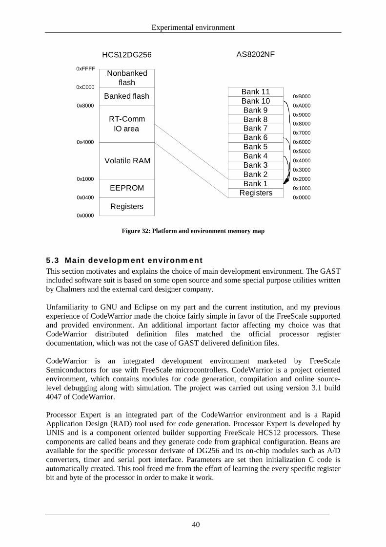
Experimental environment
Registers
EEPROM
Volatile RAM
RT-CommIO area
Banked flash
Nonbanked flash
RegistersBank 1Bank 2Bank 3
0x0000
Bank 4Bank 5Bank 6Bank 7Bank 8Bank 9Bank 10Bank 11
0x0400
0x1000
0x4000
0x8000
0xC000
0xFFFF
0x0000
0x1000
0x2000
HCS12DG256 AS8202NF
0x3000
0x4000
0x5000
0x6000
0x7000
0x80000x9000
0xA000
0xB000
Figure 32: Platform and environment memory map
5.3 Main development environment This section motivates and explains the choice of main development environment. The GAST included software suit is based on some open source and some special purpose utilities written by Chalmers and the external card designer company. Unfamiliarity to GNU and Eclipse on my part and the current institution, and my previous experience of CodeWarrior made the choice fairly simple in favor of the FreeScale supported and provided environment. An additional important factor affecting my choice was that CodeWarrior distributed definition files matched the official processor register documentation, which was not the case of GAST delivered definition files. CodeWarrior is an integrated development environment marketed by FreeScale Semiconductors for use with FreeScale microcontrollers. CodeWarrior is a project oriented environment, which contains modules for code generation, compilation and online source-level debugging along with simulation. The project was carried out using version 3.1 build 4047 of CodeWarrior. Processor Expert is an integrated part of the CodeWarrior environment and is a Rapid Application Design (RAD) tool used for code generation. Processor Expert is developed by UNIS and is a component oriented builder supporting FreeScale HCS12 processors. These components are called beans and they generate code from graphical configuration. Beans are available for the specific processor derivate of DG256 and its on-chip modules such as A/D converters, timer and serial port interface. Parameters are set then initialization C code is automatically created. This tool freed me from the effort of learning the every specific register bit and byte of the processor in order to make it work.
40
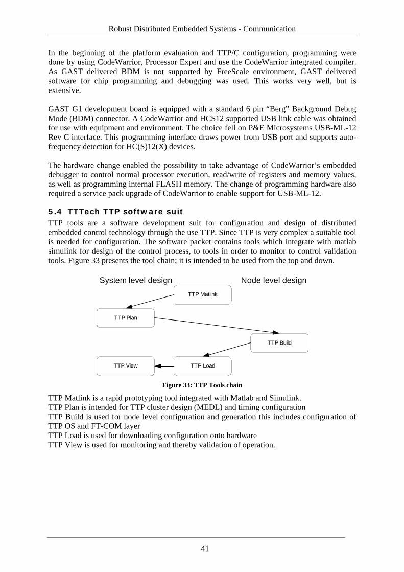
Robust Distributed Embedded Systems - Communication
In the beginning of the platform evaluation and TTP/C configuration, programming were done by using CodeWarrior, Processor Expert and use the CodeWarrior integrated compiler. As GAST delivered BDM is not supported by FreeScale environment, GAST delivered software for chip programming and debugging was used. This works very well, but is extensive. GAST G1 development board is equipped with a standard 6 pin “Berg” Background Debug Mode (BDM) connector. A CodeWarrior and HCS12 supported USB link cable was obtained for use with equipment and environment. The choice fell on P&E Microsystems USB-ML-12 Rev C interface. This programming interface draws power from USB port and supports auto-frequency detection for HC(S)12(X) devices. The hardware change enabled the possibility to take advantage of CodeWarrior’s embedded debugger to control normal processor execution, read/write of registers and memory values, as well as programming internal FLASH memory. The change of programming hardware also required a service pack upgrade of CodeWarrior to enable support for USB-ML-12.
5.4 TTTech TTP software suit TTP tools are a software development suit for configuration and design of distributed embedded control technology through the use TTP. Since TTP is very complex a suitable tool is needed for configuration. The software packet contains tools which integrate with matlab simulink for design of the control process, to tools in order to monitor to control validation tools. Figure 33 presents the tool chain; it is intended to be used from the top and down.
TTP Matlink
TTP Plan
TTP Build
TTP LoadTTP View
System level design Node level design
Figure 33: TTP Tools chain
TTP Matlink is a rapid prototyping tool integrated with Matlab and Simulink. TTP Plan is intended for TTP cluster design (MEDL) and timing configuration TTP Build is used for node level configuration and generation this includes configuration of TTP OS and FT-COM layer TTP Load is used for downloading configuration onto hardware TTP View is used for monitoring and thereby validation of operation.
41
Experimental environment
5.5 Experimental environment and summary of work Based on collected documentation, the following steps where taken when hardware was assembled. Because of all the connectors and pins, it was a natural choice to assemble the equipment in a case due to the risk of hardware short circuit. The case was originally adapted for some other experiment, so the case was modified for backplane contacts to conform to the guide tails that exist internally. Moreover, the backplane was configured for power supply of the whole platform powered via row 1 and 32. As described earlier, CodeWarrior was used and the software environment for coding and flashing has been configured. In order for GAST equipment to operate correctly with USB-ML-12, the removal of lock bit (processor registry change) and the elimination of GAST embedded firmware on controllers was needed. CodeWarrior development environment works well with GAST G1 considering programming flashing and debugging. I have written definition files on the basis of TTP circuit documentation but verification failed when reading and writing to AS8202NF. I spent a lot of time on rewriting these definition files between ANSI C and CodeWarrior specific declaration, since I was uncertain if my work was accurate, due to unfamiliarity to pointers and structures in C. Later it has been shown that [Sjoholm, 2006] experienced the same problem. Their solution was to shorten the backplane in order to get rid of its capacitive behavior. This was not an option in my case. TTTech tools that were used for experiments to generate configuration of TTP from the TTP tools suit were TTP plan and TTP build. These is tools are strictly directed towards distributed control and not suitable for simple applications. TTP configuration using TTP plan require specification of timing deadlines related to the requirements from the control process. The software is strictly aimed on TTTech delivered hardware solutions, and moreover not intended for GAST and neither tested on the platform. TTTech has not tested the platform themselves with the software suit although they incorporated as a participant in GAST project. My evaluation of TTP Plan generated code shows that there are possibilities to extract configuration information form tool for configuration of platform. License problems seemed to be the essence of this thesis, and engaged a lot of time during the progress of this project. All software that was included in the development environment had some part of this. Through collaboration between FreeScale and Royal Institute of Technology, time bombed licenses were to be used during the development in CodeWarrior. Delivered licenses worked well, but there were latencies between expired licenses and working ones which periodically stopped progress. TTTech toolkit also had problems. This development suit uses computer specific generated license keys, which did not turn out correctly and therefore took time before an operational license was delivered. Another problem which actually contributed to the refinement of TTP tools was a bug disclosing itself in occasional unique installations, like my installation. The bug exposed itself by using all available processor power to launch TTINIT.BIN as soon as any TTTools application was launched. TTech presented a workaround by renaming or deleting the file. TTINIT.BIN is their splash screen located in the installation directory.
42
Robust Distributed Embedded Systems - Communication
5.6 Summary of experiences from the GAST project I found that the GAST documentation was inadequate, which meant that my time was spent incorrectly. In order to illustrate this, the following can be mentioned: .
• Faulty documentation of specific G1 connector • G1 processor card is only executed at 8MHz; this is only referred to as a setting
intended for delivered flashing program. To summarize hardware, GAST delivered platform has no real restrictions, which is positive. From my point of view there is a small scarcity in a lack of a few diodes and buttons on the development card for easy debugging of smaller application development. I also find that the automotive connector is a doubtful design element. GAST delivered definition files does not match the official processor register documentation. GAST delivered software for chip programming and debugging was tested, these programs work very well, but provide extra work in comparison to CodeWarrior solution.
43

Robust Distributed Embedded Systems - Communication
6 Summary and conclusion Embedded systems do not differ that much from traditional computers. An embedded system still consists of a processor and electronics, even if the system itself is working in a unique environment with tighter requirements on performance. With a starting point in my definition of robustness for distributed embedded control systems, and who is putting demands on the network, the requirement of the network is to transfer information correctly as well as being responsible for elicit timing and time in the distributed system. All error detection and possibilities to detect errors are created by redundancy. In all studied embedded protocols, the information is protected by a diverse set of algorithms for redundancy, among others CRC, which makes it possible to detect transmission errors hidden in the information. However, there are considerations about how and where timing should be managed. In a discussion about distributed or centralized solutions, all centralized solutions disappear due to single point of failure in a robust system. Essential questions are if the network should provide timing or distribute time from some other source, and if timing should be implemented in hardware or software. Implementation in hardware gives better performance but less flexibility. There is however often an advantage to implementing standard solutions in hardware. The question is if time triggered architectures is the answer to the clock problem. It is natural to choose such architecture with the technology of today since time is periodically by default, which gives reference marks to adjust timing around. No major event triggered solution provides reference marks for timing, which make them unsuitable for robust safety critical systems if the timing should be implemented in hardware. That time triggered architectures should be better fitted and safer is on the other hand doubtful. The extra protection is not due to the timed execution or loss of collisions. Rather, it is due to the fact that the run schedule provides redundant information about other nodes or processes, so remote nodes can detect if a remote node or process is dead or unsynchronized. This can be managed in other ways such as time stamped data. This provides the single control process with the opportunity to decide by it self what the necessary measure is. This is not a responsibility of the network. A discussion about robust communication protocols for the future can be continued, since there are more aspects in embedded communication. From the view of certification, time triggered solutions are easier to certificate than corresponding event triggered ones. And from the view of maintainability, automotive time triggered protocols of today get trapped. They do not provide any flexibility and they are too complicated to configure for a non-control related application. Neither do they support AD-HOC networking, which is an important property considering that the common workshop employee or control designer should not be forced to deep systems engineering for exchange or addition of generalized nodes or components. How the future protocol and solution for distributed systems looks is impossible to say. My guess is an event triggered bus where every frame or packet contains time information for a distributed clock on the bus. This does not prevent the usage of redundant communication busses or mechanisms for handling a babbling idiot. Collision management in event triggered systems occupies time, which in reality creates problems in the amount of possible bus load. Nodes and connected communication equipment are also generally increasing in numbers. To
45
Summary and conclusion
decrease bus load if communication speed is not improved, forces designers to split buses into segments in a greater extent. A result of this is also the introduction of a network layer form ISO model for addressing purposes. The theoretical discussion about robustness can relate to my failed experiment. The connection between the microcontroller and expansion cards occurs from the view of the processor on external addressing and data busses. The microcontroller provides the timing but the bus architecture does not contain any redundancy information. The data bus has no opportunity to verify information; this must be done manually via software. My verification of the written information showed random flips where individual bits got stuck in high position. This is the same problem [Sjoholm, 2006] encountered in a different experiment using the platform. Due to its openness, the platform has a future for development and research in the field of distributed embedded systems. However there is a lack of drivers for the platform integrated network protocols. This must be attended to if the platform shall have any significance before the technology is out of date. My evaluation of TTP Plan generated code shows that there are possibilities to extract configuration information form tool for configuration of platform. Suggestions and recommendations for future papers include the analysis of the signal in the data bus, the possible design of a filter for use of current assembly and the design of some kind of extraction script for use of TTP plan.
46
Robust Distributed Embedded Systems - Communication
7 Reference [Arvids, 2004] Mikael Arvids, “Tools For Developing Real-Time Software –
Modelling, Code Generation and RTOS Configuration”, Master thesis, 2004, MMK 2004:35 MDA 221
[AS8202NF, 2003] TTChip Entwicklungsges.m.b.H., “TTP/C Controller C2NF Controller-Host Interface Description, Document Firmware Version 2.0.3” Document edition 1.1.5 of 23-Nov-2003, Document number D-032-S-10-041
[AS8202NF, 2004] TTChip Entwicklungsges.m.b.H, “TTP/C Controller C2NF Controller Schedule (MEDL) Structure Document Firmware Version 2.0.3”, Document edition 1.1.8 of 8-Jan-2004 Document number D-032-S-10-040
[Chen, 2001] DeJiu Chen, “Architecture for systematic development of mechatronics software systems”, Licentiate thesis, 2001, ISSN: 1400-1179, TRITA-MMK-2001:06
[Cornelesen, 2004] Dan Cornelesen and Patrik Dahlqvist , “Development of a Safety Critical Mechatronical System Used as Demonstrator for GAST”, Master thesis, 2004, MMK 2004:xx MDA xxx
[Dion et al., 2004] Bernard Dion, Thierry Le Segent, Bruno Martin, Herbert Griebel, “Model-based development for time-triggered architectures”,http://www.tttech.com/technology/docs/history/DASC_2004-10-TTA_SCADE.pdf, Accessed 2005-12-01
[ISO/IEC JTC 1, 1994] ISO/IEC 7498-1:1994, “Information technology – Open Systems Interconnection – Basic Reference Model: The Basic model”, ISO/IEC Copyright Office, 1996
[GASTG1, 2005] GAST G1 documentation provided on GAST BETA CDROM
[GASTRTCOM, 2005] GAST RTCOM documentation provided on GAST BETA CDROM
[FlexRayPHY, 2005] FlexRay electrical physical layer specification v2.1, obtained at www.flexray.com, 2005-11-14
[FlexRayDat, 2005] FlexRay protocol specification v2.1, obtained at www.flexray.com, 2005-11-14
[Henriksson, 2004] Dan Henriksson, Anton Cervin, ”Truetime 1.2 – Reference Manual”, http://www.control.lth.se/~dan/truetime/, Accessed 2006-01-09.
47
Reference
[Kopetz, 1998] Herman Kopetz, "A Comparision of CAN and TTP", www.tttech.com/technology/docs/protocol_comparisons/HK_1998-09-Comparison_CAN-TTP.pdf
[Larses, 2005] Ola Larses, “Architecting and modeling automotive embedded systems“, Doctoral thesis, 2005, ISSN: 1400-1179, TRITA-MMK-2005:31
[LIN, 2005] http://www.lin-subbus.org, Accessed: 2005-11-14, lin_bus.pdf
[Ljung, 1989] Lennart Ljung, Torkel Glad, “Reglerteknik – grundläggande teori”, Student litteratur, 1989, ISBN 91-44-17892-1
[NatEnc, 2005] http://www.ne.se/jsp/search/article.jsp?i_art_id=210810, Accessed 2005-12-20
[Normark, 2003] Martin Normark, “Intern Realtidskommunikation i framtida svenska satelliter”, Master thesis, 2004, MMK 2003:29 MDA 197
[NOVELL, 2006] http://www.novell.com/documentation, Accessed 2006-10-10.
[Palbus, 2001a] http://www.sp.se/electronics/RnD/palbus/reports/PALBUS_10_10.pdf, Accessed 2006-11-10.
[Rushby, 2002] John Rushby, “A Comparison of Bus Architectures for Safety-Critical Embedded Systems”, SRI International, Tech rep. June 2002
[Ryan, 2004] Collin Ryan, Donald Heffernan, Gabriel Leen, “Clock synchronization on multiple TTCAN network channels”, Microprocessors and Microsystems 28, 2004, 135-146
[Sjoholm, 2006] Andreas Sjöholm, Christian Archer, “Membership implementations on time triggered architectures”, Master thesis, 2006, Chalmers Univeristy of Technology
[Storey, 1996] Neil Storey, “Safety-critical computer systems”, Addison Wesley Longman Ltd, 1996, ISBN: 0-201-42787-7
[TTPDOC, 2006] DI Georg Stroeger, Information provided during workshop Vienna 13 & 14 March 2006
[WikiPedia, 2005a] http://en.wikipedia.org/wiki/Mechatronic, Accessed 2005-12-20
[WikiPedia, 2005b] http://en.wikipedia.org/wiki/Embedded_system,Accessed 2005-12-20
[WikiPedia, 2005c] http://en.wikipedia.org/wiki/Robustness, Accessed 2005-12-22
48
Robust Distributed Embedded Systems - Communication
[Wikipedia, 2006a] http://en.wikipedia.org/wiki/Waterfall_model, Accessed 2006-06-06
[Wikipedia, 2006b] http://en.wikipedia.org/wiki/Spiral_model, Accessed 2006-06-06
[Waern, 2003] Michael Waern, “Real-Time Communication – Evaluation of Protocols for Automotive Systems”, Master thesis, 2003 MMK 2003:57 MDA 213
[KVASER, 2006] http://www.kvaser.se, accessed: 2006-09-01
49

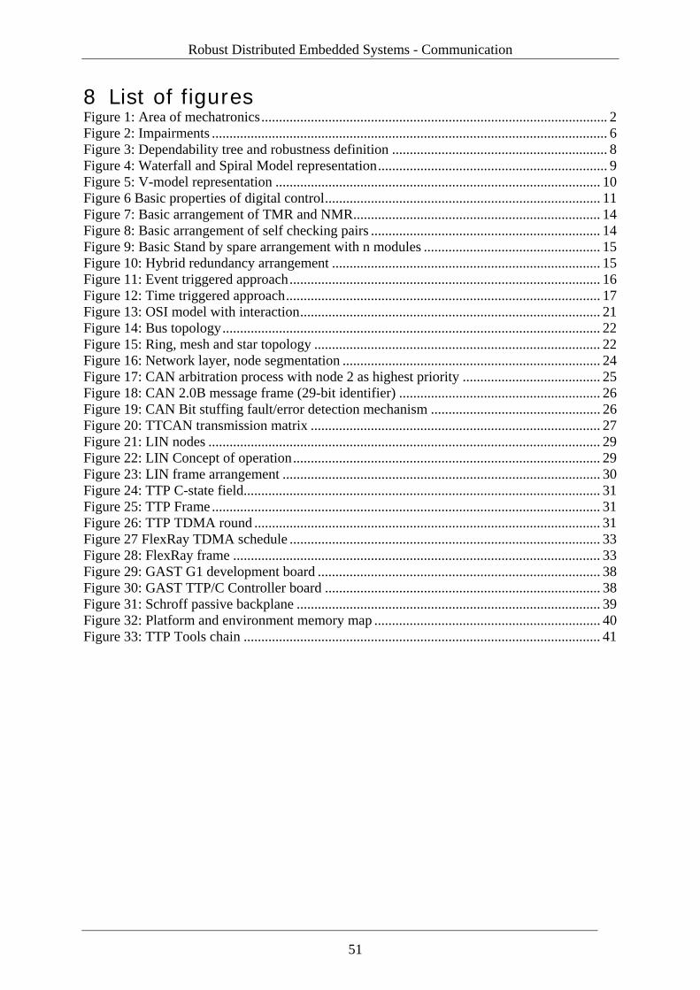
Robust Distributed Embedded Systems - Communication
8 List of figures Figure 1: Area of mechatronics.................................................................................................. 2 Figure 2: Impairments ................................................................................................................ 6 Figure 3: Dependability tree and robustness definition ............................................................. 8 Figure 4: Waterfall and Spiral Model representation................................................................. 9 Figure 5: V-model representation ............................................................................................ 10 Figure 6 Basic properties of digital control.............................................................................. 11 Figure 7: Basic arrangement of TMR and NMR...................................................................... 14 Figure 8: Basic arrangement of self checking pairs ................................................................. 14 Figure 9: Basic Stand by spare arrangement with n modules .................................................. 15 Figure 10: Hybrid redundancy arrangement ............................................................................ 15 Figure 11: Event triggered approach........................................................................................ 16 Figure 12: Time triggered approach......................................................................................... 17 Figure 13: OSI model with interaction..................................................................................... 21 Figure 14: Bus topology........................................................................................................... 22 Figure 15: Ring, mesh and star topology ................................................................................. 22 Figure 16: Network layer, node segmentation ......................................................................... 24 Figure 17: CAN arbitration process with node 2 as highest priority ....................................... 25 Figure 18: CAN 2.0B message frame (29-bit identifier) ......................................................... 26 Figure 19: CAN Bit stuffing fault/error detection mechanism ................................................ 26 Figure 20: TTCAN transmission matrix .................................................................................. 27 Figure 21: LIN nodes ............................................................................................................... 29 Figure 22: LIN Concept of operation....................................................................................... 29 Figure 23: LIN frame arrangement .......................................................................................... 30 Figure 24: TTP C-state field..................................................................................................... 31 Figure 25: TTP Frame .............................................................................................................. 31 Figure 26: TTP TDMA round .................................................................................................. 31 Figure 27 FlexRay TDMA schedule ........................................................................................ 33 Figure 28: FlexRay frame ........................................................................................................ 33 Figure 29: GAST G1 development board ................................................................................ 38 Figure 30: GAST TTP/C Controller board .............................................................................. 38 Figure 31: Schroff passive backplane ...................................................................................... 39 Figure 32: Platform and environment memory map ................................................................ 40 Figure 33: TTP Tools chain ..................................................................................................... 41
51

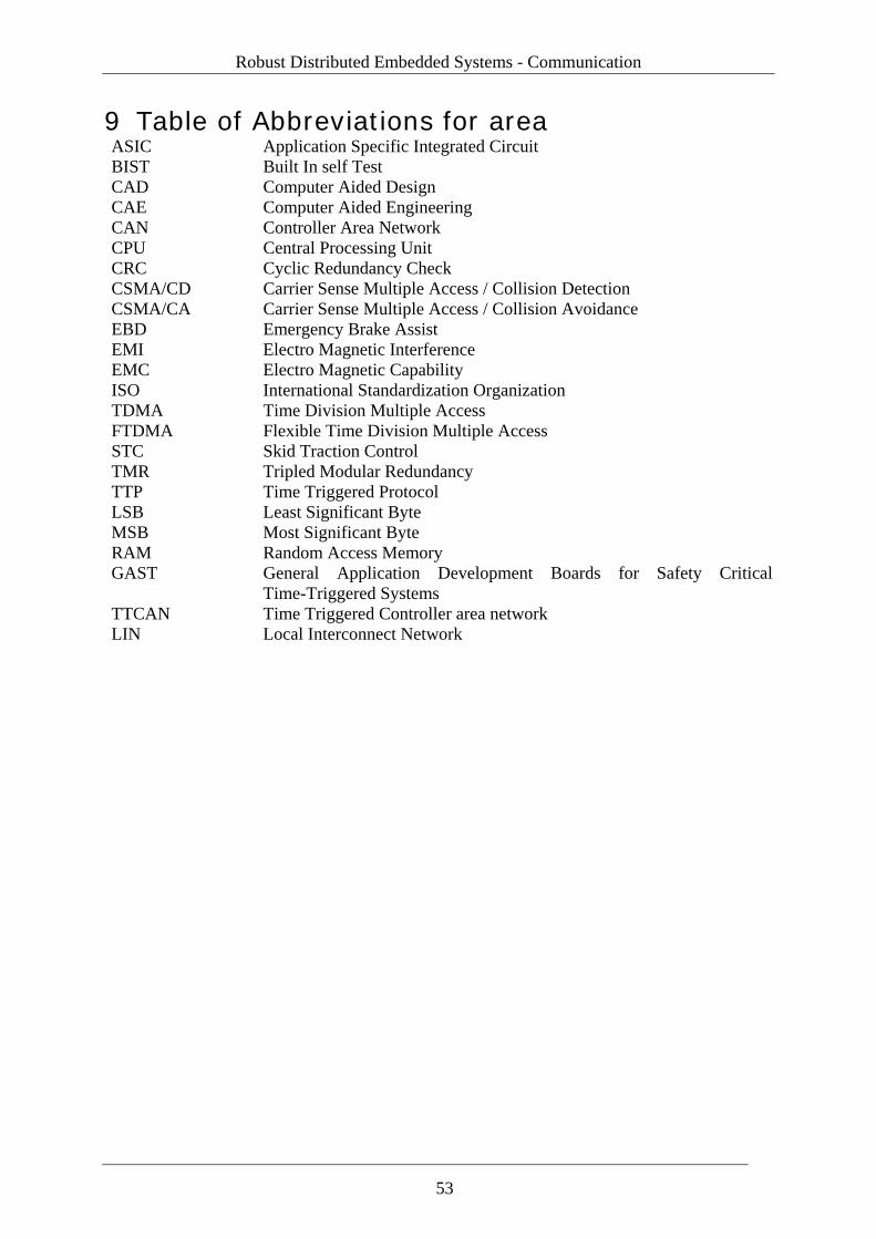
Robust Distributed Embedded Systems - Communication
9 Table of Abbreviations for area ASIC Application Specific Integrated Circuit BIST Built In self Test CAD Computer Aided Design CAE Computer Aided Engineering CAN Controller Area Network CPU Central Processing Unit CRC Cyclic Redundancy Check CSMA/CD Carrier Sense Multiple Access / Collision Detection CSMA/CA Carrier Sense Multiple Access / Collision Avoidance EBD Emergency Brake Assist EMI Electro Magnetic Interference EMC Electro Magnetic Capability ISO International Standardization Organization TDMA Time Division Multiple Access FTDMA Flexible Time Division Multiple Access STC Skid Traction Control TMR Tripled Modular Redundancy TTP Time Triggered Protocol LSB Least Significant Byte MSB Most Significant Byte RAM Random Access Memory GAST General Application Development Boards for Safety Critical
Time-Triggered Systems TTCAN Time Triggered Controller area network LIN Local Interconnect Network
53


