4710 IEEE TRANSACTIONS ON VEHICULAR TECHNOLOGY, VOL. 58, NO. 9, NOVEMBER 2009
Robust Monitoring of an Electric Vehicle WithStructured and Unstructured Uncertainties
Mohand Arab Djeziri, Rochdi Merzouki, and Belkacem Ould Bouamama
Abstract—This paper deals with a robust fault-detection andisolation (FDI) technique, which is applied to the traction system ofan electric vehicle, in the presence of structured and unstructureduncertainties. Due to the structural and multidomain properties ofthe bond graph, the generation of a nonlinear model and residualsfor the studied system with adaptive thresholds is synthesized.The parameters and structured uncertainties are identified byusing a least-square algorithm. A super-twisting observer is usedto estimate both unstructured uncertainties and unknown inputs.Cosimulation with real experimental data shows the robustness ofthe residuals to the considered uncertainties and their sensitivityto the faults.
Index Terms—Analytical redundancy relations (ARRs), bondgraph (BG), electric vehicle, fault detection and isolation (FDI),linear fractional transformations (LFTs), structured and unstruc-tured uncertainties.
I. INTRODUCTION
NOWADAYS, electric vehicles are considered to be sus-tainable systems, which release almost no pollutant gases
and less disturbing noises when they are operated. Due tothe properties of control and monitoring of electric motors,the electric vehicles are often used for applications related tointelligent transport.
During the last decade, many contributions on the field offault detection and isolation (FDI) applied to road vehicles havebeen developed: One can cite [15], where a qualitative model-based approach for fault diagnosis is proposed. It consists ofdeveloping a machine learning technology to detect and isolatemultiple classes of faults in an electric drive. The proposed FDIapproach is robust when the faults are perfectly known, andthe main advantage is that the list of faults can progressivelybe improved after new fault identification. In [16], a diagnosissystem for the air-intake system of a turbo-charged engine isdesigned by a systematic way, where different sensor faults andleakages are considered. This so-called multimodel approachrequires developing a model for almost faulty situations. Thelatter approach becomes difficult to implement in the case of
Manuscript received November 1, 2008; revised February 25, 2009 andJune 5, 2009. First published June 26, 2009; current version publishedNovember 11, 2009. This work was supported in part by the regional projectCampus International sur la Sécurité et l’Intermodalité des Transports (CISIT)and in part by the Centre National de Recherche Scientifique. The review ofthis paper was coordinated by Prof. M. E. Benbouzid.
The authors are with the Laboratoire d’Automatique, Génie Informatique etSignal, UMR-CNRS 8146, Ecole Polytechnique Universitaire de Lille, 59651Villeneuve d’Ascq, France.
Color versions of one or more of the figures in this paper are available onlineat http://ieeexplore.ieee.org.
Digital Object Identifier 10.1109/TVT.2009.2026281
complex and uncertain systems. A motor fault diagnosis ap-proach using a signal-based theory is developed in [11] by usinga wavelet principle, whereas in [5], the frequency spectrum isused to distinguish the fault signal from disturbances. FDI usingobserver and parity space approaches are developed in [7]–[10]for several complex systems with different specifications.
An electric traction system is considered as a mechatronicsystem where several types of energy are involved, such aselectrical, mechanical, and thermal. To model this kind ofsystem, one needs a unified tool such as the bond graph (BG)[10] to represent the involved multiple-energy domains. Fur-thermore, structural properties (observability, monitorability,etc.) of the BG can help generate fault indicators and faultdetection algorithms [1], [2]. The BG tool is also used for themodeling and diagnosis of uncertain systems, where in [17], amodel of uncertain linear systems is developed using two ap-proaches. The first method consider the parameter uncertaintyas a BG element, whereas the second method considers thelinear fractional transformation (LFT) form, which representsthe multiplicative uncertainty on the parameter. In [3] and [4],a BG model based on robust fault diagnosis is developed byconsidering the residual sensitivity analysis.
In the following work, multidomain modeling of tractionactuators for an electric vehicle is presented. Structured andunstructured uncertainties are taken into account in the mod-eling step to generate analytical redundancy relations (ARRs)and adaptive thresholds. The innovative interest of the usedapproach can be summarized in three points.
1) Modeling. The BG tool allows the design of the mul-tidomain model in the LFT form, even on nonlinearsystems, whereas a state model of nonlinear systems isoften difficult to synthesize. The global model can bedesigned in a modular manner by connecting differentsubsystems. Moreover, the LFT model can easily be im-proved by adding uncertain BG elements. Compared withthe classical LFT state model, the LFT BG representationallows explicitly showing the location of the uncertainpart.
2) Diagnosis. Due to the graphical aspect of the BG, ro-bust ARRs and adaptive thresholds can systematically begenerated.
3) Integration. In relation to the cited properties, a diag-nosis algorithm is implemented using an oriented objectapproach.
This paper is organized as follows: Section II deals with thetraction system modeling and monitorability analysis, whereas
DJEZIRI et al.: MONITORING OF ELECTRIC VEHICLE WITH STRUCTURED AND UNSTRUCTURED UNCERTAINTIES 4711
Fig. 1. RobuCar’s electric vehicle.
the BG model in the LFT form for ARR generation is givenin Section III. The generation of robust ARRs is given inSection IV; then, in Section V, the identification method of theparameters and uncertainties is presented. Cosimulation withthe Callas–Prosper software of the dynamic vehicle is given inSection VI.
II. DETERMINIST BG MODEL AND
MONITORABILITY ANALYSIS
This section describes the model of the jth electromechanicaltraction system with attached contact efforts from the studiedRobuCar vehicle of Fig. 1. It is an overactuated electric vehiclewith four actuated traction wheels and two actuated steeringsystems and is composed of the following: 1) 12-V 60-Ahsealed seal batteries; 2) a honeycomb chassis; 3) a front rightwheel; 4) a front control cabinet; 5) a front steering electricaljack; 6) a front left wheel; 7) a rear left wheel; 8) a rear rightwheel; 9) a rear steering electrical jack; and 10) a rear controlcabinet.
The list of the used symbols in the model is given in Table I.
A. Electromechanical Traction System Model
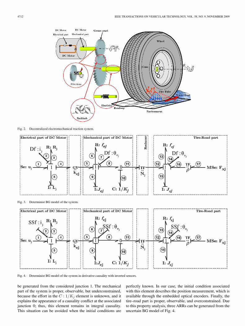
There are six electromechanical systems located on theRobuCar’s vehicle of Fig. 1, and they are used for the tractionand steering motions. They are constituted by three principalcomponents: 1) the dc motor part, which is the combinationof electrical and mechanical parts; 2) the gear system part;and 3) the tire–road part. In this section, dynamic BG modelsof all of these components are graphically synthesized andthen expressed by differential equations. The electromechanicaltraction system for the RobuCar’s vehicle is presented in Fig. 2,where electrical and mechanical domains are interacted.
The BG model of the jth electromechanical system of Robu-Car in integral causality is given in Fig. 3, where j ∈ [1, 6]. Thenonlinearities are defined by the longitudinal contact efforts andact on the tire–road area.
The electrical circuit of the electromechanical system (seeFig. 3) is composed of the input voltage source Se : uj , elec-
TABLE INOMENCLATURES
trical resistance R : Rj , inductance I : Lj , and electromotiveforce (EMF), which is linear to the angular velocity of the rotorwith the EMF constant kej
and modeled by the BG elementGY : kej
. The gyrator element GY describes the power transferfrom the electrical domain to the mechanical domain.
The mechanical part of the jth dc motor is characterized bythe efforts of inertia Jej
· θej, viscous friction fej
· θejof the
transmitted torque Kj · (θej− Nj · θsj
), and the input motortorque Γj , which is a function of the current ij and the torqueconstant kej
. Nj is the constant of the gear transmission.The wheel system represents the load part of the jth electro-
mechanical system, which is characterized by the efforts of theinertia Jsj
· θsj, viscous friction fsj
· θsj, transmitted torque
through the reducer part Nj · Kj · (θej− Nj · θsj
), and longi-tudinal effort contact ρ · Fxj
, where ρ describes the constantwheel radius. Then, the dynamic model of the jth electro-mechanical system is presented in
⎧⎪⎪⎨⎪⎪⎩
Lj · (d/dt) · (ij) = uj − Rj · ij − kej· θej
Jej· θej
= −fej· θej
+ Γj − Kj ·(θej
− Nj · θsj
)Jsj
· θsj= −fsj
· θsj+ Nj .Kj ·
(θej
− Nj · θsj
)− ρ · Fxj
(1)
where θsj, θej
, θsj, and θej
are the accelerations and velocitiesof the jth reducer and motor parts, respectively, which arededuced by derivation of the measured positions θsj
and θej.
Knowing that the introduction of uncertainties does not affectthe causality and the structural properties of the BG elements inthe LFT form [3], the monitorability analysis (i.e., ability togenerate an ARR) is realized using the determinist BG model.The monitorability analysis developed in [4] shows that, in thecase of unknown initial conditions, the system should be proper,observable, and overconstrained to be able to generate an ARR.These properties are recalled in the Appendix.
Monitorability analysis shows that the electrical part of the dcmotor is proper, observable, and overconstrained, because thereis no conflict of causality in this part of the model. The ARR can
4712 IEEE TRANSACTIONS ON VEHICULAR TECHNOLOGY, VOL. 58, NO. 9, NOVEMBER 2009
Fig. 4. Determinist BG model of the system in derivative causality with inverted sensors.
be generated from the considered junction 1. The mechanicalpart of the system is proper, observable, but underconstrained,because the effort in the C : 1/Kj element is unknown, and itexplains the appearance of a causality conflict at the associatedjunction 0; thus, this element remains in integral causality.This situation can be avoided when the initial conditions are
perfectly known. In our case, the initial condition associatedwith this element describes the position measurement, which isavailable through the embedded optical encoders. Finally, thetire–road part is proper, observable, and overconstrained. Dueto this property analysis, three ARRs can be generated from theuncertain BG model of Fig. 4.
DJEZIRI et al.: MONITORING OF ELECTRIC VEHICLE WITH STRUCTURED AND UNSTRUCTURED UNCERTAINTIES 4713
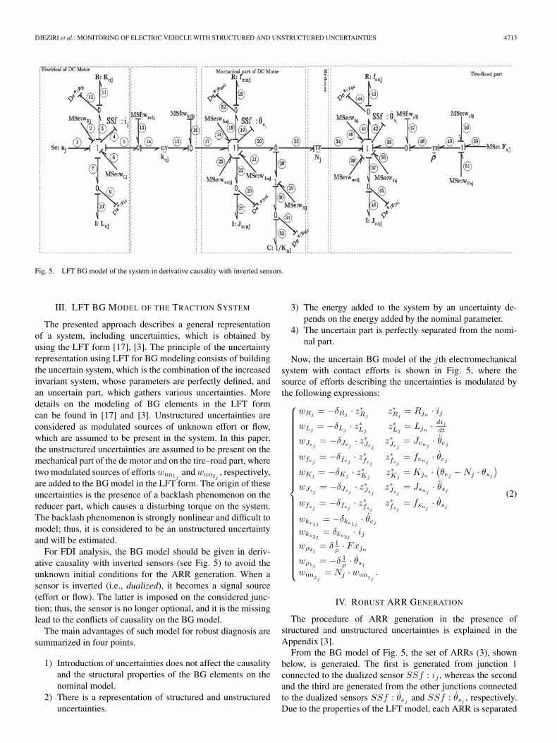
Fig. 5. LFT BG model of the system in derivative causality with inverted sensors.
III. LFT BG MODEL OF THE TRACTION SYSTEM
The presented approach describes a general representationof a system, including uncertainties, which is obtained byusing the LFT form [17], [3]. The principle of the uncertaintyrepresentation using LFT for BG modeling consists of buildingthe uncertain system, which is the combination of the increasedinvariant system, whose parameters are perfectly defined, andan uncertain part, which gathers various uncertainties. Moredetails on the modeling of BG elements in the LFT formcan be found in [17] and [3]. Unstructured uncertainties areconsidered as modulated sources of unknown effort or flow,which are assumed to be present in the system. In this paper,the unstructured uncertainties are assumed to be present on themechanical part of the dc motor and on the tire–road part, wheretwo modulated sources of efforts wun1j
and wun2j, respectively,
are added to the BG model in the LFT form. The origin of theseuncertainties is the presence of a backlash phenomenon on thereducer part, which causes a disturbing torque on the system.The backlash phenomenon is strongly nonlinear and difficult tomodel; thus, it is considered to be an unstructured uncertaintyand will be estimated.
For FDI analysis, the BG model should be given in deriv-ative causality with inverted sensors (see Fig. 5) to avoid theunknown initial conditions for the ARR generation. When asensor is inverted (i.e., dualized), it becomes a signal source(effort or flow). The latter is imposed on the considered junc-tion; thus, the sensor is no longer optional, and it is the missinglead to the conflicts of causality on the BG model.
The main advantages of such model for robust diagnosis aresummarized in four points.
1) Introduction of uncertainties does not affect the causalityand the structural properties of the BG elements on thenominal model.
2) There is a representation of structured and unstructureduncertainties.
3) The energy added to the system by an uncertainty de-pends on the energy added by the nominal parameter.
4) The uncertain part is perfectly separated from the nomi-nal part.
Now, the uncertain BG model of the jth electromechanicalsystem with contact efforts is shown in Fig. 5, where thesource of efforts describing the uncertainties is modulated bythe following expressions:⎧⎪⎪⎪⎪⎪⎪⎪⎪⎪⎪⎪⎪⎪⎪⎪⎪⎪⎪⎪⎪⎪⎪⎪⎪⎪⎨
⎪⎪⎪⎪⎪⎪⎪⎪⎪⎪⎪⎪⎪⎪⎪⎪⎪⎪⎪⎪⎪⎪⎪⎪⎪⎩
wRj= −δRj
· z∗Rjz∗Rj
= Rjn· ij
wLj= −δLj
· z∗Ljz∗Lj
= Ljn· dij
dt
wJej= −δJej
· z∗Jejz∗Jej
= Jenj· θej
wfej= −δfej
· z∗fejz∗fej
= fenj· θej
wKj= −δKj
· z∗Kjz∗Kj
= Kjn·(θej
− Nj · θsj
)wJsj
= −δJsj· z∗Jsj
z∗Jsj= Jsnj
· θsj
wfsj= −δfsj
· z∗fsjz∗fsj
= fsnj· θsj
wke1j= −δke1j
· θej
wke2j= δke2j
· ijwρ2j
= δ 1ρ · Fxjn
wρ1j= −δ 1
ρ · θsj
wun2j= Nj · wun1j
.
(2)
IV. ROBUST ARR GENERATION
The procedure of ARR generation in the presence ofstructured and unstructured uncertainties is explained in theAppendix [3].
From the BG model of Fig. 5, the set of ARRs (3), shownbelow, is generated. The first is generated from junction 1connected to the dualized sensor SSf : ij , whereas the secondand the third are generated from the other junctions connectedto the dualized sensors SSf : θej
and SSf : θsj, respectively.
Due to the properties of the LFT model, each ARR is separated
4714 IEEE TRANSACTIONS ON VEHICULAR TECHNOLOGY, VOL. 58, NO. 9, NOVEMBER 2009
into two distinguished parts, as given in (4)–(6), shown below.Thus⎧⎪⎪⎪⎪⎪⎪⎪⎪⎪⎪⎪⎪⎪⎪⎪⎨
⎪⎪⎪⎪⎪⎪⎪⎪⎪⎪⎪⎪⎪⎪⎪⎩
ARR1j: uj − Ljn
· (d/dt) · (ij) − Rjn· ij
− kej·(θej
− wke2j
)+ wRj
+ wLj+ wun1j
= 0
ARR2j: kenj
·(ij + wke1j
)− Jenj
· θej− fenj
· θej
− wun2j− Kn
j·(θej
− Nj · θsj
)+ wJej
+ wfej+ wKj
= 0
ARR3j: Nj · wun2j
− Jsnj· θsj
− fsnj· θsj
+ Nj · Knj·(θej
− Nj · θsj
)− ρn · Fxnj
− ρn · wρ + wJsj+ wfsj
+ wKj+ wFxj
= 0
(3)
{r1j
= uj − Lj · (d/dt) · (ij) − Rj · ij − kej· θej
a1j=
∣∣wRj
∣∣ +∣∣wLj
∣∣ + kej·∣∣∣wke2j
∣∣∣ +∣∣∣wun1j
∣∣∣ (4)
⎧⎪⎪⎨⎪⎪⎩
r2j= kenj
· ij − Jej· θej
− fej· θej
− wun2j
− Kj ·(θej
− Nj · θsj
)a2j
=∣∣∣wJej
∣∣∣ +∣∣∣wfej
∣∣∣ +∣∣wKj
∣∣ + kenj·∣∣∣wke1j
∣∣∣(5)
⎧⎪⎪⎨⎪⎪⎩
r3j= Nj · wun2j
− Jsj· θsj
− fsj· θsj
+ Nj · Kj ·(θej
− Nj · θsj
)− ρ · Fxj
a3j=
∣∣∣wJsj
∣∣∣ +∣∣∣wfsj
∣∣∣ +∣∣wKj
∣∣ +∣∣∣wFxj
∣∣∣ + ρn · |wρ| .(6)
By replacing the residual rj and the uncertain part of (4)–(6)in the ARR of (3), we obtain
rj +∑
wij= 0 ⇒ rj = −
∑wij
. (7)
By using the following properties, i.e., |∑
wij| �
∑|wij
|and −
∑|wij
| � |∑
wij| �
∑|wij
|, an upper threshold,called aj , is generated such that
rj � aj with aj =∑ ∣∣wij
∣∣ . (8)
Structured and unstructured uncertainties can be constant orvariable, and their variation can be positive or negative withbounded values. Since the variation of the residual follows thevariation of the uncertainties without a fault, it can vary in thepositive and negative directions, and a lower threshold, called−aj , is generated. Thus, the generated thresholds constitute anenvelope of the residual in normal operation, i.e.,
−aj � rj � aj . (9)
V. IDENTIFICATION OF PARAMETERS AND UNCERTAINTIES
Structured and unstructured uncertainties are separately iden-tified by two methods. This choice of identification gives riseto an overevaluation of both structured and unstructured uncer-tainties. Consequently, the generated thresholds in the diagnosispart will also be overevaluated to avoid false alarms.
A. Structured Uncertainty Identification
The nominal values of parameters and uncertainties are iden-tified after raising the vehicle from the road. The determinist
model of the traction system is given in (1). This model can bewritten in the following linear parameter form:
Υ = Ψ · Θ (10)
with
Υ =
⎡⎣ uj
Uj
Fxj
⎤⎦
Ψ =
⎡⎣
dij
dt ij θej0 0 0 0 0
0 0 0 θejθej
Ξ1 0 00 0 0 0 0 Nj · Ξ Ξ2 Ξ3
⎤⎦
with
Ξ1 = θej− Nj · θsj
Ξ2 = −ρ−1 · θsjΞ3 = −ρ−1 · θsj
Θ = [Lj Rj kejJej
fejKj Jsj
fsj]T .
For a linear configuration of (10), several methods for pa-rameter identification, such as the recursive least-square andgradient methods [6], exist in the literature. In this paper, thenormalized gradient algorithm of (11) is used, which is betterin the case where the gain adaptation is not perfect, and the nor-malization term ensures the convergence of the identificationalgorithm, i.e.,
Θk = Θk−1 + Te ·Λ · ΨT
k · εk
1 + Λ · ΨTk · εk
(11)
where Θk is the estimation of the parameters Θ at time k,whereas Θk−1 is the parameter estimation at time k − 1, Te
is the sampling time, Λ is the adaptation gain vector, andεk = Υk − Υk is the estimation error of the inputs at time k.
The additive uncertainty on each parameter is considered asthe difference between the maximum value of the parameterand its mean value. Thus, the additive uncertainties are re-lated to their multiplicative values according to the followingrelations:
δR =ΔR
Rn, δ 1
R=
ΔR
Rn + ΔR, δI =
ΔI
In
δC =ΔC
Cn, δTF =
ΔT
Tn, δGY =
ΔG
Gn
where ΔR, ΔI , and ΔC are the additive uncertainty values ofthe BG elements R, I , and C, respectively. ΔT and ΔG are theadditive uncertainty values of TF and GY moduli, respectively.δR, δI , δC , δTF , and δGY are the multiplicative uncertaintiesof the BG elements. Rn, In, Cn, Tn, and Gn are the nominalvalues of the BG elements. δ1/R is the multiplicative uncer-tainty value on the characteristic functions of the R element inconductance causality.
The uncertainty on the wheel radius is experimentally iden-tified, where its nominal value ρn of the radius ρ is identifiedwithout the presence of external load on the vehicle, and thetire is inflated at the maximum level of pressure (2 bar). Theminimum value of the radius ρmin is identified with the limitof external load (350 kg) on the vehicle. Then, the additive
DJEZIRI et al.: MONITORING OF ELECTRIC VEHICLE WITH STRUCTURED AND UNSTRUCTURED UNCERTAINTIES 4715
TABLE IIPARAMETER AND UNCERTAINTY VALUES
and multiplicative uncertainties Δρ and δρ are calculated asfollows:
Δρ = ρn − ρmin, δρ =Δρ
ρn. (12)
The set of parameters and uncertainties of the jth system isgiven in Table II.
The tire–road system is an important and complex part of theoveractuated electric vehicle due to the interaction of severalphenomena (i.e., mechanical, thermal, hydrodynamic, etc.). Inthis paper, only the longitudinal effort is considered accordingto some specifications.
1) The road is uniform and dry.2) The vehicle is light (350 kg).3) The velocity motion is low and constant at steady state
(�12 km/h).4) The vehicle trajectory is straight linear and longitudinal.Several mathematical and experimental models have been
developed for estimation of tire–road unknown inputs, whichdescribe the tire forces generated at conditions of braking,driving, or cornering, such as in [19]. In this paper, a super-twisting observer is used to simultaneously estimate un-structured uncertainties and unknown inputs [14], where thedisturbing torque through the dead zone is considered as theunstructured uncertainty, and the impact effort is considered asthe unknown input.
B. Unstructured Uncertainty Identification
1) State Reconstruction: Let us define the transmittedtorque in the presence of the disturbing torque wun1 for eachjth actuator as follows:
Cj = wun1j+ Kj ·
(θej
− Nj · θsj
). (13)
By considering the presence of the disturbing torque wun1,and by doing the following state variable replacement, i.e.,x1ej
= θej, x1sj
= θsj, x2ej
= θej, and x2sj
= θsj, with j ∈
[1, 6], the system of equations (1) can be written as follows:⎧⎪⎪⎨⎪⎪⎩
x1ej= x2ej
x1sj= x2sj
x2ej= −J−1
ej· fej
· x2ej+ J−1
ej· Γj − J−1
ej· Cj
x2sj= −J−1
sj· fsj
· x2sj+ J−1
sj· Nj · Cj − J−1
sj· ρ · Fxj .
(14)
The observer structure is synthesized as follows:
⎧⎪⎪⎪⎪⎪⎪⎪⎪⎨⎪⎪⎪⎪⎪⎪⎪⎪⎩
˙x1ej= x2ej
+ λ1j·∣∣∣x1ej
−x1ej
∣∣∣ 12 · sign
(x1ej
−x1ej
)˙x1sj
= x2sj+λ1j
·∣∣∣x1sj
−x1sj
∣∣∣ 12 · sign
(x1sj
−x1sj
)˙x2ej
=−J−1ej
· fej· x2ej
+J−1ej
· Γj +α1j· sign
(x1ej
−x1ej
)˙x2sj
=−J−1sj
· fsj· x2sj
+α2j· sign
(x1sj
−x1sj
).
(15)
The state observation error is given in the following systemof equations:
⎧⎪⎪⎪⎪⎪⎪⎪⎪⎪⎪⎪⎨⎪⎪⎪⎪⎪⎪⎪⎪⎪⎪⎪⎩
˙x1ej= x2ej
− λ1j·∣∣∣x1ej
∣∣∣ 12 · sign
(x1ej
)˙x1sj
= x2sj− λ1j
·∣∣∣x1sj
∣∣∣ 12 · sign
(x1sj
)˙x2ej
= −J−1ej
· fej· x2ej
− J−1ej
· Cj − α1j· sign
(x1ej
)˙x2sj
= −J−1sj
· fsj· x2sj
+ J−1sj
· Nj · Cj − J−1sj
· ρ · Fxj
− α2j· sign
(x1sj
).
(16)
In this case, finite-time convergence of the estimated statesto the real state values is obtained, and the convergence proof isgiven in [14].
2) Estimation of the Unknown Input and the UnstructuredUncertainty: Both the longitudinal impact effort Fxj andthe unstructured uncertainty of the disturbing backlash torquewun1j
are considered as unknown inputs and are automaticallyestimated from the observer of (16). Finite-time convergenceof x1ej
, x1sj, x2ej
, and x2sjallows writing of the following
system of equations from (13) and (16):
⎧⎨⎩
J−1ej
· Cj = −α1j· sign
(x1ej
)J−1
sj· ρ · Fxj = −α1j
· sign(x1ej
)− α2j
· sign(x1sj
).
(17)
The value of the unstructured uncertainty wun1jis considered
as the maximum value of the disturbing torque. The minimumvalue Fxjmin of the force Fxj is identified without load on thevehicle, and the tire is inflated at the maximum level of pressure(2 bar). The nominal value of the force Fxjn
is identifiedwhen the vehicle is loaded. Then, additive and multiplicativeuncertainties ΔFxj and δFxj
, respectively, are calculated asfollows:
ΔFxj = Fxjn− Fxj min, δFx =
ΔFxj
Fxjn
. (18)
To show the convergence of the observer, we applied acontrol torque of Fig. 6 on the rear left traction system in contactwith ground, where successively accelerated, uniform, and de-celerated motions in bidirectional ways are simulated, allowingthe bidirectional representation of the canonical contact effortas a function of the velocity of Fig. 7.
4716 IEEE TRANSACTIONS ON VEHICULAR TECHNOLOGY, VOL. 58, NO. 9, NOVEMBER 2009
Fig. 6. Applied control torque for the electromechanical system.
Fig. 7. Estimated effort force.
VI. COSIMULATION RESULTS
RobuCar’s technical characteristics are given in the list thatfollows.
2) Weight:a) About 350 kg, including batteries.b) Velocity: 18 km/h, equivalent to 5 m/s.
3) Batteries:a) 8× 12-V 60-Ah sealed lead batteries.b) Power supply: 24 V.
4) Motors:a) 4 × 900 W, with a switched motor of 24 V.b) 2300 r/min primary, 230 r/min output.c) Inductance L = 0.075 H.d) Resistance R = 0.32 Ω.
5) Instrumentation:a) Six optical encoders < 1 mm, four for direction and
two for steering.
The results that will be presented are obtained after dataacquisition in normal operation. Then, these data are coupledwith a dynamic simulator (CALLAS) [20] to be cosimulated
Fig. 8. Residuals and adaptive thresholds without a fault.
Fig. 9. Residuals and adaptive thresholds with a fault in the electrical resis-tance R.
with the studied traction actuator model. To show fault accuracydetection and isolation with the presence of uncertainties andthe sensitivity to faults, the following scenario is proposed.
1) residual generation in normal operation;2) residual generation in the presence of a fault on the elec-
trical resistance of the dc motor for the traction system;3) residual generation in the presence of a fault on the
mechanical part of the dc motor for the traction system;4) residual generation in the presence of the tire-puncture
fault.
Fig. 8 shows the residuals and adaptive thresholds undernormal operation for the rear left traction system. The residualsare inside the thresholds because there is no fault on the system;thus, no alarm is generated.
The profile of the first introduced fault is given in Fig. 9(a),which describes the progressive variation of the electrical resis-tance R of the dc motor from its nominal value. The reactionof the residuals is shown in Fig. 9(b)–(d). The fault appears attime t = 50 s and is detected at time t = 58 s by the residual r1
DJEZIRI et al.: MONITORING OF ELECTRIC VEHICLE WITH STRUCTURED AND UNSTRUCTURED UNCERTAINTIES 4717
Fig. 10. Vehicle trajectory in the presence of a fault in the electricalresistance R.
Fig. 11. Residuals and adaptive thresholds in the presence of an external fault(a tire puncture or an obstacle on the wheel trajectory).
when the fault value reaches the value of 0.1 Ω. The residualsr2 and r3 are not sensitive to this fault, and they remain insidethe thresholds.
The vehicle trajectory in the presence of the first fault is givenin Fig. 10, where the appearance of the fault causes a vehicle todeviate from the desired trajectory.
The second fault represents an unknown external perturba-tion on the tire, which can be explained by the tire punctureor a static obstacle on the wheel trajectory. This fault causes avariation of the tire velocity at time t = 50 s [see Fig. 11(a)].The reaction of the residuals is given in Fig. 11(b)–(d). Thefault is detected at time t = 51 s by the residual r3, whereasthe residuals r1 and r2 are not sensitive to the introduced fault;thus, they remain inside the thresholds. The presence of thisfault causes a vehicle deviation from the desired trajectory, asshown in Fig. 12.
The third fault is introduced at the level of the mechanicalpart of the dc motor, and it represents a variation of the viscousfriction parameter fe from its nominal value [see Fig. 13(a)].The progressive fault is introduced at time t = 50 s, and it isdetected at time t = 58 s by the residual r1 [see Fig. 11(b)]
Fig. 12. Vehicle trajectory in the presence of an external fault (a tire punctureor an obstacle on the wheel trajectory).
Fig. 13. Residuals and adaptive thresholds in the presence of a fault in themechanical part of the dc motor.
after reaching the fault value of 0.08 N · m · s/rad. The residualr2 is sensitive to this fault at time t = 68 s with a fault valuethat is equal to 0.11 N · m · s/rad. Finally, the residual r3 is lesssensitive to this fault; thus, it remains inside the thresholds. Thepresence of this fault also causes a vehicle to deviate from thedesired trajectory, as shown in Fig. 14.
VII. CONCLUSION
LFT modeling and robust fault diagnosis of a traction sys-tem for an electric vehicle have been presented in this paper.The multidomain aspect of the BG tool was used to modelthe interaction of several physical phenomena. Causal andstructural properties of this graphical tool were used for ARRand adaptive threshold generations. The uncertainties explicitlyappeared on the BG model in the LFT form, and unstructuredparameters and the unknown input were estimated using anonlinear observer. Cosimulation with experiment data showsthe robustness of the residuals to structured and unstructureduncertainties, with sensitivity to the system faults.
4718 IEEE TRANSACTIONS ON VEHICULAR TECHNOLOGY, VOL. 58, NO. 9, NOVEMBER 2009
Fig. 14. Vehicle trajectory in the presence of a fault in the mechanical part ofthe dc motor.
APPENDIX
A. Monitorability Analysis
Definition 1: A BG model is proper if and only if it doesnot contain dynamic elements in derivative causality when themodel is in the preferred integral causality [18] and vice versa.
Definition 2: A BG model is structurally observable if andonly if two conditions are satisfied.
1) On the BG model in integral causality, there exists acausal path between all the dynamic elements I and Cand the detectors De or Df .
2) All the dynamic elements I and C admit derivative cau-sality when the BG model is in the preferred derivativecausality. If some dynamic elements remain in integralcausality, the dualization of the detectors De and Dfmust allow them to be put in derivative causality [18].
Definition 3: When the BG model is in derivative causality,the system is considered overconstrained if and only if, afterdualizing the sensors (effort and flow detectors De and Dfbecome signal sources SSe and SSf ), the elements I and Ccan stay in derivative causality [4].
For the monitoring step, the BG model of system 2 ispresented in derivative causality with inverted sensors, as givenin Fig. 4, because some initial conditions are unknown.
B. ARR Generation
The procedure of ARR generation in the presence of struc-tured and unstructured uncertainties is explained in threesteps [3].
1) The BG model should be written in the preferred deriva-tive causality after dualization of the sensors.
2) From junctions 0 and 1 of an overconstrained part, theARR is deduced by expressing the energetic assessmenton the junction.
3) The obtained ARR consists of two perfectly separatedparts: 1) a nominal part, called rj , which describes thedeterministic system part; and 2) the uncertain part aj ,
which is used for the generation of adaptive thresholdsduring normal operation.
REFERENCES
[1] B. Ould Bouamama, K. Samantaray, M. Staroswiecki, and G. Dauphin-Tanguy, “Derivation of constraint relations from bond graph models forfault detection and isolation,” in Proc. ICBGM, 2003, vol. 35, pp. 04–09.No. 2.
[2] G. Dauphin-Tanguy, A. Rahmani, and C. Sueur, “Bond graph aided designof controlled systems,” Simul. Pract. Theory, vol. 7, no. 5/6, pp. 493–513,Dec. 1999.
[3] M. A. Djeziri, “Diagnostic des Systèmes Incertains par l’Approche BondGraph,” Ph.D. dissertation, EC-Lille Polytech-Lille, Villeneuve-d’Ascq,France, Dec. 2007. N0 d’ordre 63.
[4] M. A. Djeziri, R. Merzouki, B. Ould-Bouamama, andG. Dauphin-Tanguy, “Robust fault diagnosis by using bond graphapproach,” IEEE/ASME Trans. Mechatron., vol. 12, no. 6, pp. 599–611,Dec. 2007.
[5] B. Dubuisson, Automatique et Statistiques Pour le Diagnostic, vol. 1.Paris, France: Hermès, 2001, p. 204.
[6] D. Landau, Identification des Systèmes’. Paris, France: Hermes, 1998.[7] M. L Luschen, “Derivation and application of nonlinear analytical redun-
dancy techniques with applications to robotics,” Ph.D. dissertation, RiceUniv., Houston, TX, 2001.
[8] P. M. Frank, “Fault diagnosis in dynamic systems using analyticaland knowledge-based redundancy—A survey and some new results,”Automatica, vol. 26, no. 3, pp. 459–474, May 1990.
[9] P. M. Frank and X. Ding, “Survey of robust residual generation andevaluation methods in observer-based fault detection systems,” J. ProcessControl, vol. 7, no. 6, pp. 403–424, 1997.
[10] D. C. Karnopp, D. Margolis, and R. Rosenberg, Systems Dynamics:A Unified Approach, 2nd ed. New York: Wiley, 1990.
[11] K. Kim and A. G. Parlos, “Induction motor fault diagnosis based onneuropredictors and wavelet signal processing,” IEEE/ASME Trans.Mechatron., vol. 7, no. 2, pp. 201–219, Jun. 2002.
[12] P. Mhaskar, C. McFall, A. Gani, P. D. Christofides, and J. F. Davis, “Iso-lation and handling of actuator faults in nonlinear systems,” Automatica,vol. 44, no. 1, pp. 53–62, Jan. 2008.
[13] R. Merzouki, B. Ould-Bouamama, M. A. Djeziri, and M. Bouteldja,“Modelling and estimation for tire–road system using bond graphapproach,” Mechatron., vol. 17, no. 2/3, pp. 93–108, Mar./Apr. 2007.
[14] R. Merzouki and J. C. Cadiou, “Estimation of backlash phenomenon in theelectromechanical actuator,” Control Eng. Pract., vol. 13, no. 8, pp. 973–983, Aug. 2005.
[15] Y. L. Murphey and M. Abul Masrur, “Model-based fault diagnosis inelectric drives using machine learning,” IEEE/ASME Trans. Mechatron.,vol. 11, no. 3, pp. 290–303, Jun. 2006.
[16] M. Nyberg, “Model-based diagnosis of an automotive engine using sev-eral types of fault models,” IEEE Trans. Control Syst. Technol., vol. 10,no. 5, pp. 679–689, Sep. 2002.
[17] C. Siè Kam, “Les Bond Graphs pour la Modèlisation des SystèmesLinèaires Incertains,” Ph.D. dissertation, USTLille1-ECLille, Villeneuve-d’Ascq, France, Dec. 2001. N0 d’ordre 3065.
[18] C. Sueur and G. Dauphin-Tanguy, “Structural controllability and observ-ability of linear systems represented by bond graphs,” J. Franklin Inst.,vol. 326, pp. 869–883, 1989.
[19] H. B. Pacejka, Tyre and Vehicle Dynamics. Amsterdam,The Netherlands: Elsevier, 2006.
[20] Website of Dynamic Virtual Simulator CALLAS. [Online]. Available:http://www.callasprosper.com
Mohand Arab Djeziri received the automatic engi-neer degree from the University of Tizi-Ouzou,Tizi-Ouzou, Algeria, in 2003. He is currently work-ing toward the Ph.D. degree with the Ecole Poly-technique Universitaire de Lille, Villeneuve d’Ascq,France.
His research field concerns robust diagnosis ofcomplex systems applied for mechatronics and in-dustrial processes. He is the author of several papersin this field.
DJEZIRI et al.: MONITORING OF ELECTRIC VEHICLE WITH STRUCTURED AND UNSTRUCTURED UNCERTAINTIES 4719
Rochdi Merzouki received the electrical engineerdegree from the University of Batna, Batna, Algeria,in 1996 and the Ph.D. degree in robotics and automa-tion from the University of Versailles, Versailles,France, in 2002.
He is currently an Associate Professor with theEcole Polytechnique Universitaire de Lille, Vil-leneuve d’Ascq, France. His main research areasconcern modeling, fault diagnosis, and fault-tolerantcontrol for mechatronics systems applied to roboticsand transportation fields.
Belkacem Ould Bouamama received the auto-matic engineer degree from the Institut National desHydrocarbures et de la Chimie INHC Boumerdes,Algeria, in 1982 and the Ph.D. degree from theAcadémie pétrole and gaz “Goubkine,” Moscow,Russia, in 2002.
He is a Full Professor with the Ecole Poly-technique Universitaire de Lille, Villeneuve d’Ascq,France. His main research areas concern integrateddesign for supervision of system engineering usingbond graphs. Their application domains are mainly
nuclear, petrochemical, and mechatronic systems. He is the author of severalinternational publications in these domains and the coauthor of three booksabout bond graph modeling and the fault detection and isolation area.