160
Rockaway NJ USA 07886 www.btechinc.com Battery Validation Manager – Software and Battery Validation System Operating Manual

Rockaway NJ USA 07886 www.btechinc.com
Battery Validation Manager – Software and Battery Validation System
Operating Manual


Safety Information
Exceptasexplainedinthismanual,donotattempttoserviceBTECHequipmentyourself.Openingtheequipmentmayexposeyoutodangerousvoltages.Referservicingbeyondthatdescribedinthismanualtoauthorizedpersonnel.
Donotallowliquidsormoisturetogetintotheequipment.Ifliquiddoesgetintotheequipment,unplugitimmediatelyandcontactyournearestauthorizedservicecenterorBTECHdirectly.
Ensureequipmentisprovidedadequateventilation.Donotblockequipmentventilationopenings.
Donotexceedequipmentvoltageorpowerratingsandcapabilities.
Makesurethatequipmentisproperlygrounded.
Donotletunauthorizedpersonsoperatetheequipment.
Donotenergizethecabinetoranycomponentwith115VACorbatteryvoltageuntilaftertheinstallationiscomplete.
Useofthisproductinamannernotspecifiedcouldcompromisethedesigned‐insafetyofthisproduct.
WARNING!TheBatteryValidationSystemisdesignedtoconnecttoUPSsystemsthatare600VDCorlessandamaximumof300Vwithrespecttoearthground.Thevoltagewithrespecttoearthgroundmustbeverifiedbeforeconnectingthesystem.Thiscanbedonebymeasuringthevoltagefromeachbatterypostreferencedtoearthground.Thevoltagecannotexceed300V.
WARNING!HighVoltageorcurrentmaybepresentintheequipment.Onlyqualifiedpersonnelshouldperformtheoperationsdescribedinthismanual.
WARNING!HighVoltagesexistinsidethesystemcomponentsandontheequipmentterminals.Calibrationmustbeperformedonlybytechnicallyqualifiedpersons.Observeelectricalsafetyprecautionswhenremovingandinstallingequipmentcovers,andwhenconnectingleadsandmakingadjustments.
WARNING!Fusescannotbechangedbytheoperator.
WARNING!OnlyusetheACpowercordprovidedwiththesystem.Substitutingthiscordmaycausedamagetothesystemandplacepersonnelatriskelectricshock.

Technical Specifications
SCM‐600 ACInput Models S5x‐xxxxxx‐xx‐xx‐A0
S5x‐xxxxxx‐xx‐xx‐A1 Voltage 90–125 VAC US,CAN,&JPN
100–240 VAC Europe,Korea Power Maximum 75 Watts Frequency 50‐60 Hz DCInput Models S5x‐xxxxxx‐xx‐xx‐D2
S5x‐xxxxxx‐xx‐xx‐D3Voltage Nominal48VDC 26‐60 VDC
Nominal120VDC
95‐145 VDC
Power Maximum 75 Watts OperatingEnvironment
TemperatureRange 41–104 °F 5–40°C
Humidity 0%to80%RH(32–86°F) 0–30°C0%to50%RH(88–104°F)
31–40°C
Altitude 0–2000 m Mechanical Length 16.875 ins (429mm) Width 16.5625 ins (421mm) Depth 3.5 ins (89mm) Weight 24 lbs (10.9kg)

S5OperatingManual
Technical Specifications
Ver.2.0(Aug.2012) P a g e |i
BTECHInc.takesprideinthequalityofitsnewdocumentation.However,technicalinaccuracies,typographicalerrorsandeditorialomissionsdooccurfromtimetotime.Althoughthedocumentationisprovided“asis,”andBTECHInc.disclaimsalldirect,indirect,orconsequentialdamagesthatmayresultfromsucherrors,pleaseletBTECHInc.knowimmediatelyifyoudiscoverinaccuracies,errors,oromissions.Wewillmakeeveryefforttocorrectthedeficienciesinneweditionsandupdates.
Copyright2012byBTECHInc.
AllRightsreserved
10AstroPlace
Rockaway,NJ07866
M7.5‐2
Ver.2.0(August2012)
PrintedintheUnitedStatesofAmerica
BTECH SERVICE AND SUPPORT
Phone:1‐973‐983‐1120
Fax:1‐973‐983‐1125
E‐mail:[email protected]
Webpage:http://www.btechinc.com
This product has been tested to the requirements of CAN/CSA-C22.2 No. 61010-1, second edition, including Amendment 1, or a later version of the same standard incorporating the same level of testing requirements.
This Class A digital apparatus complies with Canadian ICES-003. Cet appareil numérique de la classe A est conforme à la norme NMB-003 du Canada.
This device complies with part 15 of the FCC Rules. Operation is subject to the following two conditions: (1) This device may not cause harmful interference, and, (2) this device must accept any interference received, including interference that may cause undesired operation.
Cautiontouser:Changesormodificationsnotexpresslyapprovedbythepartyresponsibleforcompliancecouldvoidtheuser'sauthoritytooperatetheequipment
Note:ThisequipmenthasbeentestedandfoundtocomplywiththelimitsforaClassAdigitaldevice,pursuanttopart15oftheFCCRules.Theselimitsaredesignedtoprovidereasonableprotectionagainstharmfulinterferencewhentheequipmentisoperatedinacommercialenvironment.Thisequipmentgenerates,uses,andcanradiateradiofrequencyenergyand,ifnotinstalledandusedinaccordancewiththeinstructionmanual,maycauseharmfulinterferencetoradiocommunications.Operationofthisequipmentinaresidentialareaislikelytocauseharmful

S5OperatingManual
Technical Specifications
Ver.2.0(Aug.2012) P a g e |ii
interferenceinwhichcasetheuserwillberequiredtocorrecttheinterferenceathisownexpense.
S5OperatingManual
Table of Contents
Ver.2.0(Aug.2012) P a g e |iii
Table of Contents
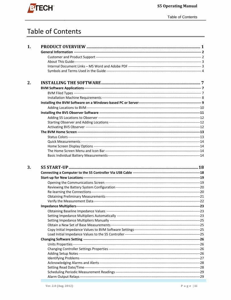
1. PRODUCTOVERVIEW.............................................................................................................1 General Information ‐‐‐‐‐‐‐‐‐‐‐‐‐‐‐‐‐‐‐‐‐‐‐‐‐‐‐‐‐‐‐‐‐‐‐‐‐‐‐‐‐‐‐‐‐‐‐‐‐‐‐‐‐‐‐‐‐‐‐‐‐‐‐‐‐‐‐‐‐‐‐‐‐‐‐‐‐‐‐‐‐‐‐‐‐‐‐‐‐‐‐‐‐‐‐‐‐‐‐‐‐‐‐‐‐‐‐‐‐‐ 2
Customer and Product Support ‐‐‐‐‐‐‐‐‐‐‐‐‐‐‐‐‐‐‐‐‐‐‐‐‐‐‐‐‐‐‐‐‐‐‐‐‐‐‐‐‐‐‐‐‐‐‐‐‐‐‐‐‐‐‐‐‐‐‐‐‐‐‐‐‐‐‐‐‐‐‐‐‐‐‐‐‐‐‐‐‐‐‐‐‐‐‐‐‐‐‐ 2 About This Guide‐‐‐‐‐‐‐‐‐‐‐‐‐‐‐‐‐‐‐‐‐‐‐‐‐‐‐‐‐‐‐‐‐‐‐‐‐‐‐‐‐‐‐‐‐‐‐‐‐‐‐‐‐‐‐‐‐‐‐‐‐‐‐‐‐‐‐‐‐‐‐‐‐‐‐‐‐‐‐‐‐‐‐‐‐‐‐‐‐‐‐‐‐‐‐‐‐‐‐‐‐‐‐‐‐‐‐‐‐‐ 3 Internal Document Links – MS Word and Adobe PDF ‐‐‐‐‐‐‐‐‐‐‐‐‐‐‐‐‐‐‐‐‐‐‐‐‐‐‐‐‐‐‐‐‐‐‐‐‐‐‐‐‐‐‐‐‐‐‐‐‐‐‐‐‐‐‐‐‐‐‐‐‐‐‐ 3 Symbols and Terms Used in the Guide ‐‐‐‐‐‐‐‐‐‐‐‐‐‐‐‐‐‐‐‐‐‐‐‐‐‐‐‐‐‐‐‐‐‐‐‐‐‐‐‐‐‐‐‐‐‐‐‐‐‐‐‐‐‐‐‐‐‐‐‐‐‐‐‐‐‐‐‐‐‐‐‐‐‐‐‐‐‐‐‐‐‐ 4
2. INSTALLINGTHESOFTWARE...............................................................................................7 BVM Software Applications ‐‐‐‐‐‐‐‐‐‐‐‐‐‐‐‐‐‐‐‐‐‐‐‐‐‐‐‐‐‐‐‐‐‐‐‐‐‐‐‐‐‐‐‐‐‐‐‐‐‐‐‐‐‐‐‐‐‐‐‐‐‐‐‐‐‐‐‐‐‐‐‐‐‐‐‐‐‐‐‐‐‐‐‐‐‐‐‐‐‐‐‐‐‐‐‐‐‐‐‐‐ 7
BVM Filed Types ‐‐‐‐‐‐‐‐‐‐‐‐‐‐‐‐‐‐‐‐‐‐‐‐‐‐‐‐‐‐‐‐‐‐‐‐‐‐‐‐‐‐‐‐‐‐‐‐‐‐‐‐‐‐‐‐‐‐‐‐‐‐‐‐‐‐‐‐‐‐‐‐‐‐‐‐‐‐‐‐‐‐‐‐‐‐‐‐‐‐‐‐‐‐‐‐‐‐‐‐‐‐‐‐‐‐‐‐‐‐ 7 Installation Machine Requirements ‐‐‐‐‐‐‐‐‐‐‐‐‐‐‐‐‐‐‐‐‐‐‐‐‐‐‐‐‐‐‐‐‐‐‐‐‐‐‐‐‐‐‐‐‐‐‐‐‐‐‐‐‐‐‐‐‐‐‐‐‐‐‐‐‐‐‐‐‐‐‐‐‐‐‐‐‐‐‐‐‐‐‐‐‐‐ 8
Installing the BVM Software on a Windows‐based PC or Server ‐‐‐‐‐‐‐‐‐‐‐‐‐‐‐‐‐‐‐‐‐‐‐‐‐‐‐‐‐‐‐‐‐‐‐‐‐‐‐‐‐‐‐‐‐‐‐‐‐‐‐‐‐‐ 9 Adding Locations to BVM ‐‐‐‐‐‐‐‐‐‐‐‐‐‐‐‐‐‐‐‐‐‐‐‐‐‐‐‐‐‐‐‐‐‐‐‐‐‐‐‐‐‐‐‐‐‐‐‐‐‐‐‐‐‐‐‐‐‐‐‐‐‐‐‐‐‐‐‐‐‐‐‐‐‐‐‐‐‐‐‐‐‐‐‐‐‐‐‐‐‐‐‐‐‐‐‐‐‐10
Installing the BVS Observer Software ‐‐‐‐‐‐‐‐‐‐‐‐‐‐‐‐‐‐‐‐‐‐‐‐‐‐‐‐‐‐‐‐‐‐‐‐‐‐‐‐‐‐‐‐‐‐‐‐‐‐‐‐‐‐‐‐‐‐‐‐‐‐‐‐‐‐‐‐‐‐‐‐‐‐‐‐‐‐‐‐‐‐‐‐‐‐‐11 Adding S5 Locations to Observer ‐‐‐‐‐‐‐‐‐‐‐‐‐‐‐‐‐‐‐‐‐‐‐‐‐‐‐‐‐‐‐‐‐‐‐‐‐‐‐‐‐‐‐‐‐‐‐‐‐‐‐‐‐‐‐‐‐‐‐‐‐‐‐‐‐‐‐‐‐‐‐‐‐‐‐‐‐‐‐‐‐‐‐‐‐‐‐‐12 Starting Observer and Adding Locations ‐‐‐‐‐‐‐‐‐‐‐‐‐‐‐‐‐‐‐‐‐‐‐‐‐‐‐‐‐‐‐‐‐‐‐‐‐‐‐‐‐‐‐‐‐‐‐‐‐‐‐‐‐‐‐‐‐‐‐‐‐‐‐‐‐‐‐‐‐‐‐‐‐‐‐‐‐‐‐12 Activating BVS Observer ‐‐‐‐‐‐‐‐‐‐‐‐‐‐‐‐‐‐‐‐‐‐‐‐‐‐‐‐‐‐‐‐‐‐‐‐‐‐‐‐‐‐‐‐‐‐‐‐‐‐‐‐‐‐‐‐‐‐‐‐‐‐‐‐‐‐‐‐‐‐‐‐‐‐‐‐‐‐‐‐‐‐‐‐‐‐‐‐‐‐‐‐‐‐‐‐‐‐‐12
The BVM Home Screen ‐‐‐‐‐‐‐‐‐‐‐‐‐‐‐‐‐‐‐‐‐‐‐‐‐‐‐‐‐‐‐‐‐‐‐‐‐‐‐‐‐‐‐‐‐‐‐‐‐‐‐‐‐‐‐‐‐‐‐‐‐‐‐‐‐‐‐‐‐‐‐‐‐‐‐‐‐‐‐‐‐‐‐‐‐‐‐‐‐‐‐‐‐‐‐‐‐‐‐‐‐‐‐‐‐‐13 Status Colors ‐‐‐‐‐‐‐‐‐‐‐‐‐‐‐‐‐‐‐‐‐‐‐‐‐‐‐‐‐‐‐‐‐‐‐‐‐‐‐‐‐‐‐‐‐‐‐‐‐‐‐‐‐‐‐‐‐‐‐‐‐‐‐‐‐‐‐‐‐‐‐‐‐‐‐‐‐‐‐‐‐‐‐‐‐‐‐‐‐‐‐‐‐‐‐‐‐‐‐‐‐‐‐‐‐‐‐‐‐‐‐‐‐‐13 Quick Measurements ‐‐‐‐‐‐‐‐‐‐‐‐‐‐‐‐‐‐‐‐‐‐‐‐‐‐‐‐‐‐‐‐‐‐‐‐‐‐‐‐‐‐‐‐‐‐‐‐‐‐‐‐‐‐‐‐‐‐‐‐‐‐‐‐‐‐‐‐‐‐‐‐‐‐‐‐‐‐‐‐‐‐‐‐‐‐‐‐‐‐‐‐‐‐‐‐‐‐‐‐‐‐‐14 Home Screen Display Options ‐‐‐‐‐‐‐‐‐‐‐‐‐‐‐‐‐‐‐‐‐‐‐‐‐‐‐‐‐‐‐‐‐‐‐‐‐‐‐‐‐‐‐‐‐‐‐‐‐‐‐‐‐‐‐‐‐‐‐‐‐‐‐‐‐‐‐‐‐‐‐‐‐‐‐‐‐‐‐‐‐‐‐‐‐‐‐‐‐‐‐‐14 The Home Screen Menu and Icon Bar ‐‐‐‐‐‐‐‐‐‐‐‐‐‐‐‐‐‐‐‐‐‐‐‐‐‐‐‐‐‐‐‐‐‐‐‐‐‐‐‐‐‐‐‐‐‐‐‐‐‐‐‐‐‐‐‐‐‐‐‐‐‐‐‐‐‐‐‐‐‐‐‐‐‐‐‐‐‐‐‐‐‐14 Basic Individual Battery Measurements ‐‐‐‐‐‐‐‐‐‐‐‐‐‐‐‐‐‐‐‐‐‐‐‐‐‐‐‐‐‐‐‐‐‐‐‐‐‐‐‐‐‐‐‐‐‐‐‐‐‐‐‐‐‐‐‐‐‐‐‐‐‐‐‐‐‐‐‐‐‐‐‐‐‐‐‐‐‐‐‐14
3. S5START‐UP............................................................................................................................18 Connecting a Computer to the S5 Controller Via USB Cable ‐‐‐‐‐‐‐‐‐‐‐‐‐‐‐‐‐‐‐‐‐‐‐‐‐‐‐‐‐‐‐‐‐‐‐‐‐‐‐‐‐‐‐‐‐‐‐‐‐‐‐‐‐‐‐‐‐‐18 Start‐up for New Locations ‐‐‐‐‐‐‐‐‐‐‐‐‐‐‐‐‐‐‐‐‐‐‐‐‐‐‐‐‐‐‐‐‐‐‐‐‐‐‐‐‐‐‐‐‐‐‐‐‐‐‐‐‐‐‐‐‐‐‐‐‐‐‐‐‐‐‐‐‐‐‐‐‐‐‐‐‐‐‐‐‐‐‐‐‐‐‐‐‐‐‐‐‐‐‐‐‐‐‐‐‐19
Opening the Communications Screen ‐‐‐‐‐‐‐‐‐‐‐‐‐‐‐‐‐‐‐‐‐‐‐‐‐‐‐‐‐‐‐‐‐‐‐‐‐‐‐‐‐‐‐‐‐‐‐‐‐‐‐‐‐‐‐‐‐‐‐‐‐‐‐‐‐‐‐‐‐‐‐‐‐‐‐‐‐‐‐‐‐‐19 Reviewing the Battery System Configuration ‐‐‐‐‐‐‐‐‐‐‐‐‐‐‐‐‐‐‐‐‐‐‐‐‐‐‐‐‐‐‐‐‐‐‐‐‐‐‐‐‐‐‐‐‐‐‐‐‐‐‐‐‐‐‐‐‐‐‐‐‐‐‐‐‐‐‐‐‐‐‐‐‐20 Re‐learning the Connections ‐‐‐‐‐‐‐‐‐‐‐‐‐‐‐‐‐‐‐‐‐‐‐‐‐‐‐‐‐‐‐‐‐‐‐‐‐‐‐‐‐‐‐‐‐‐‐‐‐‐‐‐‐‐‐‐‐‐‐‐‐‐‐‐‐‐‐‐‐‐‐‐‐‐‐‐‐‐‐‐‐‐‐‐‐‐‐‐‐‐‐‐‐‐20 Obtaining Preliminary Measurements ‐‐‐‐‐‐‐‐‐‐‐‐‐‐‐‐‐‐‐‐‐‐‐‐‐‐‐‐‐‐‐‐‐‐‐‐‐‐‐‐‐‐‐‐‐‐‐‐‐‐‐‐‐‐‐‐‐‐‐‐‐‐‐‐‐‐‐‐‐‐‐‐‐‐‐‐‐‐‐‐‐‐21 Verify the Measurement Data ‐‐‐‐‐‐‐‐‐‐‐‐‐‐‐‐‐‐‐‐‐‐‐‐‐‐‐‐‐‐‐‐‐‐‐‐‐‐‐‐‐‐‐‐‐‐‐‐‐‐‐‐‐‐‐‐‐‐‐‐‐‐‐‐‐‐‐‐‐‐‐‐‐‐‐‐‐‐‐‐‐‐‐‐‐‐‐‐‐‐‐‐22
Impedance Multipliers ‐‐‐‐‐‐‐‐‐‐‐‐‐‐‐‐‐‐‐‐‐‐‐‐‐‐‐‐‐‐‐‐‐‐‐‐‐‐‐‐‐‐‐‐‐‐‐‐‐‐‐‐‐‐‐‐‐‐‐‐‐‐‐‐‐‐‐‐‐‐‐‐‐‐‐‐‐‐‐‐‐‐‐‐‐‐‐‐‐‐‐‐‐‐‐‐‐‐‐‐‐‐‐‐‐‐‐23 Obtaining Baseline Impedance Values ‐‐‐‐‐‐‐‐‐‐‐‐‐‐‐‐‐‐‐‐‐‐‐‐‐‐‐‐‐‐‐‐‐‐‐‐‐‐‐‐‐‐‐‐‐‐‐‐‐‐‐‐‐‐‐‐‐‐‐‐‐‐‐‐‐‐‐‐‐‐‐‐‐‐‐‐‐‐‐‐‐23 Setting Impedance Multipliers Automatically ‐‐‐‐‐‐‐‐‐‐‐‐‐‐‐‐‐‐‐‐‐‐‐‐‐‐‐‐‐‐‐‐‐‐‐‐‐‐‐‐‐‐‐‐‐‐‐‐‐‐‐‐‐‐‐‐‐‐‐‐‐‐‐‐‐‐‐‐‐‐‐‐23 Setting Impedance Multipliers Manually ‐‐‐‐‐‐‐‐‐‐‐‐‐‐‐‐‐‐‐‐‐‐‐‐‐‐‐‐‐‐‐‐‐‐‐‐‐‐‐‐‐‐‐‐‐‐‐‐‐‐‐‐‐‐‐‐‐‐‐‐‐‐‐‐‐‐‐‐‐‐‐‐‐‐‐‐‐‐25 Obtain a New Set of Base Measurements ‐‐‐‐‐‐‐‐‐‐‐‐‐‐‐‐‐‐‐‐‐‐‐‐‐‐‐‐‐‐‐‐‐‐‐‐‐‐‐‐‐‐‐‐‐‐‐‐‐‐‐‐‐‐‐‐‐‐‐‐‐‐‐‐‐‐‐‐‐‐‐‐‐‐‐‐‐25 Copy Initial Impedance Values to BVM Software Settings ‐‐‐‐‐‐‐‐‐‐‐‐‐‐‐‐‐‐‐‐‐‐‐‐‐‐‐‐‐‐‐‐‐‐‐‐‐‐‐‐‐‐‐‐‐‐‐‐‐‐‐‐‐‐‐‐‐25 Load Initial Impedance Values to the S5 Controller ‐‐‐‐‐‐‐‐‐‐‐‐‐‐‐‐‐‐‐‐‐‐‐‐‐‐‐‐‐‐‐‐‐‐‐‐‐‐‐‐‐‐‐‐‐‐‐‐‐‐‐‐‐‐‐‐‐‐‐‐‐‐‐‐‐25
Changing Software Setting ‐‐‐‐‐‐‐‐‐‐‐‐‐‐‐‐‐‐‐‐‐‐‐‐‐‐‐‐‐‐‐‐‐‐‐‐‐‐‐‐‐‐‐‐‐‐‐‐‐‐‐‐‐‐‐‐‐‐‐‐‐‐‐‐‐‐‐‐‐‐‐‐‐‐‐‐‐‐‐‐‐‐‐‐‐‐‐‐‐‐‐‐‐‐‐‐‐‐‐‐‐26 Units Properties ‐‐‐‐‐‐‐‐‐‐‐‐‐‐‐‐‐‐‐‐‐‐‐‐‐‐‐‐‐‐‐‐‐‐‐‐‐‐‐‐‐‐‐‐‐‐‐‐‐‐‐‐‐‐‐‐‐‐‐‐‐‐‐‐‐‐‐‐‐‐‐‐‐‐‐‐‐‐‐‐‐‐‐‐‐‐‐‐‐‐‐‐‐‐‐‐‐‐‐‐‐‐‐‐‐‐‐‐‐‐26 Changing Controller Settings Properties ‐‐‐‐‐‐‐‐‐‐‐‐‐‐‐‐‐‐‐‐‐‐‐‐‐‐‐‐‐‐‐‐‐‐‐‐‐‐‐‐‐‐‐‐‐‐‐‐‐‐‐‐‐‐‐‐‐‐‐‐‐‐‐‐‐‐‐‐‐‐‐‐‐‐‐‐‐‐‐26 Adding Setup Notes ‐‐‐‐‐‐‐‐‐‐‐‐‐‐‐‐‐‐‐‐‐‐‐‐‐‐‐‐‐‐‐‐‐‐‐‐‐‐‐‐‐‐‐‐‐‐‐‐‐‐‐‐‐‐‐‐‐‐‐‐‐‐‐‐‐‐‐‐‐‐‐‐‐‐‐‐‐‐‐‐‐‐‐‐‐‐‐‐‐‐‐‐‐‐‐‐‐‐‐‐‐‐‐‐‐26 Identifying Problems ‐‐‐‐‐‐‐‐‐‐‐‐‐‐‐‐‐‐‐‐‐‐‐‐‐‐‐‐‐‐‐‐‐‐‐‐‐‐‐‐‐‐‐‐‐‐‐‐‐‐‐‐‐‐‐‐‐‐‐‐‐‐‐‐‐‐‐‐‐‐‐‐‐‐‐‐‐‐‐‐‐‐‐‐‐‐‐‐‐‐‐‐‐‐‐‐‐‐‐‐‐‐‐‐27 Acknowledging Alarms and Alerts ‐‐‐‐‐‐‐‐‐‐‐‐‐‐‐‐‐‐‐‐‐‐‐‐‐‐‐‐‐‐‐‐‐‐‐‐‐‐‐‐‐‐‐‐‐‐‐‐‐‐‐‐‐‐‐‐‐‐‐‐‐‐‐‐‐‐‐‐‐‐‐‐‐‐‐‐‐‐‐‐‐‐‐‐‐‐‐28 Setting Read Date/Time ‐‐‐‐‐‐‐‐‐‐‐‐‐‐‐‐‐‐‐‐‐‐‐‐‐‐‐‐‐‐‐‐‐‐‐‐‐‐‐‐‐‐‐‐‐‐‐‐‐‐‐‐‐‐‐‐‐‐‐‐‐‐‐‐‐‐‐‐‐‐‐‐‐‐‐‐‐‐‐‐‐‐‐‐‐‐‐‐‐‐‐‐‐‐‐‐‐‐‐‐28 Scheduling Periodic Measurement Readings ‐‐‐‐‐‐‐‐‐‐‐‐‐‐‐‐‐‐‐‐‐‐‐‐‐‐‐‐‐‐‐‐‐‐‐‐‐‐‐‐‐‐‐‐‐‐‐‐‐‐‐‐‐‐‐‐‐‐‐‐‐‐‐‐‐‐‐‐‐‐‐‐‐29 Alarm Output Relays ‐‐‐‐‐‐‐‐‐‐‐‐‐‐‐‐‐‐‐‐‐‐‐‐‐‐‐‐‐‐‐‐‐‐‐‐‐‐‐‐‐‐‐‐‐‐‐‐‐‐‐‐‐‐‐‐‐‐‐‐‐‐‐‐‐‐‐‐‐‐‐‐‐‐‐‐‐‐‐‐‐‐‐‐‐‐‐‐‐‐‐‐‐‐‐‐‐‐‐‐‐‐‐‐29

S5OperatingManual
Table of Contents
Ver.2.0(Aug.2012) P a g e |iv
4. CONFIGURINGTHEBVMANDBVSSOFTWARE............................................................31 Downloading and Copying Local Measurements ‐‐‐‐‐‐‐‐‐‐‐‐‐‐‐‐‐‐‐‐‐‐‐‐‐‐‐‐‐‐‐‐‐‐‐‐‐‐‐‐‐‐‐‐‐‐‐‐‐‐‐‐‐‐‐‐‐‐‐‐‐‐‐‐‐‐‐‐‐‐‐‐‐31
Unlocking a Location File ‐‐‐‐‐‐‐‐‐‐‐‐‐‐‐‐‐‐‐‐‐‐‐‐‐‐‐‐‐‐‐‐‐‐‐‐‐‐‐‐‐‐‐‐‐‐‐‐‐‐‐‐‐‐‐‐‐‐‐‐‐‐‐‐‐‐‐‐‐‐‐‐‐‐‐‐‐‐‐‐‐‐‐‐‐‐‐‐‐‐‐‐‐‐‐‐‐‐31 Data Merge Functions ‐‐‐‐‐‐‐‐‐‐‐‐‐‐‐‐‐‐‐‐‐‐‐‐‐‐‐‐‐‐‐‐‐‐‐‐‐‐‐‐‐‐‐‐‐‐‐‐‐‐‐‐‐‐‐‐‐‐‐‐‐‐‐‐‐‐‐‐‐‐‐‐‐‐‐‐‐‐‐‐‐‐‐‐‐‐‐‐‐‐‐‐‐‐‐‐‐‐‐‐‐‐31 Exchange Unit Data ‐‐‐‐‐‐‐‐‐‐‐‐‐‐‐‐‐‐‐‐‐‐‐‐‐‐‐‐‐‐‐‐‐‐‐‐‐‐‐‐‐‐‐‐‐‐‐‐‐‐‐‐‐‐‐‐‐‐‐‐‐‐‐‐‐‐‐‐‐‐‐‐‐‐‐‐‐‐‐‐‐‐‐‐‐‐‐‐‐‐‐‐‐‐‐‐‐‐‐‐‐‐‐‐‐32 Exporting Data ‐‐‐‐‐‐‐‐‐‐‐‐‐‐‐‐‐‐‐‐‐‐‐‐‐‐‐‐‐‐‐‐‐‐‐‐‐‐‐‐‐‐‐‐‐‐‐‐‐‐‐‐‐‐‐‐‐‐‐‐‐‐‐‐‐‐‐‐‐‐‐‐‐‐‐‐‐‐‐‐‐‐‐‐‐‐‐‐‐‐‐‐‐‐‐‐‐‐‐‐‐‐‐‐‐‐‐‐‐‐‐‐33 Managing Users ‐‐‐‐‐‐‐‐‐‐‐‐‐‐‐‐‐‐‐‐‐‐‐‐‐‐‐‐‐‐‐‐‐‐‐‐‐‐‐‐‐‐‐‐‐‐‐‐‐‐‐‐‐‐‐‐‐‐‐‐‐‐‐‐‐‐‐‐‐‐‐‐‐‐‐‐‐‐‐‐‐‐‐‐‐‐‐‐‐‐‐‐‐‐‐‐‐‐‐‐‐‐‐‐‐‐‐‐‐‐34 The Preferences Menu Option ‐‐‐‐‐‐‐‐‐‐‐‐‐‐‐‐‐‐‐‐‐‐‐‐‐‐‐‐‐‐‐‐‐‐‐‐‐‐‐‐‐‐‐‐‐‐‐‐‐‐‐‐‐‐‐‐‐‐‐‐‐‐‐‐‐‐‐‐‐‐‐‐‐‐‐‐‐‐‐‐‐‐‐‐‐‐‐‐‐‐‐35
Software Settings Menu Option ‐‐‐‐‐‐‐‐‐‐‐‐‐‐‐‐‐‐‐‐‐‐‐‐‐‐‐‐‐‐‐‐‐‐‐‐‐‐‐‐‐‐‐‐‐‐‐‐‐‐‐‐‐‐‐‐‐‐‐‐‐‐‐‐‐‐‐‐‐‐‐‐‐‐‐‐‐‐‐‐‐‐‐‐‐‐‐‐‐‐‐‐‐‐37 The Location Settings Property Sheet ‐‐‐‐‐‐‐‐‐‐‐‐‐‐‐‐‐‐‐‐‐‐‐‐‐‐‐‐‐‐‐‐‐‐‐‐‐‐‐‐‐‐‐‐‐‐‐‐‐‐‐‐‐‐‐‐‐‐‐‐‐‐‐‐‐‐‐‐‐‐‐‐‐‐‐‐‐‐‐‐‐‐37 The System Settings Property Sheet ‐‐‐‐‐‐‐‐‐‐‐‐‐‐‐‐‐‐‐‐‐‐‐‐‐‐‐‐‐‐‐‐‐‐‐‐‐‐‐‐‐‐‐‐‐‐‐‐‐‐‐‐‐‐‐‐‐‐‐‐‐‐‐‐‐‐‐‐‐‐‐‐‐‐‐‐‐‐‐‐‐‐‐‐38 The Unit Settings Property Sheet ‐‐‐‐‐‐‐‐‐‐‐‐‐‐‐‐‐‐‐‐‐‐‐‐‐‐‐‐‐‐‐‐‐‐‐‐‐‐‐‐‐‐‐‐‐‐‐‐‐‐‐‐‐‐‐‐‐‐‐‐‐‐‐‐‐‐‐‐‐‐‐‐‐‐‐‐‐‐‐‐‐‐‐‐‐‐‐‐40 Child Screens ‐‐‐‐‐‐‐‐‐‐‐‐‐‐‐‐‐‐‐‐‐‐‐‐‐‐‐‐‐‐‐‐‐‐‐‐‐‐‐‐‐‐‐‐‐‐‐‐‐‐‐‐‐‐‐‐‐‐‐‐‐‐‐‐‐‐‐‐‐‐‐‐‐‐‐‐‐‐‐‐‐‐‐‐‐‐‐‐‐‐‐‐‐‐‐‐‐‐‐‐‐‐‐‐‐‐‐‐‐‐‐‐‐‐44
Export Unit Settings Button ............................................................................................................ 44 Temperature Sensor Settings Property Sheet ‐‐‐‐‐‐‐‐‐‐‐‐‐‐‐‐‐‐‐‐‐‐‐‐‐‐‐‐‐‐‐‐‐‐‐‐‐‐‐‐‐‐‐‐‐‐‐‐‐‐‐‐‐‐‐‐‐‐‐‐‐‐‐‐‐‐‐‐‐‐‐‐44 Communication Settings Property Sheet ‐‐‐‐‐‐‐‐‐‐‐‐‐‐‐‐‐‐‐‐‐‐‐‐‐‐‐‐‐‐‐‐‐‐‐‐‐‐‐‐‐‐‐‐‐‐‐‐‐‐‐‐‐‐‐‐‐‐‐‐‐‐‐‐‐‐‐‐‐‐‐‐‐‐‐‐‐‐44 Child Screens ‐‐‐‐‐‐‐‐‐‐‐‐‐‐‐‐‐‐‐‐‐‐‐‐‐‐‐‐‐‐‐‐‐‐‐‐‐‐‐‐‐‐‐‐‐‐‐‐‐‐‐‐‐‐‐‐‐‐‐‐‐‐‐‐‐‐‐‐‐‐‐‐‐‐‐‐‐‐‐‐‐‐‐‐‐‐‐‐‐‐‐‐‐‐‐‐‐‐‐‐‐‐‐‐‐‐‐‐‐‐‐‐‐‐46
Auxiliary Input Descriptions ............................................................................................................ 46
5. COMMUNICATIONSMENUOPTIONS................................................................................47 Primary Communication Screen Options ‐‐‐‐‐‐‐‐‐‐‐‐‐‐‐‐‐‐‐‐‐‐‐‐‐‐‐‐‐‐‐‐‐‐‐‐‐‐‐‐‐‐‐‐‐‐‐‐‐‐‐‐‐‐‐‐‐‐‐‐‐‐‐‐‐‐‐‐‐‐‐‐‐‐‐‐‐‐‐‐‐‐‐47
The Retrieve Data Drop‐down ‐‐‐‐‐‐‐‐‐‐‐‐‐‐‐‐‐‐‐‐‐‐‐‐‐‐‐‐‐‐‐‐‐‐‐‐‐‐‐‐‐‐‐‐‐‐‐‐‐‐‐‐‐‐‐‐‐‐‐‐‐‐‐‐‐‐‐‐‐‐‐‐‐‐‐‐‐‐‐‐‐‐‐‐‐‐‐‐‐‐‐‐47 Perform Measurements Function ‐‐‐‐‐‐‐‐‐‐‐‐‐‐‐‐‐‐‐‐‐‐‐‐‐‐‐‐‐‐‐‐‐‐‐‐‐‐‐‐‐‐‐‐‐‐‐‐‐‐‐‐‐‐‐‐‐‐‐‐‐‐‐‐‐‐‐‐‐‐‐‐‐‐‐‐‐‐‐‐‐‐‐‐‐‐‐48 Enable Real‐time Measurements Function ‐‐‐‐‐‐‐‐‐‐‐‐‐‐‐‐‐‐‐‐‐‐‐‐‐‐‐‐‐‐‐‐‐‐‐‐‐‐‐‐‐‐‐‐‐‐‐‐‐‐‐‐‐‐‐‐‐‐‐‐‐‐‐‐‐‐‐‐‐‐‐‐‐‐‐‐48 Diagnostic Measurements Option ‐‐‐‐‐‐‐‐‐‐‐‐‐‐‐‐‐‐‐‐‐‐‐‐‐‐‐‐‐‐‐‐‐‐‐‐‐‐‐‐‐‐‐‐‐‐‐‐‐‐‐‐‐‐‐‐‐‐‐‐‐‐‐‐‐‐‐‐‐‐‐‐‐‐‐‐‐‐‐‐‐‐‐‐‐‐‐49
Advanced Communication Screen Options ‐‐‐‐‐‐‐‐‐‐‐‐‐‐‐‐‐‐‐‐‐‐‐‐‐‐‐‐‐‐‐‐‐‐‐‐‐‐‐‐‐‐‐‐‐‐‐‐‐‐‐‐‐‐‐‐‐‐‐‐‐‐‐‐‐‐‐‐‐‐‐‐‐‐‐‐‐‐‐‐50 Check Time ‐‐‐‐‐‐‐‐‐‐‐‐‐‐‐‐‐‐‐‐‐‐‐‐‐‐‐‐‐‐‐‐‐‐‐‐‐‐‐‐‐‐‐‐‐‐‐‐‐‐‐‐‐‐‐‐‐‐‐‐‐‐‐‐‐‐‐‐‐‐‐‐‐‐‐‐‐‐‐‐‐‐‐‐‐‐‐‐‐‐‐‐‐‐‐‐‐‐‐‐‐‐‐‐‐‐‐‐‐‐‐‐‐‐‐‐50 Initial Impedance ‐‐‐‐‐‐‐‐‐‐‐‐‐‐‐‐‐‐‐‐‐‐‐‐‐‐‐‐‐‐‐‐‐‐‐‐‐‐‐‐‐‐‐‐‐‐‐‐‐‐‐‐‐‐‐‐‐‐‐‐‐‐‐‐‐‐‐‐‐‐‐‐‐‐‐‐‐‐‐‐‐‐‐‐‐‐‐‐‐‐‐‐‐‐‐‐‐‐‐‐‐‐‐‐‐‐‐‐50 System Configuration [Property Sheets] ‐‐‐‐‐‐‐‐‐‐‐‐‐‐‐‐‐‐‐‐‐‐‐‐‐‐‐‐‐‐‐‐‐‐‐‐‐‐‐‐‐‐‐‐‐‐‐‐‐‐‐‐‐‐‐‐‐‐‐‐‐‐‐‐‐‐‐‐‐‐‐‐‐‐‐‐‐‐‐50 Child Screens ‐‐‐‐‐‐‐‐‐‐‐‐‐‐‐‐‐‐‐‐‐‐‐‐‐‐‐‐‐‐‐‐‐‐‐‐‐‐‐‐‐‐‐‐‐‐‐‐‐‐‐‐‐‐‐‐‐‐‐‐‐‐‐‐‐‐‐‐‐‐‐‐‐‐‐‐‐‐‐‐‐‐‐‐‐‐‐‐‐‐‐‐‐‐‐‐‐‐‐‐‐‐‐‐‐‐‐‐‐‐‐‐‐‐52
Module Config[uration] Button ...................................................................................................... 52 Definition Block ............................................................................................................................... 53
Discharge Setting Properties ‐‐‐‐‐‐‐‐‐‐‐‐‐‐‐‐‐‐‐‐‐‐‐‐‐‐‐‐‐‐‐‐‐‐‐‐‐‐‐‐‐‐‐‐‐‐‐‐‐‐‐‐‐‐‐‐‐‐‐‐‐‐‐‐‐‐‐‐‐‐‐‐‐‐‐‐‐‐‐‐‐‐‐‐‐‐‐‐‐‐‐‐‐‐54 Alarm Setup Properties ‐‐‐‐‐‐‐‐‐‐‐‐‐‐‐‐‐‐‐‐‐‐‐‐‐‐‐‐‐‐‐‐‐‐‐‐‐‐‐‐‐‐‐‐‐‐‐‐‐‐‐‐‐‐‐‐‐‐‐‐‐‐‐‐‐‐‐‐‐‐‐‐‐‐‐‐‐‐‐‐‐‐‐‐‐‐‐‐‐‐‐‐‐‐‐‐‐‐‐‐55 Network Settings Properties ‐‐‐‐‐‐‐‐‐‐‐‐‐‐‐‐‐‐‐‐‐‐‐‐‐‐‐‐‐‐‐‐‐‐‐‐‐‐‐‐‐‐‐‐‐‐‐‐‐‐‐‐‐‐‐‐‐‐‐‐‐‐‐‐‐‐‐‐‐‐‐‐‐‐‐‐‐‐‐‐‐‐‐‐‐‐‐‐‐‐‐‐‐‐56 Child Screens ‐‐‐‐‐‐‐‐‐‐‐‐‐‐‐‐‐‐‐‐‐‐‐‐‐‐‐‐‐‐‐‐‐‐‐‐‐‐‐‐‐‐‐‐‐‐‐‐‐‐‐‐‐‐‐‐‐‐‐‐‐‐‐‐‐‐‐‐‐‐‐‐‐‐‐‐‐‐‐‐‐‐‐‐‐‐‐‐‐‐‐‐‐‐‐‐‐‐‐‐‐‐‐‐‐‐‐‐‐‐‐‐‐‐57
Load Address from BVM ................................................................................................................. 57 Address of this Computer ............................................................................................................... 57
Impedance Multipliers ‐‐‐‐‐‐‐‐‐‐‐‐‐‐‐‐‐‐‐‐‐‐‐‐‐‐‐‐‐‐‐‐‐‐‐‐‐‐‐‐‐‐‐‐‐‐‐‐‐‐‐‐‐‐‐‐‐‐‐‐‐‐‐‐‐‐‐‐‐‐‐‐‐‐‐‐‐‐‐‐‐‐‐‐‐‐‐‐‐‐‐‐‐‐‐‐‐‐‐‐‐58 Child Screens ‐‐‐‐‐‐‐‐‐‐‐‐‐‐‐‐‐‐‐‐‐‐‐‐‐‐‐‐‐‐‐‐‐‐‐‐‐‐‐‐‐‐‐‐‐‐‐‐‐‐‐‐‐‐‐‐‐‐‐‐‐‐‐‐‐‐‐‐‐‐‐‐‐‐‐‐‐‐‐‐‐‐‐‐‐‐‐‐‐‐‐‐‐‐‐‐‐‐‐‐‐‐‐‐‐‐‐‐‐‐‐‐‐‐58
Auto Multiplier Setup Manual Multiplier Setup ............................................................................. 58 Load Plate Settings Properties ‐‐‐‐‐‐‐‐‐‐‐‐‐‐‐‐‐‐‐‐‐‐‐‐‐‐‐‐‐‐‐‐‐‐‐‐‐‐‐‐‐‐‐‐‐‐‐‐‐‐‐‐‐‐‐‐‐‐‐‐‐‐‐‐‐‐‐‐‐‐‐‐‐‐‐‐‐‐‐‐‐‐‐‐‐‐‐‐‐‐‐‐59
Controller Settings ‐‐‐‐‐‐‐‐‐‐‐‐‐‐‐‐‐‐‐‐‐‐‐‐‐‐‐‐‐‐‐‐‐‐‐‐‐‐‐‐‐‐‐‐‐‐‐‐‐‐‐‐‐‐‐‐‐‐‐‐‐‐‐‐‐‐‐‐‐‐‐‐‐‐‐‐‐‐‐‐‐‐‐‐‐‐‐‐‐‐‐‐‐‐‐‐‐‐‐‐‐‐‐‐‐‐‐‐‐‐‐‐60 System Limits Properties ‐‐‐‐‐‐‐‐‐‐‐‐‐‐‐‐‐‐‐‐‐‐‐‐‐‐‐‐‐‐‐‐‐‐‐‐‐‐‐‐‐‐‐‐‐‐‐‐‐‐‐‐‐‐‐‐‐‐‐‐‐‐‐‐‐‐‐‐‐‐‐‐‐‐‐‐‐‐‐‐‐‐‐‐‐‐‐‐‐‐‐‐‐‐‐‐‐‐‐60 Child Screens ‐‐‐‐‐‐‐‐‐‐‐‐‐‐‐‐‐‐‐‐‐‐‐‐‐‐‐‐‐‐‐‐‐‐‐‐‐‐‐‐‐‐‐‐‐‐‐‐‐‐‐‐‐‐‐‐‐‐‐‐‐‐‐‐‐‐‐‐‐‐‐‐‐‐‐‐‐‐‐‐‐‐‐‐‐‐‐‐‐‐‐‐‐‐‐‐‐‐‐‐‐‐‐‐‐‐‐‐‐‐‐‐‐‐60
Load BVM System Settings .............................................................................................................. 60 Unit Limits Properties ‐‐‐‐‐‐‐‐‐‐‐‐‐‐‐‐‐‐‐‐‐‐‐‐‐‐‐‐‐‐‐‐‐‐‐‐‐‐‐‐‐‐‐‐‐‐‐‐‐‐‐‐‐‐‐‐‐‐‐‐‐‐‐‐‐‐‐‐‐‐‐‐‐‐‐‐‐‐‐‐‐‐‐‐‐‐‐‐‐‐‐‐‐‐‐‐‐‐‐‐‐‐‐61 Controller Measurement Setup Properties ‐‐‐‐‐‐‐‐‐‐‐‐‐‐‐‐‐‐‐‐‐‐‐‐‐‐‐‐‐‐‐‐‐‐‐‐‐‐‐‐‐‐‐‐‐‐‐‐‐‐‐‐‐‐‐‐‐‐‐‐‐‐‐‐‐‐‐‐‐‐‐‐‐‐‐61 Unit Limit Set [1‐4] Properties ‐‐‐‐‐‐‐‐‐‐‐‐‐‐‐‐‐‐‐‐‐‐‐‐‐‐‐‐‐‐‐‐‐‐‐‐‐‐‐‐‐‐‐‐‐‐‐‐‐‐‐‐‐‐‐‐‐‐‐‐‐‐‐‐‐‐‐‐‐‐‐‐‐‐‐‐‐‐‐‐‐‐‐‐‐‐‐‐‐‐‐‐62 Child Screens ‐‐‐‐‐‐‐‐‐‐‐‐‐‐‐‐‐‐‐‐‐‐‐‐‐‐‐‐‐‐‐‐‐‐‐‐‐‐‐‐‐‐‐‐‐‐‐‐‐‐‐‐‐‐‐‐‐‐‐‐‐‐‐‐‐‐‐‐‐‐‐‐‐‐‐‐‐‐‐‐‐‐‐‐‐‐‐‐‐‐‐‐‐‐‐‐‐‐‐‐‐‐‐‐‐‐‐‐‐‐‐‐‐‐63
Load BVM Unit Settings .................................................................................................................. 63

S5OperatingManual
Table of Contents
Ver.2.0(Aug.2012) P a g e |v
The Get/Set Configuration Option ‐‐‐‐‐‐‐‐‐‐‐‐‐‐‐‐‐‐‐‐‐‐‐‐‐‐‐‐‐‐‐‐‐‐‐‐‐‐‐‐‐‐‐‐‐‐‐‐‐‐‐‐‐‐‐‐‐‐‐‐‐‐‐‐‐‐‐‐‐‐‐‐‐‐‐‐‐‐‐‐‐‐‐‐‐‐‐63 Extracting Controller Data to the Software ..................................................................................... 64 Restoring Controller Data from BVM4.x Using Load ....................................................................... 64
The Reboot Option ‐‐‐‐‐‐‐‐‐‐‐‐‐‐‐‐‐‐‐‐‐‐‐‐‐‐‐‐‐‐‐‐‐‐‐‐‐‐‐‐‐‐‐‐‐‐‐‐‐‐‐‐‐‐‐‐‐‐‐‐‐‐‐‐‐‐‐‐‐‐‐‐‐‐‐‐‐‐‐‐‐‐‐‐‐‐‐‐‐‐‐‐‐‐‐‐‐‐‐‐‐‐‐‐‐‐‐‐‐‐‐64 The Standby Option ‐‐‐‐‐‐‐‐‐‐‐‐‐‐‐‐‐‐‐‐‐‐‐‐‐‐‐‐‐‐‐‐‐‐‐‐‐‐‐‐‐‐‐‐‐‐‐‐‐‐‐‐‐‐‐‐‐‐‐‐‐‐‐‐‐‐‐‐‐‐‐‐‐‐‐‐‐‐‐‐‐‐‐‐‐‐‐‐‐‐‐‐‐‐‐‐‐‐‐‐‐‐‐‐‐‐‐‐‐‐64 The Interconnect Impedance Drop‐down ‐‐‐‐‐‐‐‐‐‐‐‐‐‐‐‐‐‐‐‐‐‐‐‐‐‐‐‐‐‐‐‐‐‐‐‐‐‐‐‐‐‐‐‐‐‐‐‐‐‐‐‐‐‐‐‐‐‐‐‐‐‐‐‐‐‐‐‐‐‐‐‐‐‐‐‐‐‐‐‐‐‐65 Initial Impedance Drop‐down Options ‐‐‐‐‐‐‐‐‐‐‐‐‐‐‐‐‐‐‐‐‐‐‐‐‐‐‐‐‐‐‐‐‐‐‐‐‐‐‐‐‐‐‐‐‐‐‐‐‐‐‐‐‐‐‐‐‐‐‐‐‐‐‐‐‐‐‐‐‐‐‐‐‐‐‐‐‐‐‐‐‐‐‐‐‐‐65
Create Initial Impedance Measurements in Controller ‐‐‐‐‐‐‐‐‐‐‐‐‐‐‐‐‐‐‐‐‐‐‐‐‐‐‐‐‐‐‐‐‐‐‐‐‐‐‐‐‐‐‐‐‐‐‐‐‐‐‐‐‐‐‐‐‐‐‐‐‐65 Retrieve Initial Impedance Measurements from Controller and Save to BVM Software Unit Settings ‐‐‐‐‐‐‐‐‐‐‐‐‐‐‐‐‐‐‐‐‐‐‐‐‐‐‐‐‐‐‐‐‐‐‐‐‐‐‐‐‐‐‐‐‐‐‐‐‐‐‐‐‐‐‐‐‐‐‐‐‐‐‐‐‐‐‐‐‐‐‐‐‐‐‐‐‐‐‐‐‐‐‐‐‐‐‐‐‐‐‐‐‐‐‐‐‐‐‐‐‐‐‐‐‐‐‐‐‐‐‐‐‐‐66
6. EQUIPMENTCHECKSANDTROUBLESHOOTING.........................................................67 Battery Connections ‐‐‐‐‐‐‐‐‐‐‐‐‐‐‐‐‐‐‐‐‐‐‐‐‐‐‐‐‐‐‐‐‐‐‐‐‐‐‐‐‐‐‐‐‐‐‐‐‐‐‐‐‐‐‐‐‐‐‐‐‐‐‐‐‐‐‐‐‐‐‐‐‐‐‐‐‐‐‐‐‐‐‐‐‐‐‐‐‐‐‐‐‐‐‐‐‐‐‐‐‐‐‐‐67 Stainless Steel Clamps ‐‐‐‐‐‐‐‐‐‐‐‐‐‐‐‐‐‐‐‐‐‐‐‐‐‐‐‐‐‐‐‐‐‐‐‐‐‐‐‐‐‐‐‐‐‐‐‐‐‐‐‐‐‐‐‐‐‐‐‐‐‐‐‐‐‐‐‐‐‐‐‐‐‐‐‐‐‐‐‐‐‐‐‐‐‐‐‐‐‐‐‐‐‐‐‐‐‐‐‐‐‐68
The LCL and VSL Wires ‐‐‐‐‐‐‐‐‐‐‐‐‐‐‐‐‐‐‐‐‐‐‐‐‐‐‐‐‐‐‐‐‐‐‐‐‐‐‐‐‐‐‐‐‐‐‐‐‐‐‐‐‐‐‐‐‐‐‐‐‐‐‐‐‐‐‐‐‐‐‐‐‐‐‐‐‐‐‐‐‐‐‐‐‐‐‐‐‐‐‐‐‐‐‐‐‐‐‐‐‐‐‐‐‐‐‐68 Routing VSL and LCL Wiring ‐‐‐‐‐‐‐‐‐‐‐‐‐‐‐‐‐‐‐‐‐‐‐‐‐‐‐‐‐‐‐‐‐‐‐‐‐‐‐‐‐‐‐‐‐‐‐‐‐‐‐‐‐‐‐‐‐‐‐‐‐‐‐‐‐‐‐‐‐‐‐‐‐‐‐‐‐‐‐‐‐‐‐‐‐‐‐‐‐‐‐‐‐‐‐68 Connecting S5 and VM‐24i Units ‐‐‐‐‐‐‐‐‐‐‐‐‐‐‐‐‐‐‐‐‐‐‐‐‐‐‐‐‐‐‐‐‐‐‐‐‐‐‐‐‐‐‐‐‐‐‐‐‐‐‐‐‐‐‐‐‐‐‐‐‐‐‐‐‐‐‐‐‐‐‐‐‐‐‐‐‐‐‐‐‐‐‐‐‐‐‐‐‐69
Current Transducer Connections‐‐‐‐‐‐‐‐‐‐‐‐‐‐‐‐‐‐‐‐‐‐‐‐‐‐‐‐‐‐‐‐‐‐‐‐‐‐‐‐‐‐‐‐‐‐‐‐‐‐‐‐‐‐‐‐‐‐‐‐‐‐‐‐‐‐‐‐‐‐‐‐‐‐‐‐‐‐‐‐‐‐‐‐‐‐‐‐‐‐‐‐‐‐70 Battery Top Temperature Sensors (Thermistors) ‐‐‐‐‐‐‐‐‐‐‐‐‐‐‐‐‐‐‐‐‐‐‐‐‐‐‐‐‐‐‐‐‐‐‐‐‐‐‐‐‐‐‐‐‐‐‐‐‐‐‐‐‐‐‐‐‐‐‐‐‐‐‐‐‐‐‐‐‐‐‐‐71 S5 Ground Connections‐‐‐‐‐‐‐‐‐‐‐‐‐‐‐‐‐‐‐‐‐‐‐‐‐‐‐‐‐‐‐‐‐‐‐‐‐‐‐‐‐‐‐‐‐‐‐‐‐‐‐‐‐‐‐‐‐‐‐‐‐‐‐‐‐‐‐‐‐‐‐‐‐‐‐‐‐‐‐‐‐‐‐‐‐‐‐‐‐‐‐‐‐‐‐‐‐‐‐‐‐‐‐‐‐‐71
Ground the S5 ‐‐‐‐‐‐‐‐‐‐‐‐‐‐‐‐‐‐‐‐‐‐‐‐‐‐‐‐‐‐‐‐‐‐‐‐‐‐‐‐‐‐‐‐‐‐‐‐‐‐‐‐‐‐‐‐‐‐‐‐‐‐‐‐‐‐‐‐‐‐‐‐‐‐‐‐‐‐‐‐‐‐‐‐‐‐‐‐‐‐‐‐‐‐‐‐‐‐‐‐‐‐‐‐‐‐‐‐‐‐‐‐71 Fuses and to Power Source Connections ‐‐‐‐‐‐‐‐‐‐‐‐‐‐‐‐‐‐‐‐‐‐‐‐‐‐‐‐‐‐‐‐‐‐‐‐‐‐‐‐‐‐‐‐‐‐‐‐‐‐‐‐‐‐‐‐‐‐‐‐‐‐‐‐‐‐‐‐‐‐‐‐‐‐‐‐‐‐‐‐‐‐‐72 Installation Check List ‐‐‐‐‐‐‐‐‐‐‐‐‐‐‐‐‐‐‐‐‐‐‐‐‐‐‐‐‐‐‐‐‐‐‐‐‐‐‐‐‐‐‐‐‐‐‐‐‐‐‐‐‐‐‐‐‐‐‐‐‐‐‐‐‐‐‐‐‐‐‐‐‐‐‐‐‐‐‐‐‐‐‐‐‐‐‐‐‐‐‐‐‐‐‐‐‐‐‐‐‐‐‐‐‐‐‐‐74
7. REPORTS...................................................................................................................................80 General Information ‐‐‐‐‐‐‐‐‐‐‐‐‐‐‐‐‐‐‐‐‐‐‐‐‐‐‐‐‐‐‐‐‐‐‐‐‐‐‐‐‐‐‐‐‐‐‐‐‐‐‐‐‐‐‐‐‐‐‐‐‐‐‐‐‐‐‐‐‐‐‐‐‐‐‐‐‐‐‐‐‐‐‐‐‐‐‐‐‐‐‐‐‐‐‐‐‐‐‐‐‐‐‐‐‐‐‐‐‐80 BVM Home Screen Side Bar Reports ‐‐‐‐‐‐‐‐‐‐‐‐‐‐‐‐‐‐‐‐‐‐‐‐‐‐‐‐‐‐‐‐‐‐‐‐‐‐‐‐‐‐‐‐‐‐‐‐‐‐‐‐‐‐‐‐‐‐‐‐‐‐‐‐‐‐‐‐‐‐‐‐‐‐‐‐‐‐‐‐‐‐‐‐‐‐‐‐‐81
Measurement Listings Reports ‐‐‐‐‐‐‐‐‐‐‐‐‐‐‐‐‐‐‐‐‐‐‐‐‐‐‐‐‐‐‐‐‐‐‐‐‐‐‐‐‐‐‐‐‐‐‐‐‐‐‐‐‐‐‐‐‐‐‐‐‐‐‐‐‐‐‐‐‐‐‐‐‐‐‐‐‐‐‐‐‐‐‐‐‐‐‐‐‐‐‐82 Measurements Log ‐‐‐‐‐‐‐‐‐‐‐‐‐‐‐‐‐‐‐‐‐‐‐‐‐‐‐‐‐‐‐‐‐‐‐‐‐‐‐‐‐‐‐‐‐‐‐‐‐‐‐‐‐‐‐‐‐‐‐‐‐‐‐‐‐‐‐‐‐‐‐‐‐‐‐‐‐‐‐‐‐‐‐‐‐‐‐‐‐‐‐‐‐‐‐‐‐‐‐‐‐‐‐‐‐‐82
Side Bar Reports ‐‐‐‐‐‐‐‐‐‐‐‐‐‐‐‐‐‐‐‐‐‐‐‐‐‐‐‐‐‐‐‐‐‐‐‐‐‐‐‐‐‐‐‐‐‐‐‐‐‐‐‐‐‐‐‐‐‐‐‐‐‐‐‐‐‐‐‐‐‐‐‐‐‐‐‐‐‐‐‐‐‐‐‐‐‐‐‐‐‐‐‐‐‐‐‐‐‐‐‐‐‐‐‐‐‐‐‐‐‐‐‐‐‐‐85 System Analysis Report ‐‐‐‐‐‐‐‐‐‐‐‐‐‐‐‐‐‐‐‐‐‐‐‐‐‐‐‐‐‐‐‐‐‐‐‐‐‐‐‐‐‐‐‐‐‐‐‐‐‐‐‐‐‐‐‐‐‐‐‐‐‐‐‐‐‐‐‐‐‐‐‐‐‐‐‐‐‐‐‐‐‐‐‐‐‐‐‐‐‐‐‐‐‐‐‐‐‐‐‐85 Discharge Intervals ‐‐‐‐‐‐‐‐‐‐‐‐‐‐‐‐‐‐‐‐‐‐‐‐‐‐‐‐‐‐‐‐‐‐‐‐‐‐‐‐‐‐‐‐‐‐‐‐‐‐‐‐‐‐‐‐‐‐‐‐‐‐‐‐‐‐‐‐‐‐‐‐‐‐‐‐‐‐‐‐‐‐‐‐‐‐‐‐‐‐‐‐‐‐‐‐‐‐‐‐‐‐‐‐‐‐86 Alerts and Alarms Report ‐‐‐‐‐‐‐‐‐‐‐‐‐‐‐‐‐‐‐‐‐‐‐‐‐‐‐‐‐‐‐‐‐‐‐‐‐‐‐‐‐‐‐‐‐‐‐‐‐‐‐‐‐‐‐‐‐‐‐‐‐‐‐‐‐‐‐‐‐‐‐‐‐‐‐‐‐‐‐‐‐‐‐‐‐‐‐‐‐‐‐‐‐‐‐‐‐‐87
Reports Menu ‐‐‐‐‐‐‐‐‐‐‐‐‐‐‐‐‐‐‐‐‐‐‐‐‐‐‐‐‐‐‐‐‐‐‐‐‐‐‐‐‐‐‐‐‐‐‐‐‐‐‐‐‐‐‐‐‐‐‐‐‐‐‐‐‐‐‐‐‐‐‐‐‐‐‐‐‐‐‐‐‐‐‐‐‐‐‐‐‐‐‐‐‐‐‐‐‐‐‐‐‐‐‐‐‐‐‐‐‐‐‐‐‐‐‐‐‐‐88 Snapshot of Unit Measurements ‐‐‐‐‐‐‐‐‐‐‐‐‐‐‐‐‐‐‐‐‐‐‐‐‐‐‐‐‐‐‐‐‐‐‐‐‐‐‐‐‐‐‐‐‐‐‐‐‐‐‐‐‐‐‐‐‐‐‐‐‐‐‐‐‐‐‐‐‐‐‐‐‐‐‐‐‐‐‐‐‐‐‐‐‐‐‐‐88 Trend of System Measurements Report ‐‐‐‐‐‐‐‐‐‐‐‐‐‐‐‐‐‐‐‐‐‐‐‐‐‐‐‐‐‐‐‐‐‐‐‐‐‐‐‐‐‐‐‐‐‐‐‐‐‐‐‐‐‐‐‐‐‐‐‐‐‐‐‐‐‐‐‐‐‐‐‐‐‐‐‐‐‐‐89 Trend of Unit Measurements Report ‐‐‐‐‐‐‐‐‐‐‐‐‐‐‐‐‐‐‐‐‐‐‐‐‐‐‐‐‐‐‐‐‐‐‐‐‐‐‐‐‐‐‐‐‐‐‐‐‐‐‐‐‐‐‐‐‐‐‐‐‐‐‐‐‐‐‐‐‐‐‐‐‐‐‐‐‐‐‐‐‐‐‐89 Trend of String Measurements Report ‐‐‐‐‐‐‐‐‐‐‐‐‐‐‐‐‐‐‐‐‐‐‐‐‐‐‐‐‐‐‐‐‐‐‐‐‐‐‐‐‐‐‐‐‐‐‐‐‐‐‐‐‐‐‐‐‐‐‐‐‐‐‐‐‐‐‐‐‐‐‐‐‐‐‐‐‐‐‐‐‐90 Trend of Temperature Measurements Report ‐‐‐‐‐‐‐‐‐‐‐‐‐‐‐‐‐‐‐‐‐‐‐‐‐‐‐‐‐‐‐‐‐‐‐‐‐‐‐‐‐‐‐‐‐‐‐‐‐‐‐‐‐‐‐‐‐‐‐‐‐‐‐‐‐‐‐‐‐‐‐91 Discharge Durations Report ‐‐‐‐‐‐‐‐‐‐‐‐‐‐‐‐‐‐‐‐‐‐‐‐‐‐‐‐‐‐‐‐‐‐‐‐‐‐‐‐‐‐‐‐‐‐‐‐‐‐‐‐‐‐‐‐‐‐‐‐‐‐‐‐‐‐‐‐‐‐‐‐‐‐‐‐‐‐‐‐‐‐‐‐‐‐‐‐‐‐‐‐‐‐‐92 Cumulative Durations Report ‐‐‐‐‐‐‐‐‐‐‐‐‐‐‐‐‐‐‐‐‐‐‐‐‐‐‐‐‐‐‐‐‐‐‐‐‐‐‐‐‐‐‐‐‐‐‐‐‐‐‐‐‐‐‐‐‐‐‐‐‐‐‐‐‐‐‐‐‐‐‐‐‐‐‐‐‐‐‐‐‐‐‐‐‐‐‐‐‐‐‐‐‐92 Discharge Duration Grouping Screen ‐‐‐‐‐‐‐‐‐‐‐‐‐‐‐‐‐‐‐‐‐‐‐‐‐‐‐‐‐‐‐‐‐‐‐‐‐‐‐‐‐‐‐‐‐‐‐‐‐‐‐‐‐‐‐‐‐‐‐‐‐‐‐‐‐‐‐‐‐‐‐‐‐‐‐‐‐‐‐‐‐‐‐93 System Discharge Measurements Report ‐‐‐‐‐‐‐‐‐‐‐‐‐‐‐‐‐‐‐‐‐‐‐‐‐‐‐‐‐‐‐‐‐‐‐‐‐‐‐‐‐‐‐‐‐‐‐‐‐‐‐‐‐‐‐‐‐‐‐‐‐‐‐‐‐‐‐‐‐‐‐‐‐‐‐‐‐93 String Discharge Measurements Report ‐‐‐‐‐‐‐‐‐‐‐‐‐‐‐‐‐‐‐‐‐‐‐‐‐‐‐‐‐‐‐‐‐‐‐‐‐‐‐‐‐‐‐‐‐‐‐‐‐‐‐‐‐‐‐‐‐‐‐‐‐‐‐‐‐‐‐‐‐‐‐‐‐‐‐‐‐‐‐94 Temperature Discharge Measurements Report‐‐‐‐‐‐‐‐‐‐‐‐‐‐‐‐‐‐‐‐‐‐‐‐‐‐‐‐‐‐‐‐‐‐‐‐‐‐‐‐‐‐‐‐‐‐‐‐‐‐‐‐‐‐‐‐‐‐‐‐‐‐‐‐‐‐‐‐‐‐95 Unit Discharge Measurements Report ‐‐‐‐‐‐‐‐‐‐‐‐‐‐‐‐‐‐‐‐‐‐‐‐‐‐‐‐‐‐‐‐‐‐‐‐‐‐‐‐‐‐‐‐‐‐‐‐‐‐‐‐‐‐‐‐‐‐‐‐‐‐‐‐‐‐‐‐‐‐‐‐‐‐‐‐‐‐‐‐‐96
8. GRAPHS......................................................................................................................................97 General Information ‐‐‐‐‐‐‐‐‐‐‐‐‐‐‐‐‐‐‐‐‐‐‐‐‐‐‐‐‐‐‐‐‐‐‐‐‐‐‐‐‐‐‐‐‐‐‐‐‐‐‐‐‐‐‐‐‐‐‐‐‐‐‐‐‐‐‐‐‐‐‐‐‐‐‐‐‐‐‐‐‐‐‐‐‐‐‐‐‐‐‐‐‐‐‐‐‐‐‐‐‐‐‐‐97 Sources for Graphs ‐‐‐‐‐‐‐‐‐‐‐‐‐‐‐‐‐‐‐‐‐‐‐‐‐‐‐‐‐‐‐‐‐‐‐‐‐‐‐‐‐‐‐‐‐‐‐‐‐‐‐‐‐‐‐‐‐‐‐‐‐‐‐‐‐‐‐‐‐‐‐‐‐‐‐‐‐‐‐‐‐‐‐‐‐‐‐‐‐‐‐‐‐‐‐‐‐‐‐‐‐‐‐‐‐‐98 Setting Graph Display Parameters and Features ‐‐‐‐‐‐‐‐‐‐‐‐‐‐‐‐‐‐‐‐‐‐‐‐‐‐‐‐‐‐‐‐‐‐‐‐‐‐‐‐‐‐‐‐‐‐‐‐‐‐‐‐‐‐‐‐‐‐‐‐‐‐‐‐‐‐‐‐‐99

S5OperatingManual
Illustration List
Ver.2.0(Aug.2012) P a g e |vi
The Graphs View Menu ‐‐‐‐‐‐‐‐‐‐‐‐‐‐‐‐‐‐‐‐‐‐‐‐‐‐‐‐‐‐‐‐‐‐‐‐‐‐‐‐‐‐‐‐‐‐‐‐‐‐‐‐‐‐‐‐‐‐‐‐‐‐‐‐‐‐‐‐‐‐‐‐‐‐‐‐‐‐‐‐‐‐‐‐‐‐‐‐‐‐‐‐‐‐‐‐‐‐‐‐99 BVM Home Screen Side Bar Graphs ‐‐‐‐‐‐‐‐‐‐‐‐‐‐‐‐‐‐‐‐‐‐‐‐‐‐‐‐‐‐‐‐‐‐‐‐‐‐‐‐‐‐‐‐‐‐‐‐‐‐‐‐‐‐‐‐‐‐‐‐‐‐‐‐‐‐‐‐‐‐‐‐‐‐‐‐‐‐‐‐‐‐‐‐‐‐‐‐ 100
Unit Snapshot Graph ‐‐‐‐‐‐‐‐‐‐‐‐‐‐‐‐‐‐‐‐‐‐‐‐‐‐‐‐‐‐‐‐‐‐‐‐‐‐‐‐‐‐‐‐‐‐‐‐‐‐‐‐‐‐‐‐‐‐‐‐‐‐‐‐‐‐‐‐‐‐‐‐‐‐‐‐‐‐‐‐‐‐‐‐‐‐‐‐‐‐‐‐‐‐‐‐‐‐‐‐‐‐ 100 Unit Trend Graph ‐‐‐‐‐‐‐‐‐‐‐‐‐‐‐‐‐‐‐‐‐‐‐‐‐‐‐‐‐‐‐‐‐‐‐‐‐‐‐‐‐‐‐‐‐‐‐‐‐‐‐‐‐‐‐‐‐‐‐‐‐‐‐‐‐‐‐‐‐‐‐‐‐‐‐‐‐‐‐‐‐‐‐‐‐‐‐‐‐‐‐‐‐‐‐‐‐‐‐‐‐‐‐‐‐‐ 101 Temp Trend ‐‐‐‐‐‐‐‐‐‐‐‐‐‐‐‐‐‐‐‐‐‐‐‐‐‐‐‐‐‐‐‐‐‐‐‐‐‐‐‐‐‐‐‐‐‐‐‐‐‐‐‐‐‐‐‐‐‐‐‐‐‐‐‐‐‐‐‐‐‐‐‐‐‐‐‐‐‐‐‐‐‐‐‐‐‐‐‐‐‐‐‐‐‐‐‐‐‐‐‐‐‐‐‐‐‐‐‐‐‐‐‐‐ 102 String Trend ‐‐‐‐‐‐‐‐‐‐‐‐‐‐‐‐‐‐‐‐‐‐‐‐‐‐‐‐‐‐‐‐‐‐‐‐‐‐‐‐‐‐‐‐‐‐‐‐‐‐‐‐‐‐‐‐‐‐‐‐‐‐‐‐‐‐‐‐‐‐‐‐‐‐‐‐‐‐‐‐‐‐‐‐‐‐‐‐‐‐‐‐‐‐‐‐‐‐‐‐‐‐‐‐‐‐‐‐‐‐‐‐‐ 103 System Trend ‐‐‐‐‐‐‐‐‐‐‐‐‐‐‐‐‐‐‐‐‐‐‐‐‐‐‐‐‐‐‐‐‐‐‐‐‐‐‐‐‐‐‐‐‐‐‐‐‐‐‐‐‐‐‐‐‐‐‐‐‐‐‐‐‐‐‐‐‐‐‐‐‐‐‐‐‐‐‐‐‐‐‐‐‐‐‐‐‐‐‐‐‐‐‐‐‐‐‐‐‐‐‐‐‐‐‐‐‐‐‐ 103
Discharge Graphs – Menu Bar ‐‐‐‐‐‐‐‐‐‐‐‐‐‐‐‐‐‐‐‐‐‐‐‐‐‐‐‐‐‐‐‐‐‐‐‐‐‐‐‐‐‐‐‐‐‐‐‐‐‐‐‐‐‐‐‐‐‐‐‐‐‐‐‐‐‐‐‐‐‐‐‐‐‐‐‐‐‐‐‐‐‐‐‐‐‐‐‐‐‐‐‐‐‐‐ 105 Power Outage Intervals Graph ‐‐‐‐‐‐‐‐‐‐‐‐‐‐‐‐‐‐‐‐‐‐‐‐‐‐‐‐‐‐‐‐‐‐‐‐‐‐‐‐‐‐‐‐‐‐‐‐‐‐‐‐‐‐‐‐‐‐‐‐‐‐‐‐‐‐‐‐‐‐‐‐‐‐‐‐‐‐‐‐‐‐‐‐‐‐‐‐‐ 105 Snapshot of Unit Discharge Measurements Graph ‐‐‐‐‐‐‐‐‐‐‐‐‐‐‐‐‐‐‐‐‐‐‐‐‐‐‐‐‐‐‐‐‐‐‐‐‐‐‐‐‐‐‐‐‐‐‐‐‐‐‐‐‐‐‐‐‐‐‐‐‐‐‐‐ 105 System Discharge Voltage and Current Measurements Graphs ‐‐‐‐‐‐‐‐‐‐‐‐‐‐‐‐‐‐‐‐‐‐‐‐‐‐‐‐‐‐‐‐‐‐‐‐‐‐‐‐‐‐‐‐‐‐‐ 106 String Discharge Measurements Graph ‐‐‐‐‐‐‐‐‐‐‐‐‐‐‐‐‐‐‐‐‐‐‐‐‐‐‐‐‐‐‐‐‐‐‐‐‐‐‐‐‐‐‐‐‐‐‐‐‐‐‐‐‐‐‐‐‐‐‐‐‐‐‐‐‐‐‐‐‐‐‐‐‐‐‐‐‐‐ 107 Temperature Discharge Measurements Graph ‐‐‐‐‐‐‐‐‐‐‐‐‐‐‐‐‐‐‐‐‐‐‐‐‐‐‐‐‐‐‐‐‐‐‐‐‐‐‐‐‐‐‐‐‐‐‐‐‐‐‐‐‐‐‐‐‐‐‐‐‐‐‐‐‐‐‐‐ 108 Unit Discharge Measurements Graphs ‐‐‐‐‐‐‐‐‐‐‐‐‐‐‐‐‐‐‐‐‐‐‐‐‐‐‐‐‐‐‐‐‐‐‐‐‐‐‐‐‐‐‐‐‐‐‐‐‐‐‐‐‐‐‐‐‐‐‐‐‐‐‐‐‐‐‐‐‐‐‐‐‐‐‐‐‐‐‐ 109
APPENDIX............................................................................................................................................111 Installing BVM 4.x Software on a Server ‐‐‐‐‐‐‐‐‐‐‐‐‐‐‐‐‐‐‐‐‐‐‐‐‐‐‐‐‐‐‐‐‐‐‐‐‐‐‐‐‐‐‐‐‐‐‐‐‐‐‐‐‐‐‐‐‐‐‐‐‐‐‐‐‐‐‐‐‐‐‐‐‐‐‐‐‐‐‐‐‐‐ 112
Installing and Configuring SQL Server Software ‐‐‐‐‐‐‐‐‐‐‐‐‐‐‐‐‐‐‐‐‐‐‐‐‐‐‐‐‐‐‐‐‐‐‐‐‐‐‐‐‐‐‐‐‐‐‐‐‐‐‐‐‐‐‐‐‐‐‐‐‐‐‐‐‐‐‐‐ 114 Installing SQL Server Express 2008 ‐‐‐‐‐‐‐‐‐‐‐‐‐‐‐‐‐‐‐‐‐‐‐‐‐‐‐‐‐‐‐‐‐‐‐‐‐‐‐‐‐‐‐‐‐‐‐‐‐‐‐‐‐‐‐‐‐‐‐‐‐‐‐‐‐‐‐‐‐‐‐‐‐‐‐‐‐‐‐‐‐‐‐‐ 114 Installing SQL Express 2008 Features ‐‐‐‐‐‐‐‐‐‐‐‐‐‐‐‐‐‐‐‐‐‐‐‐‐‐‐‐‐‐‐‐‐‐‐‐‐‐‐‐‐‐‐‐‐‐‐‐‐‐‐‐‐‐‐‐‐‐‐‐‐‐‐‐‐‐‐‐‐‐‐‐‐‐‐‐‐‐‐‐‐ 115 Naming the Instance ‐‐‐‐‐‐‐‐‐‐‐‐‐‐‐‐‐‐‐‐‐‐‐‐‐‐‐‐‐‐‐‐‐‐‐‐‐‐‐‐‐‐‐‐‐‐‐‐‐‐‐‐‐‐‐‐‐‐‐‐‐‐‐‐‐‐‐‐‐‐‐‐‐‐‐‐‐‐‐‐‐‐‐‐‐‐‐‐‐‐‐‐‐‐‐‐‐‐‐‐‐‐ 116
Configuring the Database Engine – Server Accounts Tab, Accounts Provisioning Tab ‐‐‐‐‐‐‐‐‐‐‐‐‐‐‐‐‐‐‐‐‐‐‐ 117 Configuring and Controlling SQL Network Access ‐‐‐‐‐‐‐‐‐‐‐‐‐‐‐‐‐‐‐‐‐‐‐‐‐‐‐‐‐‐‐‐‐‐‐‐‐‐‐‐‐‐‐‐‐‐‐‐‐‐‐‐‐‐‐‐‐‐‐‐‐‐‐‐‐‐‐‐‐‐ 118
Stopping and Starting SQL Services ‐‐‐‐‐‐‐‐‐‐‐‐‐‐‐‐‐‐‐‐‐‐‐‐‐‐‐‐‐‐‐‐‐‐‐‐‐‐‐‐‐‐‐‐‐‐‐‐‐‐‐‐‐‐‐‐‐‐‐‐‐‐‐‐‐‐‐‐‐‐‐‐‐‐‐‐‐‐‐‐‐‐‐ 119 Updating SQL Server ‐‐‐‐‐‐‐‐‐‐‐‐‐‐‐‐‐‐‐‐‐‐‐‐‐‐‐‐‐‐‐‐‐‐‐‐‐‐‐‐‐‐‐‐‐‐‐‐‐‐‐‐‐‐‐‐‐‐‐‐‐‐‐‐‐‐‐‐‐‐‐‐‐‐‐‐‐‐‐‐‐‐‐‐‐‐‐‐‐‐‐‐‐‐‐‐‐‐‐‐‐‐ 120 Verifying Database Connectivity ‐‐‐‐‐‐‐‐‐‐‐‐‐‐‐‐‐‐‐‐‐‐‐‐‐‐‐‐‐‐‐‐‐‐‐‐‐‐‐‐‐‐‐‐‐‐‐‐‐‐‐‐‐‐‐‐‐‐‐‐‐‐‐‐‐‐‐‐‐‐‐‐‐‐‐‐‐‐‐‐‐‐‐‐‐‐‐ 120
Installing the SQL Database ‐‐‐‐‐‐‐‐‐‐‐‐‐‐‐‐‐‐‐‐‐‐‐‐‐‐‐‐‐‐‐‐‐‐‐‐‐‐‐‐‐‐‐‐‐‐‐‐‐‐‐‐‐‐‐‐‐‐‐‐‐‐‐‐‐‐‐‐‐‐‐‐‐‐‐‐‐‐‐‐‐‐‐‐‐‐‐‐‐‐‐‐‐‐‐‐‐‐ 122 SQL Server Management Studio ‐‐‐‐‐‐‐‐‐‐‐‐‐‐‐‐‐‐‐‐‐‐‐‐‐‐‐‐‐‐‐‐‐‐‐‐‐‐‐‐‐‐‐‐‐‐‐‐‐‐‐‐‐‐‐‐‐‐‐‐‐‐‐‐‐‐‐‐‐‐‐‐‐‐‐‐‐‐‐‐‐‐‐‐‐‐‐ 122 Setting User Passwords ‐‐‐‐‐‐‐‐‐‐‐‐‐‐‐‐‐‐‐‐‐‐‐‐‐‐‐‐‐‐‐‐‐‐‐‐‐‐‐‐‐‐‐‐‐‐‐‐‐‐‐‐‐‐‐‐‐‐‐‐‐‐‐‐‐‐‐‐‐‐‐‐‐‐‐‐‐‐‐‐‐‐‐‐‐‐‐‐‐‐‐‐‐‐‐‐‐‐ 123 Setting User Properties and Passwords ‐‐‐‐‐‐‐‐‐‐‐‐‐‐‐‐‐‐‐‐‐‐‐‐‐‐‐‐‐‐‐‐‐‐‐‐‐‐‐‐‐‐‐‐‐‐‐‐‐‐‐‐‐‐‐‐‐‐‐‐‐‐‐‐‐‐‐‐‐‐‐‐‐‐‐‐‐‐ 123 Configuring BVM to Work with the SQL Server ‐‐‐‐‐‐‐‐‐‐‐‐‐‐‐‐‐‐‐‐‐‐‐‐‐‐‐‐‐‐‐‐‐‐‐‐‐‐‐‐‐‐‐‐‐‐‐‐‐‐‐‐‐‐‐‐‐‐‐‐‐‐‐‐‐‐‐‐ 124
Setting Passwords in BVS Observer ‐‐‐‐‐‐‐‐‐‐‐‐‐‐‐‐‐‐‐‐‐‐‐‐‐‐‐‐‐‐‐‐‐‐‐‐‐‐‐‐‐‐‐‐‐‐‐‐‐‐‐‐‐‐‐‐‐‐‐‐‐‐‐‐‐‐‐‐‐‐‐‐‐‐‐‐‐‐‐‐‐‐‐‐‐‐‐‐ 125 Converting to SQL from MS Access ‐‐‐‐‐‐‐‐‐‐‐‐‐‐‐‐‐‐‐‐‐‐‐‐‐‐‐‐‐‐‐‐‐‐‐‐‐‐‐‐‐‐‐‐‐‐‐‐‐‐‐‐‐‐‐‐‐‐‐‐‐‐‐‐‐‐‐‐‐‐‐‐‐‐‐‐‐‐‐‐‐‐‐‐‐‐‐‐‐ 126
Removing Locations from BVM, Observer, and Status Monitor ‐‐‐‐‐‐‐‐‐‐‐‐‐‐‐‐‐‐‐‐‐‐‐‐‐‐‐‐‐‐‐‐‐‐‐‐‐‐‐‐‐‐‐‐‐‐‐ 126 Adding Locations to SQL ‐‐‐‐‐‐‐‐‐‐‐‐‐‐‐‐‐‐‐‐‐‐‐‐‐‐‐‐‐‐‐‐‐‐‐‐‐‐‐‐‐‐‐‐‐‐‐‐‐‐‐‐‐‐‐‐‐‐‐‐‐‐‐‐‐‐‐‐‐‐‐‐‐‐‐‐‐‐‐‐‐‐‐‐‐‐‐‐‐‐‐‐‐‐‐‐‐ 127 Using BVS Observer and Status Monitor in an SQL Environment ‐‐‐‐‐‐‐‐‐‐‐‐‐‐‐‐‐‐‐‐‐‐‐‐‐‐‐‐‐‐‐‐‐‐‐‐‐‐‐‐‐‐‐‐‐‐ 127
BVM Home Screen Display Options ‐‐‐‐‐‐‐‐‐‐‐‐‐‐‐‐‐‐‐‐‐‐‐‐‐‐‐‐‐‐‐‐‐‐‐‐‐‐‐‐‐‐‐‐‐‐‐‐‐‐‐‐‐‐‐‐‐‐‐‐‐‐‐‐‐‐‐‐‐‐‐‐‐‐‐‐‐‐‐‐‐‐‐‐‐‐‐‐ 128 Alarm Definitions ‐‐‐‐‐‐‐‐‐‐‐‐‐‐‐‐‐‐‐‐‐‐‐‐‐‐‐‐‐‐‐‐‐‐‐‐‐‐‐‐‐‐‐‐‐‐‐‐‐‐‐‐‐‐‐‐‐‐‐‐‐‐‐‐‐‐‐‐‐‐‐‐‐‐‐‐‐‐‐‐‐‐‐‐‐‐‐‐‐‐‐‐‐‐‐‐‐‐‐‐‐‐‐‐‐‐‐‐‐‐‐ 141
PRODUCTWARRANTY....................................................................................................................144
Illustration List
Figure 1‐ Partially Expanded Help panel ‐‐‐‐‐‐‐‐‐‐‐‐‐‐‐‐‐‐‐‐‐‐‐‐‐‐‐‐‐‐‐‐‐‐‐‐‐‐‐‐‐‐‐‐‐‐‐‐‐‐‐‐‐‐‐‐‐‐‐‐‐‐‐‐‐‐‐‐‐‐‐‐‐‐‐‐‐‐‐‐‐‐‐‐‐ 5

S5OperatingManual
Illustration List
Ver.2.0(Aug.2012) P a g e |vii
Figure 2‐ Battery System Diagram ‐‐‐‐‐‐‐‐‐‐‐‐‐‐‐‐‐‐‐‐‐‐‐‐‐‐‐‐‐‐‐‐‐‐‐‐‐‐‐‐‐‐‐‐‐‐‐‐‐‐‐‐‐‐‐‐‐‐‐‐‐‐‐‐‐‐‐‐‐‐‐‐‐‐‐‐‐‐‐‐‐‐‐‐‐‐‐‐‐‐‐‐‐ 6 Figure 3‐The BVM 4.x Install Directory ‐‐‐‐‐‐‐‐‐‐‐‐‐‐‐‐‐‐‐‐‐‐‐‐‐‐‐‐‐‐‐‐‐‐‐‐‐‐‐‐‐‐‐‐‐‐‐‐‐‐‐‐‐‐‐‐‐‐‐‐‐‐‐‐‐‐‐‐‐‐‐‐‐‐‐‐‐‐‐‐‐‐‐‐‐‐‐ 9 Figure 5‐The Location List screen with Windows Explorer inset ‐‐‐‐‐‐‐‐‐‐‐‐‐‐‐‐‐‐‐‐‐‐‐‐‐‐‐‐‐‐‐‐‐‐‐‐‐‐‐‐‐‐‐‐‐‐‐‐‐‐‐‐‐11 Figure 6‐The Locations.cfg – Observer Screen with a Location Selected ‐‐‐‐‐‐‐‐‐‐‐‐‐‐‐‐‐‐‐‐‐‐‐‐‐‐‐‐‐‐‐‐‐‐‐‐‐‐‐‐‐‐‐12 Figure 7‐The Activate BVS Observer software dialog ‐‐‐‐‐‐‐‐‐‐‐‐‐‐‐‐‐‐‐‐‐‐‐‐‐‐‐‐‐‐‐‐‐‐‐‐‐‐‐‐‐‐‐‐‐‐‐‐‐‐‐‐‐‐‐‐‐‐‐‐‐‐‐‐‐‐‐13 Figure 8‐‐An exploded illustration of the BVM Home screen ‐‐‐‐‐‐‐‐‐‐‐‐‐‐‐‐‐‐‐‐‐‐‐‐‐‐‐‐‐‐‐‐‐‐‐‐‐‐‐‐‐‐‐‐‐‐‐‐‐‐‐‐‐‐‐‐‐16 Figure 9‐The BVM4 Home Screen Menus ‐‐‐‐‐‐‐‐‐‐‐‐‐‐‐‐‐‐‐‐‐‐‐‐‐‐‐‐‐‐‐‐‐‐‐‐‐‐‐‐‐‐‐‐‐‐‐‐‐‐‐‐‐‐‐‐‐‐‐‐‐‐‐‐‐‐‐‐‐‐‐‐‐‐‐‐‐‐‐‐‐‐‐17 Figure 10‐Local Communications Settings dialog ‐‐‐‐‐‐‐‐‐‐‐‐‐‐‐‐‐‐‐‐‐‐‐‐‐‐‐‐‐‐‐‐‐‐‐‐‐‐‐‐‐‐‐‐‐‐‐‐‐‐‐‐‐‐‐‐‐‐‐‐‐‐‐‐‐‐‐‐‐‐‐‐‐18 Figure 11‐The BVM4 Locations List Screen ‐ ‐‐‐‐‐‐‐‐‐‐‐‐‐‐‐‐‐‐‐‐‐‐‐‐‐‐‐‐‐‐‐‐‐‐‐‐‐‐‐‐‐‐‐‐‐‐‐‐‐‐‐‐‐‐‐‐‐‐‐‐‐‐‐‐‐‐‐‐‐‐‐‐‐‐‐‐‐‐‐20 Figure 13‐Impedance Multipliers Populated Automatically ‐‐‐‐‐‐‐‐‐‐‐‐‐‐‐‐‐‐‐‐‐‐‐‐‐‐‐‐‐‐‐‐‐‐‐‐‐‐‐‐‐‐‐‐‐‐‐‐‐‐‐‐‐‐‐‐‐‐‐24 Figure 14‐ The Choose Units dialog ‐‐‐‐‐‐‐‐‐‐‐‐‐‐‐‐‐‐‐‐‐‐‐‐‐‐‐‐‐‐‐‐‐‐‐‐‐‐‐‐‐‐‐‐‐‐‐‐‐‐‐‐‐‐‐‐‐‐‐‐‐‐‐‐‐‐‐‐‐‐‐‐‐‐‐‐‐‐‐‐‐‐‐‐‐‐‐‐‐‐24 Figure 15‐ Unit Settings Property Sheet‐‐‐‐‐‐‐‐‐‐‐‐‐‐‐‐‐‐‐‐‐‐‐‐‐‐‐‐‐‐‐‐‐‐‐‐‐‐‐‐‐‐‐‐‐‐‐‐‐‐‐‐‐‐‐‐‐‐‐‐‐‐‐‐‐‐‐‐‐‐‐‐‐‐‐‐‐‐‐‐‐‐‐‐‐27 Figure 16‐ The Alerts and Alarms page with popup menu inserted. ‐‐‐‐‐‐‐‐‐‐‐‐‐‐‐‐‐‐‐‐‐‐‐‐‐‐‐‐‐‐‐‐‐‐‐‐‐‐‐‐‐‐‐‐‐‐‐‐29 Figure 17‐Scheduling Controller Measurements Automatically ‐‐‐‐‐‐‐‐‐‐‐‐‐‐‐‐‐‐‐‐‐‐‐‐‐‐‐‐‐‐‐‐‐‐‐‐‐‐‐‐‐‐‐‐‐‐‐‐‐‐‐‐‐‐29 Figure 18‐Alarm Output Relays ‐‐‐‐‐‐‐‐‐‐‐‐‐‐‐‐‐‐‐‐‐‐‐‐‐‐‐‐‐‐‐‐‐‐‐‐‐‐‐‐‐‐‐‐‐‐‐‐‐‐‐‐‐‐‐‐‐‐‐‐‐‐‐‐‐‐‐‐‐‐‐‐‐‐‐‐‐‐‐‐‐‐‐‐‐‐‐‐‐‐‐‐‐‐‐‐30 Figure 19‐ Settings Menu Map ‐‐‐‐‐‐‐‐‐‐‐‐‐‐‐‐‐‐‐‐‐‐‐‐‐‐‐‐‐‐‐‐‐‐‐‐‐‐‐‐‐‐‐‐‐‐‐‐‐‐‐‐‐‐‐‐‐‐‐‐‐‐‐‐‐‐‐‐‐‐‐‐‐‐‐‐‐‐‐‐‐‐‐‐‐‐‐‐‐‐‐‐‐‐‐‐31 Figure 20‐File Menu: Merge Data sub‐menu dialog ‐‐‐‐‐‐‐‐‐‐‐‐‐‐‐‐‐‐‐‐‐‐‐‐‐‐‐‐‐‐‐‐‐‐‐‐‐‐‐‐‐‐‐‐‐‐‐‐‐‐‐‐‐‐‐‐‐‐‐‐‐‐‐‐‐‐‐‐32 Figure 21‐File Menu: Exchange Unit Data Dialog menu option ‐‐‐‐‐‐‐‐‐‐‐‐‐‐‐‐‐‐‐‐‐‐‐‐‐‐‐‐‐‐‐‐‐‐‐‐‐‐‐‐‐‐‐‐‐‐‐‐‐‐‐‐‐‐‐33 Figure 22‐File menu: Export Data Dialog ‐‐‐‐‐‐‐‐‐‐‐‐‐‐‐‐‐‐‐‐‐‐‐‐‐‐‐‐‐‐‐‐‐‐‐‐‐‐‐‐‐‐‐‐‐‐‐‐‐‐‐‐‐‐‐‐‐‐‐‐‐‐‐‐‐‐‐‐‐‐‐‐‐‐‐‐‐‐‐‐‐‐‐33 Figure 23‐ Manage Users/Add Users dialogs ‐‐‐‐‐‐‐‐‐‐‐‐‐‐‐‐‐‐‐‐‐‐‐‐‐‐‐‐‐‐‐‐‐‐‐‐‐‐‐‐‐‐‐‐‐‐‐‐‐‐‐‐‐‐‐‐‐‐‐‐‐‐‐‐‐‐‐‐‐‐‐‐‐‐‐‐‐‐35 Figure 24‐The [Software] Preferences Menu Option ‐‐‐‐‐‐‐‐‐‐‐‐‐‐‐‐‐‐‐‐‐‐‐‐‐‐‐‐‐‐‐‐‐‐‐‐‐‐‐‐‐‐‐‐‐‐‐‐‐‐‐‐‐‐‐‐‐‐‐‐‐‐‐‐‐‐‐‐36 Figure 25‐Location Settings Property Sheet of the Settings Menu ‐‐‐‐‐‐‐‐‐‐‐‐‐‐‐‐‐‐‐‐‐‐‐‐‐‐‐‐‐‐‐‐‐‐‐‐‐‐‐‐‐‐‐‐‐‐‐‐‐‐38 Figure 26‐System Settings Property Sheet ‐‐‐‐‐‐‐‐‐‐‐‐‐‐‐‐‐‐‐‐‐‐‐‐‐‐‐‐‐‐‐‐‐‐‐‐‐‐‐‐‐‐‐‐‐‐‐‐‐‐‐‐‐‐‐‐‐‐‐‐‐‐‐‐‐‐‐‐‐‐‐‐‐‐‐‐‐‐‐‐‐39 Figure 27‐Unit Settings Property Sheet ‐‐‐‐‐‐‐‐‐‐‐‐‐‐‐‐‐‐‐‐‐‐‐‐‐‐‐‐‐‐‐‐‐‐‐‐‐‐‐‐‐‐‐‐‐‐‐‐‐‐‐‐‐‐‐‐‐‐‐‐‐‐‐‐‐‐‐‐‐‐‐‐‐‐‐‐‐‐‐‐‐‐‐‐‐41 Figure 28‐Temperature Settings Property Sheet ‐‐‐‐‐‐‐‐‐‐‐‐‐‐‐‐‐‐‐‐‐‐‐‐‐‐‐‐‐‐‐‐‐‐‐‐‐‐‐‐‐‐‐‐‐‐‐‐‐‐‐‐‐‐‐‐‐‐‐‐‐‐‐‐‐‐‐‐‐‐‐‐‐44 Figure 29 –Communications Settings Property Sheet ‐‐‐‐‐‐‐‐‐‐‐‐‐‐‐‐‐‐‐‐‐‐‐‐‐‐‐‐‐‐‐‐‐‐‐‐‐‐‐‐‐‐‐‐‐‐‐‐‐‐‐‐‐‐‐‐‐‐‐‐‐‐‐‐‐‐‐45 Figure 30‐The Communications Screen Property Sheet Map ‐‐‐‐‐‐‐‐‐‐‐‐‐‐‐‐‐‐‐‐‐‐‐‐‐‐‐‐‐‐‐‐‐‐‐‐‐‐‐‐‐‐‐‐‐‐‐‐‐‐‐‐‐‐‐‐‐47 Figure 31‐The Primary Communications screen (including Advanced’ Options) ‐‐‐‐‐‐‐‐‐‐‐‐‐‐‐‐‐‐‐‐‐‐‐‐‐‐‐‐‐‐‐‐‐48 Figure 32‐Diagnostic Measurements Display Screen ‐‐‐‐‐‐‐‐‐‐‐‐‐‐‐‐‐‐‐‐‐‐‐‐‐‐‐‐‐‐‐‐‐‐‐‐‐‐‐‐‐‐‐‐‐‐‐‐‐‐‐‐‐‐‐‐‐‐‐‐‐‐‐‐‐‐‐‐50 Figure 33‐System Configuration Property Sheet ‐‐‐‐‐‐‐‐‐‐‐‐‐‐‐‐‐‐‐‐‐‐‐‐‐‐‐‐‐‐‐‐‐‐‐‐‐‐‐‐‐‐‐‐‐‐‐‐‐‐‐‐‐‐‐‐‐‐‐‐‐‐‐‐‐‐‐‐‐‐‐‐‐51 Figure 34‐ Module Configuration Button Screen ‐‐‐‐‐‐‐‐‐‐‐‐‐‐‐‐‐‐‐‐‐‐‐‐‐‐‐‐‐‐‐‐‐‐‐‐‐‐‐‐‐‐‐‐‐‐‐‐‐‐‐‐‐‐‐‐‐‐‐‐‐‐‐‐‐‐‐‐‐‐‐‐‐52 Figure 35‐Definition Block screen ‐‐‐‐‐‐‐‐‐‐‐‐‐‐‐‐‐‐‐‐‐‐‐‐‐‐‐‐‐‐‐‐‐‐‐‐‐‐‐‐‐‐‐‐‐‐‐‐‐‐‐‐‐‐‐‐‐‐‐‐‐‐‐‐‐‐‐‐‐‐‐‐‐‐‐‐‐‐‐‐‐‐‐‐‐‐‐‐‐‐‐‐‐53 Figure 36‐The Password dialog. ‐‐‐‐‐‐‐‐‐‐‐‐‐‐‐‐‐‐‐‐‐‐‐‐‐‐‐‐‐‐‐‐‐‐‐‐‐‐‐‐‐‐‐‐‐‐‐‐‐‐‐‐‐‐‐‐‐‐‐‐‐‐‐‐‐‐‐‐‐‐‐‐‐‐‐‐‐‐‐‐‐‐‐‐‐‐‐‐‐‐‐‐‐‐‐54 Figure 37‐Discharge Settings Properties ‐‐‐‐‐‐‐‐‐‐‐‐‐‐‐‐‐‐‐‐‐‐‐‐‐‐‐‐‐‐‐‐‐‐‐‐‐‐‐‐‐‐‐‐‐‐‐‐‐‐‐‐‐‐‐‐‐‐‐‐‐‐‐‐‐‐‐‐‐‐‐‐‐‐‐‐‐‐‐‐‐‐‐‐54 Figure 38‐Alarm Setup Properties ‐‐‐‐‐‐‐‐‐‐‐‐‐‐‐‐‐‐‐‐‐‐‐‐‐‐‐‐‐‐‐‐‐‐‐‐‐‐‐‐‐‐‐‐‐‐‐‐‐‐‐‐‐‐‐‐‐‐‐‐‐‐‐‐‐‐‐‐‐‐‐‐‐‐‐‐‐‐‐‐‐‐‐‐‐‐‐‐‐‐‐‐55 Figure 39‐Network Settings Property Sheets ‐‐‐‐‐‐‐‐‐‐‐‐‐‐‐‐‐‐‐‐‐‐‐‐‐‐‐‐‐‐‐‐‐‐‐‐‐‐‐‐‐‐‐‐‐‐‐‐‐‐‐‐‐‐‐‐‐‐‐‐‐‐‐‐‐‐‐‐‐‐‐‐‐‐‐‐‐‐57 Figure 40‐Impedance Multipliers Property Sheet ‐‐‐‐‐‐‐‐‐‐‐‐‐‐‐‐‐‐‐‐‐‐‐‐‐‐‐‐‐‐‐‐‐‐‐‐‐‐‐‐‐‐‐‐‐‐‐‐‐‐‐‐‐‐‐‐‐‐‐‐‐‐‐‐‐‐‐‐‐‐‐‐58 Figure 41‐Load Plate Settings Property Sheet ‐‐‐‐‐‐‐‐‐‐‐‐‐‐‐‐‐‐‐‐‐‐‐‐‐‐‐‐‐‐‐‐‐‐‐‐‐‐‐‐‐‐‐‐‐‐‐‐‐‐‐‐‐‐‐‐‐‐‐‐‐‐‐‐‐‐‐‐‐‐‐‐‐‐‐‐‐59 Figure 42‐ System Limits Property Sheet ‐‐‐‐‐‐‐‐‐‐‐‐‐‐‐‐‐‐‐‐‐‐‐‐‐‐‐‐‐‐‐‐‐‐‐‐‐‐‐‐‐‐‐‐‐‐‐‐‐‐‐‐‐‐‐‐‐‐‐‐‐‐‐‐‐‐‐‐‐‐‐‐‐‐‐‐‐‐‐‐‐‐‐60 Figure 43‐ The Unit Limits Property Sheet‐‐‐‐‐‐‐‐‐‐‐‐‐‐‐‐‐‐‐‐‐‐‐‐‐‐‐‐‐‐‐‐‐‐‐‐‐‐‐‐‐‐‐‐‐‐‐‐‐‐‐‐‐‐‐‐‐‐‐‐‐‐‐‐‐‐‐‐‐‐‐‐‐‐‐‐‐‐‐‐‐‐61 Figure 44‐ Controller Measurement Setup Property Sheet ‐‐‐‐‐‐‐‐‐‐‐‐‐‐‐‐‐‐‐‐‐‐‐‐‐‐‐‐‐‐‐‐‐‐‐‐‐‐‐‐‐‐‐‐‐‐‐‐‐‐‐‐‐‐‐‐‐‐‐‐62 Figure 45‐ Unit Limit Set Property Sheet ‐‐‐‐‐‐‐‐‐‐‐‐‐‐‐‐‐‐‐‐‐‐‐‐‐‐‐‐‐‐‐‐‐‐‐‐‐‐‐‐‐‐‐‐‐‐‐‐‐‐‐‐‐‐‐‐‐‐‐‐‐‐‐‐‐‐‐‐‐‐‐‐‐‐‐‐‐‐‐‐‐‐‐‐62 Figure 46‐ The Get/Set Controller Configuration dialog ‐‐‐‐‐‐‐‐‐‐‐‐‐‐‐‐‐‐‐‐‐‐‐‐‐‐‐‐‐‐‐‐‐‐‐‐‐‐‐‐‐‐‐‐‐‐‐‐‐‐‐‐‐‐‐‐‐‐‐‐‐‐‐‐63 Figure 47‐Interconnect Impedance Options ‐‐‐‐‐‐‐‐‐‐‐‐‐‐‐‐‐‐‐‐‐‐‐‐‐‐‐‐‐‐‐‐‐‐‐‐‐‐‐‐‐‐‐‐‐‐‐‐‐‐‐‐‐‐‐‐‐‐‐‐‐‐‐‐‐‐‐‐‐‐‐‐‐‐‐‐‐‐‐65 Figure 48‐Initial Impedance Drop‐down Options ‐‐‐‐‐‐‐‐‐‐‐‐‐‐‐‐‐‐‐‐‐‐‐‐‐‐‐‐‐‐‐‐‐‐‐‐‐‐‐‐‐‐‐‐‐‐‐‐‐‐‐‐‐‐‐‐‐‐‐‐‐‐‐‐‐‐‐‐‐‐‐‐‐66 Figure 49: Tab Washers mounted Directly to Batteries (A & B); VSL Pigtail connection using a Tab washer (C), ‐‐‐‐‐‐‐‐‐‐‐‐‐‐‐‐‐‐‐‐‐‐‐‐‐‐‐‐‐‐‐‐‐‐‐‐‐‐‐‐‐‐‐‐‐‐‐‐‐‐‐‐‐‐‐‐‐‐‐‐‐‐‐‐‐‐‐‐‐‐‐‐‐‐‐‐‐‐‐‐‐‐‐‐‐‐‐‐‐‐‐‐‐‐‐‐‐‐‐‐‐‐‐‐‐‐67 Figure 50‐ Attaching Stainless Steel Clamps to battery straps ‐‐‐‐‐‐‐‐‐‐‐‐‐‐‐‐‐‐‐‐‐‐‐‐‐‐‐‐‐‐‐‐‐‐‐‐‐‐‐‐‐‐‐‐‐‐‐‐‐‐‐‐‐‐‐‐68 Figure 51‐ VSL‐LCL Wiring Diagrams ‐‐‐‐‐‐‐‐‐‐‐‐‐‐‐‐‐‐‐‐‐‐‐‐‐‐‐‐‐‐‐‐‐‐‐‐‐‐‐‐‐‐‐‐‐‐‐‐‐‐‐‐‐‐‐‐‐‐‐‐‐‐‐‐‐‐‐‐‐‐‐‐‐‐‐‐‐‐‐‐‐‐‐‐‐‐‐‐‐69

S5OperatingManual
Illustration List
Ver.2.0(Aug.2012) P a g e |viii
Figure 52‐ Daisy‐chained VM‐24i units. The last unit MUST have the ‘termination plug installed ‐‐‐‐‐‐‐‐‐‐‐‐‐‐‐‐‐‐‐‐‐‐‐‐‐‐‐‐‐‐‐‐‐‐‐‐‐‐‐‐‐‐‐‐‐‐‐‐‐‐‐‐‐‐‐‐‐‐‐‐‐‐‐‐‐‐‐‐‐‐‐‐‐‐‐‐‐‐‐‐‐‐‐‐‐‐‐‐‐‐‐‐‐‐‐‐‐‐‐‐‐‐‐‐‐‐‐‐‐‐‐‐‐‐‐‐‐‐‐‐‐‐‐‐‐‐70 Figure 53‐Matching serial numbers between a CT and S5 ‐‐‐‐‐‐‐‐‐‐‐‐‐‐‐‐‐‐‐‐‐‐‐‐‐‐‐‐‐‐‐‐‐‐‐‐‐‐‐‐‐‐‐‐‐‐‐‐‐‐‐‐‐‐‐‐‐‐‐‐‐71 Figure 54 – S5 Grounding Example ‐‐‐‐‐‐‐‐‐‐‐‐‐‐‐‐‐‐‐‐‐‐‐‐‐‐‐‐‐‐‐‐‐‐‐‐‐‐‐‐‐‐‐‐‐‐‐‐‐‐‐‐‐‐‐‐‐‐‐‐‐‐‐‐‐‐‐‐‐‐‐‐‐‐‐‐‐‐‐‐‐‐‐‐‐‐‐‐‐‐‐72 Figure 55 – S5 Mid‐panel showing with certain connections Labeled ‐‐‐‐‐‐‐‐‐‐‐‐‐‐‐‐‐‐‐‐‐‐‐‐‐‐‐‐‐‐‐‐‐‐‐‐‐‐‐‐‐‐‐‐‐‐73 Figure 56‐The Win 7 Print Dialog ‐‐‐‐‐‐‐‐‐‐‐‐‐‐‐‐‐‐‐‐‐‐‐‐‐‐‐‐‐‐‐‐‐‐‐‐‐‐‐‐‐‐‐‐‐‐‐‐‐‐‐‐‐‐‐‐‐‐‐‐‐‐‐‐‐‐‐‐‐‐‐‐‐‐‐‐‐‐‐‐‐‐‐‐‐‐‐‐‐‐‐‐‐74 Figure 57‐Accept or change the date or the date range for a report. ‐‐‐‐‐‐‐‐‐‐‐‐‐‐‐‐‐‐‐‐‐‐‐‐‐‐‐‐‐‐‐‐‐‐‐‐‐‐‐‐‐‐‐‐‐‐‐80 Figure 58‐ Selecting Strings and/or Units for Reports ‐‐‐‐‐‐‐‐‐‐‐‐‐‐‐‐‐‐‐‐‐‐‐‐‐‐‐‐‐‐‐‐‐‐‐‐‐‐‐‐‐‐‐‐‐‐‐‐‐‐‐‐‐‐‐‐‐‐‐‐‐‐‐‐‐‐‐81 Figure 59‐The Reports menu from the BVM4 main screen. ‐‐‐‐‐‐‐‐‐‐‐‐‐‐‐‐‐‐‐‐‐‐‐‐‐‐‐‐‐‐‐‐‐‐‐‐‐‐‐‐‐‐‐‐‐‐‐‐‐‐‐‐‐‐‐‐‐‐‐82 Figure 60‐The Measurements Log – Measurements tab ‐‐‐‐‐‐‐‐‐‐‐‐‐‐‐‐‐‐‐‐‐‐‐‐‐‐‐‐‐‐‐‐‐‐‐‐‐‐‐‐‐‐‐‐‐‐‐‐‐‐‐‐‐‐‐‐‐‐‐‐‐‐‐83 Figure 61‐Discharge and System Discharge Measurement Logs ‐‐‐‐‐‐‐‐‐‐‐‐‐‐‐‐‐‐‐‐‐‐‐‐‐‐‐‐‐‐‐‐‐‐‐‐‐‐‐‐‐‐‐‐‐‐‐‐‐‐‐‐‐84 Figure 62‐The Alarms and Alerts Logs (partial illustration) ‐‐‐‐‐‐‐‐‐‐‐‐‐‐‐‐‐‐‐‐‐‐‐‐‐‐‐‐‐‐‐‐‐‐‐‐‐‐‐‐‐‐‐‐‐‐‐‐‐‐‐‐‐‐‐‐‐‐‐‐84 Figure 63‐System Analysis Report from the BVM Main Screen Side Bar ‐‐‐‐‐‐‐‐‐‐‐‐‐‐‐‐‐‐‐‐‐‐‐‐‐‐‐‐‐‐‐‐‐‐‐‐‐‐‐‐‐‐‐86 Figure 64‐Discharge Intervals (Home screen sidebar – partial illustration) ‐‐‐‐‐‐‐‐‐‐‐‐‐‐‐‐‐‐‐‐‐‐‐‐‐‐‐‐‐‐‐‐‐‐‐‐‐‐‐87 Figure 65‐Alerts and Alarms, Sidebar (partial illustration) ‐‐‐‐‐‐‐‐‐‐‐‐‐‐‐‐‐‐‐‐‐‐‐‐‐‐‐‐‐‐‐‐‐‐‐‐‐‐‐‐‐‐‐‐‐‐‐‐‐‐‐‐‐‐‐‐‐‐‐‐87 Figure 66‐Alarms and Alerts Filter screen ‐‐‐‐‐‐‐‐‐‐‐‐‐‐‐‐‐‐‐‐‐‐‐‐‐‐‐‐‐‐‐‐‐‐‐‐‐‐‐‐‐‐‐‐‐‐‐‐‐‐‐‐‐‐‐‐‐‐‐‐‐‐‐‐‐‐‐‐‐‐‐‐‐‐‐‐‐‐‐‐‐‐88 Figure 67‐Snapshot of Unit Measurements Report Example (partial illustration) ‐‐‐‐‐‐‐‐‐‐‐‐‐‐‐‐‐‐‐‐‐‐‐‐‐‐‐‐‐‐89 Figure 68‐ Trend of System Measurements Report (partial illustration)‐‐‐‐‐‐‐‐‐‐‐‐‐‐‐‐‐‐‐‐‐‐‐‐‐‐‐‐‐‐‐‐‐‐‐‐‐‐‐‐‐‐‐89 Figure 69‐Trend of Unit Measurement Report (partial illustration) ‐‐‐‐‐‐‐‐‐‐‐‐‐‐‐‐‐‐‐‐‐‐‐‐‐‐‐‐‐‐‐‐‐‐‐‐‐‐‐‐‐‐‐‐‐‐‐‐‐90 Figure 70‐ Trend of String Measurements (partial illustration) ‐‐‐‐‐‐‐‐‐‐‐‐‐‐‐‐‐‐‐‐‐‐‐‐‐‐‐‐‐‐‐‐‐‐‐‐‐‐‐‐‐‐‐‐‐‐‐‐‐‐‐‐‐‐91 Figure 71‐ Trend of Temperature Measurements (partial illustration) ‐‐‐‐‐‐‐‐‐‐‐‐‐‐‐‐‐‐‐‐‐‐‐‐‐‐‐‐‐‐‐‐‐‐‐‐‐‐‐‐‐‐‐‐‐91 Figure 72‐Discharge Durations Report ‐‐‐‐‐‐‐‐‐‐‐‐‐‐‐‐‐‐‐‐‐‐‐‐‐‐‐‐‐‐‐‐‐‐‐‐‐‐‐‐‐‐‐‐‐‐‐‐‐‐‐‐‐‐‐‐‐‐‐‐‐‐‐‐‐‐‐‐‐‐‐‐‐‐‐‐‐‐‐‐‐‐‐‐‐‐92 Figure 73‐Cumulative Durations Report (partial illustration) ‐‐‐‐‐‐‐‐‐‐‐‐‐‐‐‐‐‐‐‐‐‐‐‐‐‐‐‐‐‐‐‐‐‐‐‐‐‐‐‐‐‐‐‐‐‐‐‐‐‐‐‐‐‐‐‐‐93 Figure 74‐Discharge Duration Grouping screen ‐‐‐‐‐‐‐‐‐‐‐‐‐‐‐‐‐‐‐‐‐‐‐‐‐‐‐‐‐‐‐‐‐‐‐‐‐‐‐‐‐‐‐‐‐‐‐‐‐‐‐‐‐‐‐‐‐‐‐‐‐‐‐‐‐‐‐‐‐‐‐‐‐‐‐93 Figure 75‐System Discharge Measurements Report (partial illustration) ‐‐‐‐‐‐‐‐‐‐‐‐‐‐‐‐‐‐‐‐‐‐‐‐‐‐‐‐‐‐‐‐‐‐‐‐‐‐‐‐‐94 Figure 76‐String Discharge Measurements Report (partial illustration) ‐‐‐‐‐‐‐‐‐‐‐‐‐‐‐‐‐‐‐‐‐‐‐‐‐‐‐‐‐‐‐‐‐‐‐‐‐‐‐‐‐‐‐95 Figure 77‐Temperature Discharge Measurements Report (partial illustration)‐‐‐‐‐‐‐‐‐‐‐‐‐‐‐‐‐‐‐‐‐‐‐‐‐‐‐‐‐‐‐‐‐‐95 Figure 78‐Unit Discharge Measurements Report (partial illustration) ‐‐‐‐‐‐‐‐‐‐‐‐‐‐‐‐‐‐‐‐‐‐‐‐‐‐‐‐‐‐‐‐‐‐‐‐‐‐‐‐‐‐‐‐‐96 Figure 79‐Selecting graph ‐‐‐‐‐‐‐‐‐‐‐‐‐‐‐‐‐‐‐‐‐‐‐‐‐‐‐‐‐‐‐‐‐‐‐‐‐‐‐‐‐‐‐‐‐‐‐‐‐‐‐‐‐‐‐‐‐‐‐‐‐‐‐‐‐‐‐‐‐‐‐‐‐‐‐‐‐‐‐‐‐‐‐‐‐‐‐‐‐‐‐‐‐‐‐‐‐‐‐‐‐‐‐97 Figure 80‐Date‐Time Spin box. Some boxes only have one entry ‐‐‐‐‐‐‐‐‐‐‐‐‐‐‐‐‐‐‐‐‐‐‐‐‐‐‐‐‐‐‐‐‐‐‐‐‐‐‐‐‐‐‐‐‐‐‐‐‐‐‐97 Figure 81‐The BVM4 ‘Graphs’ drop‐down menu ‐‐‐‐‐‐‐‐‐‐‐‐‐‐‐‐‐‐‐‐‐‐‐‐‐‐‐‐‐‐‐‐‐‐‐‐‐‐‐‐‐‐‐‐‐‐‐‐‐‐‐‐‐‐‐‐‐‐‐‐‐‐‐‐‐‐‐‐‐‐‐‐‐99 Figure 82‐An extended example of the View menu. ‐‐‐‐‐‐‐‐‐‐‐‐‐‐‐‐‐‐‐‐‐‐‐‐‐‐‐‐‐‐‐‐‐‐‐‐‐‐‐‐‐‐‐‐‐‐‐‐‐‐‐‐‐‐‐‐‐‐‐‐‐‐‐‐‐‐ 100 Figure 83‐Unit Snapshot [of Unit Measurements] Graphs for Voltage, Impedance, and Temperature ‐‐‐‐‐‐‐‐‐‐‐‐‐‐‐‐‐‐‐‐‐‐‐‐‐‐‐‐‐‐‐‐‐‐‐‐‐‐‐‐‐‐‐‐‐‐‐‐‐‐‐‐‐‐‐‐‐‐‐‐‐‐‐‐‐‐‐‐‐‐‐‐‐‐‐‐‐‐‐‐‐‐‐‐‐‐‐‐‐‐‐‐‐‐‐‐‐‐‐‐‐‐‐‐‐‐‐‐‐‐‐‐‐‐‐‐‐ 101 Figure 84‐Unit Trend (Trend of Unit Measurement) Graphs for Voltage, Impedance, and Temperature ‐‐‐‐‐‐‐‐‐‐‐‐‐‐‐‐‐‐‐‐‐‐‐‐‐‐‐‐‐‐‐‐‐‐‐‐‐‐‐‐‐‐‐‐‐‐‐‐‐‐‐‐‐‐‐‐‐‐‐‐‐‐‐‐‐‐‐‐‐‐‐‐‐‐‐‐‐‐‐‐‐‐‐‐‐‐‐‐‐‐‐‐‐‐‐‐‐‐‐‐‐‐‐‐‐‐‐‐‐‐‐‐ 102 Figure 85‐ Temperature Trends (Trend of Temperature Measurements) Graph ‐‐‐‐‐‐‐‐‐‐‐‐‐‐‐‐‐‐‐‐‐‐‐‐‐‐‐‐‐‐‐ 102 Figure 86‐String Trend (Trend of String Measurements) Graph ‐‐‐‐‐‐‐‐‐‐‐‐‐‐‐‐‐‐‐‐‐‐‐‐‐‐‐‐‐‐‐‐‐‐‐‐‐‐‐‐‐‐‐‐‐‐‐‐‐‐‐‐ 103 Figure 87‐System Trend (Trend of System Measurements) Graph ‐‐‐‐‐‐‐‐‐‐‐‐‐‐‐‐‐‐‐‐‐‐‐‐‐‐‐‐‐‐‐‐‐‐‐‐‐‐‐‐‐‐‐‐‐‐‐‐ 104 Figure 88‐Power Outage Interval Graph ‐‐‐‐‐‐‐‐‐‐‐‐‐‐‐‐‐‐‐‐‐‐‐‐‐‐‐‐‐‐‐‐‐‐‐‐‐‐‐‐‐‐‐‐‐‐‐‐‐‐‐‐‐‐‐‐‐‐‐‐‐‐‐‐‐‐‐‐‐‐‐‐‐‐‐‐‐‐‐‐‐‐ 105 Figure 89‐ Voltage and Temperature Discharge Measurements Graph ‐‐‐‐‐‐‐‐‐‐‐‐‐‐‐‐‐‐‐‐‐‐‐‐‐‐‐‐‐‐‐‐‐‐‐‐‐‐‐‐‐‐ 106 Figure 90‐System Discharge Voltage and Current Trend Graphs ‐‐‐‐‐‐‐‐‐‐‐‐‐‐‐‐‐‐‐‐‐‐‐‐‐‐‐‐‐‐‐‐‐‐‐‐‐‐‐‐‐‐‐‐‐‐‐‐‐‐‐ 107 Figure 91‐String Discharge Measurement Graph (partial illustration) ‐‐‐‐‐‐‐‐‐‐‐‐‐‐‐‐‐‐‐‐‐‐‐‐‐‐‐‐‐‐‐‐‐‐‐‐‐‐‐‐‐‐‐‐ 108 Figure 92‐Temperature Discharge Measurement Graph ‐‐‐‐‐‐‐‐‐‐‐‐‐‐‐‐‐‐‐‐‐‐‐‐‐‐‐‐‐‐‐‐‐‐‐‐‐‐‐‐‐‐‐‐‐‐‐‐‐‐‐‐‐‐‐‐‐‐‐‐‐ 109 Figure 93‐Unit Discharge Measurements Graph ‐‐‐‐‐‐‐‐‐‐‐‐‐‐‐‐‐‐‐‐‐‐‐‐‐‐‐‐‐‐‐‐‐‐‐‐‐‐‐‐‐‐‐‐‐‐‐‐‐‐‐‐‐‐‐‐‐‐‐‐‐‐‐‐‐‐‐‐‐‐‐‐ 110 Figure 94‐Configuring BTECH Observer Service ‐‐‐‐‐‐‐‐‐‐‐‐‐‐‐‐‐‐‐‐‐‐‐‐‐‐‐‐‐‐‐‐‐‐‐‐‐‐‐‐‐‐‐‐‐‐‐‐‐‐‐‐‐‐‐‐‐‐‐‐‐‐‐‐‐‐‐‐‐‐‐‐‐ 113 Figure 95‐The initial SQL installation screen ‐‐‐‐‐‐‐‐‐‐‐‐‐‐‐‐‐‐‐‐‐‐‐‐‐‐‐‐‐‐‐‐‐‐‐‐‐‐‐‐‐‐‐‐‐‐‐‐‐‐‐‐‐‐‐‐‐‐‐‐‐‐‐‐‐‐‐‐‐‐‐‐‐‐‐‐‐ 115 Figure 96‐The SQL Express Server Feature Selection screen ‐‐‐‐‐‐‐‐‐‐‐‐‐‐‐‐‐‐‐‐‐‐‐‐‐‐‐‐‐‐‐‐‐‐‐‐‐‐‐‐‐‐‐‐‐‐‐‐‐‐‐‐‐‐‐‐ 116 Figure 97‐Instance Configuration Screen ‐‐‐‐‐‐‐‐‐‐‐‐‐‐‐‐‐‐‐‐‐‐‐‐‐‐‐‐‐‐‐‐‐‐‐‐‐‐‐‐‐‐‐‐‐‐‐‐‐‐‐‐‐‐‐‐‐‐‐‐‐‐‐‐‐‐‐‐‐‐‐‐‐‐‐‐‐‐‐‐‐ 117 Figure 98‐Account Provisioning tab ‐‐‐‐‐‐‐‐‐‐‐‐‐‐‐‐‐‐‐‐‐‐‐‐‐‐‐‐‐‐‐‐‐‐‐‐‐‐‐‐‐‐‐‐‐‐‐‐‐‐‐‐‐‐‐‐‐‐‐‐‐‐‐‐‐‐‐‐‐‐‐‐‐‐‐‐‐‐‐‐‐‐‐‐‐‐‐‐ 118

S5OperatingManual
Table List
Ver.2.0(Aug.2012) P a g e |ix
Figure 99‐Service Accounts tab ‐‐‐‐‐‐‐‐‐‐‐‐‐‐‐‐‐‐‐‐‐‐‐‐‐‐‐‐‐‐‐‐‐‐‐‐‐‐‐‐‐‐‐‐‐‐‐‐‐‐‐‐‐‐‐‐‐‐‐‐‐‐‐‐‐‐‐‐‐‐‐‐‐‐‐‐‐‐‐‐‐‐‐‐‐‐‐‐‐‐‐‐‐‐ 118 Figure 100‐Installed directory structure for SQL server ‐‐‐‐‐‐‐‐‐‐‐‐‐‐‐‐‐‐‐‐‐‐‐‐‐‐‐‐‐‐‐‐‐‐‐‐‐‐‐‐‐‐‐‐‐‐‐‐‐‐‐‐‐‐‐‐‐‐‐‐‐‐ 119 Figure 101‐Stopping and starting SQL server services ‐‐‐‐‐‐‐‐‐‐‐‐‐‐‐‐‐‐‐‐‐‐‐‐‐‐‐‐‐‐‐‐‐‐‐‐‐‐‐‐‐‐‐‐‐‐‐‐‐‐‐‐‐‐‐‐‐‐‐‐‐‐‐‐ 120 Figure 102‐Configuring Network Access ‐‐‐‐‐‐‐‐‐‐‐‐‐‐‐‐‐‐‐‐‐‐‐‐‐‐‐‐‐‐‐‐‐‐‐‐‐‐‐‐‐‐‐‐‐‐‐‐‐‐‐‐‐‐‐‐‐‐‐‐‐‐‐‐‐‐‐‐‐‐‐‐‐‐‐‐‐‐‐‐‐‐ 120 Figure 103‐The SQL Express Server database Connect to Server panel ‐‐‐‐‐‐‐‐‐‐‐‐‐‐‐‐‐‐‐‐‐‐‐‐‐‐‐‐‐‐‐‐‐‐‐‐‐‐‐‐‐‐ 121 Figure 104‐ The Run Package/Advanced screens ‐‐‐‐‐‐‐‐‐‐‐‐‐‐‐‐‐‐‐‐‐‐‐‐‐‐‐‐‐‐‐‐‐‐‐‐‐‐‐‐‐‐‐‐‐‐‐‐‐‐‐‐‐‐‐‐‐‐‐‐‐‐‐‐‐‐‐‐‐‐‐ 122 Figure 105‐The Connect to Server dialog ‐‐‐‐‐‐‐‐‐‐‐‐‐‐‐‐‐‐‐‐‐‐‐‐‐‐‐‐‐‐‐‐‐‐‐‐‐‐‐‐‐‐‐‐‐‐‐‐‐‐‐‐‐‐‐‐‐‐‐‐‐‐‐‐‐‐‐‐‐‐‐‐‐‐‐‐‐‐‐‐‐ 123 Figure 106‐Setting Database Server user passwords ‐‐‐‐‐‐‐‐‐‐‐‐‐‐‐‐‐‐‐‐‐‐‐‐‐‐‐‐‐‐‐‐‐‐‐‐‐‐‐‐‐‐‐‐‐‐‐‐‐‐‐‐‐‐‐‐‐‐‐‐‐‐‐‐‐‐ 123 Figure 107‐Changing User Passwords ‐‐‐‐‐‐‐‐‐‐‐‐‐‐‐‐‐‐‐‐‐‐‐‐‐‐‐‐‐‐‐‐‐‐‐‐‐‐‐‐‐‐‐‐‐‐‐‐‐‐‐‐‐‐‐‐‐‐‐‐‐‐‐‐‐‐‐‐‐‐‐‐‐‐‐‐‐‐‐‐‐‐‐‐‐ 124 Figure 108‐Setting SQL Server Authentication ‐‐‐‐‐‐‐‐‐‐‐‐‐‐‐‐‐‐‐‐‐‐‐‐‐‐‐‐‐‐‐‐‐‐‐‐‐‐‐‐‐‐‐‐‐‐‐‐‐‐‐‐‐‐‐‐‐‐‐‐‐‐‐‐‐‐‐‐‐‐‐‐‐‐ 125 Figure 109‐The Observer Settings Dialog ‐‐‐‐‐‐‐‐‐‐‐‐‐‐‐‐‐‐‐‐‐‐‐‐‐‐‐‐‐‐‐‐‐‐‐‐‐‐‐‐‐‐‐‐‐‐‐‐‐‐‐‐‐‐‐‐‐‐‐‐‐‐‐‐‐‐‐‐‐‐‐‐‐‐‐‐‐‐‐‐‐ 126 Figure 110‐ The Home Screen Popup Configuration Menu ‐‐‐‐‐‐‐‐‐‐‐‐‐‐‐‐‐‐‐‐‐‐‐‐‐‐‐‐‐‐‐‐‐‐‐‐‐‐‐‐‐‐‐‐‐‐‐‐‐‐‐‐‐‐‐‐‐‐ 128 Figure 111 –Example of Home screen with units in reverse order ‐‐‐‐‐‐‐‐‐‐‐‐‐‐‐‐‐‐‐‐‐‐‐‐‐‐‐‐‐‐‐‐‐‐‐‐‐‐‐‐‐‐‐‐‐‐‐‐ 129 Figure 112‐A changed layout after using “Change Unit Layout ‐‐‐‐‐‐‐‐‐‐‐‐‐‐‐‐‐‐‐‐‐‐‐‐‐‐‐‐‐‐‐‐‐‐‐‐‐‐‐‐‐‐‐‐‐‐‐‐‐‐‐‐‐ 129 Figure 113‐The Change Unit Layout dialog ‐‐‐‐‐‐‐‐‐‐‐‐‐‐‐‐‐‐‐‐‐‐‐‐‐‐‐‐‐‐‐‐‐‐‐‐‐‐‐‐‐‐‐‐‐‐‐‐‐‐‐‐‐‐‐‐‐‐‐‐‐‐‐‐‐‐‐‐‐‐‐‐‐‐‐‐‐‐‐ 129
Table List
Table 1. Merge Data Screen Content ‐‐‐‐‐‐‐‐‐‐‐‐‐‐‐‐‐‐‐‐‐‐‐‐‐‐‐‐‐‐‐‐‐‐‐‐‐‐‐‐‐‐‐‐‐‐‐‐‐‐‐‐‐‐‐‐‐‐‐‐‐‐‐‐‐‐‐‐‐‐‐‐‐‐‐‐‐‐‐‐‐‐‐‐‐32 Table 2. Preferences Menu Entries ‐‐‐‐‐‐‐‐‐‐‐‐‐‐‐‐‐‐‐‐‐‐‐‐‐‐‐‐‐‐‐‐‐‐‐‐‐‐‐‐‐‐‐‐‐‐‐‐‐‐‐‐‐‐‐‐‐‐‐‐‐‐‐‐‐‐‐‐‐‐‐‐‐‐‐‐‐‐‐‐‐‐‐‐‐‐‐‐36 Table 3. Location Settings Property Sheet field descriptions ‐‐‐‐‐‐‐‐‐‐‐‐‐‐‐‐‐‐‐‐‐‐‐‐‐‐‐‐‐‐‐‐‐‐‐‐‐‐‐‐‐‐‐‐‐‐‐‐‐‐‐‐‐‐‐37 Table 4. System Settings Property Sheet field descriptions ‐‐‐‐‐‐‐‐‐‐‐‐‐‐‐‐‐‐‐‐‐‐‐‐‐‐‐‐‐‐‐‐‐‐‐‐‐‐‐‐‐‐‐‐‐‐‐‐‐‐‐‐‐‐‐‐39 Table 5. Unit Settings Property Sheet Field Descriptions ‐‐‐‐‐‐‐‐‐‐‐‐‐‐‐‐‐‐‐‐‐‐‐‐‐‐‐‐‐‐‐‐‐‐‐‐‐‐‐‐‐‐‐‐‐‐‐‐‐‐‐‐‐‐‐‐‐‐‐‐41 Table 6. Temperature Settings Screen Content ‐‐‐‐‐‐‐‐‐‐‐‐‐‐‐‐‐‐‐‐‐‐‐‐‐‐‐‐‐‐‐‐‐‐‐‐‐‐‐‐‐‐‐‐‐‐‐‐‐‐‐‐‐‐‐‐‐‐‐‐‐‐‐‐‐‐‐‐‐‐‐‐44 Table 7. Communications Settings Property Sheet ‐‐‐‐‐‐‐‐‐‐‐‐‐‐‐‐‐‐‐‐‐‐‐‐‐‐‐‐‐‐‐‐‐‐‐‐‐‐‐‐‐‐‐‐‐‐‐‐‐‐‐‐‐‐‐‐‐‐‐‐‐‐‐‐‐‐‐45 Table 8. Diagnostic Measurements screen content ‐‐‐‐‐‐‐‐‐‐‐‐‐‐‐‐‐‐‐‐‐‐‐‐‐‐‐‐‐‐‐‐‐‐‐‐‐‐‐‐‐‐‐‐‐‐‐‐‐‐‐‐‐‐‐‐‐‐‐‐‐‐‐‐‐‐‐49 Table 9. System Config Property Sheet Screen Content ‐‐‐‐‐‐‐‐‐‐‐‐‐‐‐‐‐‐‐‐‐‐‐‐‐‐‐‐‐‐‐‐‐‐‐‐‐‐‐‐‐‐‐‐‐‐‐‐‐‐‐‐‐‐‐‐‐‐‐‐‐51 Table 10. Module Configuration screen entries ‐‐‐‐‐‐‐‐‐‐‐‐‐‐‐‐‐‐‐‐‐‐‐‐‐‐‐‐‐‐‐‐‐‐‐‐‐‐‐‐‐‐‐‐‐‐‐‐‐‐‐‐‐‐‐‐‐‐‐‐‐‐‐‐‐‐‐‐‐‐‐‐52 Table 11. Definition Block Screen Content ‐‐‐‐‐‐‐‐‐‐‐‐‐‐‐‐‐‐‐‐‐‐‐‐‐‐‐‐‐‐‐‐‐‐‐‐‐‐‐‐‐‐‐‐‐‐‐‐‐‐‐‐‐‐‐‐‐‐‐‐‐‐‐‐‐‐‐‐‐‐‐‐‐‐‐‐‐‐53 Table 12. Discharge Settings Properties ‐‐‐‐‐‐‐‐‐‐‐‐‐‐‐‐‐‐‐‐‐‐‐‐‐‐‐‐‐‐‐‐‐‐‐‐‐‐‐‐‐‐‐‐‐‐‐‐‐‐‐‐‐‐‐‐‐‐‐‐‐‐‐‐‐‐‐‐‐‐‐‐‐‐‐‐‐‐‐‐‐‐54 Table 13. Discharge Settings Properties ‐‐‐‐‐‐‐‐‐‐‐‐‐‐‐‐‐‐‐‐‐‐‐‐‐‐‐‐‐‐‐‐‐‐‐‐‐‐‐‐‐‐‐‐‐‐‐‐‐‐‐‐‐‐‐‐‐‐‐‐‐‐‐‐‐‐‐‐‐‐‐‐‐‐‐‐‐‐‐‐‐‐55 Table 14. System Configuration: Alarm SetupProperties Screen Content ‐‐‐‐‐‐‐‐‐‐‐‐‐‐‐‐‐‐‐‐‐‐‐‐‐‐‐‐‐‐‐‐‐‐‐‐‐56 Table 15. Network Settings Properties screen content ‐‐‐‐‐‐‐‐‐‐‐‐‐‐‐‐‐‐‐‐‐‐‐‐‐‐‐‐‐‐‐‐‐‐‐‐‐‐‐‐‐‐‐‐‐‐‐‐‐‐‐‐‐‐‐‐‐‐‐‐‐‐57 Table 16. Impedance Multipliers Tab Properties ‐‐‐‐‐‐‐‐‐‐‐‐‐‐‐‐‐‐‐‐‐‐‐‐‐‐‐‐‐‐‐‐‐‐‐‐‐‐‐‐‐‐‐‐‐‐‐‐‐‐‐‐‐‐‐‐‐‐‐‐‐‐‐‐‐‐‐‐‐‐58 Table 17. Load Plate Properties ‐‐‐‐‐‐‐‐‐‐‐‐‐‐‐‐‐‐‐‐‐‐‐‐‐‐‐‐‐‐‐‐‐‐‐‐‐‐‐‐‐‐‐‐‐‐‐‐‐‐‐‐‐‐‐‐‐‐‐‐‐‐‐‐‐‐‐‐‐‐‐‐‐‐‐‐‐‐‐‐‐‐‐‐‐‐‐‐‐‐‐‐59 Table 18. System Limits Properties Description‐‐‐‐‐‐‐‐‐‐‐‐‐‐‐‐‐‐‐‐‐‐‐‐‐‐‐‐‐‐‐‐‐‐‐‐‐‐‐‐‐‐‐‐‐‐‐‐‐‐‐‐‐‐‐‐‐‐‐‐‐‐‐‐‐‐‐‐‐‐‐‐60 Table 19. Unit Limits Properties Descripton ‐‐‐‐‐‐‐‐‐‐‐‐‐‐‐‐‐‐‐‐‐‐‐‐‐‐‐‐‐‐‐‐‐‐‐‐‐‐‐‐‐‐‐‐‐‐‐‐‐‐‐‐‐‐‐‐‐‐‐‐‐‐‐‐‐‐‐‐‐‐‐‐‐‐‐‐61 Table 20. Controller Measurements Setup Properties Description ‐‐‐‐‐‐‐‐‐‐‐‐‐‐‐‐‐‐‐‐‐‐‐‐‐‐‐‐‐‐‐‐‐‐‐‐‐‐‐‐‐‐‐‐‐‐‐61 Table 21. Unit Limit Set # Properties Description ‐‐‐‐‐‐‐‐‐‐‐‐‐‐‐‐‐‐‐‐‐‐‐‐‐‐‐‐‐‐‐‐‐‐‐‐‐‐‐‐‐‐‐‐‐‐‐‐‐‐‐‐‐‐‐‐‐‐‐‐‐‐‐‐‐‐‐‐‐63 Table 22. Home Screen Configuration Options‐‐‐‐‐‐‐‐‐‐‐‐‐‐‐‐‐‐‐‐‐‐‐‐‐‐‐‐‐‐‐‐‐‐‐‐‐‐‐‐‐‐‐‐‐‐‐‐‐‐‐‐‐‐‐‐‐‐‐‐‐‐‐‐‐‐‐‐‐‐‐ 128 Table 23. Alarm Definitions ‐‐‐‐‐‐‐‐‐‐‐‐‐‐‐‐‐‐‐‐‐‐‐‐‐‐‐‐‐‐‐‐‐‐‐‐‐‐‐‐‐‐‐‐‐‐‐‐‐‐‐‐‐‐‐‐‐‐‐‐‐‐‐‐‐‐‐‐‐‐‐‐‐‐‐‐‐‐‐‐‐‐‐‐‐‐‐‐‐‐‐‐‐‐‐ 141

S5OperatingManual
Product Overview
Ver.2.0(August2012) P a g e |1
1. Product Overview ThankyouforchoosingBTECH’sS5BatteryMonitoringandValidationSystem.TheS5isBTECH’sfifthgenerationofbatterymonitoringproducts,includingalloftheengineeringandfieldexperiencethecompanyhasgeneratedsinceitsinceptionin1989.Today,withover3000systemsinstalledworldwide,BTECHistheundisputedleaderinthebatterymonitoringindustrywithexperiencethatisunmatched.BTECHhasastaffofengineersandtechnicianssupportingtheproductatourheadquartersinRockaway,NJ,andhasbuiltanetworkoftrainedservicetechniciansacrossNorthAmerica,Asia,Europe,AfricaandtheMiddleEast.Wearethereforyourquestionsandconcerns.
BTECHInc.manufacturestheonlypatentedonlinereal‐timeimpedancemonitor.BTECHbelievesthatthebestwaytoassureemergencycriticalpowercontinuityistoempowerourcustomerswithimmediatebatterydata.Thusenabled,preventativebatterymaintenancecanbeperformed,minimizingthechanceoftheDCplantbeingcompromisedatitsmostcriticalmoment,goingunderload.BTECH’sbatterymanagementsystemiscomprisedoftwoprinciplecomponents,theBVS(BatteryValidationSystem)hardwareandBVM(BatteryValidationManager)software.Thecombinedpackageallowsyoutohaveatyourcomputerfingertipsthefollowingmonitoringpower:
Individualunit/cellimpedancemonitor
Pilotunit/celltemperaturemonitor
Individualunit/cellvoltagemonitor
Totalvoltagemonitor
Stringcurrentfloatanddischargemonitor
Batterydischargemonitor
Cyclecountermonitor
Real‐timesystemmonitoring
Thismonitoristhemostpowerfulbatterymanagementsystemavailabletoday.
Batteryhealthanditscorrelativerelationshiptoimpedanceiswelldocumented.Ariseinabattery’simpedancesignifiesdiminishedbatteryhealth.Thesingle‐mostpowerfulfeatureistheabilitytotrenddailyorweeklyimpedancereadingsinthesoftwareandautomaticallyalarmwhendefaultconditionsaremet.Simultaneousalarmcommunicationstocellphones,pagers,andhostcomputersareavailable.Thus,theuseriscontinuallyinformedwithpreemptivedata,empoweringtheabilitytoimplementproactivebatterypreventativemaintenancebeforedisastercanstrike.
Formoredetailedinformationaboutanalyzingyourbatterydata,seeourCompleteGuideToBatteryMonitoring,includedinthebox.
S5OperatingManual
Product Overview
Ver.2.0(August2012) P a g e |2
GeneralInformation
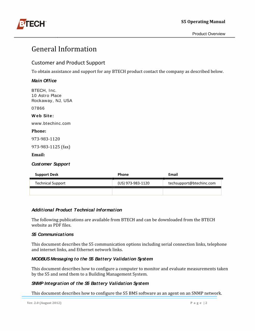
Customer and Product Support
ToobtainassistanceandsupportforanyBTECHproductcontactthecompanyasdescribedbelow.
Main Office
BTECH, Inc. 10 Astro Place Rockaway, NJ, USA
07866
Web Site:
www.btechinc.com
Phone:
973‐983‐1120
973‐983‐1125(fax)
Email:
Customer Support
Support Desk Phone Email
Technical Support (US) 973‐983‐1120 [email protected]
Additional Product Technical Information
ThefollowingpublicationsareavailablefromBTECHandcanbedownloadedfromtheBTECHwebsiteasPDFfiles.
S5 Communications
ThisdocumentdescribestheS5communicationoptionsincludingserialconnectionlinks,telephoneandinternetlinks,andEthernetnetworklinks.
MODBUS Messaging to the S5 Battery Validation System
ThisdocumentdescribeshowtoconfigureacomputertomonitorandevaluatemeasurementstakenbytheS5andsendthemtoaBuildingManagementSystem.
SNMP Integration of the S5 Battery Validation System
ThisdocumentdescribeshowtoconfiguretheS5BMSsoftwareasanagentonanSNMPnetwork.

S5OperatingManual
Product Overview
Ver.2.0(August2012) P a g e |3
Technical Support Bulletins
BTECHpoststechnicalsupportbulletinsasPDFfilesonitswebsite.Thesefilesandothersupportmaterialscanbedownloadedasnecessary.
Customers are encouraged to check the site periodically to see if important new information has been added.
About This Guide
Alloftheinformationcontainedinthisguidewascurrentandaccurateattimeofpublication.ChecktheBTECHwebsitetoseeifany‘Service’or‘Product’updatebulletinshavebeenissuedoradditionaldocumentationpostedfollowingtheGuide’spublication.
Thisguideisintendedtobeprinted‘duplexed’.Ifprinteduniplexsomeblankpageswilloccurwithjustheadingandfootings.ThisisnormalandDOESNOTindicatemissingmaterial.
In some instances Metric measurements in this document have been rounded.
Internal Document Links – MS Word and Adobe PDF
BoththeMSWordandtheAdobePDFdocumentversionscontainembeddedinternallinks.Thelinksconsistofthefollowing:
TableofContents,Figures,andTablesList,
ReferencestoFiguresandpagenumberswithinthetext,
ReferencestoHeadingsandTitleswithinthetext.
Embedded MS Word Links
TofollowalinkinMSWord,placethecursoronalinkitem.Ifthetool‐tipshownbelowappearsholddowntheCtrlkeyandclick.Theuserjumpstothetargetlinklocation
Adobe PDF Files
Placethecursoronalinkitem.Thecursorchangestoapointingfinger(seebelow).Clickandtheuserjumpstothetargetlinklocation.

S5OperatingManual
Product Overview
Ver.2.0(August2012) P a g e |4
Symbols and Terms Used in the Guide
Throughouttheguidethereareitemssetoffbythemselvesandprecededbyoneofthesymbolsshownbelow.Thesymbolindicatesthetypeofinformationanditsrelativeimportance.
Symbol Name Purpose
Note Indicates an important point that customers should be aware of.
Important Indicates a critical, non‐safety related item. In general, failure to comply with these items may result in damage to equipment and voiding of Warranty.
Safety Warning Indicates a procedure that can result in personal injury if not performed properly and with the necessary safeguards in place.
KeyTerms
Keytermsusedthroughoutthismanualaredefinedbelow.RefertoFigure2‐BatterySystemDiagram
Term Definition
Alarm A critical warning requiring immediate attention.
Alarm Relays A physical connection on the rear of the S5 used to pass alarm data to a building system central monitoring station.
Alert Refers to a non‐critical warning. Sometimes called a “maintenance” alert.
Battery The battery backup system in its entirety
Battery Bar or Strap A piece of metal or cable connecting two battery cells/jars
Battery Jar One to six cells enclosed in a common smallest replaceable part
Battery String A set of battery cells/jars wired in series
Battery Unit The smallest segment of the battery being monitored by the S5 system (can be 1 or more cells/jars in a unit)
Controller An individual S5 unit. Sometimes specific to the memory functions.
Observer BVS Observer. A Windows service that runs in the background of the host computer and collects data from the S5.
POTS “Plain Old Telephone Service”. A basic service line used with a dial‐up modem.
Site References a particular S5 unit (i.e. one location can have multiple sites)

S5OperatingManual
Product Overview
Ver.2.0(August2012) P a g e |5
Term Definition
SNMP Simple network management protocol. A IP network protocol that can be used when linking a S5 to battery system locations using a network.
SQL (Sequel) A sophisticated database system that can be used with BVM 4.x
Status Monitor BVS Status Monitor.
IntegratedUserHELP
TheBVMsoftwareincludesintegratedHelpavailablebyclickingHELPinthemenubar.SelectHelpTopicsinthedrop‐downmenu.Atwo‐panescreenisdisplayedwithamastervolumeshownontheleftside,(seeFigure1‐PartiallyExpandedHelppanel
Toviewhelpcontent–
a. Double‐clickonamastervolumeicontoexpandit.Thisdisplaysasetoftopicvolumns,b. Clickonatopicvolumetodisplayitstopics,c. Selectatopictoviewitscontentintherightpane.
Integrated User HELP can be printed by selecting a volume, folder or topic and clicking the Print icon. The complete Help content can be printed by selecting the master volume and clicking the Print icon.
Figure1‐PartiallyExpandedHelppanel

S5OperatingManual
Product Overview
Ver.2.0(August2012) P a g e |6
Figure2‐BatterySystemDiagram

S5OperatingManual
Installing the Software
Ver.2.0(August2012) P a g e |7
2. Installing the Software
BVMSoftwareApplications
BatteryValidationMonitor(BVM):Enablesuserstoanalyzeandinterpretallmeasurementdatabyprovidingagraphicalanalysisofperformance.Italsoservesasthedirectlinktothecontrollertomanipulatesystemsettings,clearalarms,orenterthesystem’sdiagnosticmode.Additionally,itprovidesareal‐timedischargedataloggerthatenablesuserstoviewongoingvoltageandcurrentinformationduringadischargeeventordischargetest.
BVSObserver:ObserverisaWindowsservicethatrunsinthebackgroundonthehostPCandperiodicallycollectsthelatestmeasurementdatafromthebatterymonitoringsystemcontrollers,(S5s).Overtime,avaluablebatterytrenddatabaseisbuiltthatcontinuallytracksthebatterysystem’sperformanceandcomparesitwithresultsobtainedwhenthebatterysystemwasnew.
BVSStatusMonitor:Providestheuserwithasummaryofall,oragroupofbatterysystems'status.Itprovides‘drill‐down’functionalityfromallofthebatterysystemstoindividualunitsbylaunchingtheBVM.ItalsoprovidestheuserwithanaudibleandvisiblealertwhennewalarmsarereceivedbytheBVSObserver.
BVM Filed Types
DatabaseFiles:BVMinstallsoneormoredatabasefilesinthe“BVMData”folder.Generallytheseare“MSAccess”filesbuttheuserhastheoptionofswitchingtoSQLdatabasesiftheyprefer.
.bvmFile:Microsoftdatabasefile.
.setFile:ThesearesuppliedbyBTECandcontaintheinitialcontrollersettingsbasedonmanufacturerspecifications.Userscanoveridethefilecontentorcreatenew.setfilesasneeded.Itisparticularlyreleventtobackingupandrestoringthecontrollersettings,(seeTheGet/SetConfiguration,onpg.63).WhenmultiplelocationsaremonitoredbyanS5therewillbeone.setfileforeachlocation.
.mibfiles:ThesearesuppliedbyBTECHonanas‐neededbasis.TheyareusedwhenacustomerimplementsSNMPtrapsinanetworkenvironment,(seeSNMPManagerDescriptionandConfiguration,beginningonpage136).
The.bvmand.mdbfilesMUSThavematchingserialnumbersandMUSTbelocatedinthesamedirectory.
The BTECH installation disk includes a copy of Microsoft’s SQL Server Express. A number of other Microsoft SQL server packages will also work with BVM 4.x (see Appendix). For sites using ‘Server Express’, BTECH provides a stored procedure for use with back‐ups.

S5OperatingManual
Installing the Software
Ver.2.0(August2012) P a g e |8
All BTECH application and data files should be included as part of regular computer or server backup scheduling.
ThereisoneeachofthefollowingprogramfilesforeachS5unitintheinstallation.TheyarecreatedbyBTECHspecificallyforthesiteandareidentifiedbytheserialnumberoftheunit.Theymustallbeinthesamedirectoryonthehostcomputerortheserver’sharddrive.
Sitename+SerialNumber.mdb–ThisisaMicrosoftAccessdatabasefile,
Sitename+SerialNumber.bvm–TherewillbeoneofthesefilesforeachS5,
Sitename+SerialNumber.set–Thisisatextfilecontainingthesitesettings.
Installation Machine Requirements
ThefollowingWindowsandcomputerhardwarespecificationsarerequired.
MachineRequirements
OS Processor Memory HD Space Display
Windows XP (SP3) (32‐bit) or
Windows 2003 (32‐bit)
800 MHz Pentium III
512 MB 100 MB for programs and small data files
1024 x 768
Windows Vista (32‐bit)
Windows 2008 (32‐bit)
Windows 7 (32‐bit)
1.4 GHz – x86 or x64 processor
2 GB 100 MB for programs and small data files
1024 x 768
Windows Vista (64‐bit)
Windows 2008 (64‐bit)
Windows 7 (64‐bit)
2 GHz – x64 processor
2 GB 100 MB for programs and small data files
1024 x 768
Mouse or other pointing device
Dial‐up modem if one or more S5 units will utilize communication over a POTS line.
IP network connection for sites communicating over a network.
The BVM software can be run on a virtual machine provided that the processor resources, memory, and disk space described above are available.
InstallationFilesandDirectoryStructure
WhentheBVMsoftwareisinstalledonalocaldiskitcreatesanew,BVM4directoryandvariouscertainsub‐folderswhereitcopiesfiles.Someadditionalfilesarespecifictoeachparticularlocationandmustbetransferredtothehostcomputerorservermanually,(seeStartingObserverandAddingLocations,,pg.10).Otherprogramsareplacedinspecificfolderswheretheymustremainorthesystemwillnotfunctionproperly.SeeFigure3,page9,foranillustrationofthefolderstructure.

S5OperatingManual
Installing the Software
Ver.2.0(August2012) P a g e |9
InstallingtheBVMSoftwareonaWindows‐basedPCorServer
TheBVMsoftwareissuppliedonastandardCD‐ROM.OncetheinstallationiscompletetheCDandsleeveshouldbekeptinasafelocationforfutureuse.TheCDcanbeusedtoactivatefutureversionsoftheBVMsoftware.
Figure3‐TheBVM4.xInstallDirectory
Toinstallthesoftwareusethefollowingprocedure,(seeFigure4,below).
a. InserttheBVMsoftwareCD‐ROMintothemachine’sCD.InafewmomentstheAutoplaypanelisdisplayed.
b. ClickrunBVM_4.x.x_Setup.exe.c. IntheresultingoptionscheckboxselectthefollowingitemsbasedontheInstallation: InstallBVSObserveriftheS5willbemonitoredonafull‐timebasis,byaserverordedicated
workstation,(onlyoneinstanceofBVMcanberunonanetwork).
InstalltheUSBComPortdriveriftheS5willbemonitoredbydirectlyconnectingacomputerviaaUSBcable.
TheUpdateSystempanelisdisplayedshowingaprogressbarindicatingtheinstallationstatus.IftheBVMSoftwareActivationdialogisdisplayedrefertoActivatingBVSObserver,pg.12.Thisonlyoccursundercertaincircumstances.
d. SelectthedesireddestinationfolderandclickNext. MSWindowsselectsadefaultdriveandfolderforthesoftwareinstallationonthecomputer’s
harddrive.Ingeneralit’sbesttoacceptthedefault.ToinstalltheBVMsoftwareinanotherlocation,clicktheBrowsebuttonintheDestinationFolderboxtodisplayalistofdrivesandfolders.
e. ClickFinishwhenthe“successfulinstallationdialog”isdisplayed.

S5OperatingManual
Installing the Software
Ver.2.0(August2012) P a g e |10
Figure4‐BVM4InstallationComponentSelectionDialog
Do not remove the CD‐ROM from the computer at this time. Some BVM files must be transferred from the CD to the BVM directory on the computer’s hard drive.
Adding Locations to BVM
IntheS5‘world’a“location”referstoaspecificbatterysystembeingmonitoredbyanS5controller.Forillustrationpurposesthisguideusesonlyonelocationwithtwostrings.TheBVMsoftwaredeliveredwiththeS5unit(s)includesa.bvmfileforeachS5unitintheorder.ThesefilesmustbetransferredtotheBVMapplicationfoldermanuallybeforebatterymonitoringcantakeplace.
The .bvm files MUST be transferred as described in this section. They CANNOT be copied and pasted.
All files for a specific site will be labeled:
[location id]+S5+[sequence #]+x4.bvm
where the sequence number = 1,2,3, etc, (see Figure 5, page 11).
Starting BVM and Transferring Location Files from the CD
TheBTECH‐suppliedCDincludesoneormorecustomfilesusedbytheBVMsoftware(one.bvmfileforeachS5beingadded).ThesefilesareNOTcopiedduringtheinstallationprocessandmustbetransferredtotheBVM4folderonthecomputer’sharddriveusingtheBVMapplication.Asshownabove,each.bvmfileisuniquelyidentifiedbyitsserialnumber.
a. StarttheBVMsoftwarebydoingeitherofthefollowing:
IfthereisaBVMiconintheWindowsStartmenu clickonit,

S5OperatingManual
Installing the Software
Ver.2.0(August2012) P a g e |11
OpentheWindowsStartmenuandselect“Allprograms”.NavigatetotheBTECHfolderanddouble‐clickontheBatteryValidationManager4.xentry.
b. ThefirsttimetheBVMsoftwareisstarted,adialogwillappearaskingiftheuserwantstoaddLocations.ClickYes.TheLocationListscreenisdisplayed(seeFigure5below).
The Location List Screen
c. IntheLocationListscreenclicktheAddLocationsfromCDbutton,aWindowsExplorerdialogopens. NavigatetotheInstallationCDifnecessary.
d. InExplorer,selectthecorrect.bvmfileusingitsserialnumberandclickOpen.
TheuserreturnstotheLocationListscreenwhichispopulatedwiththeselectedfile.Repeatthisprocessforeachavailablefile.Onceallsitefileshavebeenadded,theCDcanberemovedfromthecomputer,placedinitssleeve,andstoredinasafelocation.
If the number of installed S5 units increases, a corresponding .bvm file (provided by BTECH) must be added as described above.
If the number of installed S5 units decreases, the corresponding .bvm file(s) for the unit(s) should be deleted from the Location List screen.
Figure5‐TheLocationListscreenwithWindowsExplorerinset
InstallingtheBVSObserverSoftware
TheBVSObserversoftwareshouldbeinstalledanytimetheS5willbemonitored24/7byadedicatedcomputerorserverconnectedeitherdirectly,oroveraTCP/IPnetwork(seeInstallingBVM4.xSoftwareonaServer,pg.112).

S5OperatingManual
Installing the Software
Ver.2.0(August2012) P a g e |12
Adding S5 Locations to Observer
ThesamelocationsaddedtoBVMmustalsobeaddedtoObserver.ThisprocessisessentiallyidenticaltotheprocessusedforBVM.ObserverhasthesamehardwareandOSrequirementsasBVM.
Starting Observer and Adding Locations
ObserverservesasdatacollectorandautomaticallyretrievesthelatestmeasurementsandalarmsfromtheS5controlleronauser‐definedschedule.Italsobuildsabatteryperformancedatabaseontheserverorhostcomputer.Ifconfiguredforitcanalsodistributedetailedemailand/orcellphonealarminformationtextmessages.
ObserverisinstalledalongwiththeBVMsoftwareintheBVM4folderonthehostcomputer.LikeBVM,itmustbecorrectlyconfiguredforeachlocation.ThefirsttimeObserverisstarted,locationsmustbeaddedtoit.TostartObserverusethefollowingprocedure.
a. NavigatetotheBVMfolderonthecomputer’sharddrive,b. Double‐clicktheObservericontostarttheprogram.TheLocations.cfg–Observerscreenis
displayed,(seebelow),
c. Clickontheplussign(+),orclickFileandselectAddLocation(s)inthemenulist.AWindowsExplorerscreenopens,
d. Navigatetothelocationfilestobeaddedandselectthem,
To select multiple locations in the Windows Explorer screen hold down the Control key (Ctrl) and click on the individual locations.
e. ClickOpen.TheselectedfilesareaddedintheLocations.cfg–Observerscreen.
Figure6‐TheLocations.cfg–ObserverScreenwithaLocationSelected
Activating BVS Observer
THEFOLLOWINGSTEPISONLYREQUIREDIFTHEACTIVATEBVSOBSERVERSOFTWAREDIALOGISDISPLAYED

S5OperatingManual
Installing the Software
Ver.2.0(August2012) P a g e |13
IftheBVSObserversoftwarevalidationdialogisdisplayedaspartoftheinitialinstallprocess,entertheinstallationcodeprintedontheCDsleeve(seebelow).Thiscanoccurewhen10ormoreS5sareusedinthesystem.
a. Typethe16‐charactercodeprintedontheCDsleeveintothefourboxesshownintheActivationdialog.Typefourcharactersineachbox,seebelow.
b. ClickOK.c. ClickFinishwhenthesuccessfulinstallationwindowisdisplayed.
The Activation dialog is displayed only when a location has at least ten (10) S5 units installed.
Figure7‐TheActivateBVSObserversoftwaredialog
TheBVMHomeScreen
TheBVMHomescreen(seeFigure8,pg.16)providesasummaryoftheselectedlocationaswellasquickaccesstovariousadditionalfeaturessuchasreports,andgraphs.
Status Colors
TheBVM4HomescreenisdisplayedwhenaparticularsiteisopenedfromtheLocationListscreenandprovidesaccesstoalargenumberoffeatures.Stringsandindividualbatteriesareshowninoneofthreecolors,basedonthelatestsetofmeasurements.
Green–Systemisrunningwithinsetpointsandisconsideredtobehealthy.Noanalysisofthesystemisnecessary.
Yellow–Systemisinmaintenancestatusbasedonpredeterminedsetpoints.Analysisofthestringisrecommededunlessthealertcauseisalredyknown.
Red–Systemisincriticalalarmstatusbasedonpredeterminedsetpoints.Detailedanalysisoftheindicatedstring(s)shouldbeperformedimmediately.

S5OperatingManual
Installing the Software
Ver.2.0(August2012) P a g e |14
Quick Measurements
Thesemeasurements(sometimesreferredtoas“ToolTips”)appearwhenthecursorisplacedonaniconintheHomescreen.
More detailed data can be viewed using the options listed under Reports and Graphs in the menu bar. Consult the following Guide sections:
7 Reports, beginning on page 80, 8 Graphs, beginning on page 97
Home Screen Display Options
Whilethestatuscolorcodingispermanent,theuserhaslimitedcontroloverthewaybatterysystemarchitectureisdisplayed.FordetailsonchangingtheHomeScreendisplaysee:BVMHomeScreenDisplayOptions,beginningonpage128.
The Home Screen Menu and Icon Bar
TheHomeScreenmenubarprovidesaccesstoavarietyoffunctionscoveredinthisguide(seeFigure9,pg.17).TheavailabilityofitemsontheIconbarvariesdependingonMenu/Submenuselections.Availableitemsaredisplayedatfullvalue.Unavailableitemsaredisplayedinshadesofgray.Seenextillustration.
Basic Individual Battery Measurements
Toviewbasicmeasurementsforasinglebatteryplacethecursoroverthebattery’snumberedblocktodisplayatooltipwiththefollowingdata.
Unit#,String#–Thisidentifiesthespecificbatterybyitsstringandsequencewithinthestring.
UnitVoltage–VoltsDC.
UnitImpedance–inmilOhms.
UnitTemperature–PilotcelltemperatureinFahrenheitorCelsius(userselectable).
Individual Battery Measurement Graphs
Double‐clickingonthebatteryicondisplaysadatedialog(seeFigure80,page97).Byenteringaspecificdate,(ordaterange)ausercangraphthedata.WithinthegraphtheusercanselectVoltage,Impedance,orTemperaturebyselectingtheappropriateiconinthetoolbar.
The graphs available from the battery rectangle are also available from the Home Screen Graph menu. For additional information and examples refer to:
Graphs, beginning on page 97.

S5OperatingManual
Installing the Software
Ver.2.0(August2012) P a g e |15

S5OperatingManual
Installing the Software
Ver.2.0(August2012) P a g e |16
Figure8‐‐AnexplodedillustrationoftheBVMHomescreen
S5OperatingManual
Installing the Software
Ver.2.0(August2012) P a g e |17
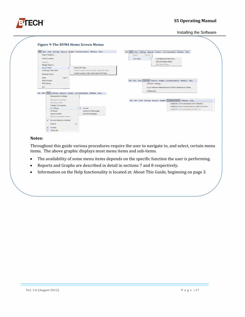
Figure9‐TheBVM4HomeScreenMenus
Notes:
Throughoutthisguidevariousproceduresrequiretheusertonavigateto,andselect,certainmenuitems.Theabovegraphicdisplaysmostmenuitemsandsub‐items.
Theavailabilityofsomemenuitemsdependsonthespecificfunctiontheuserisperforming.
ReportsandGraphsaredescribedindetailinsections7and8respectively.
InformationontheHelpfunctionalityislocatedat:AboutThisGuide,beginningonpage3.

S5OperatingManual
S5 Start-Up
Ver.2.0(August2012) P a g e |18
3. S5 Start‐Up OncetheS5controllerhasbeeninstalledandthesoftwareloadedontothecomputer,thecontrollerandcomputermustbelinkedandthelocationsconfigured.FornewinstallationsinitialS5controllerlocationfilesmustbeaddedtotheBVMsoftware.
ConnectingaComputertotheS5ControllerViaUSBCable
InordertoloadtheBVMsoftwareandcompleteaninitialS5configurationahostcomputermustbeconnecteddirectlytotheS5unit.ToconnectalocalcomputertoanS5,usetheBTECH‐providedUSBcommunicationcable.
a. PlugtheUSBcableintotheportontheS5frontpanel,andtoanavailableUSBportonthecomputer,
b. IntheBVMmenubarclickCommunicationsandselectEstablishLocalCommunicationswithControllerfromthesubmenu.TheLocalCommunicationSettingsdialogisdisplayed(seebelow),
c. IftheCommPortlistboxisnotshowingadefaultentry(orifthedefaultisincorrect)clickthedrop‐downarrowandselectthecommunicationsporttobeusedtoconnecttotheS5, Enterthecorrectportnumberifitdoesnotappearinthedrop‐downlist.
d. IftheCommSpeeddrop‐downisavailableselectthecommunicationspeedoracceptthedefault,
e. ClickOKtoopenthecommunicationsportandestablishcommunicationswiththecontroller, NOTE:ThesecommunicationparametersbecomethedefaultsusedbytheBVMsoftwareas
longasthesameUSBportisutilized.
f. ClickOKinthedialogaskingif‘allnewdatashouldberetrieved’.
TheCommunicationsscreenisnowdisplayed.Itservesasthebaseor‘core’locationfortheremainderoftheconfigurationprocess,(seeFigure12,pg.22).
Figure10‐LocalCommunicationsSettingsdialog

S5OperatingManual
S5 Start-Up
Ver.2.0(August2012) P a g e |19
Start‐upforNewLocations
ThefirsttimethatBVMisstarted–andanytimeanewlocationisaddedandconfigured–thisprocedureshouldbefollowed.
a. ConnecttheS5unitandthecomputerusingtheUSBcable(see“ConnectingaComputertotheS5ControllerViaUSBCable“beginningonpage18),
b. TurntheS5ONandstarttheBVM4softwarebyclickingtheBVMicon inthestartmenu.Alocationlistscreenisdisplayed,(seeFigure11,below), IftheBVMLocationListscreenisnotdisplayedwhenthesoftwareisstarted–clickFileinthe
menubarandselectOpenintheoptionlist.
c. SelectthelocationtoconfigureintheLocationListscreenandclickOK. Ifthetargetlocationisnotlisteditmustbeadded.See“AddingLocationstoBVM”,beginning
onpage10.
TheBVMhomescreenisdisplayedfortheselectedlocation,(seeFigure8,pg.16).
The serial number of the S5 and the selected site MUST match or errors will be generated by the controller.
The first time a location is opened the user is given an option to add and configure user privileges. This can be done at this point or any time in the future. see: Managing Users, beginning on page 34.
For sites with multiple S5s, each unit must be set up individually.
Opening the Communications Screen
Mostoftheinitialstepsforconfiguringalocationareaccessedfromthemaincommunicationsscreen.Usethefollowingprocedure.
a. IntheHomescreenmenubarclickCommunicationsandselectEstablishLocalCommunicationswithController,(seeFigure9,pg.17),
b. IntheCommunicationsdialog: AcceptorchangetheCommPortandCommSpeedsettingsandclickOK.
c. Thefirsttimealocationisopenedan[BVM]errordialogisdisplayed.Thisisnormal.ClickOK.
d. ThemainCommunicationsscreenisdisplayed,(seeFigure12‐ ,pg.22).

S5OperatingManual
S5 Start-Up
Ver.2.0(August2012) P a g e |20
Figure11‐TheBVM4LocationsListScreen‐
Reviewing the Battery System Configuration
ThelocationfileprovidedbyBTECHwiththeS5containsdataonthebatterysystem.Thisprocedurecheckstheactualsystemconfigurationagainstthefiledata.
a. ClickAdvancedinthemainCommunicationsscreenandclickSystemConfiguration.A
groupofsixpropertysheetsaredisplayed,(seeFigure12‐ ,pg.22),b. IntheSystemConfigurationpropertysheetclicktheModuleConfigbuttontodisplaythe
ModuleConfigurationscreen,(seeFigure12‐ ,pg.22),c. ClicktheModuleDiagnosticsbuttontodisplaytheModuleDiagnosticsscreen,(seeFigure
12‐ ,pg.22),
Thefirsttimethisscreenisopeneditperformsanauditonthedefaultmodule(Module1)anddisplayresultsatthebottomoftheUnitsAssignedandTempscolumns.Thecountforeachgroupshouldbeidentical.
UnitsAssignedmustequalUnitsFound
TempsmustequalTemps[Found]
d. ClicktheModuledrop‐downandselectthenextmodule.Repeatthisprocedureforallmodulesinthesystem.
If the totals for any module do NOT match, a problem with the battery system hardware connections is present. Resolve the hardware issue, see Equipment Checks and Troubleshooting, beginning on page 67.
When the problems have been corrected repeat this procedure.
Re‐learning the Connections
OncetheModuleDiagnosticresultsarecorrectthenextprocessistore‐learntheconnections.Proceedasfollows.

S5OperatingManual
S5 Start-Up
Ver.2.0(August2012) P a g e |21
a. NavigatetothemainCommunicationsscreenandclickAdvancedifnecessary(seeFigure12‐,pg.22),
b. ClickonSystemConfigurationtodisplaythepropertysheets,c. IntheSystemConfigurationpropertysheetclicktheClearMemorydrop‐downarrow,(see
Figure12‐ ,pg.22),d. ClickRelearnConnectionsinthedrop‐downlistandclickOKintheWarningdialog.
TheCommunicationscreenelementsareallunavailable(grayedout)forabrieftimeperiod.Whenthescreenisrefreshedtheprocessiscomplete.IftheCommunicationsscreenindicatesanerrorthecausemustbecorrectedandthisprocedurerepeated.
Obtaining Preliminary Measurements
Initialmeasurementsareobtainedusingthefollowingprocedure.
a. NavigatetothemainCommunicationsscreenandclickAdvancedifnecessary(seeFigure12‐,pg.22),
b. ClickPerformMeasurementstocapturebatterydatatothecontroller,(seeFigure12‐ ,pg.22), Thescreencontrolswillbecomeinactiveforaperiodoftimeuntil“MeasurementComplete”
appearsinthestatusline.
c. ClicktheRetrieveDatadrop‐downarrowandselectRetrieveAllinthelist.Thedatahasnowbeenupdatedtothecomputer,(seeFigure12‐ ,pg.22). ClickOKifadialogisdisplayed.
Foralarge,multi‐stringsite,measurementscantakeuptoapproximately2hours–duringwhichthecontrollerisunavailable.

S5OperatingManual
S5 Start-Up
Ver.2.0(August2012) P a g e |22
Figure12:ConfigurationProcedureScreenFlow
Verify the Measurement Data
Impedance(togetherwithvoltageandtemperature)start‐updataisverifiedthroughthe“Graphs”function.
a. IntheHomescreenmenubarclickonGraphsandselectSnapshotofUnitMeasurements,(seeFigure9,pg.17), seeUnitSnapshotGraph,beginningonpage100foradescriptionofthegraphdata.
b. Selectthecurrentdateinthedatedialog,

S5OperatingManual
S5 Start-Up
Ver.2.0(August2012) P a g e |23
Whenthegraphisdisplayedthedefaultmeasurementis‘Voltage”.ClicktheImpedancesymbolin
theiconbar, ,(seeFigure8,pg.16).
Itisadvisabletoalsocheckvoltageandtemperaturedatabyclickingtheirrespectiveicons.
PressingF10willcyclethroughtheavailablegraphs.
If the data indicates a problem, resolve the issue(s) before continuing.
ImpedanceMultipliers
Obtaining Baseline Impedance Values
CertainparametersmustbesetoncethecomputerandtheS5controllerarecommunicating.ThisisdonefromvariousfunctionscontainedintheprimaryCommunicationsscreen.UtilizingthisscreentheusercanacquireabasesetofmeasurementsfromtheS5,savethemtotheS5’slocationfile,andstoretheminthecontrollermemory.
ImpedanceMultiplierscompensatefortheoutputimpedanceofthebatterycharger,theimpedancesofotherparallelstringsofcells,andalsoDCbuswiringandswitching.Theycanbesetforsystemsrequiringtheimpedancemeasurementstohaveabsoluteaccuracy(ascontrastedwithrelativeaccuracy).Multipliersexistforboththepositiveandnegativehalfofeachstring.Multipliersaresetusingtheautomatedfunction.
Setting Impedance Multipliers automatically can be done when – and only when –
There are an equal number of batteries in the positive and negative halves of the string,
In ALL other situations impedance multipliers must be set manually. Before attempting to set multipliers manually, customers should contact the BTECH Technical Support department for assistance.
Setting Impedance Multipliers Automatically
a. NavigatetothemainCommunicationsscreenandclickAdvancedifnecessary(seeFigure12‐,pg.22),

S5OperatingManual
S5 Start-Up
Ver.2.0(August2012) P a g e |24
Figure13‐ImpedanceMultipliersPopulatedAutomatically
b. ClickSystemConfiguration.TheSystemConfigurationpropertiestabscreenisdisplayed,(seeFigure12‐ ,pg.22),
c. ClicktheImpedanceMultiplierspropertytab.Thepropertiesaredisplayed,(seeabove),d. ClickAutoMultiplierSetUp.BVMbeginscapturingimpedancedatafromeachunit, Thenewdatapopulatesthescreenfields.
e. IntheChooseUnitsdialogselectthePositiveandNegativehalfunits,(seebelow). BTECHrecommendsNOTusingthefirstorlastunitinthisprocedure.
Figure14‐TheChooseUnitsdialog
It takes about 15 seconds per unit to acquire each reading. Depending on the overall size of the installation it may take several minutes to complete the process.

S5OperatingManual
S5 Start-Up
Ver.2.0(August2012) P a g e |25
Setting Impedance Multipliers Manually
Setting Impedance Multipliers Manually
Thisoptionisgenerallyusedonlywhenthenumberofunitsinthepositiveandnegativepartsofthestringareunequal.BTECHstronglyadvisesthatcustomersconsultwiththeTechnicalSupportdepartmentpriortomakinganymanualimpedancechanges.
Obtain a New Set of Base Measurements
OncetheImpedanceMultipliershavebeenset,new,post‐Impedancemultipliervaluesmustbeobtained.
Repeat“ObtainingPreliminaryMeasurements”,page21.
Generally it is not necessary to repeat the data verification procedure.
Copy Initial Impedance Values to BVM Software Settings
Thenewdataobtainedinthisprocedureisusedfortrendanalysisaswellasanyuser‐requestedreportsorgraphs.
a. NavigatetothemainCommunicationsscreenandclickAdvancedifnecessary(seeFigure12‐,pg.22),
b. ClicktheInitialImpedancedrop‐downarrow,c. Select“RetrieveInitialImpedanceMeasurementsfromControllerandSavetoBVMSoftware
UnitSettings”,(Figure12‐ ,pg.22)d. SelectthedateofthemeasurementsandclickYesintheconfirmationdialog,e. ClickOK.
Theunit’sinitialimpedancemeasurementsintheBVMsoftwaresettingshavenowbeenreplacedwiththedatafromtheselecteddate.
Load Initial Impedance Values to the S5 Controller
Thenewdataobtainedinthisprocedureisusedfortrendanalysisaswellasanyuser‐requestedreportsorgraphs.
a. NavigatetothemainCommunicationsscreenandclickAdvancedtodisplaytheoptionscontainedinthescreenextension,(seeFigure12‐ ,pg.22)
b. ClicktheInitialImpedancedrop‐downarrow,c. Select“LoadInitialImpedanceMeasurementstotheControllerfromtheBVMSoftware,”d. ClickYesintheconfirmationdialog,e. ClickOK.

S5OperatingManual
S5 Start-Up
Ver.2.0(August2012) P a g e |26
Theunit’sinitialimpedancemeasurementsinthecontrollerhavenowbeenreplacedwiththedatafromtheselecteddate.
ChangingSoftwareSetting
Units Properties
OncethenewimpedancevalueshavebeenaddedtothecontrollerandtoBVM,somesoftwareconfigurationchangesmustbemade.
a. IntheHomescreenmenubarclickSettings,andselectSoftwareSettings.Agroupoftabbedpropertysheetsaredisplayed,(seeFigure8,pg.16),
b. ClicktheUnitsPropertiessheet,c. In“Impedance”(midsectionofthescreen)clicktheAnalysisMethoddrop‐downarrowand
selectInitialfromthelist,(seebelow),d. ClickOKtochangethesetting.
Changing Controller Settings Properties
a. NavigatetothemainCommunicationsscreenandclickAdvancedtodisplaytheoptionscontainedinthescreenextension,(seeFigure12‐ ,pg.22),
b. ClickControllerSettings.Agroupoftabbedpropertysheetsisdisplayed,
c. SelecttheUnitLimitssheet,(seeFigure15‐ below),d. ClicktheAnalysisMethoddrop‐downandselect“Initial”,e. ClickOKtochangethesetting.
Adding Setup Notes
BTECHstronglyadvisesthatsetupnotesbeaddedtoBVMoncethesetupproceduresarecomplete.Thisisaccomplishedusingthefollowingprocedure.
a. NavigatetotheBVMhomepage(seeFigure12,pg.16),b. ClicktheMeasurementListingsbuttonatthebottomoftheleftpanel.TheMeasurementsheet
isdisplayed,(seeFigure60,pg.83),

S5OperatingManual
S5 Start-Up
Ver.2.0(August2012) P a g e |27
Figure15‐UnitSettingsPropertySheet
c. Selecttherecordforthecurrentdate(usuallyatthelistbottom).d. Rightclickandselect“EditMeasurementNote”,fromthecontextmenu, ClickOKintheSelectMeasurementdialog.
e. IntheNotedialogenterabriefcommentaryincludingthesitelocationandtechnicialID.ClickOKwhenfinished. Enter“Thisdatausedforinitialimpedance”.
NotescanbeeditedatanytimehowevertheuserislimitedtothecolumnspaceintheMeasurementsheet.
Identifying Problems
IftheS5systemindicatesanalarmoralertusethefollowingproceduretoidentifythecause.
NavigatetotheBVMHomescreenandclickMeasurementListingsatthebottomoftheleftpanel,(seeFigure8,pg.16).
a. IntheMeasurementListing’sthree‐tabsheetscreenselectAlarmsandAlerts,page3,(seeError!Referencesourcenotfound.,pg.29).
b. IdentifyanyAlarm/Alertmessagesforthedateandtimethatthestartupprocesswasbegun.

S5OperatingManual
S5 Start-Up
Ver.2.0(August2012) P a g e |28
TheAlarmandAlertscolumnmessage(s)indicatethesourceproblem(s)thatmustbecorrected.Onceallproblemshavebeenresolved,clearthealarmstateasdescribedbelowandcontinuewiththestartup.
Acknowledging Alarms and Alerts
Oncethehardware/softwareproblem(s)iscorrectedusethefollowingproceduretoacknowledgetherecordintheAlarms/Alertscolumn(seeError!Referencesourcenotfound.,below).TheAlarm/Alertmessage(andtheacknowledgement)willremainaspartofthelog.
a. NavigatetotheCommunicationsscreenandclicktheRetrieveDatadrop‐down,b. SelectRetrieveAlarmsandAlertsfromthedrop‐downlist.Thiscopiesthealarmdatatothe
BVMsoftware,c. NavigatetotheBVMHomescreenandclickMeasurementListingsatthebottomoftheleft
panel,d. IntheMeasurementListing’sthree‐pagescreenselectAlarmsandAlerts–page3,e. Selectthealarmoralerttobeacknowledged, NOTE:MultipleAlarms/AlertscanbeselectedbyholdingdowntheCtrlkeywhileselecting
individualentries.
f. Right‐clicktodisplayapopupmenuandselectAcknowledgeAlarm(s).ClickOKintheconfirmationdialog, BVMpopulatesthe“Acknowledged”and“ByUser”columnsfortheselectedentry(ies)with
userdata,andclearsthealarm.
g. ClosetheAlertsandAlarmspagebyclickingthered“X”inthecornerandnavigatebacktotheCommunicationsscreen.
Setting Read Date/Time
Atstart‐uptheS5needstohavethecurrentdateandtimesetsothatitcanaccuratelylabeleventsandperformcertainscheduledtaskscorrectly.Usethefollowingprocedure.
a. NavigatetotheCommunicationsscreen(seeFigure31,pg.48), NOTE:expandthescreenbyclickingtheAdvancedbuttonifnecessary.
b. ClickCheckTime.Thescreen’sStatuslinedisplaysthetimetheS5currentlyhasinitsmemory. IftheS5timeandthehostcomputertimediffer,adialogsuggestingthatthedate/timesbe
synchronizedisdisplayed.ClickOK.

S5OperatingManual
S5 Start-Up
Ver.2.0(August2012) P a g e |29
Figure16‐TheAlertsandAlarmspagewithpopupmenuinserted.
Scheduling Periodic Measurement Readings
MeasurementscanbedownloadedtotheS5’scontrolleronauser‐enteredschedule.Thisusuallyprovidesthemostconsistentdatasetfortrendingandotherpurposes.Manualreadingscanstillbetakenifnecessary.
a. NavigatetotheControllerMeasurementSetuptab,b. Enterthedate‐timeinformationusingthespinboxlocatedintheintheMeasurementInterval
block, TheDateandTimeentriesintheNextMeasurementblock(re‐)adjustautomatically.
c. IntheMeasurementFreq[uency]drop‐downlist,selecttheappropriatefrequency.
Themeasurementswilloccurautomaticallyonthescheduleentered.Schedulescanberevisedasnecessary.
Alarm Output Relays
ThealarmoutputrelaysconnecttheS5toabuildingmanagementsystem.Asshownbelowuptosixoutputrelayscanbeconnected.
Figure17‐SchedulingControllerMeasurementsAutomatically
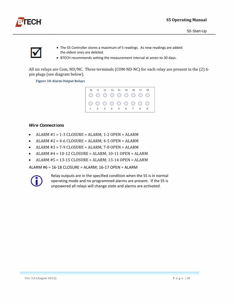
S5OperatingManual
S5 Start-Up
Ver.2.0(August2012) P a g e |30
The S5 Controller stores a maximum of 5 readings. As new readings are added the oldest ones are deleted.
BTECH recommends setting the measurement interval at seven to 30 days.
AllsixrelaysareCom,ND/NC.Threeterminals(COM‐ND‐NC)foreachrelayarepresentinthe(2)6‐pinplugs(seediagrambelow).
Figure18‐AlarmOutputRelays
Wire Connections
ALARM#1=1‐3CLOSURE=ALARM;1‐2OPEN=ALARM
ALARM#2=4‐6CLOSURE=ALARM;4‐5OPEN=ALARM
ALARM#3=7‐9CLOSURE=ALARM;7‐8OPEN=ALARM
ALARM#4=10‐12CLOSURE=ALARM;10‐11OPEN=ALARM
ALARM#5=13‐15CLOSURE=ALARM;13‐14OPEN=ALARM
ALARM #6 = 16‐18 CLOSURE = ALARM; 16‐17 OPEN = ALARM
Relay outputs are in the specified condition when the S5 is in normal operating mode and no programmed alarms are present. If the S5 is unpowered all relays will change state and alarms are activated.

S5OperatingManual
Configuring the BVM and BVS Software
Ver.2.0(August2012) P a g e |31
4. Configuring the BVM and BVS Software
ThesitefilesaddedtotheBVMsystemhavebeenconfiguredatthefactoryaccordingtothebatterymanufacturer’sspecifications.Afewitems(e.g.timezones,temperaturescale)mustbesetlocally.Anyofthesoftware’ssettingscanbemodifiedasnecessaryalthoughthisshouldonlybedonewhenabsolutelynecessary.
SettingsarecheckedandchangedfromtheBVMmenubardisplayedintheHomescreen(seeFigure9,page17).Somesettingsarespecifictoeachsiteandconsequentlythisproceduremustbeperformedeachtimeasite(anewS5unit)isadded.Certainsite‐specificmeasurements(e.g.Impedance)mustberecordedfromthebatteryinstallationandloadedintothehostcomputer.
Figure19‐SettingsMenuMap
DownloadingandCopyingLocalMeasurements
Unlocking a Location File
WhentheBVM opensalocationfile,itlocksthefiletopreventanotherBVMfrommakinganychangestothesettings(notthedata).Ifalocationfileremainslocked,thiscommandisavailabletounlockthelocationfilemanually.Beforedoingso,makesurethelocationfileisnotbeingusedbyanyoneelse.
a. Selectthelocationtobeunlocked,b. ClickFile‐Unlocktounlockthelocation. Ifthe‘Unlock’submenuoptionisgrayedout,thelocationfileisnotlocked.
Data Merge Functions
Thismenucommandmergesdatafromaselectedlocationfileintothecurrentlyopenlocation.Afterselectingthiscommand,aWindowsExplorerFileOpendialogboxappearswheretheusercanselectthesourcelocationfile.Oncethefileisselected,thelocationisopenedandvariouscriteriaarecheckedtoensurethatthedatabeingmergedisfromthe
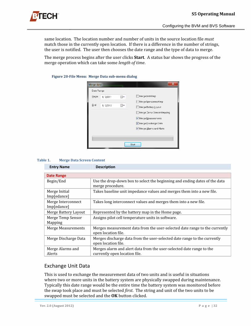
S5OperatingManual
Configuring the BVM and BVS Software
Ver.2.0(August2012) P a g e |32
samelocation.Thelocationnumberandnumberofunitsinthesourcelocationfilemustmatchthoseinthecurrentlyopenlocation.Ifthereisadifferenceinthenumberofstrings,theuserisnotified.Theuserthenchoosesthedaterangeandthetypeofdatatomerge.
ThemergeprocessbeginsaftertheuserclicksStart.Astatusbarshowstheprogressofthemergeoperationwhichcantakesomelengthoftime.
Figure20‐FileMenu:MergeDatasub‐menudialog
Table1. MergeDataScreenContent
Entry Name Description
Date Range
Begin/End Usethedrop‐downboxtoselectthebeginningandendingdatesofthedatamergeprocedure.
MergeInitialImp[edance]
Takesbaselineunitimpedancevaluesandmergesthemintoanewfile.
MergeInterconnectImp[edance]
Takeslonginterconnectvaluesandmergesthemintoanewfile.
MergeBatteryLayout RepresentedbythebatterymapintheHomepage.MergeTempSensorMapping
Assignspilotcelltemperatureunitsinsoftware.
MergeMeasurements Mergesmeasurementdatafromtheuser‐selecteddaterangetothecurrentlyopenlocationfile.
MergeDischargeData Mergesdischargedatafromtheuser‐selecteddaterangetothecurrentlyopenlocationfile.
MergeAlarmsandAlerts
Mergesalarmandalertdatafromtheuser‐selecteddaterangetothecurrentlyopenlocationfile.
Exchange Unit Data
Thisisusedtoexchangethemeasurementdataoftwounitsandisusefulinsituationswheretwoormoreunitsinthebatterysystemarephysicallyswappedduringmaintenance.Typicallythisdaterangewouldbetheentiretimethebatterysystemwasmonitoredbeforetheswaptookplaceandmustbeselectedfirst.ThestringandunitofthetwounitstobeswappedmustbeselectedandtheOKbuttonclicked.

S5OperatingManual
Configuring the BVM and BVS Software
Ver.2.0(August2012) P a g e |33
Aftertheuserconfirmstheswapinadialog,theswapoperationcontinuestocompletionandthedataisswapped.Note:thisoperationmaytakesometimetocomplete.
Oncetheprocessbeginsitcannotbestoppedandtheresultscannotbereversed.
Figure21‐FileMenu:ExchangeUnitDataDialogmenuoption
Exporting Data
TheExportDataselectionintheFilemenuallowstheusertoexportallarchiveddatainaselecteddaterangetoacomma‐delimitedtextfile.Thisfilecanthenbeimportedintospreadsheets,databases,andothersoftware.Thefollowingoptionsareavailable.
a. ClicktheBeginandEndDates‐selectthebeginningandendingdatesforthesourcedatafromthedrop‐downdatelists,
b. ChangePath–acceptthedefaultlocationorselectthepathtoanewlocationwherethedatawillbeexported,
c. ClickStart.
Figure22‐Filemenu:ExportDataDialog

S5OperatingManual
Configuring the BVM and BVS Software
Ver.2.0(August2012) P a g e |34
Managing Users
UsermanagementisdonefromtheManageUsersoptionoftheFilemenu.Thisoptionenablesthesystemmanagertoadd,remove,orchangeuserprofiles.Bydefault,therearenouserslistedinthesoftwaresochangescanbemadetothelocationfilebyanyoneaccessingit.Onceauserisadded,anyoneopeningthelocationfilewillbepromptedforausernameandpassword.
BTECH recommends that customer employ strong security measures and user management policies to protect any location information, measurement data, analysis or notification messages that are deemed sensitive or proprietary. This is especially important if data I s sent over public networks.
Therearethreepermissionlevels:
Techniciansarelimitedtoviewingdata,
SupervisorshaveaccesstoeverythingexceptfortheManageUsersfunction,
Administratorshavenolimitationsonwhattheycando,
Toadd,remove,ormodifyauserdothefollowing(seeFigure23,below):
a. IntheFilesubmenuselectManageUsers.TheManageUsersscreenisdisplayed.
To add a user –
b. ClickAddUser...TheAddUserscreenisdisplayed.c. CompletetherequiredentriesandclickOK.
To change a user’s privileges or remove a user –
d. OpentheManageUsersscreenasdescribedabove,e. Selecttheusertoberemovedormodifiedbyclickingontheirentryanddooneof
thefollowing: ToremoveauserclickRemoveor,
TomodifyauserclickModifyUser.TheUserscreen(identicaltotheAddUserscreen)isdisplayed.MakeanynecessarychangesandclickOK.
Thechangesareeffectiveimmediately.
Exercise caution when removing a user. There is no confirmation dialog after the Remove button is clicked and no ‘un‐do’ function is available.

S5OperatingManual
Configuring the BVM and BVS Software
Ver.2.0(August2012) P a g e |35
Figure23‐ManageUsers/AddUsersdialogs
The Preferences Menu Option
TheBVM Preferencesscreenisusedtoconfiguresettingswhichapplytoalllocations.ThesesettingsarealsousedbytheBVSsoftware,(seeabove).
a. IntheBVMmenubarclickSettings,andselectPreferencesfromthedrop‐downlist,b. Enter,orchangeanyoftheavailablefields,radiobuttons,orcheckboxesand
clickOK.
Changesbecomeeffectiveimmediately.

S5OperatingManual
Configuring the BVM and BVS Software
Ver.2.0(August2012) P a g e |36
Figure24‐The[Software]PreferencesMenuOption
Table2. PreferencesMenuEntries
Entry Name Description
Temp.Units SelecteitherFahrenheitorCelsiusforusewhenreportingtemperatureinformation.
Display Time
DisplayTime SelecteitherUniversalTime,localtime,oratimezoneforusewhendisplayingtime.ThelocaltimeisdeterminedbyWindow'sTimeZoneselection.
SQLServerNOTE:SQLentriesareonlyusedwhenanSQLserverisusedtocreateandmaintaintheBVMdatabase(s).See:InstallingBVM4.xSoftwareonaServerbeginningonpage112foradditionalinformation.PrompttocreateLocations...
Whenthisisselected,theuserispromptedwhethertostorethenewlocation’ssettingsanddatainanSQLServerdatabase.
DefaultsfornewLocations
TheSQLServerinstanceiswherenewlocationsarecreatedoradded.ClickthebuttontoviewalistofalltheavailableSQLServers.
SQLserverTCPport ThedefaultTCPporttousewhencreatingoraddingnewlocations.Thedefaultvalueis:1433.
UserSQLServerAuthentication
Notavailableinthepreferencesmenu.AnewSQLUsernameandPasswordshouldbeenteredwhentheSQLserverisinstalledandsetup.

S5OperatingManual
Configuring the BVM and BVS Software
Ver.2.0(August2012) P a g e |37
Entry Name Description
Username Notavailableinthepreferencesmenu.EnteredduringSQLsetup.Password Notavailableinthepreferencesmenu.EnteredduringSQLsetup.PasswordCon. Notavailableinthepreferencesmenu.EnteredduringSQLsetup.Prompttheuser... Whenenabled,thesoftwarescansthroughits‘savedmeasurements’
todetectanyunitsthatmayhavebeenreplaced.Ifitfindsany,itpromptstheuserforconfirmation.Followingaconfirmation,itsetstheinstallationdateandinitialimpedance.
ShowFullLocation... Displaysthefullpathofthelocationfileinthetitlebar.Automaticallycheck...
Whenenabled,thesoftwarechecksBTECH'swebsiteforneworupdatedsoftware.NOTE:todownloadthenewsoftware,asoftwaremaintenancesubscriptionwithBTECHisrequired(oneyearisincludedfreewiththepurchasedofthesoftware).
SoftwareSettingsMenuOption
TheSettingsmenuoptiondisplaysasetoffivepropertysheetsdescribedinthissection.
The Location Settings Property Sheet
ThispropertysheetisusedtocapturebasicdescriptiveinformationfortheassociatedBVS.TheLocationsettingstabiscompletedasdescribedbelow:
a. IntheBVMmenubarclickSettings,andselectLocationSettingsfromthedrop‐downlist,
b. Enterorchangeanyoftheavailablefields,radiobuttons,orcheckboxes,c. ClickApply.
Theentriesbecomeeffectiveimmediately.
Table3. LocationSettingsPropertySheetfielddescriptions
Entry Name Description
LocationID Thisentryisusedtoidentifyeachcontroller.Thisisespeciallyimportantwhentherearemultiplemonitors.NOTE:InformationissuppliedbyBTECHandshouldNOTbechanged.
SerialNumber TheSystemControllerModuleserialnumberfoundonthesideofthecontroller.NOTE:InformationissuppliedbyBTECHandshouldNOTbechanged.
Model ChosethemodeloftheBVSfromthedrop‐downlist.ForanS5systemwithmultiplestrings,utilizingisolatedcharges,choosethe"S5w/IsolatedChargers."option.NOTE:InformationissuppliedbyBTECHandshouldNOTbechanged.
Name AnameidentifyingtheBVSandthebatterystringbeingmonitored.

S5OperatingManual
Configuring the BVM and BVS Software
Ver.2.0(August2012) P a g e |38
Figure25‐LocationSettingsPropertySheetoftheSettingsMenu
Entry Name Description
Address1‐2 Thefirstlineoftheaddresswherethesystemisinstalled.Description1‐2 Aplacetoenteranydescriptivetextusedtoidentifythesystem.TypeofSystem ThetypeofsystemtheBVSismonitoringe.g.UPSortelecommunications.TypeofBatteries ThetypeandmodelofjarstheBVSismonitoringe.g.VLRA,Flooded,NiCad.ContactInfo Thecontactinformationforthepersonresponsibleforthebatterysystemat
theinstalllocation.Note1‐2 Usedtoenteranyadditionalinformationthatwouldhelpmanagethebattery
system.
The System Settings Property Sheet
SystemSettingscontainessentialparametersusedbythesoftware.Whensettingupanewlocationthesoftwareautomaticallycreatesdefaultvaluesfortheremainingfieldswhenenoughdatahasbeenenteredintothefirstfields.Thedefaultvaluescanbechangedasnecessary.
TocompletetheSystemSettingspropertysheetproceedasfollows:
a. IntheBVMmenubarclickSettingsandselecttheSystemSettingsfromthedrop‐downlist,
b. SelecttheSystemsSettingsPropertysheetintheresultingtabbedscreen,c. Enter,orchangeanyoftheavailablefields,radiobuttonsorcheckboxesandclick
Apply.
Theentriesbecomeeffectiveimmediately.

S5OperatingManual
Configuring the BVM and BVS Software
Ver.2.0(August2012) P a g e |39
Figure26‐SystemSettingsPropertySheet
Table4. SystemSettingsPropertySheetfielddescriptions
Entry Name Description
Battery Configuration
UnitsperString Enterthenumberofunitsperbatterystring,i.e.thetotalnumberofunits(cellsorjars)perstringthattheBVSismeasuring.Aunitcanbeanindividualcell,ajarconsistingofmultiplecells,ormultiplejars.NOTE:ThenumberofunitsisNOTequaltothenumberofleadsconnectedtotheBVS.
NumberofStrings ThenumberofstringsMUSTrangefrom1to8–themaximumforasingleS5unit.
UnitsperPosStringHalf
Thenumberofindividualbatteriesinthefirst(positive)sideofastring.Ifthereare12batteriesinastring,units1‐6areinthepositivehalf.
PositivetoNegativeUnitNumbering
Thischeckboxindicatesthebatteryunitnumberingrunsfrompositivetonegative,(fortelecommunicationsbatterysystems,theunitnumberingmaybenegativetopositive).FortheS5controllerclickingthischeckboxchangesthenumbering.NOTE:seeBVMHomeScreenDisplayOptions,pg.128foradditionalinformation.
System Voltage Measurements
MaxChargeVoltage
Themaximumandminimumsystemfloatvoltagelimitsshouldbesettothebatterymanufacturer'srecommendedspecification.NOTE:BTECHsetsthesevaluestomanufacturer’sspecificationsandrecommendskeepingthematthefactoryvalues.
LoadedVoltage TheminimumvoltagetheUPSorotherloadrequiresduringadischarge.

S5OperatingManual
Configuring the BVM and BVS Software
Ver.2.0(August2012) P a g e |40
Entry Name Description
Limit ThisvalueisshownontheSystemDischargeVoltageGraphbyadashedline.
MinChargeVoltage
seeMaxChargeVoltage.
GraphScaleMax Determinestheordinaterangeofthetemperaturegraph.EnableTemperatureCompensatedLimits
Thevoltagelimitsareadjustedbasedonthemeasuredtemperature.
GraphScaleFloatMin
Thesevaluesdeterminetheordinatevaluesforthebatteryvoltagegraphs.Valuesareusedthatclearlyshowthechangesthattakeplace.
GraphScaleDischargeMin
Thesevaluesdeterminetheordinatevaluesforthebatteryvoltagedischargegraphs.Usevaluesthatclearlyshowthechangesthattakeplace–includingloadperiods.
Current Measurements
CurrentMeasured Choosewhethercurrentisbeingmeasuredand,ifso,whetheronasystemwideorindividualstringbasis.
CurrentChargeGraphMax
ThisvalueisthemaximumscalevalueontheChargeCurrentgraphs.
DischargeCurrentGraphMax
ThisvalueisthemaximumscalevalueontheDischargeCurrentgraphs.
ChargeCurrentLimit
Thisvalueistheupperchargecurrentlimit.
DischargeCurrentLimit
Thisvalueistheupperdischargecurrentoccurringduringadischarge.
Temperature Measurements
MaximumTempLimit
Specifiesthehighesttemperaturemeasurement.
TempGraphScaleMax
SpecifiesthemaximumnumericvaluetobedisplayedinanytemperaturegraphgeneratedbytheBVM4software.
MinimumTempLimit
Thelowertemperaturelimitforalltemperatures.
The Unit Settings Property Sheet
UnitSettingscontainessentialparametersthatareusedbythesoftware.Ifanewlocationisbeingsetup,thesoftwareautomaticallycreatesdefaultvaluesfortheremainingfieldswhenenoughdatahasbeenenteredinthefirstfields.Thedefaultvaluescanbechangedatthediscretionoftheuser.
Everyunit(cellorjar)iscapableofhavingauniquearrayofunitsettings,i.e.thissheetcanbeusedtoentersettingsforallstringsorforjustselectedstrings.Thistabistheinterfaceforenteringandmodifyingthesesettings.OntheleftofthesheetisalistofalltheunitsinthesystemwiththeentryofAllUnitsatthetopwhichisselectedbydefault.IfAllUnitsisselected,thevalueshowninafieldisthevalueforalltheunits.
Whenallunitsdonothavethesamevalueforaparticularsetting,thefieldwillbeblank.Byselectingindividualunitsorgroupsofunits,eachcanbeassigneduniquesettings.

S5OperatingManual
Configuring the BVM and BVS Software
Ver.2.0(August2012) P a g e |41
Normally,mostsettingsareidenticalforallunits.TheInitialImpedanceandInterconnectImpedanceareexceptionsandusuallyhavedifferentvalues.
TocompletetheUnitSettingspropertysheet(seeFigure27below)proceedasfollows:
a. IntheBVMHomescreenmenubarclickSettings,andselectSoftwareSettingsfromthedrop‐downlist,(seeFigure9,pg.17),
b. SelecttheUnitSettingstab,c. Intheleftsidepanelselecttheunitthatistohaveitssettingschanged,d. Enterorchangeanyoftheavailablefields,radiobuttonsorcheckboxesandclick
Apply.
Theentriesbecomeeffectiveimmediately.
Although very typical – not all installations include temperature sensors in the system.
Figure27‐UnitSettingsPropertySheet
Table5. UnitSettingsPropertySheetFieldDescriptions
EntryName Description
VoltageMin.andMaxMaint.Limit
Settheunit’smaximumandminimumvoltagelimitstoindicateunitsoutsideofthemanufacturer’srecommendedrange.Theselimitsareshownontheunitvoltagegraphs.
DischargeMaint.Limit
Thedischargevoltagelimitsaretheminimumvoltagesaunitisallowedtoreachduringadischarge.Thesevaluesareshownontheunitvoltagegraphsfordischarge.

S5OperatingManual
Configuring the BVM and BVS Software
Ver.2.0(August2012) P a g e |42
EntryName Description
DischargeCriticalLimit
Thedischargevoltagelimitsaretheminimumvoltagesaunitisallowedtoreachduringadischarge.Thesevaluesareshownontheunitvoltagegraphsfordischarge.
Min.andMax.CriticalLimit
Settheunit'smaximumandminimumcriticalunitvoltagelimitssothatanyvoltageoutsideofthemindicatesacriticalproblem.Theselimitsareshownontheunitvoltagegraphs.
Max.GraphScale Theunitvoltagegraphmaximumandminimumvaluesdeterminetheordinaterangeofunitsonvoltagegraphs.
FloatMin.andMax.GraphScale
Setthesevaluestomostclearlydisplaytherangeofimpedanceontheunitimpedancegraphs.Thevaluesareinmilliohms.
EnableTemperature...
Checkthisboxtoadjustthevoltagelimitsbasedontemperature.
ImpedanceMaint.PercentLimit
Thisentrydeterminesthepointwhereincreasedunitimpedanceindicatesapotentialproblem.Thevalueisthepercentincreaseofanimpedancemeasurementabovetheaverageorinitialimpedancereading.Unitswithimpedancevaluesabovethealarmlimitshouldbeinvestigatedfurther.Thislimitisshownasaboxontheimpedancegraphsandisalsousedtoidentifyunitsinthevariousunitreports.
Min.andMax.GraphScale
Theunitvoltagegraphmaximumandminimumvaluesdeterminetheordinaterangeofthevertical(y‐axis)onunitvoltagegraphs.
PercentLimitCritical
ThisentryhasthesamefunctionastheMaintenancePercentLimitbutshouldbesettoahighervaluetoindicatemoresevereproblems.Unitswithimpedancevaluesabovethecriticalalarmlimitshouldbeinvestigatedimmediately.Theseunitsappearinthevariousunitreportsinboldfacetypeandasaboxontheimpedancegraphs.
AnalysisMethodDrop‐downList
Selectoneofthetwoavailabletypesofimpedanceanalysismethodsbyclickingthedrop‐downarrowandpickoneofthetwooptions.Averagemethod:compareseachunittotheaveragestringimpedanceandsetstheMaintenanceandCriticalPercentalarmlimitstothepercentagesabovetheaverageimpedance.Ifthetemperatureofthebatteryroomisrelativelyconstant(+/‐5°Fahrenheit,+/‐3°Celsius),thismethodshouldbeused.Initialmethod:compareseachunittoitsowninitialreadingandsetstheMaintenanceandCriticalPercentalarmlimitstothepercentagesabovethisinitialimpedancereading.Ifthebatteryroomisnottemperature‐controlledthismethodshouldbeused.Preferably,thisinitialimpedancereadingshouldbetakenshortlyafterthebatteryisfirstinstalled,oralternativelywhenthemonitorisinstalled.Themaincriteriontoconsiderinchoosingtheimpedanceanalysismethodisthethermalenvironmentofthebatteryroom.IftheInitialmethodischosen,theinitialimpedancereadingswillhavetobeestablishedintheBVSandthesoftwaresettings.
InitialImpedance TheinitialimpedancevaluethesoftwareuseswhentheAnalysisMethodissetto“Initial”.
InterconnectImpedance
Thevalueusedtoadjustindividualunitimpedancereadingswheretherearedifferentlengthinterconnectsusedontherestofthebattery,(e.g.alonginterconnectthatcannotbecompensatedforbyanothervoltagesenselead,ortheabsenceofashortinterconnectonthelastjarofastring.)

S5OperatingManual
Configuring the BVM and BVS Software
Ver.2.0(August2012) P a g e |43
EntryName Description
Apositiveinterconnectvaluereducestheimpedancevaluetocompensateforalonginterconnect.Anegativeinterconnectvalueincreasestheimpedancevalue.Thislattercorrectionisalmostalwaysneededattheendofarowortierwherealinkorshortinterconnectbetweenjarsisnotmeasured.Thisparticularunitwillhavelowerimpedancethanthosethatincludethelinkbetweenjars.Iftheimpedanceisbeinganalyzedusingtheaveragemethod,itisimportanttobringtheimpedancevalueofthosejarsuptotheaverageimpedance.Ifthisisnotdone,oneofthejarswillhavetoundergoagreaterimpedancechangetobringittothealarmpoint.ItisimportanttoloadthesevaluesintotheBVSaftertheyhavebeenchangedonthissheet.Thisisdoneusingthe"LoadInterconnectValuesToControllerFromBVMSoftware"intheAdvancedsectionofmainCommunicationsscreen.
TemperaturesDifferentialLimitaboveAmbient
Themaximumincreasethattemperaturesensorsassociatedwitheachbatteryunitcanrecordabovetheambienttemperature.Thepurposeofthislimitistosenseapossiblethermalrunawaycondition.
InstallationDate Thisfieldcontainstheinstallationdateofaunit,whichisusedforanalyzingthedataandgraphing.Whenareportorgraphcalculatestherateofchangefortheimpedance,itwillonlyusethemeasurementstakenaftertheunitisinstalled.Whenaunitisreplaced,thenewunit'sinstallationmustbeenteredhere.Areplacedunit'spreviousmeasurementsareshowninthegraphswithadimmedcolor.Thereplacementunit'smeasurementsareshownwithafullvaluecolor.
SerialNumber Thisoptionalfieldallowstheusertoenteraserialnumberofaunit.SlopeAnalysisEnableVoltageSlopeAnalysis
Thischeckboxenablestheslopeanalysisofthevoltagemeasurements(seeUnitTrendGraph(Voltage),pg.101).Thiscanprovideanearlyalerttoaunitfailurewhentheunit'svoltagestartstrendinglower.BTECHrecommendsenablingthisoptionforwetcellapplications.Thedefaultisoff(unselected).Theanalysiscanbeset–indays–anywherefromtwoweeksuptotwoyears(720days).Notethefollowing: the larger the interval the less precise the analysis, a 35 to 90 day interval is suggested for VRLA batteries, the minimum interval for flood jar systems is 180 days.
AnalysisInterval Indicatesthemaximumnumberofdaysofdatatobeincludedintrendingcalculationsbeforethemeasurementsarere‐settozero.
EnableImpedanceSlopeAnalysis
Thischeckboxenablestheslopeanalysisoftheimpedancemeasurements(seeUnitTrendGraph(Impedance),pg.101).Thisprovidesanearlyalerttoafailingunitwhentheunit'simpedancestartstrendinghigher.

S5OperatingManual
Configuring the BVM and BVS Software
Ver.2.0(August2012) P a g e |44
Child Screens
Export Unit Settings Button
ClickingtheExportUnitSettingsscreenbuttondisplaysaWindowsExplorerwindowwheretheusermustnavigateto,andselectthedestinationfilewherethesettingsaretobestored.
a. IntheWindowsExplorerscreennavigatetotheBVM4Datadirectory,b. Selectthelocationfilethesettingswillbeexportedto.c. ClickOpen.Thesettingsarewrittentothefile.
Temperature Sensor Settings Property Sheet
ThissheetallowstheusertolabelthebatterytemperaturesensorsavailableonanS5aswellasenabletheirlimits.
Figure28‐TemperatureSettingsPropertySheet
Table6. TemperatureSettingsScreenContent
EntryName
Description
Sensor Temperaturesensornumber.UnitLimits Thissettingdetermineswhetherthesoftwarechecksthe
temperaturesensoragainstthetemperaturelimits.Description Auser‐entered,freeformdescriptionfortheassociated
temperaturesensor.
Communication Settings Property Sheet
ThecommunicationsettingsdeterminehowthecommunicationswiththeBVSwilloccur.Themostcommonlyusedsettingsaredisplayedasdefaults.BVMsupportstwotypesofcommunicationwiththeBVS.
SerialCommunicationbetweentheserialportofthePCandtheBVSutilizinganexternalmodemconnectedtotheserialportonthemid‐paneloftheS5,aUSBserialcable(forshortdistances)connectedtothefrontoftheS5,orashort‐haulmodempair(forlongdistances)
NetworkCommunicationbetweenthePCandBVSusingaTCP/IPnetwork.
TosetparametersintheCommunicationsSettingspropertysheetproceedasfollows:

S5OperatingManual
Configuring the BVM and BVS Software
Ver.2.0(August2012) P a g e |45
a. IntheBVMmenubarclickSettings,andselectSoftwareSettingsfromthedrop‐downlist,
b. SelecttheCommunicationsSettingstabinthepropertysheets,c. Enterorchangeanyoftheavailablefields,radiobuttons,orcheckboxes,d. ClickApply.
Theentriesbecomeeffectiveimmediately.
Figure29–CommunicationsSettingsPropertySheet
Only one of the options in this property sheet can be in effect at any given time. The selection of the group radio button determines which data set is active.
Table7. CommunicationsSettingsPropertySheet
EntryName
Description
SerialCommunications[Settings]RadioButtonPhoneNumber Ifthebatterymonitorcommunicatesthroughdial‐upmodems,
enterthephonenumberofthemodem.Otherwiseleavethisspaceblank.
InitString Enteraninitializationstringtosupplementtheinitializationstringofthemodeminuse.
CommPort Choosetheporttouseforcommunications.AllavailableportsonthePCwillbelisted.
Speed Selectthespeedofthecommunicationsport.Ifdirectcommunicationsarebeingused(shorthaul,etc.),thespeedmustmatchthecommunicationspeedofBVS–19,200bps.Ifanexternalmodemisused,selectaspeedof19,200bps.

S5OperatingManual
Configuring the BVM and BVS Software
Ver.2.0(August2012) P a g e |46
EntryName
Description
NetworkCommunications[Settings]RadioButtonNOTE:Usesincomingport3001,andoutgoingport8842NetworkAddress TheuniqueIPaddressassignedtothebatterymonitor.IfthePC
andtheBVSareconnectedtoacompanynetwork,theaddressfortheBVSshouldbeobtainedfromthenetworkadministrator.ThenetworkaddressoftheBVScanbesetintheNetworkConfigurationsheet.IfaDNSserverisavailable,eachbatterymonitorcouldbe"named"andthatnameusedasthenetworkaddress.Thiscanalsobeaccomplishedonasmallnetworkusingahostfile.
NetworkPort Thisisthe"address"oftheBVSonitsnetworkadapter.Thisvalueshouldnotbechanged.Thedefaultportis3001.note:BVMListensonPort3001andrespondsonPort8842.
Child Screens
Auxiliary Input Descriptions
ClickingtheAuxiliaryInputDescriptionsscreenbuttondisplays.Eachofthesixinputscanhaveadescriptionaddedtoit.Thisdescriptionwillbeusedwhenanalertisgeneratedfromtheinput.
Referto:AlarmOutputRelays,beginningonpage29foradditionalinformation.

S5OperatingManual
Communications Menu Options
Ver.2.0(August2012) P a g e |47
5. Communications Menu Options
CommunicationsMenuoptionsenabletheusertoselectandconfigurethecommunicationsparametersthattheS5usestotalkwiththehostcomputer.Theseinclude:
AdirectinterfaceusingaUSBcable,
Netwokinterface(seeInstallingSQLServerExpress2008,page114),
Abasicservice(POTS)telephonelineconnectedtotheS5’sinternalmodemviathecenterpanelserialport,(seeFigure55,pg.73).
Figure30‐TheCommunicationsScreenPropertySheetMap
PrimaryCommunicationScreenOptions
OncecommunicationsareestablishedwiththeS5theprimarycommunicationsscreenisdisplayed(seeFigure31,pg.48).Thereareasubstantialnumberoffunctionsandpropertysheetsavailablefromthisscreen.Thefunctionscontainedinthe‘primary’screenaredescribedinthissection.
The Retrieve Data Drop‐down
TheRetrievedrop‐downinthePrimaryCommunicationsscreenprovidesoptionsforretrievingdifferenttypesofdata.
TheRetrieveDatadrop‐downlistenablestheusertoselectthedatasetanddownloaditfromtheS5controllertotheSitefile.Theoptionsare:
RetrieveAll–retrievesAlarms,Alerts,Measurements,andDischargedata,

S5OperatingManual
Communications Menu Options
Ver.2.0(August2012) P a g e |48
RetrieveAlarmsandAlerts–retrievesanyalarmsoralertstheS5hasinmemory.Alarmsandalertsaresavedtothedatabasefileandcanbeviewedinthealarmlisting.TheuserispromptedtoclearthealarmsfromtheS5'smemory, Measurements that are ‘cleared’ after downloading are removed from the controller memory
but remain in the software database.
RetrieveMeasurements–retrievesandsavesanymeasurementsstoredintheS5.UptofivemeasurementscanbestoredintheS5'smemory.
RetrieveDischargeData–retrievesandsavesanynewdischargedatastoredintheS5.Theuserispromptedtodeletethedischargedatatomakeroomforanyfuturedischargeretrievals.
Figure31‐ThePrimaryCommunicationsscreen(includingAdvanced’Options)
Perform Measurements Function
Clickthisbuttontoinitiateameasurement.AprogressbarisdisplayedintheStatuslineandthesimulatedMeasuringLEDturnsgreen(seeabove).
Whenthemeasurementiscomplete,clicktheRetrieveDatalistboxarrowandselectRetrieveMeasurementstodownloadthedatatothehostcomputerforreviewandanalysis,(seeFigure31,above).
Enable Real‐time Measurements Function
ThisenablestheS5tobeginmonitoringmeasurementsinreal‐timeandsendallthedatatoBVM.Whenviewedinagraphicalformatthegraphsarerefreshedeachtimeanewdataitemisreceivedbythecomputer.Threegraphsareavailable.

S5OperatingManual
Communications Menu Options
Ver.2.0(August2012) P a g e |49
TheReal‐timeGraphofUnitMeasurementsdisplaysalloftheunit'svoltagesandtemperatures,seeUnitSnapshotGraphbeginningonpage100.
TheReal‐timeGraphofSystemVoltagedisplaysamovinggraphofthesystemvoltage.Theusercanalsoopttoshowreal‐timegraphsofSystemCurrentandAmbientTemperature.
Real‐timegraphsofStringVoltagesandCurrents,and/orSystemVoltageandCurrent(availabilitydependsonconfiguration)displaysthesystemand/oreachstring'schargeordischargecurrent.Thetitleofthegraphchangestoreflectthemeasurementselected.Ifboththesystemandstringgraphsareavailable,theycanbeselectedfromtheViewmenu.SeeComments
IndividualGraphdatacanbeexportedorprintedusingtheFilemenu.
Placingthecursoronabarorsymbolwilldisplayindividualunitdatainatooltip.
Userscanselectaspecificsensorfromthedrop‐downlistinthetoolbar.
Datacanbegraphedaseitherdatapoints(shown)orbarsbypressingF8.
StringTrendbeginningonpage102.
Features and options of graphs are described in section 8 Graphs, beginning on page 97.
Diagnostic Measurements Option
DiagnosticMeasurementsisatoolforcollectingspecificbatteryinformationandtroubleshootingthesystem.
Table8. DiagnosticMeasurementsscreencontent
Entry Name Description
SystemVoltage Displaysthe(total)voltageforthecurrentlyselectedsystem.AmbientTemp Thisdisplaystheambienttemperatureforthecurrentlyselected
system.StringCurrent Thisdisplaysthecurrentintheselectedstring.StringVoltage Thisdisplaysthetotalstringvoltageintheselectedstring.UnitUnit(spinbox)
Usethearrowstoincrementandselecttheunitnumberintheselectedstringtobeviewed.
UnitVoltage Thisdisplaystheunitvoltageoftheselectedunit.UnitTemperature Thisdisplaysthetemperatureoftheselectedunit.TemperatureSensor(spinbox)
Usethearrowstoincrementandselectthesensornumberintheselectedstringtobeviewed.Unit1isthedefault.
AuxiliaryInputsAux.1‐6

S5OperatingManual
Communications Menu Options
Ver.2.0(August2012) P a g e |50
Figure32‐DiagnosticMeasurementsDisplayScreen
AdvancedCommunicationScreenOptions
Theseoptionsaredisplayed(orhidden)byclickingtheAdvancedbuttonappearinginthe‘Primary’Communicationsbasewindow.
Check Time
ClickingtheCheckTimebuttondisplaysthedateandtimesetintheS5unitintheStatuslineofthetabscreen.Thetimeisusedtolabelalleventsrecordedbytheunitaswellastoscheduleanymeasurementssetinthesoftware.Ifthetimeisdifferentfromthecomputer’sactualcurrentdateandtimetheuserispromptedtosynchronizethetime.ThetimeisdisplayedinthestatuslineoftheCommunicationshomescreenwhentheCheckTimebuttonisclicked.
Initial Impedance
SeeObtainingBaselineImpedanceValues,beginningonpage23foradditionalinformation.
System Configuration [Property Sheets]
This“SystemConfiguration”buttondisplaysthesixpropertysheetsshowninFigure33below.
System Configuration Properties

S5OperatingManual
Communications Menu Options
Ver.2.0(August2012) P a g e |51
Thefirstpropertiestabdisplaysthesystemconfigurationscreencontainingthesettingsthatareprogrammedintothebatterymonitoringhardware.
Figure33‐SystemConfigurationPropertySheet
Table9. SystemConfigPropertySheetScreenContent
Entry Name Description
LocationID ThisnumberisusedtoidentifyeachS5.Especiallyimportantwhentherearemultipleunitsintheconfiguration.
SerialNumber TheserialnumberoftheS5foundonthesideofthecontroller.FirmwareVersion Theversionnumberofthefirmwareintheunit’scontroller.NbrofStrings ThenumberofstringsconnectedtotheselectedS5.NbrofVoltageModules Thenumberofvoltagemodulesinthestringsconnectedtothe
selectedS5.NbrofUnits/Strings Thenumberofunits(batteries)ineachstringconnectedtothe
selectedS5.NbrofCurrentModules Thenumberofcurrentmodulesinthestringsconnectedtothe
selectedS5.UnitsinPgsStringHalf ClearMemory(drop‐down)
Clickingthisbuttondropsdownamenuallowingtheusertoperformthefollowingactions:ClearAlarmMemory‐Thiscommandclearsthecontroller'salarmmemoryregardlessofwhetherthedatahasbeenretrieved.ClearMeasurementMemory‐Thiscommandclearsthecontroller'smeasurementmemory.Thisnormallydoesnothavetobeperformedsincemeasurementsareoverwrittenautomatically.ClearDischargeMemory‐Thiscommandclearsthecontroller's
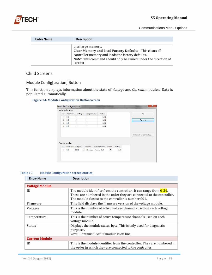
S5OperatingManual
Communications Menu Options
Ver.2.0(August2012) P a g e |52
Entry Name Description
dischargememory.ClearMemoryandLoadFactoryDefaults‐Thisclearsallcontrollermemoryandloadsthefactorydefaults.Note:ThiscommandshouldonlybeissuedunderthedirectionofBTECH.
Child Screens
Module Config[uration] Button
ThisfunctiondisplaysinformationaboutthestateofVoltageandCurrentmodules.Dataispopulatedautomatically.
Figure34‐ModuleConfigurationButtonScreen
Table10. ModuleConfigurationscreenentries
Entry Name Description
VoltageModuleID Themoduleidentifierfromthecontroller.Itcanrangefrom0‐24.
Thesearenumberedintheordertheyareconnectedtothecontroller.Themoduleclosesttothecontrollerisnumber001.
Firmware Thisfielddisplaysthefirmwareversionofthevoltagemodule.Voltages Thisisthenumberofactivevoltagechannelsusedoneachvoltage
module.Temperature Thisisthenumberofactivetemperaturechannelsusedoneach
voltagemodule.Status Displaysthemodulestatusbyte.Thisisonlyusedfordiagnostic
purposes.NOTE:Contains“0xff”ifmoduleisoffline.
CurrentModuleID Thisisthemoduleidentifierfromthecontroller.Theyarenumberedin
theorderinwhichtheyareconnectedtothecontroller.

S5OperatingManual
Communications Menu Options
Ver.2.0(August2012) P a g e |53
Entry Name Description
Firmware Thisfielddisplaysthefirmwareversionofthevoltagemodule.Multiplier TheMultiplierdeterminesthefullscalecurrentvaluebasedonthe
currenttransducer.SelectandchangethecurrentMultiplierby"double‐clicking"tohighlightthevalueandenteringanewnumber.Inthecaseofthecurrenttransducer,thisvalueisalsousedtodeterminethecurrentbasedonthenumberofcablesthatthecurrentclampgoesaround.
Direction Thisindicatesthedirectionofthecurrentclampusedwithinthesystem.NOTE:CheckthisboxONLYiftheclampisinstalledinreverse.
CurrentSensorLocation Thisisusedtoindicatewhetherthecurrentclampisinthepositivehalfornegativehalfofthestring.Clickthearrowwithinthefieldandselecttheproperoptionfromthedisplayedlist.
Status Displaysthemodulestatusbyte.Thisisonlyusedfordiagnosticpurposes.NOTE:Contains“0xff”ifmoduleisoff‐line.
Definition Block
Clickingthisbuttondisplaysadialogwheretheusercanvieworchangevariousoptionsthataresetthroughthedefinitionblock.
Figure35‐DefinitionBlockscreen
Table11. DefinitionBlockScreenContent
Entry Name Description
UnitNumberingNormal* Selectingthisradiobuttondisplaystheunitsshowninthehome
screenfrom1to‘n’beginningonthepositiveside.Reverse* Selectingthisradiobuttondisplaystheunitsshowninthehome
screenfrom‘n’to1beginningonthenegativeside.DialModem

S5OperatingManual
Communications Menu Options
Ver.2.0(August2012) P a g e |54
Entry Name Description
USAMode InternationalMode *seeBVMHomeScreenDisplayOptions,pg.128foradditionalinformation.
Figure36‐ThePassworddialog.
Discharge Setting Properties
Table12. DischargeSettingsProperties
Entry Name Description
DischargeTriggerLevelsCurrentTriggerLevel(Amps)
Thecurrentlevel,inamps,atwhichpointthecontrollerdeterminesabatterydischargeisoccurring.
CurrentResetLevel(Amps) Thecurrentlevel,inamps,atwhichpointthecontrollerdeterminesabatterydischargehasstopped.
VoltageTriggerLevel(Volts) IfaBVShasnocurrentmodule,itusesthesystemvoltagetodeterminewhenadischargeisoccurring.Whenthesystemvoltageisbelowthislevel,thecontrollerdeterminesadischargeisoccurring.NOTE:Becausethesystemvoltagedropatthebeginningofadischargeisnotinstantaneous,determiningdischargesismoreaccurateusingacurrenttransducer.
Figure37‐DischargeSettingsProperties
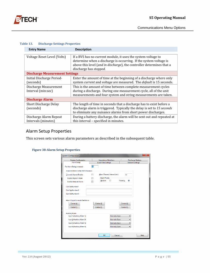
S5OperatingManual
Communications Menu Options
Ver.2.0(August2012) P a g e |55
Table13. DischargeSettingsProperties
Entry Name Description
VoltageResetLevel(Volts) IfaBVShasnocurrentmodule,itusesthesystemvoltagetodeterminewhenadischargeisoccurring.Ifthesystemvoltageisabovethislevel(andindischarge),thecontrollerdeterminesthatadischargehasstopped.
DischargeMeasurementSettingsInitialDischargePeriod‐(seconds)
Entertheamountoftimeatthebeginningofadischargewhereonlysystemcurrentandvoltagearemeasured.Thedefaultis15seconds.
DischargeMeasurementInterval(min:sec)
Thisistheamountoftimebetweencompletemeasurementcyclesduringadischarge.Duringonemeasurementcycle,alloftheunitmeasurementsandfoursystemandstringmeasurementsaretaken.
DischargeAlarmShortDischargeDelay(seconds)
Thelengthoftimeinsecondsthatadischargehastoexistbeforeadischargealarmistriggered.Typicallythedelayissetto15secondstoeliminateanynuisancealarmsfromshortpowerdischarges.
DischargeAlarmRepeatIntervals(minutes)
Duringabatterydischarge,thealarmwillbesentoutandrepeatedatthisinterval–specifiedinminutes.
Alarm Setup Properties
Thisscreensetsvariousalarmparametersasdescribedinthesubsequenttable.
Figure38‐AlarmSetupProperties

S5OperatingManual
Communications Menu Options
Ver.2.0(August2012) P a g e |56
Table14. SystemConfiguration:AlarmSetupPropertiesScreenContent
Entry Name Description
Re‐AlarmDelay‐(min) TheamountoftimetheBVSwaitsbeforere‐triggeringaspecificalarm.IfthesystemvoltageisoutoflimitsandtheAlarmDelayissetto1minute,theBVSwillgointoalarmmode,sendoutanalarm,beresetbytheBVSObserver,andwaitfor1minutebeforegoingbackintoalarmforsystemvoltage.
Transmit Alarms to the BVS Observer
TransmitAlarmEnable Whenthisboxischecked,alarmsareemailedoutaftertheyoccur.
AlarmResendInterval(min) Determinesthetimeintervalbeforeanactivealarmisre‐sent.AlarmPriority Checktheappropriatebuttontoindicatewhichalarmmode–
networkormodem–haspriority.Alarmsfortheselectedmodearesentoutfirst.Ifthealarmisnotreset,itresendsthealarmusingthenon‐prioritymode.
EnableModemAlarm Checkthisboxtohavealarmsdialedoutoveraphoneline.Enterthenumbertobedialedinthe"DialOut"field.Ifthisboxisnotchecked,noalarmsaredialedout.
EnableNetworkAlarm CheckthisboxtohavealarmstransmittedoveranIPnetworkconnectedtotheS5.
DialOutNumber1‐3 Thesefieldsareusedtoenterthephonenumber(s)todialiftheDialOutAlarmsoptionisenabled.Number1isdialedfirstand,ifthealarmisnotreset,theBVSproceedstodialNumber2andsoon.
Alarm Output Contacts Definition
Contact1‐6(below)
EachAlarmOutput[Relay]thatmaybeusedmustbeconfiguredseparately.WhenthebuttonforanyoftheContactsisclicked,theOutputAlarmDefinitionPropertiesSheetisdisplayed.
Auxiliary Inputs
AuxiliaryInputs1‐4 Defaultto“Open”butuserscanselectfromthedrop‐downlist.
Network Settings Properties
TheNetworkSettingsPropertiessheetisshownbelow.ItisonlynecessarytocompletethepropertyitemsiftheS5isbeingmonitoredoveraTCP/IPnetwork.
Information for the entries in this property sheet are generally provided by a network administrator.
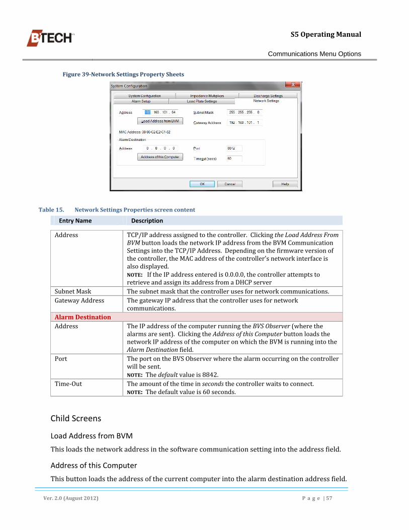
S5OperatingManual
Communications Menu Options
Ver.2.0(August2012) P a g e |57
Figure39‐NetworkSettingsPropertySheets
Table15. NetworkSettingsPropertiesscreencontent
Entry Name Description
Address TCP/IPaddressassignedtothecontroller.ClickingtheLoadAddressFromBVMbuttonloadsthenetworkIPaddressfromtheBVMCommunicationSettingsintotheTCP/IPAddress.Dependingonthefirmwareversionofthecontroller,theMACaddressofthecontroller'snetworkinterfaceisalsodisplayed.NOTE:IftheIPaddressenteredis0.0.0.0,thecontrollerattemptstoretrieveandassignitsaddressfromaDHCPserver
SubnetMask Thesubnetmaskthatthecontrollerusesfornetworkcommunications.GatewayAddress ThegatewayIPaddressthatthecontrollerusesfornetwork
communications.AlarmDestinationAddress TheIPaddressofthecomputerrunningtheBVSObserver(wherethe
alarmsaresent).ClickingtheAddressofthisComputerbuttonloadsthenetworkIPaddressofthecomputeronwhichtheBVMisrunningintotheAlarmDestinationfield.
Port TheportontheBVSObserverwherethealarmoccurringonthecontrollerwillbesent.NOTE:Thedefaultvalueis8842.
Time‐Out Theamountofthetimeinsecondsthecontrollerwaitstoconnect.NOTE:Thedefaultvalueis60seconds.
Child Screens
Load Address from BVM
Thisloadsthenetworkaddressinthesoftwarecommunicationsettingintotheaddressfield.
Address of this Computer
Thisbuttonloadstheaddressofthecurrentcomputerintothealarmdestinationaddressfield.

S5OperatingManual
Communications Menu Options
Ver.2.0(August2012) P a g e |58
Impedance Multipliers
Referto:ImpedanceMultipliers
ObtainingBaselineImpedanceValues
CertainparametersmustbesetoncethecomputerandtheS5controllerarecommunicating.ThisisdonefromvariousfunctionscontainedintheprimaryCommunicationsscreen.UtilizingthisscreentheusercanacquireabasesetofmeasurementsfromtheS5,savethemtotheS5’slocationfile,andstoretheminthecontrollermemory.
Table16. ImpedanceMultipliersTabProperties
Entry Name Description
Stringn–%PosHalf
Stringn–%NegHalf
Figure40‐ImpedanceMultipliersPropertySheet
Child Screens
Auto Multiplier Setup Manual Multiplier Setup
Referto“ImpedanceMultipliers
ObtainingBaselineImpedanceValues
CertainparametersmustbesetoncethecomputerandtheS5controllerarecommunicating.ThisisdonefromvariousfunctionscontainedintheprimaryCommunicationsscreen.Utilizingthis

S5OperatingManual
Communications Menu Options
Ver.2.0(August2012) P a g e |59
screentheusercanacquireabasesetofmeasurementsfromtheS5,savethemtotheS5’slocationfile,andstoretheminthecontrollermemory.
Load Plate Settings Properties
ThefollowingvaluesarethesystemvoltagelimitsbetweenwhichImpedancemeasurementsmaybetaken.Ifthesystemshowsmeasurementsthatareoutoftheselimits,noimpedancemeasurementscanbemadeandanalarmwillbegenerated.
These settings are determined by BTECH and are read only. They should only be changed by authorized personnel.
Figure41‐LoadPlateSettingsPropertySheet
Table17. LoadPlateProperties
Entry Name Description
Limits for Impedance Measurements
PositiveHalfMaxVoltageLimit
Not Available. Themaximumvoltagelimitforthepositivehalfofthebattery.
Positive Half Min Voltage Limit Not Available. Theminimumvoltagelimitforthepositivehalfofthebattery.
Negative Half Max Voltage Limit
Not Available. Themaximumvoltagelimitforthenegativehalfofthebattery.
Negative Half Min Voltage Limit
Not Available. Theminimumvoltagelimitforthenegativehalfofthebattery.
LoadPlateCurrent(RMS) NotAvailable.Theamountofloadcurrentdrawnbytheloadplate(dependsontheloadplatesuppliedwiththesystem).
SystemFullScaleVoltage NotAvailable.LoadPlateOffTime(sec) NotAvailable.SystemVoltageOffset NotAvailable.Thisvalueisusedbythecontrollertocompensate

S5OperatingManual
Communications Menu Options
Ver.2.0(August2012) P a g e |60
Entry Name Description
foranoffsetofthesystemvoltagemeasurementbytheloadplate.LoadPlateTempCutoff NotAvailable.Determinesunderwhattemperature,impedance
measurementscanbetaken.Thisistopreventtheloadplatefromoverheating.
ControllerSettings
WithintheControllerSettingsscreen,therearesixpropertytabpageswheresettingscanbemadeand/orviewed(seeFigure42).Themajorityofthesesettingsarecontrolleralarmlimits.
System Limits Properties
Figure42‐SystemLimitsPropertySheet
Table18. SystemLimitsPropertiesDescription
EntryName Description
MaxVoltage Themaximumallowedsystemvoltage.Ifthemeasuredvoltageisabovethisvalueitmayindicatethereisaproblemwiththecharger.
MinVoltage Theminimumallowedsystemvoltage.Ifthemeasuredvoltageisbelowthisvalueitmayindicatethereisaproblemwiththecharger,orthatthechargerisdisconnectedfromthebatteryorbatterystring.
MaxAmbient Themaximumallowedambienttemperature.MinAmbient Theminimumallowedambienttemperature.
Child Screens
Load BVM System Settings
Clickingthisbuttonloadsthesoftware'ssystemlimitsintotheappropriatefieldsandsyncsthehardwaresystemlimitstothesoftwaresystemlimits.Thereisnoscreenactivitywhenthisbuttonisclicked.

S5OperatingManual
Communications Menu Options
Ver.2.0(August2012) P a g e |61
Unit Limits Properties
TheUnit Limitsallowsthelimitsforeachunittobeselectedfromoneofthefoursetsoflimitsinthedrop‐down.Thesettingsalloweachindividualunittohavecustomconfiguredalarmlimits,(typicallyUnitLimitSet1isusedforallunits).
Figure43‐TheUnitLimitsPropertySheet
Table19. UnitLimitsPropertiesDescripton
Entry Name Description
String# Thestringnumber.Unit# Theunitnumberwithinthestring.UnitSettingsSet EnablestheusertoselecttheunitsettingsbasedonanotherStringand
Unitsettings.Impedance Analysis Drop‐down
ImpedanceAnalysisdrop‐down
Containstwooptions:Average–Averageimpedancelimitsarederivedfromtheaveragestringimpedance.Initial–theunitimpedancelimitsarecalculatedfroman‘initial’or‘baseline’impedancemeasurementtakenwhenthebatteryisknowntobehealthy.
Controller Measurement Setup Properties
Thecontrollermeasurementsheetallowstheday,time,andmeasurementfrequencytobeset.Therecommendedmeasurementintervalissevendays.Thefrequencyusedforperformingtheimpedancemeasurementisalsodisplayedandcannotbechanged.
Table20. ControllerMeasurementsSetupPropertiesDescription
EntryName Description
NextMeasurementDate(calendarbox)
Thedateofthenextmeasurement.
Time Thetimeofthenextmeasurement.

S5OperatingManual
Communications Menu Options
Ver.2.0(August2012) P a g e |62
EntryName Description
(spinbox)MeasurementIntervalDay(spinbox)
Thenumberofdaysbetweenmeasurements.
Hour(spinbox)
Onlyavailableifameasurementwillbetakenagaininlessthan24hours.
Figure44‐ControllerMeasurementSetupPropertySheet
Unit Limit Set [1‐4] Properties
Foursetsofalarmlimitsthatdefinewhenaunit'smeasurementisinanalarmstate.
All entered limits should correspond to limits recommended by the battery manufacturer for the particular make and model.
Figure45‐UnitLimitSetPropertySheet

S5OperatingManual
Communications Menu Options
Ver.2.0(August2012) P a g e |63
Table21. UnitLimitSet#PropertiesDescription
Entry Name Description
VoltageMaxMaintLimit Themaximummaintenancealarmlimit.MinLimit Theminimummaintenancealarmlimit.MaxCriticalLimit Themaximumcriticalalarmlimit.MinCriticalLimit Theminimumcriticalalarmlimits.ImpedanceMaint[enance]PercentLimit
Apercentagethatdeterminewhetheraunit'simpedanceisinamaintenancealarmstate.
PercentLimitCritical
Apercentagethatdeterminewhetheraunit'simpedanceisinacriticalalarmstate.
TemperatureMaxTempLimit Themaximumalarmlimit.MinTempLimit Theminimumalarmlimit.DifferentialLimit TheDifferentialLimitisthedifferenceintemperaturebetweentheambientand
unittemperature.
Child Screens
Load BVM Unit Settings
Thisbuttonloadsthesoftware'sunitlimitsforUnit1ofString1intotheappropriatefields,andsyncsthehardwareunitlimitstothesoftwareunitlimits.Thereisnoconfirmingdialog.
The Get/Set Configuration Option
ThisallowstheusertoextractandloadtheconfigurationandsettingsfromthecontrollertoBVM4.x.Extractingthememorytothefiledoesnotchangeanythinginthecontroller.However,loadingtheconfigurationfileintothecontrollerwilleraseallitsmemory.Everycontrollerisshippedfromthefactorywithafilecontainingitsconfigurationanddefaultsettings.TheuserwillalsobepromptedtoextractorloadtheInitialandInterconnectImpedancesvalues.
The Get/Set Controller Configuration dialog is critical to backing up, and restoring, the controller’s memory. This procedure should be performed prior to backing up the BVM4.x application and database files.
Figure46‐TheGet/SetControllerConfigurationdialog

S5OperatingManual
Communications Menu Options
Ver.2.0(August2012) P a g e |64
Extracting Controller Data to the Software
Controllerdatacontentcanbeextractedperiodicallyandsenttoalocationfile.Usethefollowingprocedure.
a. NavigatetotheCommunicationsmainscreenandexpanditbyclickingAdvanced,(seeFigure31,pg,48),
b. ClicktheGet/SetControllerConfigurationbutton,(seeabove),c. Intheresultingdialog(seeabove),selecttheExtractradiobuttonandclickOK,d. Intheresultingdialogselectthefileandlocation(mustbea.setfile)wherethedatawillbe
savedandclickSave,e. ClickYeswhenpromptedtosavetheInitialandInterconnectmeasurementvaluesifthe
datawillberetained.
Restoring Controller Data from BVM4.x Using Load
UsingtheGet/SetControllerConfigurationbutton,datafroma.setfilecanbedownloadedtotheS5controller.Generallythisisdonetorestorecontrollersettingsthathavebecomecorruptorotherwiseunreliable.Torestoredatausethefollowingprocedure.
a. NavigatetotheCommunicationsmainscreenandexpanditbyclickingAdvanced,b. ClicktheGet/SetControllerConfigurationbutton,(seeFigure31,pg.48),c. Intheresultingdialog(seeabove),selecttheLoadradiobuttonandclickOK,d. Intheresultingdialogselectthedesired.setfileandclickOK.Thisloadsthedatafromthe
selectedfile. NOTE:Inmostcasesthemostrecentdatawillberestored,howeveranyavailabledatafile
canbeusedforthe‘restore’.
ClickYeswhenpromptedtoloadtheInitialandInterconnectmeasurementvalues,
TheRebootOption
ThisbuttonrebootstheS5.Thereisnospecificscreenforrebootingbutaconfirmationdialogisdisplayedwheretheusercanproceedorcanceltheaction(seeFigure31,pg.48).
TheStandbyOption
Thisbuttonfunctionsasatoggleandismostoftenusedtoperformworkonthebatterystring.PlacingthebatterymonitorinStandbypreventsclosureoftherelaysthatconnectthebatterystringtothebatterymonitor.Thispreventsthebatterymonitorfromalarmingforanyout‐of‐limitsconditions,aswellasprotectingpersonnelandequipment.Usethefollowingprocedure.
a. ClicktheStandbybuttonandthestatusindicatorinthewindowindicatesthemonitorisbeingplacedinstandbymode. theStandbybuttontextchangesto“ExitStandby”.
b. ToexitStandbymodeclicktheExitStandbybutton.

S5OperatingManual
Communications Menu Options
Ver.2.0(August2012) P a g e |65
theStandbybuttontextchangesto“Standby”.
TheInterconnectImpedanceDrop‐down
Theunitinterconnectimpedancevaluesareusedtoadjustindividualunitimpedancemeasurementswheretherearedifferentlengthinterconnectsthanusedontherestofthebattery.Thedrop‐downcontainsthefollowingoptions(seeFigure31,pg.48).
“RetrieveInterconnectImpedanceValuesfromControllerandSavetoBVMSoftware”
Thisoptionretrievesthecurrentinterconnectimpedancevaluesandwritesthemtothelocationfile.
a. ClickontheInitialImpedancedrop‐downandselect‘RetrieveInterconnectImpedance...’
b. InthepreviewdatascreenclickOK,c. ClickOKinthewarningdialog.
“LoadInterconnectImpedanceValuestoControllerfromBVMSoftware”
ThisoptionreadstheinterconnectvalesfromthelocationfileandwritesthemtotheS5controller.
Figure47‐InterconnectImpedanceOptions
InitialImpedanceDrop‐downOptions
Theoptionslistedinthisdrop‐downfunctionareusedtoretrieveinitialimpedancevaluesfromthebatteries.ThedatacanthenbesavedtotheBVMdatabaseand/orbewrittentothecontroller’smemory.Theoptionsaregenerallyusedduringtheinitialconfigurationofanewsite,orwhenmajorchangesaremadetotheconfigurationofanexistingsite.RefertoFigure48,onpage66.
Create Initial Impedance Measurements in Controller
Thisfunctioncausesthecontrollertoperformanewimpedancemeasurement.Theimpedancedataisrecordedforeachunitduringthismeasurementandisusedasthenew"InitialImpedance"data.Theuserisalertedandpromptedthatperformingthisactionwilloverwritetheinitialimpedanceinformationstoredinthecontroller.Afterthisoperationhasiscompleted,theuser

S5OperatingManual
Communications Menu Options
Ver.2.0(August2012) P a g e |66
shouldperformthe"RetrieveInitialImpedanceMeasurementsFromControllerandSavetoBVMSoftwareUnitSettings"commandtoretrievetheinitialimpedancemeasurements.
a. Clickthedrop‐downandselectthisoptionfromthelist,b. SelectthecurrentdateinthedatedialogandclickOK,c. ClickYesinthewarningdialog.
Retrieve Initial Impedance Measurements from Controller and Save to BVM Software Unit Settings
Thisretrievestheinitialimpedancemeasurementsfromthecontrollerandshowsthemtotheuser.Thisallowstheusertopreviewtheinformationbeforemakinganychanges.ItthenpromptstheusertooverwriteanyexistinginitialimpedancemeasurementsintheUnitSettings.Iftheyagree,itsavestheinitialimpedancemeasurementstotheUnitSettings.
a. ClicktheInitialImpedancedrop‐downandselect‘RetrieveInitialImpedance...’b. InthepreviewdatascreenconfirmthatTBAandclickOK,c. ClickOKinthewarningdialog.
Figure48‐InitialImpedanceDrop‐downOptions
Load Initial Impedance Measurements to the Controller from BVM Software Unit Settings
Thisloadsthecontroller'sinitialimpedancememorywiththeinitialmeasurementsstoredintheBVM'sUnitSettings.Theuserisalertedandpromptedthatperformingthisactionwilloverwritetheinitialimpedanceinformationstoredinthecontroller.
a. ClicktheInitialImpedancedrop‐downandselect‘LoadInitialImpedanceMeasurements...’,b. ClickYesinthedialog.

S5OperatingManual
Equipment Checks and Troubleshooting
Ver.2.0(August2012) P a g e |67
6. Equipment Checks and Troubleshooting
BTECHprovidesacomplete,customwirelistandinstalldiagram(s)thatspecifiesthepositionandconnectionsforallcomponents.IfthisdiagramisnotavailablecontactBTECHforaduplicate.Ifathoroughcheckofallcomponentconnectionsdoesnotresolvependingissues,checkthecomponentsandconnectionstotheBTECH‐provideddiagram(s).
Battery Connections
Iftabwashersareused,verifythattheyarecorrectlyinstalledtothecellterminalboltornut;andincompliancewiththewiringdiagram.Tabsshouldbefacinginanappropriatedirectionforcorrectwirerouting(seeRoutingVSLandLCLWiring,beginningonpg.68).Ifthecellhas3pairsofposts,tabwashershouldbeinstalledunderthemiddlecellterminalboltifpossible.
WheretheVSLandLCLPigtailsconnecttobatteryterminalsusingaTabwasherconfirmthefollowing:
Tabwashersandrelatedhardwareareproperlyconnectedtobatteryterminalsasshownbelow(A&B),
Thefemaleendofthepigtailissecurlyconnectedtothetabwasher,(C)
Figure49:TabWashersmountedDirectlytoBatteries(A&B);VSLPigtailconnectionusingaTabwasher(C),

S5OperatingManual
Equipment Checks and Troubleshooting
Ver.2.0(August2012) P a g e |68
Stainless Steel Clamps
Forinstallationswheretheconnectionaremadetobatterystraps,BTECHincludesetsofstainlesssteelclampswiththepigtailassembledtotheclamp.Actualpositioningoftheclamp(s)onthebatterystrapsisdeterminedbythesystemwiringdiagram.Verifythattheclampsarepositionedasclosetocellpostaspractical.Ifthecellhasthreepairsofposts,clampshouldbenearthemiddlepostifpossible.
Confirmthattheclampsaresecurlyattachedtothebatterystraps.
Figure50‐AttachingStainlessSteelClampstobatterystraps
TheLCLandVSLWires
TheVSLwiresmustbesecuredintheappropriate10‐and16‐pinWago™connectorsandterminatedtotheVM‐24iunit.Additionally,theLCLwiresmustbesecuredina4‐pinscrewconnectorandterminatedtotheS5.Thepathusedtoroutethewiresandtheconduit(ifused)throughwhichthewirespass,mustbeinstalledcorrectlyorerroneousreadingsmayresult,(seeFigure51below).
Routing VSL and LCL Wiring
ThefollowingpracticesshouldbeobservedforVSLandLCLwirerouting.

S5OperatingManual
Equipment Checks and Troubleshooting
Ver.2.0(August2012) P a g e |69
ConfirmthattheVSLwiringisroutedalongthecurrentpath.
WiringductsmountedonbatteryracksareinstalledontheINSIDEoftherack.
WheneverVSLandLCLlinesareroutedinparallel,theyMUSTbeseparatedbyaminimumof2feet,(61cm).
WheneverVSLandLCLwiringcross–theyMUSTdosoatrightangles.
VSLandLCLlinesmustberoutedinseparatechannelsorconduits.
CommunicationcablesMUSTberoutedseparatelyfromVSLandLCLwiring.
Figure51‐VSL‐LCLWiringDiagrams
Connecting S5 and VM‐24i Units
Single Unit Connections
Confirmthatthefollowingconditionshavebeenmet,(seeFigure52,pg.70).
The‘White’connectorissecurlypluggedintothethebackoftheS5unitandthe‘Orange’connectorispluggedintotheINportoftheVM‐24i.
TheBTECH‐provided‘CommunicationTerminationplugiscorrectlypositionedandsecurlypluggedintotheOUTportoftheVM‐24i.
DO NOT attempt to use the S5 system without the Termination Plug in place.
Daisy-chained VM-24i Unit Connections
VM‐24iunitsaredaisy‐chainedinanS5systemusing‘Communication’cables.Confirmthefollowingconnectionshavebeenmade.
The‘White’connectorissecurlypluggedintothethebackoftheS5,andthe‘Orange’connectorispluggedintotheINportofthefirstVM‐24i(seeFigure52,pg.70).

S5OperatingManual
Equipment Checks and Troubleshooting
Ver.2.0(August2012) P a g e |70
The‘White’connectorispluggedintothe‘OUT’portofthefirstVM‐24i,andthe‘Orange’connectorispluggedintotheINportofthenextVM‐24i.
Continuethisprocessuntilthelastdaisy‐chainedVM‐24iisconnectedusingtheBTECH‐provided‘CommunicationTerminationplugintotheOUTport(seebelow).
Theterminationplugshouldbeusedasdescribedinthisguide.DONOTinsertanywiresintotheplug.
Figure52‐Daisy‐chainedVM‐24iunits.ThelastunitMUSThavethe‘terminationpluginstalled
CurrentTransducerConnections
CurrentTransducers(CTs)areshippedbyBTECHterminatedtothe4‐pinconnector.ConfirmthattheCTsarecorrectlyinstalled.
TheCTsareinstalledaroundthe‘BatteryCharging’cablesothatthereddotfacesthepositivesideoftheUPS(uninterruptablepowersupply).
TheCTcableissecurlypluggedintotheVM‐24i.
TheserialnumberoneachCTiscorrectlymatchedtothecorrespondingVM‐24i(seebelow).
Thegreenplugofthecurrenttransduceriscorrectlyinsertedintotheleft‐sideoftheeight‐pinconnector.

S5OperatingManual
Equipment Checks and Troubleshooting
Ver.2.0(August2012) P a g e |71
Figure53‐MatchingserialnumbersbetweenaCTandS5
BatteryTopTemperatureSensors(Thermistors)
ThermistorsarenotarequiredcomponentofanS5monitoringsystem.Iftheyareused,thefollowingitemsshouldbechecked.
Thesensorshouldbepositionedadjascenttotherackorcabinetcontainingthebatteryunit: Rack Mounted batteries – install near battery strings.
Cabinet Configurations – install inside the cabinet approximately 3/4 of the distance to the cabinet bottom.
The2‐pinconnectorshouldbefirmlyinsertedintothedesignatedportontheS5mid‐panel.(seeFigure55,pg.73).
Thermistors installed to measure ambient temperatures must be placed away from heating or cooling sources to prevent erroneous readings.
S5GroundConnections
OnceallwireshavebeenterminatedtothecorrectmoduletheS5systemMUSTbegrounded.
The SCM‐600 should NOT be connected to a power source until grounding is complete.
Ground the S5
TheS5systemmustbegroundedbeforepowerisapplied.Confirmthatthefollowingconditionexists.
ThegroundwiretipissecuredtotheGnDconectoronthemid‐paneloftheS5(seeFigure55,pg.73).
TheBTECHsupplied3/8inch(9.5mm)connectingringorsimilardeviceisattachedtotheoppositeendofthewireandsecuredtoagroundingpointontherackorcabinet(seebelow).

S5OperatingManual
Equipment Checks and Troubleshooting
Ver.2.0(August2012) P a g e |72
The S5 System MUST be properly grounded as described in this section or damage to the system and voiding of the warranty may result.
Figure54–S5GroundingExample
FusesandtoPowerSourceConnections
TheinlinefusesforalloftheLCLandVSLpigtailsmustbecorrectlyinstalled.BTECHprovidesallofthefusesrequiredfortheS5system.Confirmthefollowingconditionsaremet.
Allpigtailshavethecorrectfuseinplace, For VSL leads BTECH supplies 62 Ma fuses,
For LCL leads BTECH provides ATM fuses.
TheleadsfromtheVSLandLCLpigtailarecorrectlypairedwiththecorrespondingleadfromtheS5orVM‐24iasspecifiedinthewiringdiagram.
Thehalvesofthefuseholdersaresecurlyconnected.
Checking Fuses
Wheninstallingorinspectingfusesthefollowingpracticesshouldalwaysbeobserved.
InsertthefuseintothefuseholderattachedtotheleadterminatingattheVM‐24iortheS5.Matethetwohalvesofthefuseholderandrotateclockwiseuntilthetwosectionsareconnected.Rotatecounter‐clockwisetoseparatethefuseholderhalves.
Always insert the fuse in section of the fuse holder attached to the lead that terminates at the VM‐24i unit. DO NOT insert the fuse into the section of the fuse holder for the pigtail attached to the battery.
Do NOT use fuses of a different power rating then the ones provided or damage to the system and voiding of the warranty may result.
Do NOT connect the S5 to a power source until ALL fuses have been installed. Always disconnect the S5 from its power source before inspecting fuses.

S5OperatingManual
Equipment Checks and Troubleshooting
Ver.2.0(August2012) P a g e |73
Figure55–S5Mid‐panelshowingwithcertainconnectionsLabeled

S5OperatingManual
Equipment Checks and Troubleshooting
Ver.2.0(August2012) P a g e |74
InstallationCheckList
Thissectioncontainsanchecklistfortheinstallertorecordequipment,communication,andconfigurationinformationforaparticularcustomerS5site.TheformshouldbecompletedandsignedbythecustomerandforwardedtotheBTECHhomeoffice.
ThissectioncanbeprintedbyclickingPrintandentering“S9”(noquotes)inthe‘Pages”fieldontheWindowsPrintdialog,(seebelow).TheformcanbecopiedandpastedandcompletedusingMicrosoftWord.
Figure56‐TheWin7PrintDialog

S5OperatingManual
Equipment Checks and Troubleshooting
Ver.2.0(August2012) P a g e |75
S5StartupCheckList
Customer Location
Date:
BVS M/N BVS Serial # System #/ID
VM‐24i‐CT Serial # Installed Around String Cables CAL Code
of
of
of
of
of
of
of
of
A. Installation,Inspection,andConfirmation
YES NO
1 Was there any shipping damage? If YES describe
2 Was the BVS wired completely and according to instructions? (Was this a BTECH install?)
Describe Acceptable Unacceptable
3 Was enclosure clean and free of metal chips and filings?
4 Is a ground wire correctly installed (chassis ground lug to battery rack\cabinet)?
5 Are power and communications (if required) installed and active?
Power
Communications
6 Is ambient temp. installed away from heating or cooling air ducts?
Installed Location:
7 A. Do the serial numbers of the current clamps and CM‐2/VM‐24i modules match?
B. CT is around of battery cables. Multiplier is:
8 Were pilot cell thermistors correctly installed?
Record jar numbers on attached form

S5OperatingManual
Equipment Checks and Troubleshooting
Ver.2.0(August2012) P a g e |76
YES NO
9 Was wiring between cells and VM‐24s terminated and routed correctly?
10 Were the VSL fuses installed?
11 Was Comm. wiring between modules terminated correctly (color code and order)?
12 Was Comm. wiring damaged in any way?
13 Were the Load Leads (LCL) correctly routed and terminated?
14 Are all LCL fuses installed? Confirm the fuse rating matches the load plate current.
15 Confirm the load lead terminal voltage matches the split as designed. Correct as required.
16 Confirm that the BVS is powered according to design. (DC Powered)
17 Is the single Comm. cable terminator installed at last 24i?
B. OperationVerification
After section “A” is complete, power can be applied to the BVS S5. Turn on both switches.
YES NO
1 Confirm that the number of modules matches the configuration of the .set file.
2 Is an inline power delay module in use?
Measure and record the voltage supplied to the last module. (Min. acceptable is 18 VDC).
3 Use Module diagnostics to confirm that the number of units and Thermistors connected to each VM‐24i matches the module configuration. Correct module configuration as required.
4 Run Relearn Connections. Did the S5 learn the system correctly? If NO explain modifications that were made.
5 Confirm installation of the current clamps (polarity and number of cables).
6 Confirm that the multiplier in the module configuration matches the physical configuration as recorded in Sect A‐7A (above). Change the CM‐2/VM‐24i as necessary.
7 Is the voltage to the current clamp 5 VDC (red to black) and 2.5 VDC (white to black)?
8 Was current clamp operation verified, (disconnect the CT cable in real‐time mode)?
9 Was VSL wiring and Comm. wiring verified by removing VSL fuses (one per Voltage Module towards one end) while watching real‐time unit voltage graph?
10 Where the impedance multipliers set? Check one. Auto is for even split ONLY.
Manual setup Automatic setup
11 Are any interconnect impedance values set? If YES load values into SCM.
12 Did the S5 perform a complete measurement?
If NO – explain.
13 Download alarms, measurements, and discharge data. If setup and alarms are in BVS memory – clear memory and delete alarms and measurements from memory.
14 Were successive impedance measurements consistent?

S5OperatingManual
Equipment Checks and Troubleshooting
Ver.2.0(August2012) P a g e |77
YES NO
15 Confirm the Unit and System Analysis and Reports do not generate false alarms. Correct as required.
16 BVS S5 (and BVM 4.x) was left in which impedance mode?
Average Initial
17 Are Communication available?
Type: Modem phone # Network: Gateway IP: Subnet Mask:
18 If modem connection is used: A. Check communication with ring emulator if no permanent line installed. B. Dial out prefix (circle one): 9 8 C. Dial “1” and/or 10 digits
Use analog phone to dial cell number.
Use BVM to dial alarm out to cell number.
19 Next read date and time and interval per customer agreement.
Date: Time: Interval: (hours or days)
20 Extract .set file (as left) and label with: “As left”, “Date:”.
21 Obtain copy of BVM files.
22 Controller and TCP firmware version as left.
Controller: TCP:
23 Is the BVS fully operational per Operations Manual procedures?
C.CustomerComputerSetup
YES NO
1 A. Was software installed and configured?
B. Did it operate correctly? Software ver. BVM PC OS:
2 If required was USB driver installed?
3 Confirm two‐way communication for all installed options.
4 Download data from controller saved in the customer’s PC data directory
5 Is the .set file, as currently loaded in the SCM‐600, saved in the customer’s data directory?
6 Was a custom battery map prepared? (standard is to complete this on site).
7 Were Thermistors mapped? (standard is to map shelves/groups to a single Thermistor).
8 Obtain a copy of BVM files as left on customer’s computer.
9 Is BVM 4.x and Observer fully operational per Operating Manual procedures?
10 Describe planned repair work:

S5OperatingManual
Equipment Checks and Troubleshooting
Ver.2.0(August2012) P a g e |78
YES NO
D.CustomerSignoff
Customer Date
BTECH Rep. Date
Additional Comments and Information:
Post‐Startup/ServiceReport
Site Date
BTECH Personnel Serial #
List ALL changes made at Startup
List ALL follow‐up issues
Items that need to be shipped to customer
Item Cost Date Shipped

S5OperatingManual
Equipment Checks and Troubleshooting
Ver.2.0(August2012) P a g e |79
Items that need to be returned from customer
Item Date Received
Contact 1 Contact 2
Name: Name:
Address:
Address:
Off. Phone/Ext: Off. Phone/Ext:
Cell: Cell:
FAX: FAX:
Email: Email:
Thermistor Mapping
VM 24i VM 24i
1 2
3 4
5 6
7 8
9 10
11 12
13 14
15 16
17 18
19 20

S5OperatingManual
Reports
Ver.2.0(August2012) P a g e |80
7. Reports BVMsoftwareincorporatesbasereportformatsforanumberofparametersthatitrecordsandtrends.Dependingontheparticularmeasurementtheusermustprovideaspecifieddate,and/oradaterangeandtime.
GeneralInformation
Thecolumnsonmostreportscanbeexpandedorcondensedbyplacingthecursoronthecolumnborderintheheadingrowanddraggingtheborderrightorleft.Whenplacedontheborderthecursorchangestoadouble‐pointedarrow(seeFigure60,pg.83).
Datacanbedeletedfromthereport.
Exporting Data
Thedatafrommostreportscanbeexportedin.csvformatbyselectingFile>ExportDatainthemenubar.Asubmenuofoptionsisdisplayed.Formatsforexporteddatawillvary.
Date-Time Parameters
Manyreportsrequiretheusertosetorenterone,orapairofdates.Generallythisisdoneinacalendarspinbox.Ifnodateisavailableitmeansnodataiscurrentlyavailableforthatdate.
Figure57‐Acceptorchangethedateorthedaterangeforareport.
String/Unit Parameters
Somereportscanberestrictedtoaparticularstringand/orunitbyselectingtheminthetoolbar.Thedefaultis‘AllStringsandUnits’.UserscanalsodisplaydataforVoltage,Impedance,Current,orTemperaturebyselectingtheappropriateiconinthetoolbar.

S5OperatingManual
Reports
Ver.2.0(August2012) P a g e |81
Figure58‐SelectingStringsand/orUnitsforReports
If an icon is grayed out (unavailable) it cannot be used for the report type selected from the menu or side bar.
Sorting Report Data
Datafromsome–butnotall–reportscanbesortedbyclickingonthecolumntitleoronasortarrowinthetitlerow(seeFigure61,page84).It’spossibletosortreportdataonmultiplecolumnsbutonlyonecolumncanbesortedatatime.
Highlighted Data
Manyreportsdisplaydatarowentrieshighlightedinredoryellowifthedataisoutsideofnormalparameters(seeFigure63,pg.86).
Printing Reports
Some–butnotall–reportscanbeprintedfromtheFilemenuinthemenubar.IfthePrintoptionisunavailable(grayedout)inthemenulistthedatamustbeexportedtoanotherapplicationtobeprinted.
Dual Report Sources
Somereportscanbegeneratedfrommultiplesources(typicallytheHomescreensidebarandtheReportsorViewmenu).Itmakesnodifferencewhichsourceisused.Theindividualreportdescriptionsinthissectiondescribeallsourcesforaparticularreport.
BVMHomeScreenSideBarReports
ThesidepaneloftheHomescreenprovidesalistofreportsandgraphsthatBVMcangenerate(see,page16).AllsidebarreportsarealsoavailablefromReportsinthemenubar.
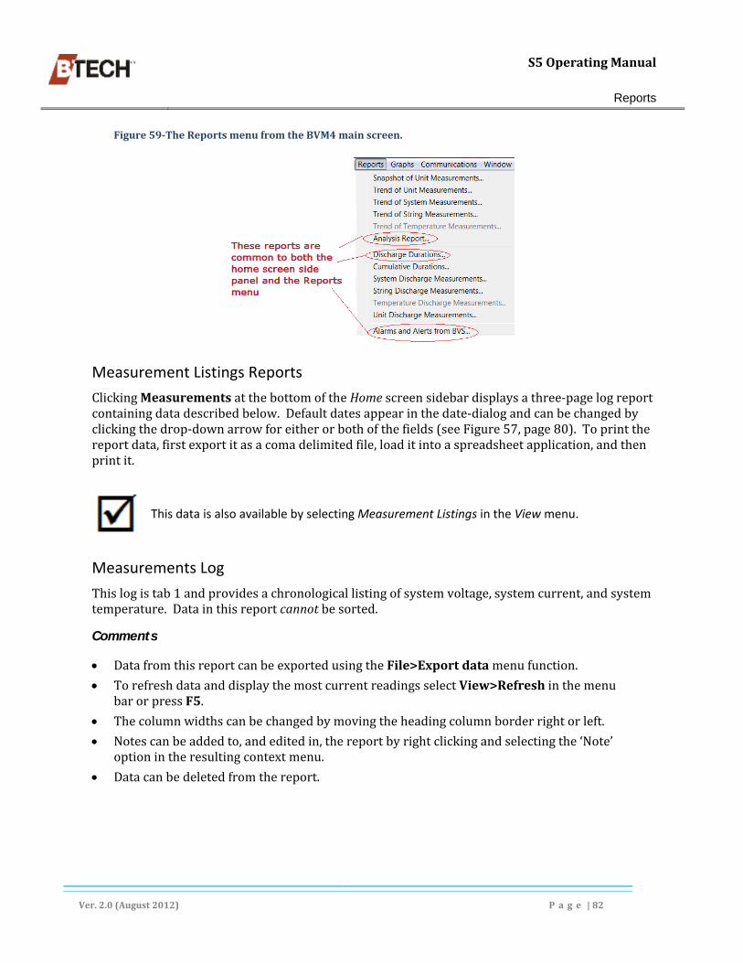
S5OperatingManual
Reports
Ver.2.0(August2012) P a g e |82
Figure59‐TheReportsmenufromtheBVM4mainscreen.
Measurement Listings Reports
ClickingMeasurementsatthebottomoftheHomescreensidebardisplaysathree‐pagelogreportcontainingdatadescribedbelow.Defaultdatesappearinthedate‐dialogandcanbechangedbyclickingthedrop‐downarrowforeitherorbothofthefields(seeFigure57,page80).Toprintthereportdata,firstexportitasacomadelimitedfile,loaditintoaspreadsheetapplication,andthenprintit.
This data is also available by selecting Measurement Listings in the View menu.
Measurements Log
Thislogistab1andprovidesachronologicallistingofsystemvoltage,systemcurrent,andsystemtemperature.Datainthisreportcannotbesorted.
Comments
DatafromthisreportcanbeexportedusingtheFile>Exportdatamenufunction.
TorefreshdataanddisplaythemostcurrentreadingsselectView>RefreshinthemenubarorpressF5.
Thecolumnwidthscanbechangedbymovingtheheadingcolumnborderrightorleft.
Notescanbeaddedto,andeditedin,thereportbyrightclickingandselectingthe‘Note’optionintheresultingcontextmenu.
Datacanbedeletedfromthereport.

S5OperatingManual
Reports
Ver.2.0(August2012) P a g e |83
Figure60‐TheMeasurementsLog–Measurementstab
Discharge Intervals Logs
Thisreportistabtwoandisformattedastwoseparatetables.Itprovidesdateanddurationdataforanydischargeperiodsoccurringduringthecoveredperiod,(i.e.anyperiodsthatpowerwassuppliedfromthebatterysourceratherthanthepowergrid).Thetoppaneltabledischargestartdate,time,andduration;thebottomtabledisplayssystemdischargecurrent,systemvoltage,andambienttemperature.
Comments
Discharges:SelectingarowintheDischargeslog(toptable)determinesthedetaildatadisplayedintheSystemDischargelog,(bottomtable).
DatacontainedinthereportlogscanbeexportedusingtheFile>Exportoptioninthemenubar.
Thecolumnwidthscanbechangedbymovingtheheadingcolumnborderrightorleft.
Notescanbeaddedto,andedited,inthereport.
Datacanbedeletedfromthereport.
Reportcolumnscanbeexpandedorcondensedbydraggingthecolumnborderleftorright.
Right‐clickinginthelogscreendisplaysacontextmenu.Select“EditMeasurementNote”

S5OperatingManual
Reports
Ver.2.0(August2012) P a g e |84
Figure61‐DischargeandSystemDischargeMeasurementLogs
Alarms and Alerts Tab Log
Thisreport(calledthe“AlertsandAlarmsfromBVS”intheReportsmenu)providesdate‐time,andtypeofalertoralarmduringthespecifiedperiod.Italsoreflectsactionstakenbytheindividualsitestaffandrecordstheidentityofthestaffmemberupdatingthelogentry.
Alarms and alerts can be acknowledged in this page. See Acknowledging Alarms and Alerts , pg. 28.
DatafromthisreportcanbeexportedusingtheFile>Exportdatamenufunction.
Thecolumnwidthscanbechangedbymovingtheheadingcolumnborderrightorleft.
Notescanbeaddedto,andedited,thereport.
Figure62‐TheAlarmsandAlertsLogs(partialillustration)

S5OperatingManual
Reports
Ver.2.0(August2012) P a g e |85
SideBarReports
Thesebuttonsareshortcutstothemostcommonlyusedreports.Eachofthereportsisalsoavailableunderneath“Reports”inthemenubar.
System Analysis Report
Thisreport,(calledthe“AnalysisReport”intheReportssub‐menu)requirestheusertoselectadate/time.Itshowsavarietyofstatisticalinformationaboutthevoltage,impedance,andtemperaturedatagatheredduringameasurement.Anotherresultoftheanalysisisalistoftheunitmeasurementsthatareout‐of‐limits.Dependingontheselection,eitherallunitscanbeshownorjusttheout‐of‐limits.
Comments
Thecolumnwidthscanbechangedbymovingtheheadingcolumnborderrightorleft.
DatafromthisreportcanbeexportedusingtheFile>Exportdatamenufunction.
DatafromthisreportcanbeprintedusingtheFile>Printmenufunction.
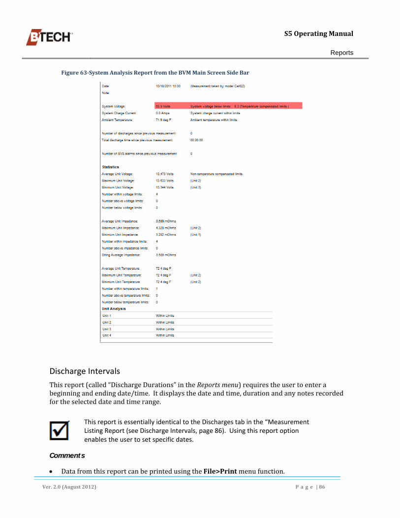
S5OperatingManual
Reports
Ver.2.0(August2012) P a g e |86
Figure63‐SystemAnalysisReportfromtheBVMMainScreenSideBar
Discharge Intervals
Thisreport(called“DischargeDurations”intheReportsmenu)requirestheusertoenterabeginningandendingdate/time.Itdisplaysthedateandtime,durationandanynotesrecordedfortheselecteddateandtimerange.
This report is essentially identical to the Discharges tab in the “Measurement Listing Report (see Discharge Intervals, page 86). Using this report option enables the user to set specific dates.
Comments
DatafromthisreportcanbeprintedusingtheFile>Printmenufunction.

S5OperatingManual
Reports
Ver.2.0(August2012) P a g e |87
DatafromthisreportcanbeexportedusingtheFile>Exportdatamenufunction.
Reportdatacanbesortedbyclickingthearrowinthecolumnheading.
Figure64‐DischargeIntervals(Homescreensidebar–partialillustration)
Alerts and Alarms Report
Thisreportdisplaysthedate,time,andadescriptionofanyalertsreceivedfromtheBVS overthestipulatedrange.Anynotesaddedtoanalertbyauserarealsoshown.Thedateandtimethealarmwasacknowledgedbytheuserwillalsobeshown.Ifthealarmstatewasresolved,(e.g.atemperaturereturningtowithinlimits),thedateandtimearealsoshown.
This report is essentially identical to the Alarms and Alerts tab in the “Measurement Listing Report (see Alerts and Alarms Report, page 87). Using this report option enables the user to set specific dates.
Comments
DatafromthisreportcanbeprintedusingtheFile>Printmenufunction.
DatafromthisreportcanbeexportedusingtheFile>Exportdatamenufunction.
Reportdatacanbesortedbyclickingthearrowinthecolumnheading.
Right‐clickinginthereportscreendisplaysapopupmenu(describedbelow).
Figure65‐AlertsandAlarms,Sidebar(partialillustration)

S5OperatingManual
Reports
Ver.2.0(August2012) P a g e |88
Filter and Sort Alarms and Alerts
Thisfunctionalityisavailablefromthereport’spopupmenu.Itenablestheusertobroadenorrestrictthereportresultsaccordingtoselectedcriteria.Italsoallowssortcriteriatobedefined.
Figure66‐AlarmsandAlertsFilterscreen
ReportsMenu
AnextensivenumberofadditionalreportsarefoundundertheReportsmenu.AspreviouslynotedsomeitemsareavailableintheHomescreensidebarandwillnotberepeatedhere.
Whenmostreportsareselectedadatedialogboxisdisplayed(seeFigure57,page80).Forsomereportstheusermustenteradateandtimerange(oracceptthedefault).Inothercasesonlyasingledateisnecessary.
If no date(s) appear in the drop‐down box no data is available for the report.
Snapshot of Unit Measurements
Thisreportdisplaysallthevoltage,impedance,andtemperaturemeasurementstakenduringonereadoftheBVS.Anyunitswithmeasurementsexceedingthemaintenancelimitsarehighlightedinyellowwhilethoseexceedingthecriticallimitsareshowninred.Themeasurement(s)(voltage,impedance,ortemperature)causingtheout‐of‐limitsconditionaredisplayedinbold.
Comments
DatafromthisreportcanbeprintedusingtheFile>Printmenufunction.
DatafromthisreportcanbeexportedusingtheFile>Exportdatamenufunction.

S5OperatingManual
Reports
Ver.2.0(August2012) P a g e |89
Userscanmovethereportdatebackwardorforwardbyright‐clickinginthereportscreenandmakingtheappropriateselectioninthepopupmenu(seebelow–inset).
Datacanbesortedbyclickingthearrowintheheadingrow.
Figure67‐SnapshotofUnitMeasurementsReportExample(partialillustration)
Trend of System Measurements Report
Thisreportrequirestheusertoenterabeginningandendingdate/time.Itshowsthesystem'svoltage,chargecurrent,averageunit temp,andambienttempoverthedateandtimeselected.Anymeasurementsexceedingthelimitsareshowninyelloworred.Themeasurement(s)(voltage,current,ortemperature)causingtheout‐of‐limitsconditionaredisplayedinbold.
Comments
Themeasurementscanbesortedbyclickingonthearrowinthetopofeachcolumn.
DatafromthisreportcanbeprintedusingtheFile>Printmenufunction.
DatafromthisreportcanbeexportedusingtheFile>Exportdatamenufunction.
Figure68‐TrendofSystemMeasurementsReport(partialillustration)
Trend of Unit Measurements Report
Thisreportrequirestheusertoenterabeginningandendingdate/time.Itshowsdataforoneunit’svoltage,impedance,andtemperaturemeasurementsoverthedateandtimeselected.Anymeasurementsexceedingmaintenancelimitsarehighlightedinyellowwhilethoseexceeding

S5OperatingManual
Reports
Ver.2.0(August2012) P a g e |90
criticallimitsareshowninred.Themeasurement(s)(voltage,impedance,ortemperature)causingtheout‐of‐limitsconditionisdisplayedinbold.
Comments
DatafromthisreportcanbeprintedusingtheFile>Printmenufunction.
Userscanmovetheselectedunitbackwardorforward,orselectitdirectlybyright‐clickinginthereportscreenandmakingtheappropriateselectioninthepopupmenu(seebelow–inset).
DatafromthisreportcanbeexportedusingtheFile>Exportdatamenufunction.
Themeasurementscanbesortedbyclickingonthearrowinthetopofeachcolumn.
Figure69‐TrendofUnitMeasurementReport(partialillustration)
Trend of String Measurements Report
Thisreportrequirestheusertoenterabeginningandendingdate/time.Itshowsoneormorestring'schargecurrentspanningthedateandtimeselected.Withthelatestfirmware,thereportswillalsoshowtheindividualstringvoltages.Anycurrentmeasurementsexceedingthestringchargecurrentlimitorvoltagemeasurementsoutsidethevoltagelimitsarehighlightedinred.
Comments
Themeasurementscanbesortedbyclickingonthearrowinthetopofeachcolumn.
UserscanselectindividualStringsandunitsforthereportinthetoolbar.
DatafromthisreportcanbeprintedusingtheFile>Printmenufunction.
DatafromthisreportcanbeexportedusingtheFile>Exportdatamenufunction.
UserscanselectindividualunitsorAllunitsbyright‐clickinginthereportscreenandmakingtheappropriateselectioninthepopupmenu(seebelow–inset).
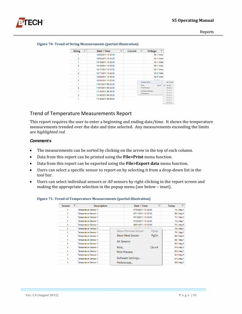
S5OperatingManual
Reports
Ver.2.0(August2012) P a g e |91
Figure70‐TrendofStringMeasurements(partialillustration)
Trend of Temperature Measurements Report
Thisreportrequirestheusertoenterabeginningandendingdate/time.Itshowsthetemperaturemeasurementstrendedoverthedateandtimeselected.Anymeasurementsexceedingthelimitsarehighlightedred.
Comments
Themeasurementscanbesortedbyclickingonthearrowinthetopofeachcolumn.
DatafromthisreportcanbeprintedusingtheFile>Printmenufunction.
DatafromthisreportcanbeexportedusingtheFile>Exportdatamenufunction.
Userscanselectaspecificsensortoreportonbyselectingitfromadrop‐downlistinthetoolbar.
UserscanselectindividualsensorsorAllsensorsbyright‐clickinginthereportscreenandmakingtheappropriateselectioninthepopupmenu(seebelow–inset).
Figure71‐TrendofTemperatureMeasurements(partialillustration)

S5OperatingManual
Reports
Ver.2.0(August2012) P a g e |92
Discharge Durations Report
Thisreportrequirestheusertoenterabeginningandendingdate/time.Itdisplaysthedate/timethedischargetookplaceandthelengthoftimeitlasted.
Comments
Themeasurementscanbesortedbyclickingonthearrowinthetopofeachcolumn.
DatafromthisreportcanbeprintedusingtheFile>Printmenufunction.
DatafromthisreportcanbeexportedusingtheFile>Exportdatamenufunction.
Figure72‐DischargeDurationsReport
Cumulative Durations Report
Thisreportrequirestheusertoenterabeginningandendingdate/time.Itshowsthecumulativenumberanddurationofdischargesovertheselecteddateandtimerange.Italsoshowsthedistributionofdischargesbyduration.Foreachdurationcategory,itliststhenumberofdischarges,itspercentageofthetotalnumberofdischarges,thecumulativedischargetime,andthepercentageofthetotaldischargetime.
ThedurationcategoriescanbechangedintheChangeDischargeDurationGroupingscreenaccessedfromtheViewmenu(seeFigure37,pg.54).
Comments
DatafromthisreportcanbeprintedusingtheFile>Printmenufunction.
DatafromthisreportcanbeexportedusingtheFile>Exportdatamenufunction.
ThegroupingfortheDischargeDatacanbere‐groupedbyright‐clickinginthereportscreenandselectingChangeDischargeDurationGroup,seebelow–inset).

S5OperatingManual
Reports
Ver.2.0(August2012) P a g e |93
Figure73‐CumulativeDurationsReport(partialillustration)
Discharge Duration Grouping Screen
Thisscreenisusedtoviewormodifythe15categoriesgroupings.
Figure74‐DischargeDurationGroupingscreen
System Discharge Measurements Report
Thisreportrequirestheusertoenterabeginningandendingdate/time.Itshowsthesystem'svoltage,dischargecurrent,averageunittemp,andambienttempwhilethebatteryisundergoingdischarge.Anymeasurementsexceedingthedischargelimitsareshowninred.Themeasurements(voltage,current,ortemperature)causingtheoutoflimitsconditionaredisplayedinbold.Anycurrentmeasurementsexceedingthesystemchargecurrentlimitorvoltagemeasurementsoutsidethevoltagelimitsarehighlightedinred.
Comments
TheDate/Timeentriescanbesortedbyclickingonthearrowinthetopofeachcolumn.
DatafromthisreportcanbeprintedusingtheFile>Printmenufunction.
DatafromthisreportcanbeexportedusingtheFile>Exportdatamenufunction.
Ifthesystemvoltageandcurrentarebothavailable,thedischargeperformanceiscalculatedandshownatthebottomofthereport.

S5OperatingManual
Reports
Ver.2.0(August2012) P a g e |94
Figure75‐SystemDischargeMeasurementsReport(partialillustration)
String Discharge Measurements Report
Thisreportrequirestheusertoenterabeginningandendingdate/time.Itshowsdischargecurrentwhilethebatteryisinadischargeforoneormorestrings.Withthelatestfirmware,thereportsalsoshowtheindividualstringvoltages.Anymeasurementsexceedingthestringdischargecurrentlimit,orthevoltagelimits,arehighlightedinred.
Comments
Themeasurementscanbesortedbyclickingonthearrowinthetopofeachcolumn.
DatafromthisreportcanbeprintedusingtheFile>Printmenufunction.
DatafromthisreportcanbeexportedusingtheFile>Exportdatamenufunction.
Theusercanselectaspecificstringforthereportbyselectingitfromadrop‐downlistinthetoolbar;orbyright‐clickinginthereportscreenandselectingitfromthetheDisplayStringsub‐menu,seebelow–inset).
Ifonestringisselectedandthestringvoltageandcurrentarebothavailable,thedischargeperformanceiscalculatedandshownatthebottomofthereport.

S5OperatingManual
Reports
Ver.2.0(August2012) P a g e |95
Figure76‐StringDischargeMeasurementsReport(partialillustration)
Temperature Discharge Measurements Report
Thisreportrequirestheusertoenterabeginningandendingdate/time.Itshowsthetemperaturemeasurementsoverthedateandtimeselected.Anymeasurementsexceedingthelimitsarehighlighted.
Comments
Themeasurementscanbesortedbyclickingonthearrowinthetopofeachcolumn.
DatafromthisreportcanbeprintedusingtheFile>Printmenufunction.
DatafromthisreportcanbeexportedusingtheFile>Exportdatamenufunction.
Theusercanselectaspecificstringtoreportonbyselectingitfromadrop‐downlistinthetoolbar.
Figure77‐TemperatureDischargeMeasurementsReport(partialillustration)
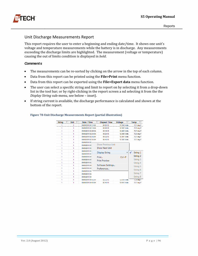
S5OperatingManual
Reports
Ver.2.0(August2012) P a g e |96
Unit Discharge Measurements Report
Thisreportrequirestheusertoenterabeginningandendingdate/time.Itshowsoneunit'svoltageandtemperaturemeasurementswhilethebatteryisindischarge.Anymeasurementsexceedingthedischargelimitsarehighlighted.Themeasurement(voltageortemperature)causingtheoutoflimitsconditionisdisplayedinbold.
Comments
Themeasurementscanbere‐sortedbyclickingonthearrowinthetopofeachcolumn.
DatafromthisreportcanbeprintedusingtheFile>Printmenufunction.
DatafromthisreportcanbeexportedusingtheFile>Exportdatamenufunction.
Theusercanselectaspecificstringandlimittoreportonbyselectingitfromadrop‐downlistinthetoolbar;orbyright‐clickinginthereportscreenandselectingitfromthetheDisplayStringsub‐menu,seebelow–inset).
Ifstringcurrentisavailable,thedischargeperformanceiscalculatedandshownatthebottomofthereport.
Figure78‐UnitDischargeMeasurementsReport(partialillustration)

S5OperatingManual
Appendix
Ver.2.0(August2012) P a g e |97
8. Graphs TheBVM4graphingoptionsareaccessedfromthemenubarand,insomecasestheHomescreensidebar(see,page16).SomeS5datacanbegraphedonuptofourparameters(Voltage,Current,Impedance,andTemperature).GraphscanbeprintedeitherbyselectingPrintfromtheFilemenuorclickingthePrinticonintheIconbar.
ThegraphingfeatureusestherangeandotherparametersenteredwhenconfiguringtheBVM4software.Symbolsandcolorscanbechosenorchangedusingthecustomizationfeature.
Figure79‐Selectinggraph
If an icon is grayed out (unavailable) it cannot be used for the graph type selected from the menu or side bar.
General Information
Date-Time Parameters
Mostreportsrequiretheusertoenterone,orapairofdatesandtimes(seebelow).Generallythisisdoneinacalendarspinbox.Ifnodateisavailableitmeansnodataiscurrentlyavailableforthegraph.BVMwillgenerallydisplaydefaultdates/timeswhichcanbechanged.
Figure80‐Date‐TimeSpinbox.Someboxesonlyhaveoneentry
Viewing Individual Unit and String Measurements

S5OperatingManual
Appendix
Ver.2.0(August2012) P a g e |98
Manygraphsincludeafeatureallowingausertoviewindividualmeasurementsforspecificdatapoints.Placingthecursoronagraphedmeasuringpointwilldisplaya‘tooltip’showingtheactualmeasurementdata(seeFigure83,page101).Mostillustrationsinthissectionincludeexamplesofthisfeature.
Exporting Graphs
MostgraphscanbeexportedinoneormoregraphicalformatsbyselectingFileinthemenubarandclickingExportGraphic.Asubmenuofoptionsisdisplayedshowingtheavailableexportformatoptions.
Printing Graphs
Some–butnotall–graphscanbeprinteddirectlyfromtheFilemenuinthemenubar.IfthePrintoptionisunavailableinthemenulistthedatamustbeexportedtoanotherapplicationtobeprinted.
Graph Menu
TheBMV4GraphmenuincludestheoptionsshowninFigure67.Notethatnotallgraphsareavailableatalltimes.Afterselectingthegraphtitleandenteringdates,oneormoreoftheparametericons(current,impedance,temperature,orvoltage)maybeavailableintheiconbar.Selectingoneoftheseiconsdeterminespreciselywhichmeasurementwillbegraphed.
Whenaparticulargraphstylecanbeswitchedamongseveraldifferentparameters(oneatatime)pressingF10willcyclethroughtheavailableparameters.
Sources for Graphs
SomeGraphscanbegeneratedfrommultiplesources(typicallytheHomescreensidebarandtheGraphsmenu).Itmakesnodifferencewhichsourceisused.Ineithercasedate/timeparametersusuallymustbeentered.Inafewinstancesgraphscommontotwosourceshaveslightlydifferenttitlesineachsource.Whenthisoccursbothtitlesarereferencedinthespecificgraphdescriptionslaterinthissection.
Graphs available from multiple sources will only be described once this section.

S5OperatingManual
Appendix
Ver.2.0(August2012) P a g e |99
Figure81‐TheBVM4‘Graphs’drop‐downmenu
Setting Graph Display Parameters and Features
ManyoftheGraphingparameterssuchasdatesareselectedatthetimethegraphiscreated.Otherparameterssuchasrangesaresetwhenthesoftwareisconfigured.Allgraphstyleshavedefaultsettings.Somedisplayparametersforsomegraphs,suchasbarandlinecolors,markersymbols,etc.,canbechangedwhenthegraphisopenandselectedbyusingtheViewmenu,(seeFigure82,below).
Thesecommandsarealsoavailable(onanindividualgraphbasis)fromacontextmenuthatisdisplayedbyright‐clickingonthegraph.
Graphscanbesavedasanimagefile(bmp,jpg,gif,orpng)usingtheExportGraphicsfunctionfoundintheFilemenu.
Not all graphs can have their formats changed and not all display parameters can be changed for all graphs. When a graph is selected only the options that appear under the View menu or in the popup menu can be changed.
The Graphs View Menu
TheViewmenucanbeusedtocontrolthedisplayalargenumberofcolor,symbol,andmarkershapesusedinagraph.Thegraphillustrationusedinthissectionshowavarietyoftheseoptions.Theactualoptionsavailableinthemenudependontheselectedgraphtype.Boththeitemsandtheoptionsshowninthemenuwillvary.Notalloptionsareavailableforallgraphs.
The View menu can be ‘popped up’ as a context menu within a graph panel by right‐clicking.

S5OperatingManual
Appendix
Ver.2.0(August2012) P a g e |100
Figure82‐AnextendedexampleoftheViewmenu.
BVMHomeScreenSideBarGraphs
ThesidepaneloftheHomescreenprovidesalistofreportsandgraphsthatBVMcangenerate(see
Figure8,page16).SomesidebarreportsarealsoavailablefromtheReportsmenubar.
Unit Snapshot Graph
Thisgraph–calledtheSnapshotofUnitMeasurementsintheGraphsmenu–canbedisplayedforeitherunitvoltage,impedance,ortemperaturemeasurementstakenduringone‘read’onone’specifieddate.Itrequirestheusertoselectaspecificdatefromadrop‐downlist.Usersmustenter/selectadateforthegraph.
Theunitnumbersareshownonthex‐axiswhilethevoltage,impedance,andtemperaturevaluesareshownonthey‐axis.Positionthemousepointeroverthemeasurementpointtoviewtheunitnumberandexactmeasurementvalueinatooltip.Double‐clickingonthemeasurementofaparticularunitwillopenaUnitTrendGraphofthatunit.
Comments
ThisgraphcanbegeneratedforCurrent,Impedence.orTemperaturebyclickingtheappropriateiconintheiconbar,orbypressingF10.
IndividualGraphdatacanbeexportedorprintedusingtheFilemenu.
Placingthecursoronabarorsymbolwilldisplayindividualunitdatainatooltip.
Theusercanelecttographdataforallstrings,orselectaspecificstringfromadrop‐downlistinthedtoolbar.
Datacanbedisplayedaseitherbars(shown)ordatapointsbypressingF8.

S5OperatingManual
Appendix
Ver.2.0(August2012) P a g e |101
Figure83‐UnitSnapshot[ofUnitMeasurements]GraphsforVoltage,Impedance,andTemperature
Unit Trend Graph
Thisgraph–calledtheTrendofUnitMeasurementsintheGraphsmenu–showoneunit’sVoltage,Impedance,orTemperatureforauser‐specifiedrangeofdates.Thegraph'sx‐axiswillvarydependingontheperiodoftimeselected.
Theunitmaintenancevoltagelimitsarerepresentedbytwopurpledashedlines.Criticallimitsarerepresentedbytworedlines.Theunitfloatvoltageshouldremainsteadybetweenthosetwolimits.Abest‐fitcurveofthevoltageandimpedancemeasurementsisgraphedtoassisttheuserinspottingarisingorfallingunitvoltageorimpedance.Todisablethisfeature,un‐checktheDisplayBestFitVoltageMeasurementTrend.
Comments
ThisgraphcanbegeneratedforCurrent,Impedence.orTemperaturebyclickingtheappropriateiconintheiconbarorpressingF10.
Userscanselectaspecificstringandunitfromthedrop‐downlistinthetoolbar.
IndividualGraphdatacanbeexportedorprintedusingtheFilemenu.
Placingthecursoronabarorsymbolwilldisplayindividualunitdatainatooltip.
Datacanbegraphedaseitherdatapoints(shown)orbarsbypressingF8.

S5OperatingManual
Appendix
Ver.2.0(August2012) P a g e |102
Figure84‐UnitTrend(TrendofUnitMeasurement)GraphsforVoltage,Impedance,andTemperature
Temp Trend
Called“TrendofTemperatureMeasurements”intheGraphsmenu,itshowsthetemperaturemeasurementstrendedoverthedatesandtimesselected.
Toincreaseordecreasethedateandtimerangeofthedisplayedmeasurements,usetheZoomInorZoomOutselectionintheViewmenu.
Figure85‐TemperatureTrends(TrendofTemperatureMeasurements)Graph
Comments
IndividualGraphdatacanbeexportedorprintedusingtheFilemenu.
Placingthecursoronabarorsymbolwilldisplayindividualunitdatainatooltip.
Userscanselectaspecificsensorfromthedrop‐downlistinthetoolbar.
Datacanbegraphedaseitherdatapoints(shown)orbarsbypressingF8.

S5OperatingManual
Appendix
Ver.2.0(August2012) P a g e |103
String Trend
Calledthe“TrendofStringMeasurementsGraph”intheGraphsmenu–itshowsstringchargecurrentsoveraperiodoftime.Withthelatestfirmware,thegraphswillalsoshowtheindividualstringvoltages.Thegraph'sx‐axisvariesdependingonthetimeperiodselected.
Figure86‐StringTrend(TrendofStringMeasurements)Graph
Comments
Anycurrentmeasurementsexceedingthestringchargecurrentlimitorvoltagemeasurementsoutsidethevoltagelimitsarehighlightedinred.
IndividualGraphdatacanbeexportedorprintedusingtheFilemenu.
Placingthecursoronabarorsymbolwilldisplayindividualunitdatainatooltip.
Datacanbegraphedaseitherdatapoints(shown)orbarsbypressingF8.
Theusercangraphdatafromaspecificstringbyselectingitfromadrop‐downlistinthetoolbar.
System Trend
Calledthe“TrendofSystemMeasurements”intheGraphsmenu–itshowsthesystem’sVoltage,ChargeCurrent,orAverageUnitTemperature,andAmbientTemperatureforauser‐specifiedrangeofdates.Thegraph'sx‐axisvariesdependingontheperiodoftimeselected.

S5OperatingManual
Appendix
Ver.2.0(August2012) P a g e |104
Figure87‐SystemTrend(TrendofSystemMeasurements)Graph

S5OperatingManual
Appendix
Ver.2.0(August2012) P a g e |105
DischargeGraphs–MenuBar
Power Outage Intervals Graph
Thisgraphshowsthedistributionofdischargesforhours‐of‐the‐day,days‐of‐the‐week,ormonths‐of‐the‐yearovertheuser‐determineddateandtimerange.Thedistributionofdischargesbythedurationoftheoutagescanalsobegraphed.Thedatacanbeclassifiedeitherbythenumberofdischargesorbythedischargedurations,
Comments
ThedurationcategoriescanbechangedintheChangeDischargeDurationGroupingscreenaccessedfromtheViewmenu.
Placingthecursoronabarorsymbolwilldisplayindividualunitdatainatooltip.
Thegraphcanbesavedasanimagefile(bmp,jpg,gif,orpng)usingtheExportGraphicsfunctionfoundintheFilemenu.
ThegraphcanbeprintedfromtheFilemenu.
Figure88‐PowerOutageIntervalGraph
Snapshot of Unit Discharge Measurements Graph
Thesegraphsdepictthevoltageandtemperaturemeasurementstakenduringonemeasurementscanforeitherasinglestringorallstringsinthebatterysystem.Thegraph'sx‐axisvariesdependingontheperiodoftimeselected.
Anymeasurementsexceedingthedischargelimitsarehighlighted.Ifaunitisreplaced,themeasurementstakenbeforethenew(replacement)unitisinstalledaredimmed.Todeterminethedateandexactmeasurementvaluerepresentedbyayellowdiamond,placethemousecursoroverthemeasurement.Thestringandunitnumberandvalueareshowninatooltip.
Comments
Toscrollthetimeofthedisplayedmeasurements,usetheleftandrightarrowkeys.
UseF10totogglebetweentheunitvoltageandunittemperature.
Totogglebetweendatapoints(shown),orbarspressF8.
BVMcangraphaverage,initial,max,min,andlimitsdata.EachdatatypecanbeenabledanddisabledintheViewmenu.

S5OperatingManual
Appendix
Ver.2.0(August2012) P a g e |106
Placingthecursoronabarorsymbolwilldisplayindividualunitdatainatooltip.
ThePageUpandPageDownkeyscanbeusedtochangethegraphtothepreviousornextunit'sdata.
Toincreaseordecreasethedateandtimerangeofthedisplayedmeasurements,usethe“ZoomIn”and“ZoomOut”selectionsintheViewmenu.
Theusercansellectallstringsorspecificstringsfromadrop‐downlistinthetoolbar.
Double‐clickingonthemeasurementofaparticularunitwillopenaUnitTrendGraphofthatunit.
Figure89‐VoltageandTemperatureDischargeMeasurementsGraph
System Discharge Voltage and Current Measurements Graphs
Thesegraphsshowthesystem'svoltage,current,averagetemp,andambienttempwhilethebatteryisinadischarge.Thegraph'sx‐axiswillvarydependingonthetimeperiodselected.Thestringdischargecurrentlimitisshownasapurpledashedline.Thecurrentshouldremainbelowthelineduringthedischargeoperation.Onthestringvoltagegraph,thedischargevoltagelimitsarerepresentedbytwodashedlines.Thestringvoltageshouldnotgobelowtheselimitsduringadischarge.
Comments
UsetheF10keytotogglebetweengraphsforVoltageandTemperature.
Toscrollthedateandtimeofthedisplayedmeasurementsusetheleftandrightarrowkeys.
Placingthecursoronabarorsymbolwilldisplayindividualunitdatainatooltip.
Thegraphcanbesavedasanimagefile(bmp,jpg,gif,orpng)usingtheExportGraphicsfunctionfoundintheFilemenu.
ThegraphcanbeprintedfromtheFilemenu.

S5OperatingManual
Appendix
Ver.2.0(August2012) P a g e |107
Figure90‐SystemDischargeVoltageandCurrentTrendGraphs
String Discharge Measurements Graph
Thisgraphshowsstringdischargecurrenttakenfromthebatteryduringdischarge.Withthelatestfirmware,thegraphswillalsoshowtheindividualstringvoltages.Thegraph'sx‐axiswillvarydependingontheperiodoftimeselected.
Thestringdischargecurrentlimitisshownasapurpledashedline.Thecurrentshouldremainbelowthislineduringthedischargeoperation.Onthestringvoltagegraph,thedischargevoltagelimitsarerepresentedbytwodashedlines.Thestringvoltageshouldremainbetweentheselimitsduringadischargeoranalarmwillbegenerated.
Comments
Thegraphcanbesavedasanimagefile(bmp,jpg,gif,orpng)usingtheExportGraphicsfunctionfoundintheFilemenu.
ThegraphcanbeprintedfromtheFilemenu.
Placingthecursoronabarorsymbolwilldisplayindividualunitdatainatooltip.
Theusercangraphdataforindividualstringsbyselectingastringfromadrop‐downlistinthetoolbar.

S5OperatingManual
Appendix
Ver.2.0(August2012) P a g e |108
Figure91‐StringDischargeMeasurementGraph(partialillustration)
Toscrollthedateandtimeofthedisplayedmeasurements,usetheleftandrightarrowkeys.Todeterminethedateandexactmeasurementvaluerepresentedbyareddiamond,placethemousecursoroverthemeasurement.Themeasurementanditsvalueareshowninapop‐upwindow.Toincreaseordecreasethedateandtimerangeofthedisplayedmeasurements,usetheZoomInorZoomOutselectionintheViewmenu.
Temperature Discharge Measurements Graph
Thisgraphshowsthetemperaturesensormeasurementstakenwhilethebatteryisunderdischarge.Thegraph'sx‐axiswillvarydependingontheperiodoftimeselected.Thereddashedlineonthetemperaturegraphshowsthetemperaturelimits.Boththeambientandtemperaturemeasurementshouldremainwithinthelimits.
Comments
Thegraphcanbesavedasanimagefile(bmp,jpg,gif,orpng)usingtheExportGraphicsfunctionfoundintheFilemenu.
Placingthecursoronabarorsymbolwilldisplayindividualunitdatainatooltip.
ThegraphcanbeprintedfromtheFilemenu.
Thedatacanbegraphedasbarsordatapoints(shown).
Theusercanselectindividualsensorsfromadrop‐downlistinthetoolbar.

S5OperatingManual
Appendix
Ver.2.0(August2012) P a g e |109
Figure92‐TemperatureDischargeMeasurementGraph
Unit Discharge Measurements Graphs
Thesegraphsshowoneunit’svoltageortemperaturemeasurementstakenwhilethebatteryisunderdischarge.Thegraph'sx‐axiswillvarydependingontheperiodoftimeselected.
Todeterminethedateandexactmeasurementvaluerepresentedbyayellowdiamond,placethemousecursoroverthemeasurement.Thestringandunitnumberandvaluewillbeshownintooltip.Toincreaseordecreasethedateandtimerangeofthedisplayedmeasurements,usetheZoomInorZoomOutselectionintheViewmenu.
OntheunitVoltagegraph,theunitdischargevoltagelimitsarerepresentedbytwocoloreddashedlines.Theunitvoltageshouldnotgobelowthesevoltagesduringadischarge.UnitTemperaturesduringdischargearealsoavailableonthegraph.Duringadischarge,unittemperatureswillelevatewithinareasonablerange.
Comments
Thegraphcanbesavedasanimagefile(bmp,jpg,gif,orpng)usingtheExportGraphicsfunctionfoundintheFilemenu.
ThegraphcanbeprintedfromtheFilemenu.
Ifaunitisreplaced,themeasurementstakenbeforethereplacementunitisinstalledaredimmed.
Theusercantogglebetweenbarsanddatapoints(shown)bypressingF8.
Placingthecursoronabarorsymbolwilldisplayindividualunitdatainatooltip.
UseF10totogglebetweentheunitVoltageandunitTemperature.
Theusercanselectastringandunitfromadrop‐downlistinthetoolbar.

S5OperatingManual
Appendix
Ver.2.0(August2012) P a g e |110
Figure93‐UnitDischargeMeasurementsGraph

Appendix
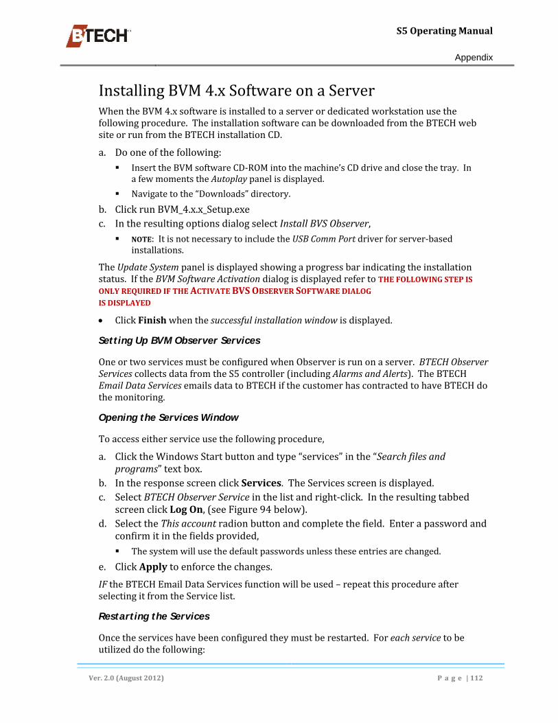
S5OperatingManual
Appendix
Ver.2.0(August2012) P a g e |112
InstallingBVM4.xSoftwareonaServerWhentheBVM4.xsoftwareisinstalledtoaserverordedicatedworkstationusethefollowingprocedure.TheinstallationsoftwarecanbedownloadedfromtheBTECHwebsiteorrunfromtheBTECHinstallationCD.
a. Dooneofthefollowing: InserttheBVMsoftwareCD‐ROMintothemachine’sCDdriveandclosethetray.In
afewmomentstheAutoplaypanelisdisplayed.
Navigatetothe“Downloads”directory.
b. ClickrunBVM_4.x.x_Setup.exec. IntheresultingoptionsdialogselectInstallBVSObserver, NOTE:ItisnotnecessarytoincludetheUSBCommPortdriverforserver‐based
installations.
TheUpdateSystempanelisdisplayedshowingaprogressbarindicatingtheinstallationstatus.IftheBVMSoftwareActivationdialogisdisplayedrefertoTHEFOLLOWINGSTEPISONLYREQUIREDIFTHEACTIVATEBVSOBSERVERSOFTWAREDIALOGISDISPLAYED
ClickFinishwhenthesuccessfulinstallationwindowisdisplayed.
Setting Up BVM Observer Services
OneortwoservicesmustbeconfiguredwhenObserverisrunonaserver.BTECHObserverServicescollectsdatafromtheS5controller(includingAlarmsandAlerts).TheBTECHEmailDataServicesemailsdatatoBTECHifthecustomerhascontractedtohaveBTECHdothemonitoring.
Opening the Services Window
Toaccesseitherserviceusethefollowingprocedure,
a. ClicktheWindowsStartbuttonandtype“services”inthe“Searchfilesandprograms”textbox.
b. IntheresponsescreenclickServices.TheServicesscreenisdisplayed.c. SelectBTECHObserverServiceinthelistandright‐click.Intheresultingtabbed
screenclickLogOn,(seeFigure94below).d. SelecttheThisaccountradionbuttonandcompletethefield.Enterapasswordand
confirmitinthefieldsprovided, Thesystemwillusethedefaultpasswordsunlesstheseentriesarechanged.
e. ClickApplytoenforcethechanges.
IFtheBTECHEmailDataServicesfunctionwillbeused–repeatthisprocedureafterselectingitfromtheServicelist.
Restarting the Services
Oncetheserviceshavebeenconfiguredtheymustberestarted.Foreachservicetobeutilizeddothefollowing:

S5OperatingManual
Appendix
Ver.2.0(August2012) P a g e |113
a. Selecteachoftheservice(s)toberestartedandrightclick.b. InthepopupmenuclickRestart.
Figure94‐ConfiguringBTECHObserverService

S5OperatingManual
Appendix
Ver.2.0(August2012) P a g e |114
Installing and Configuring SQL Server Software
Forlargersites(approximately20ormoreBTECHBVSS5units)BTECHrecommendsusingMicrosoftSQLServerExpress(inplaceofMicrosoftAccess)asthebackenddatabase.ServerExpressisusuallyincludedontheBTECHinstallationCD.InsituationswherealocationhasincreasedthenumberofS5unitsovertime,ServerExpresscaninstalledtoreplaceAccess,see“ConvertingtoSQLfromMSAccess”,pg.126.IfafullversionofSQLisavailableitcanalsobeused.
SQL Server Express 2008 can be installed as the database engine regardless of the battery system size. It may be advisable to include it in the initial installation to avoid having to complete the conversion process at a later time.
Password Authentication
TheBVMsoftwarecanuseeitherSQLorWindowsauthenticationtoconnecttothedatabaseserver.Thetypeofauthentication,username,andpasswordwillbepartoftheconfigurationforeachofthesoftwarecomponents.Bydefault,therearetwoSQLlogins;oneisforwebaccessandtheotherisforBVMaccess.Eachusesthesamedefaultpassword:“p@ssw0rd”.
BTECH strongly recommends changing the password to more secure versions and then changing them periodically.
Installing SQL Server Express 2008
TheSQLServerExpress2008andtheSQLServerManagementTools,togetherwiththeinstallationapplication,areincludedontheBVMinstallationdisk.Both32‐bitand64‐bitversionsofSQLExpressareavailable.Becertaintoinstallthecorrectversionforthehostoperatingsystem.
Oncetheinstallationiscomplete,theTCP/IPprotocolneedstobeenabledifthebatterydatawillbeaccessedbyaremotemachinerunningBVMorBVSStatusMonitorsoftware.ToenableTCP/IP,launchtheSQLServerConfigurationManager.UndertheSQLServerNetworkConfiguration,enableTCP/IPandthenrestarttheSQLServerserviceunderSQLServerServices.
This guide section depicts a full install to a machine that does not have an existing SQL Express version resident and active.
ToinstallSQLExpress2008fromtheBTECHinstallationdiscdothefollowing:
a. UseWindowsExplorertonavigateto,anddownloadtheexecutableinstallfilefromtheBTECHinstallationCD– SQLEXPRWT_x86_ENU.exe.(32‐bit),or

S5OperatingManual
Appendix
Ver.2.0(August2012) P a g e |115
SQLEXPRWT_x64.exe(64‐bit),
Bydefault,WindowsdownloadsallfilestotheDownloadfolder.Thiscanbechangedinthedownloaddialogifnecessary.
b. Double‐clickonthecorrectinstallationfile.Anumberoffilesareextractedandanumberofprogressbardialogsaredisplayedinsuccession.
Be certain to download and install the correct file – 32‐bit or 64‐bit, for the host system OS. If the wrong program version is installed, delete it completely using the Widows Control panel and repeat this procedure for the correct program.
c. IntheSQLServerExpressInstallationCenterscreen,selectthe“NewInstallationoraddfeatures..“option(seeFigure95below),
d. Afterverifyingthattheinstallationcomputerhasthenecessaryhardware–acceptthelicensetermsandconditionsbyclickingNext.TheSetupSupportFilesscreenisdisplayedwithaprogressbaratthebottom. TheinstallprocessnextdisplaystheSetUpRulesscreenwithaprogressbaratthe
bottom.
e. TheSet‐upprogramcontinuestheinstalldisplayinganumberofinformationaldialogsandprogressbarpanels.
Figure95‐TheinitialSQLinstallationscreen
Installing SQL Express 2008 Features
TheFeatureSelectiondialogisdisplayedautomatically.Itisnotnecessary(oradvisable)toinstallalloftheavailablefeatures.IntheFeatureSelectionscreendothefollowing:
a. ClearthecheckboxforSQLServerReplication(ifitischecked),b. Leavethefollowingitemsselected(orselectthemifnecessary): DatabaseSelectionServices,
Managementtools–basic,
SQLClientConnectivitySDK.
c. ClickNext.

S5OperatingManual
Appendix
Ver.2.0(August2012) P a g e |116
Figure96‐TheSQLExpressServerFeatureSelectionscreen
Naming the Instance
Oncethebaseinstallationiscompletethefollowingitemsmustbeadded,(seeFigure97,below).
a. SelecttheNamedInstanceradiobutton(ifnecessary),b. Acceptthedefaultorchangethefollowing: Namedinstanceentry,
Instanceidentry,
Instancerootdirectoryentry.
c. ClickNexttoproceedtotheconfigurationportionoftheinstallation.
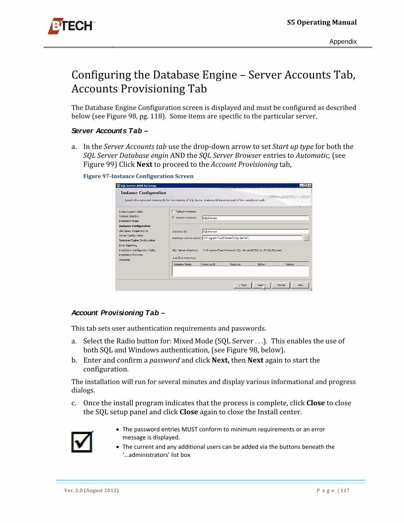
S5OperatingManual
Appendix
Ver.2.0(August2012) P a g e |117
ConfiguringtheDatabaseEngine–ServerAccountsTab,AccountsProvisioningTab
TheDatabaseEngineConfigurationscreenisdisplayedandmustbeconfiguredasdescribedbelow(seeFigure98,pg.118).Someitemsarespecifictotheparticularserver.
Server Accounts Tab –
a. IntheServerAccountstabusethedrop‐downarrowtosetStartuptypeforboththeSQLServerDatabaseenginANDtheSQLServerBrowserentriestoAutomatic,(seeFigure99)ClickNexttoproceedtotheAccountProvisioningtab,
Figure97‐InstanceConfigurationScreen
Account Provisioning Tab –
Thistabsetsuserauthenticationrequirementsandpasswords.
a. SelecttheRadiobuttonfor:MixedMode(SQLServer...).ThisenablestheuseofbothSQLandWindowsauthentication,(seeFigure98,below).
b. EnterandconfirmapasswordandclickNext,thenNextagaintostarttheconfiguration.
Theinstallationwillrunforseveralminutesanddisplayvariousinformationalandprogressdialogs.
c. Oncetheinstallprogramindicatesthattheprocessiscomplete,clickClosetoclosetheSQLsetuppanelandclickCloseagaintoclosetheInstallcenter.
The password entries MUST conform to minimum requirements or an error message is displayed.
The current and any additional users can be added via the buttons beneath the ‘…administrators’ list box

S5OperatingManual
Appendix
Ver.2.0(August2012) P a g e |118
Figure98‐AccountProvisioningtab
Figure99‐ServiceAccountstab
ConfiguringandControllingSQLNetworkAccess
BydefaultSQLExpressdoesnothavenetworkaccess.Itmustbeturnedonusingthemanagementtools.Intheprogramslist,navigateto:
MicrosoftSQLServer2008R2>SQLServerManagementStudio>ConfigurationTools>SQLServerConfigurationManager.
Configuring Network Access to Server Express
a. ClicktheWidowsStartbutton,andselectAllPrograms,b. ClickMicrosoftSQLServer2008toexpanditandselectandexpandConfiguration
toolsintheresultinglist,c. SelectSQLServerConfigurationManagertodisplaythepropertiespanels,

S5OperatingManual
Appendix
Ver.2.0(August2012) P a g e |119
d. IntheleftpanelselectandexpandSQLservernewtworkconfiguration,e. SelectProtocolsforSQLExpressintheexpandedlistand–f. intherightpanel,right‐clickonTCP/IP,g. selectEnablefromthepop‐upmenuandclickOKintheWarningdialog.h. ReturntotheleftpanelandselectSQLServerServicesi. Right‐clickSQLServer(SQLExpress)intherightpanelandselectStopinthepopup
menu.j. SelectSQLServerBrowserintherightpanel.andselectStopinthepopupmenu.k. RepeattheprocessinstepsandhbutselectStartinthepopupmenu.
Figure100‐InstalleddirectorystructureforSQLserver
Stopping and Starting SQL Services
Inordertoactivatetheconfigurationsettingsthathavebeenaddedorchanged,it’snecessarytostop,andre‐starttwoSQLservices.ThisisdonefromtheSQLServerConfigurationManager(seeFigure101)asfollows.
a. IntheleftsidenavigationpanelselectSQLServerServices,b. Intherightpanel–rightclickSQLServerandselectStopfromthepopupmenu,c. SelectSQLServerBrowser–rightclick,andselectStopfromthepopupmenu,d. RepeatstepsbandcbutselectStartfromthepopupmenu.
Whentheprocedurestepsarefinished,thetwoservicesshouldshow“Running”intheStatecolumn.ClosetheInstallationscreen.
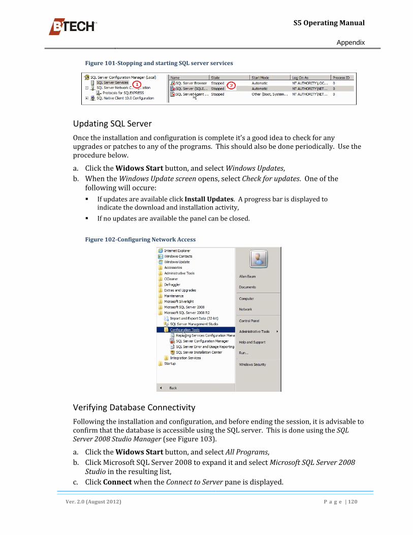
S5OperatingManual
Appendix
Ver.2.0(August2012) P a g e |120
Figure101‐StoppingandstartingSQLserverservices
Updating SQL Server
Oncetheinstallationandconfigurationiscompleteit’sagoodideatocheckforanyupgradesorpatchestoanyoftheprograms.Thisshouldalsobedoneperiodically.Usetheprocedurebelow.
a. ClicktheWidowsStartbutton,andselectWindowsUpdates,b. WhentheWindowsUpdatescreenopens,selectCheckforupdates.Oneofthe
followingwilloccure: IfupdatesareavailableclickInstallUpdates.Aprogressbarisdisplayedto
indicatethedownloadandinstallationactivity,
Ifnoupdatesareavailablethepanelcanbeclosed.
Figure102‐ConfiguringNetworkAccess
Verifying Database Connectivity
Followingtheinstallationandconfiguration,andbeforeendingthesession,itisadvisabletoconfirmthatthedatabaseisaccessibleusingtheSQLserver.ThisisdoneusingtheSQLServer2008StudioManager(seeFigure103).
a. ClicktheWidowsStartbutton,andselectAllPrograms,b. ClickMicrosoftSQLServer2008toexpanditandselectMicrosoftSQLServer2008
Studiointheresultinglist,c. ClickConnectwhentheConnecttoServerpaneisdisplayed.

S5OperatingManual
Appendix
Ver.2.0(August2012) P a g e |121
Ifanyerrorsoccuraddressthematthispoint.Otherwiseapanelisdisplayedshowingthedatabasestructureusingexpandableelements.Administratorscanselectelementsforviewingandediting.
Figure103‐TheSQLExpressServerdatabaseConnecttoServerpanel
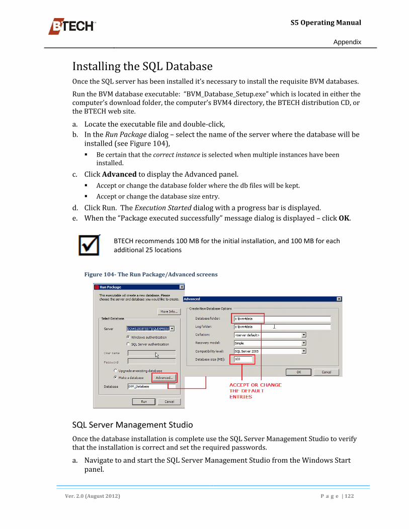
S5OperatingManual
Appendix
Ver.2.0(August2012) P a g e |122
InstallingtheSQLDatabaseOncetheSQLserverhasbeeninstalledit’snecessarytoinstalltherequisiteBVMdatabases.
RuntheBVMdatabaseexecutable:“BVM_Database_Setup.exe”whichislocatedineitherthecomputer’sdownloadfolder,thecomputer’sBVM4directory,theBTECHdistributionCD,ortheBTECHwebsite.
a. Locatetheexecutablefileanddouble‐click,b. IntheRunPackagedialog–selectthenameoftheserverwherethedatabasewillbe
installed(seeFigure104), Becertainthatthecorrectinstanceisselectedwhenmultipleinstanceshavebeen
installed.
c. ClickAdvancedtodisplaytheAdvancedpanel. Acceptorchangethedatabasefolderwherethedbfileswillbekept.
Acceptorchangethedatabasesizeentry.
d. ClickRun.TheExecutionStarteddialogwithaprogressbarisdisplayed.e. Whenthe“Packageexecutedsuccessfully”messagedialogisdisplayed–clickOK.
BTECH recommends 100 MB for the initial installation, and 100 MB for each additional 25 locations
Figure104‐TheRunPackage/Advancedscreens
SQL Server Management Studio
OncethedatabaseinstallationiscompleteusetheSQLServerManagementStudiotoverifythattheinstallationiscorrectandsettherequiredpasswords.
a. NavigatetoandstarttheSQLServerManagementStudiofromtheWindowsStartpanel.

S5OperatingManual
Appendix
Ver.2.0(August2012) P a g e |123
ClickConnectintheConnecttoServerdialog,(seebelow).Thisdisplaysatwp‐panelscreen.
Figure105‐TheConnecttoServerdialog
Setting User Passwords
a. ClickSecuritytoexpandit,andselectLoginsintheleftpanel.ThelistexpandsasshowninFigure106.
b. Right‐clickoneitherbvm_userorbvmweb_usertodisplayapop‐upmenu.c. ClickPropertiestodisplaythePropertiespanelfortheselectedusertype.
Figure106‐SettingDatabaseServeruserpasswords
Setting User Properties and Passwords
a. InthePropertiesPanel(seeFigure107)changethepaswordfromthedefaulttoamoresecureoneandconfirmthechangeinthesecondfield.
b. Repeatsteps‘c’through‘e’forthebvmweb_userpassword.

S5OperatingManual
Appendix
Ver.2.0(August2012) P a g e |124
Figure107‐ChangingUserPasswords
ClosetheSQLServerManagementStudiotooloncethepasswordshavebeenchanged.
The default bvm_user password is P@ss0rd. The default bvmweb_user default password is the same as the default SQL Server login.
Configuring BVM to Work with the SQL Server
OncetheSQLserverisinstalledandconfiguredBVMmustbelinkedtoitandhavecertainitems(e.g.userpasswords)configured.TheconfigurationentriesrequiredforBVMandBVSObserveraredescribedinthissection.
a. StartBVMandclosethelocationlistpanelifit’sdisplayed.b. ClickSettingsinthemenubarandselectPreferencesfromthesubmenu.The
SoftwarePreferencesdialogisdisplayed.
c. Clickthe buttontodisplayalistwindow.Dropdownthelistandselectthecorrectserverinstance(seeFigure109).
d. Checkthe“UseSQLServerAuthentication”boxandenterorchangetheuserroleandpassword.
e. CloseBVM.

S5OperatingManual
Appendix
Ver.2.0(August2012) P a g e |125
Figure108‐SettingSQLServerAuthentication
SettingPasswordsinBVSObserver
a. OpenBVMObserverandselectLocations.b. ClickFileinthemenubarandselectObserverSettings.TheObserverSettingsdialog
isdisplayed(seeFigure109).c. EnterthesameuserroleandpasswordthatwasenteredintheBVMSettingsdialog.d. Repeatthisprocessforalladditionaluserroles.
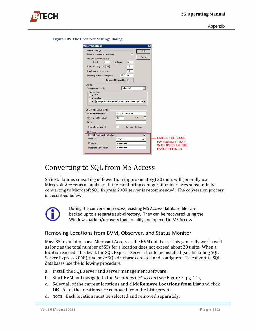
S5OperatingManual
Appendix
Ver.2.0(August2012) P a g e |126
Figure109‐TheObserverSettingsDialog
ConvertingtoSQLfromMSAccess
S5installationsconsistingoffewerthan(approximately)20unitswillgenerallyuseMicrosoftAccessasadatabase.IfthemonitoringconfigurationincreasessubstantiallyconvertingtoMicrosoftSQLExpress2008serverisrecommended.Theconversionprocessisdescribedbelow.
During the conversion process, existing MS Access database files are backed up to a separate sub‐directory. They can be recovered using the Windows backup/recovery functionality and opened in MS Access.
Removing Locations from BVM, Observer, and Status Monitor
MostS5installationsuseMicrosoftAccessastheBVMdatabase.ThisgenerallyworkswellaslongasthetotalnumberofS5sforalocationdoesnotexceedabout20units.Whenalocationexceedsthislevel,theSQLExpressServershouldbeinstalled(seeInstallingSQLServerExpress2008),andhaveSQLdatabasescreatedandconfigured.ToconverttoSQLdatabasesusethefollowingprocedure.
a. InstalltheSQLserverandservermanagementsoftware.b. StartBVMandnavigatetotheLocationsListscreen(seeFigure5,pg.11),c. SelectallofthecurrentlocationsandclickRemoveLocationsfromListandclick
OK.AllofthelocationsareremovedfromtheListscreen.d. NOTE:Eachlocationmustbeselectedandremovedseparately.

S5OperatingManual
Appendix
Ver.2.0(August2012) P a g e |127
e. StartObserver
OncethelocationshavebeenremovedconfigureBVMtoworkwithSQL,(seeConfiguringBVMtoWorkwiththeSQLServer,above).
Adding Locations to SQL
AfterBVMhasbeenconfiguredtoworkwithSQLaddthelocationsasfollows:
a. IntheLocationsListscreenclickAddLocation(s)toList.WindowsExploreropensanddisplaysthe.bvmfilesonthecomputer’sBVM4directory. NOTE:referto
StartingBVMandTransferringLocationFilesfromtheCD,pg.10.
b. Selectalloftheappropriate.bvmfilesfromtheCDandclickOK.c. IntheoptiondialogselectSQL.
AlloftheLocationfileswillnowhavetheirdatakeptinanSQLdatabase.
Using BVS Observer and Status Monitor in an SQL Environment
TheBVMObserverandtheStatusMonitor(ifinstalled)iscompatiblewithanSQLdatabaseoncethefollowingstepsareperformed.Notethatthestepsmustbeperformedseparatelyforeachapplication.
Convert the BVM 4.x software to SQL as described above prior to converting Observer
a. StarttheBVSObserverorStatusMonitor.IftheBVMHomescreenisdisplayedcloseit,(see,pg.16).
b. IntheblankBVMscreenopentheLocationListscreenbyselectingFile‐OpeninthemenubarorclickingtheFileiconintheiconbar,(seeFigure5,pg.11).
c. SelecteachofthecurrentlocationsandclickRemoveLocationsfromList.ClickOK.AllofthelocationsareremovedfromtheListscreen. NOTE:Eachlocationmustbeselectedandremovedindividually.
d. Closeandre‐openBVSObserverandnavigatetotheLocationListscreen(ifnecessary).
e. ClickAddLocationstoList(s).f. WindowsExploreropensanddisplaysthe.bvmfilesonthecomputer’sharddrive.g. Selectalloftheappropriate.bvmfilesandclickOK.
ThesefilesareaddedtotheBVSObserverthatisnowutilizingSQL.

S5OperatingManual
Appendix
Ver.2.0(August2012) P a g e |128
BVMHomeScreenDisplayOptionsTheBVMhomescreentypicallyusesadefaultsetofstylestodisplaystringdata.Someofthestylescanbechangedasdescribedbelow.AnystylechangesmadebyauserbecomethedefaultandtheHomescreenforallstringswillusethem.
TherearealimitednumberofoptionsthatausercanselectthatcontrolthewaytheStringandUnitarchitectureisdisplayed.Onceadesireddisplayisachieveditcanbelockedsothatotheruserscannotchangeit.Settingdisplayoptionsisdoneeitherby:
a. ClickingViewintheMenubarandselectiongtheconfigurationoptionsfromtheresultingmenulistor,
b. Right‐clickingintheHomescreenandselectingtheconfigurationoptionsfromthepopupmenu(shownbelow).
Figure110‐TheHomeScreenPopupConfigurationMenu
Table22. HomeScreenConfigurationOptions
Reverse String Order – This option displays the stings from highest to lowest numbered, i.e. negative to positive (reverses the default order)
Set String Label – Enables the user to set custom labels for each string
Change Unit Layout – Enables the user to display the individual unit blocks horizontally or ‘stacked’ in
columns. See Figure112 below. Unit Shape – Enables the user to select one of three shapes to display the individual units
Layout Locked – Enables the administrator to lock the display parameters so users cannot change them.
Thefollowingillustrationshowstheunitlistreversedandtheunitnumbersinhorizontalrectangles.Note–somechangeshavebeenmadetothegraphicbelowtoimprovereadability.

S5OperatingManual
Appendix
Ver.2.0(August2012) P a g e |129
Figure111–ExampleofHomescreenwithunitsinreverseorder
TheUnitlayoutbelowwaschangedtoa‘stacked’formatusingtheChangeUnitLayoutoption.
Figure112‐Achangedlayoutafterusing“ChangeUnitLayout
When‘ChangeUnitLayout’isselectedfromthemenuthefollowingdialogisdisplayed.ThisistheonlychangesthatcanbemadetotheUnitsdisplay.
Figure113‐TheChangeUnitLayoutdialog

S5OperatingManual
Appendix
Ver.2.0(August2012) P a g e |130
BatteryMonitorAlarms–Descriptions
AlarmMessageDescription
Error Message Cause
AC Power Failure – The battery monitor has detected a loss of AC power to itself.
Battery Discharge Alarm – The battery monitor has detected a discharge of the battery system.
System Voltage Alarm:450.0 Volts – The system or charger voltage is out of limits.
Critical Alarm: String 1 Unit 1 Voltage:12.500 Volts –
A unit voltage is outside of critical voltage limits.
Maint Alert: String 1 Unit 1 Voltage:12.750 Volts –
A unit voltage is outside of maintenance voltage limit.
Critical Alarm: String 1 Unit 1 Impedance:4.500 mOhms Average Method –
A unit impedance is above of the average critical impedance limit.
Maint Alert: String 1 Unit 1 Impedance:4.250 mOhms Average Method –
A unit impedance is above of the average maintenance impedance limit.
Critical Alarm: String 1 Unit 1 Impedance:4.500 mOhms Initial Method –
A unit impedance is above of the initial critical impedance limit.
Maint Alert: String 1 Unit 1 Impedance:4.250 mOhms Initial Method –
A unit impedance is above the initial maintenance impedance limit.
Ambient Temperature:95.0 deg F – The ambient temperature sensor is outside the temperature limits.
Battery Temperature 1:96.8 deg F – S3/S4 Alarm – A battery temperature sensor is outside the temperature limits.
String 1 Unit 1 Temperature:96.8 deg F – A unit temperature is outside of the temperature limits.
Battery Temperature 1 Alarm:18.0 deg F above ambient –
A battery temperature sensor is above the differential temperature limit. This indicates a possible thermal runaway.
String 1 Unit 1 Temperature Alarm:18.0 deg F above ambient –
A unit temperature is above the differential temperature limit. This indicates a possible thermal runaway.
Standby battery out of limits – The backup battery in the battery monitor is outside of limits. The battery may not be able to power the battery monitor when power is lost.
BVS is unlearned – The battery monitor doesn’t know the battery configuration.
BVS is unable to learn – The battery monitor cannot determine the battery configuration.
Ground Fault – The battery monitor detected a ground fault.
BVS is unable to learn ‐ The battery monitor cannot determine the battery configuration.
(Auxiliary) Alarm (Relay Outputs) – One of the Alarm Relay Outputs was triggered.
Memory battery out of limits ‐ The backup battery in the battery monitor is outside of limits. The battery may not be able to power the battery monitor when power is lost.

S5OperatingManual
Appendix
Ver.2.0(August2012) P a g e |131
BVS found the wrong number of units –
The battery monitor found the wrong number of units when determining the battery configuration.
BVS found the center lead placed incorrectly –
The battery monitor found the center lead placed incorrectly when determining the battery configuration.
BVS was unable to take impedance measurements –
The battery monitor was unable to take impedance measurements.
String 1 Voltage Alarm: 396.0 Volts ‐ The string voltage is out of limits.
(Auxiliary) Alarm [Relay Outputs) 1 – 4 The particular alarm relay (auxiliary) output was triggered.
Wrong number of voltage modules found: 3 –
The battery monitor found the wrong number of voltage modules attached.
Wrong number of current modules found: 1 –
The battery monitor found the wrong number of current modules attached.
Found unknown type of module: 13 – The battery monitor found an unknown type of module.
Corrupted configuration due to bad checksum –
The battery monitor determined its configuration was corrupted due to the checksum not matching. It will then reset the configuration to the factory default.
Corrupted configuration due to value out of limits –
The battery monitor determined its configuration was corrupted due to a value of limits. It will then reset the configuration to the factory default.
Hardware failure of network and local serial port –
The battery monitor detected a hardware failure of a serial port.
Hardware failure of modem serial port –
The battery monitor detected a hardware failure of a serial port.
Hardware failure of module serial port –
The battery monitor detected a hardware failure of a serial port.
Backup battery out of limits: 9.5 Volts –
The backup battery in the battery monitor is outside of limits. The battery may not be able to power the battery monitor when power is lost.
Module failed to initialize at position: 5 – A module failed to initialize.
Measurement aborted due to high voltage on positive half string –
The measurement aborted due to a high half string voltage on the positive half of the battery string.
Measurement aborted due to low voltage on positive half string –
The measurement aborted due to a low half string voltage on the positive half of the battery string.
Measurement aborted due to high voltage on negative half string –
The measurement aborted due to a high half string voltage on the negative half of the battery string.
Measurement aborted due to low voltage on negative half string –
The measurement aborted due to a low half string voltage on the negative half of the battery string.
Measurement aborted due to high load plate temperature –
The measurement aborted due to a high load plate temperature. The “Load Plate Off Time” needs to be increased to allow the load plate to cool down before the next measurement
Modem Failure – The battery monitor’s modem is not functioning.
Modem line error – The battery monitor’s modem was unable to detect a dial‐tone to dial out.
Invalid communications configuration –
The communication’s configuration in the battery monitor is invalid.

S5OperatingManual
Appendix
Ver.2.0(August2012) P a g e |132
Network controller is missing – The battery monitor cannot detect its network controller.
Wrong number of voltages (1) found on module 1 –
A voltage module on the battery monitor was unable to find the correct number of unit voltage connections.
Wrong number of temperatures (1) found on module 1 –
A voltage module on the battery monitor was unable to find the correct number of temperature sensors.
Temp Sensor 5:59.0 deg F ‐ The temperature sensor is outside of the temperature limits.
Temp Sensor 7:18.0 deg F above ambient –
The temperature sensor is above the differential temperature limit. This indicates a possible thermal runaway.
Module 11 failed to relearn its connections ‐
A module on the battery monitor was unable to find the correct number of connections.
Measurement aborted due to a discharge –
The measurement was aborted when a battery discharge occurred.
String 2 breaker is open – The battery monitor detected the breaker to a string was open.
Measurement aborted due to string 2 breaker being open –
The measurement was aborted due to a string being open.
Ambient Sensor Fault ‐ Equipment Hardware Alarm –
The battery monitor was unable to detect a connected ambient temperature sensor.
S‐Bus Module 1 Communications Fault ‐
Equipment Hardware Alarm – The battery monitor was unable to communicate with a module on the S‐Bus.
I‐Bus Module 1 Communications Fault ‐
Equipment Hardware Alarm – The battery monitor was unable to communicate with a module on the S‐Bus.
Controller needs to reboot – Changes to the configuration require the battery monitor to be rebooted.
S‐Module Communication Fault during Measurement –
A communications error occurred between the controller and a module on the S‐Buss during a measurement.
I‐Module Communication Fault during Measurement –
A communications error occurred between the controller and a module on the I‐Buss during a measurement.
S‐Module not Ready – A module on the S‐Bus is not ready to perform a command. This can occur when a voltage module has just performed an impedance reading and receives a command to take another impedance reading. To prevent any damage to the module, there is a timeout period which prevents consecutive impedance measurements.
Redundant S‐Module Address ‐ Equipment Configuration Alarm –
The controller encountered multiple models on the S‐Bus with the same address.
Redundant I‐Module Address ‐ Equipment Configuration Alarm –
The controller encountered multiple models on the I‐Bus with the same address.
Redundant S‐Module BVM Address ‐ Equipment Configuration Alarm
Redundant I‐Module BVM Address ‐ Equipment Configuration Alarm
Location Quantity out of Range ‐ Equipment Configuration Alarm
Module / BVM Quantity Mismatch ‐ Equipment Configuration Alarm
S‐Module Quantity out of Range ‐ Equipment Configuration Alarm –
The number of modules on the S‐Bus is out of range.
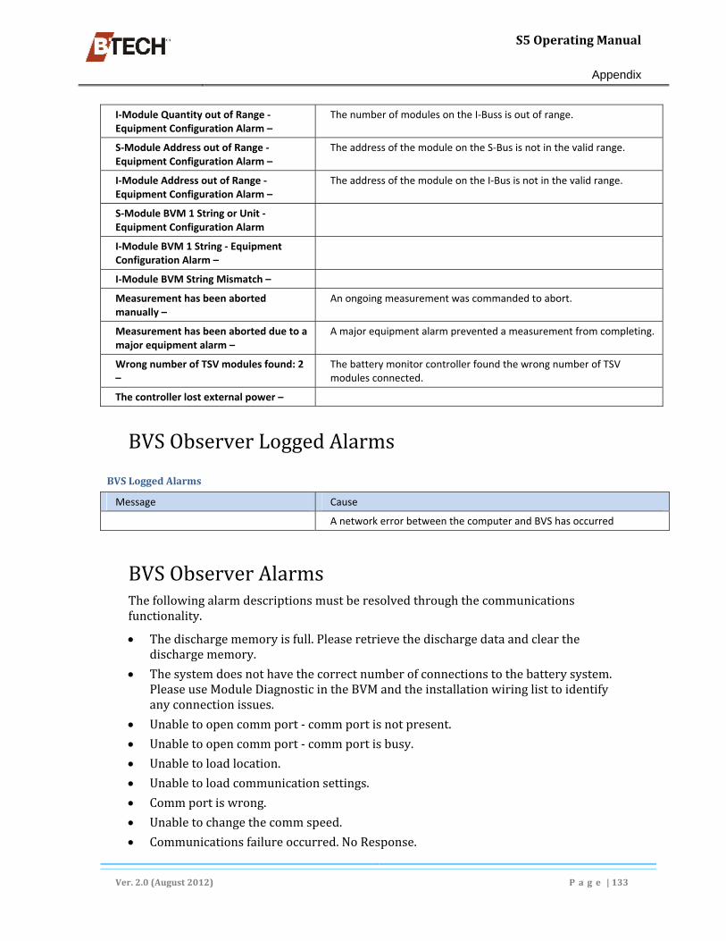
S5OperatingManual
Appendix
Ver.2.0(August2012) P a g e |133
I‐Module Quantity out of Range ‐ Equipment Configuration Alarm –
The number of modules on the I‐Buss is out of range.
S‐Module Address out of Range ‐ Equipment Configuration Alarm –
The address of the module on the S‐Bus is not in the valid range.
I‐Module Address out of Range ‐ Equipment Configuration Alarm –
The address of the module on the I‐Bus is not in the valid range.
S‐Module BVM 1 String or Unit ‐ Equipment Configuration Alarm
I‐Module BVM 1 String ‐ Equipment Configuration Alarm –
I‐Module BVM String Mismatch –
Measurement has been aborted manually –
An ongoing measurement was commanded to abort.
Measurement has been aborted due to a major equipment alarm –
A major equipment alarm prevented a measurement from completing.
Wrong number of TSV modules found: 2 –
The battery monitor controller found the wrong number of TSV modules connected.
The controller lost external power –
BVSObserverLoggedAlarms
BVSLoggedAlarms
Message Cause
A network error between the computer and BVS has occurred
BVSObserverAlarmsThefollowingalarmdescriptionsmustberesolvedthroughthecommunicationsfunctionality.
Thedischargememoryisfull.Pleaseretrievethedischargedataandclearthedischargememory.
Thesystemdoesnothavethecorrectnumberofconnectionstothebatterysystem.PleaseuseModuleDiagnosticintheBVMandtheinstallationwiringlisttoidentifyanyconnectionissues.
Unabletoopencommport‐commportisnotpresent.
Unabletoopencommport‐commportisbusy.
Unabletoloadlocation.
Unabletoloadcommunicationsettings.
Commportiswrong.
Unabletochangethecommspeed.
Communicationsfailureoccurred.NoResponse.

S5OperatingManual
Appendix
Ver.2.0(August2012) P a g e |134
LocationID'sdidnotmatch.
WrongController.
Numberofstringsdidnotmatch.
Numberofunitsdidnotmatch.
Modelnumberdoesnotmatch.
Thenumberoftemperaturesensorsdidnotmatch.
Theserialnumbersdidnotmatch.
TheBVSisbusymeasuringimpedance.
TheBVSisbusytakingdischargemeasurements.
Errorretrievingdischargemeasurements.
Noresponsefrommodem.
Numberbusy.
ModemError.
NoDialtone.
DialTimedOut.
NoAnswer.
NoCarrier.
Errorretrievingmeasurmentdata.
Phonenumberismissing.
Dialmodemnotavailableoncommport.
Networkconnectiontimeout.
PermissonDenied.
Theaddressisalreadyinuse.
Theaddressisnotavailable.
Addressfamilynotsupportedbyprotocolfamily.
Operationalreadyinprogress.
Networkconnectionhasaborted.
Connectionrefused.
Networkconnectionhasreset.
Destinationaddressrequired.
Badaddress.
Noroutetohost.
Operationnowinprogress.
Interruptedfuntioncall.
Invalidargument.
Socketisalreadyconnected.
Toomanyopensockets.
Messagetoolong.

S5OperatingManual
Appendix
Ver.2.0(August2012) P a g e |135
Networkisdown.
Networkconnectionwasreset.
Thenetworkcannotbereachedfromthishostatthistime.
Nobufferspaceavailable.
Socketisnotconnected.
Networkconnectionhasclosed.
Socketoperationonnon‐socket.
Protocolfamilynotsupported.
Toomanyprocesses.
Protocolnotsupported.
Protocolwrongtypeforsocket.
Networkconnectionhasshutdown.
Sockettypenotsupported.
Attempttoconnecttimedoutwithoutestablishingaconnection.
Hostnotfound.
Networkinitializationnotsuccessful.
Thisisnon‐recoverableerror.
Networksubsystemisunavailable.

S5OperatingManual
Appendix
Ver.2.0(August2012) P a g e |136
SNMPManagerDescriptionandConfigurationBVM4.xallowsanSNMPmanagertouseanS5asanSNMPagent.TheS5includesanSNMPmodelwebservercapableofrespondingto“Get”and“GetNext”requests,andsendingunsolicited‘trap’messages.
Asanagent,theS5listensonUDPport161forSNMPmessagesfromthemanager.WhentheS5BVSencountersanalarminthebatterysystem,aSNMPtrapissentout.ConfigurationofIPaddressesthatreceivetheSNMPtrap,andtheresendintervalisprovided.OptionallyuptothreeIPaddressescanreceiveatrap.
.mib Files
AMIB(ManagementInformationBase)file,namedBTECHBatteryMonitorS5.mibisprovided.AllobjectsprovidedanddefinedintheMIBfileareintheenterprisesubtree.Thesetofobjectsinthealarmdirectorydescribeanalarmasanobject’s:
Severity,
Description,
Type,
Year,
Month,
Day,
Hour,Minute,Second,
String,
Unit.
TheS5BVSsendsaSNMPtrapwhenanalarmoccurswhichisboundwiththeseobjectssotheSNMPmanagercandetermineacourseofaction.Ifmorethanonealarmoccursatagiventime,multipletrapsaresenttothemanager.Eachtrapdescribesonealarm.Oneoftheobjectsboundtothetrapiscalled“Severity”.TheS5BVSdefinesthisobjectasoneofthefollowing:
1=Critical–immediateactionneeded,pagesomeoneevenafterhours
2=Major–actionneededsoon,ifafterhours,nextbusinessdaywilldo
4=Minor–actioncouldprobablywaitfornextmaintenancewindow
8=Warning–informative,sometimesrequireaction
ThereisoneobjectintheMIBtreethatindicatesifotherapplications,suchasBTECH’sBVM4.x,BTECH’sObserverprogram,oraMODBUSmaster,areconnectedtotheS5BVS.TheSNMPmanagercanstillaccessSNMPobjectsbuttheobjectsortrapswillnotbeavailableatthistime.TheS5BVScanbeconfiguredtoautomaticallyconnecttoanObserverapplicationwhenanalarmoccurs.TheObserverretrievesthealarmsand,ifset,canclearthealarms.Inthisscenario,theS5BVSwillatleastsendoutonetrapbeforeconnectingtotheobserver.
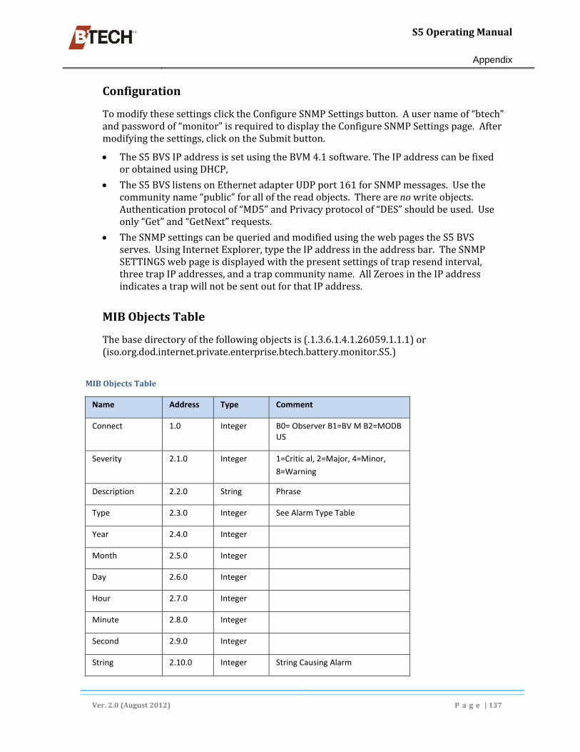
S5OperatingManual
Appendix
Ver.2.0(August2012) P a g e |137
Configuration
TomodifythesesettingsclicktheConfigureSNMPSettingsbutton.Ausernameof“btech”andpasswordof“monitor”isrequiredtodisplaytheConfigureSNMPSettingspage.Aftermodifyingthesettings,clickontheSubmitbutton.
TheS5BVSIPaddressissetusingtheBVM4.1software.TheIPaddresscanbefixedorobtainedusingDHCP,
TheS5BVSlistensonEthernetadapterUDPport161forSNMPmessages.Usethecommunityname“public”forallofthereadobjects.Therearenowriteobjects.Authenticationprotocolof“MD5”andPrivacyprotocolof“DES”shouldbeused.Useonly“Get”and“GetNext”requests.
TheSNMPsettingscanbequeriedandmodifiedusingthewebpagestheS5BVSserves.UsingInternetExplorer,typetheIPaddressintheaddressbar.TheSNMPSETTINGSwebpageisdisplayedwiththepresentsettingsoftrapresendinterval,threetrapIPaddresses,andatrapcommunityname.AllZeroesintheIPaddressindicatesatrapwillnotbesentoutforthatIPaddress.
MIBObjectsTable
Thebasedirectoryofthefollowingobjectsis(.1.3.6.1.4.1.26059.1.1.1)or(iso.org.dod.internet.private.enterprise.btech.battery.monitor.S5.)
MIBObjectsTable
Name Address Type Comment
Connect 1.0 Integer B0= Observer B1=BV M B2=MODB US
Severity 2.1.0 Integer 1=Critic al, 2=Major, 4=Minor,
8=Warning
Description 2.2.0 String Phrase
Type 2.3.0 Integer See Alarm Type Table
Year 2.4.0 Integer
Month 2.5.0 Integer
Day 2.6.0 Integer
Hour 2.7.0 Integer
Minute 2.8.0 Integer
Second 2.9.0 Integer
String 2.10.0 Integer String Causing Alarm

S5OperatingManual
Appendix
Ver.2.0(August2012) P a g e |138
Name Address Type Comment
Unit 2.11.0 Integer Unit Causing Alarm

S5OperatingManual
Appendix
Ver.2.0(August2012) P a g e |139
ModbusMessaging–S5[‐ML]BatteryValidationSystemThisS5featureallowsaplantcomputer(DCS)tomonitorthemeasurementstakenbytheS5.TheDCScommunicateswiththeS5overanEthernetconnectionusingtheMODBUSoverTCP/IPprotocol.TheplantDCSreadsanddisplaysthefollowingmeasurementstakenbytheS5:
Systemvoltages
Systemcurrent
StringCurrents/Voltages
Ambienttemperature
Unitfloatvoltage
Unittemperature
UnitImpedance
AssoonastheMODBUSMasterconnects,itsholdingregistersforUnitImpedancearethevaluestakenatthelastimpedanceread.Measurements(#1thru#6)arethenupdatedtotheMODBUSholdingregisterseverytimetheVTz3modulesarescanned.ThisupdatehappensevenwhentheS5isindischargemode.
UnitImpedanceisupdatedtotheMODBUSholdingregistersatarateconfiguredbytheuser.Duringanimpedancemeasurement,measurementsnumbered1through6arenotupdated.ThereareacoupleofMODBUSregistersthatindicatewhenthelastimpedancemeasurementwastaken.
Comments
Alldatavaluesaresuppliedtotheregisterspre‐scaled.
LoggedDischargedataisNOTreportedviaMODBUS.
AllMODBUSholdingregistersarereadonly,meaningtheDCScanonlyinterrogatetheS5butnotconfigureit.NeithercantheDCSclearalarmsintheS5viaMODBUS.AllconfigurationsandalarmresetsaredonewiththeBVMsoftwarethroughanotherS5connection.TheDCScanexamineacoupleofMODBUSregistersthatindicatehowtheS5wasconfigured.Theyare:
location,
numberofstrings,and
unitsperstring.
Additional Measurement Registers
Inadditiontotheabovemeasurements,theS5–MLalsoletstheDCSobtainstatusoftheS5throughthefollowingoutputcoilregisters.
MaintenanceAlarm
CriticalAlarm
Equipmenterror
InDischarge
Impedancemeasurementinprogress
Dischargememoryfull

S5OperatingManual
Appendix
Ver.2.0(August2012) P a g e |140
Alarm Registers
TheS5‐MLupdatesasetofregistersifanalarmoccurs.Thelast32alarmscanbemonitoredbytheDCS.However,oncethe32alarmregistersarefilled,theS5‐MLcannotacceptadditionalalarms.ThealarmscanonlybeclearedbyusingtheBVMsoftware.
TheS5‐MLcanreportanalarmtoanOBSERVERthatisconnectedtothenetwork.ThesocketconnectiontotheMODBUSmasterremainsopenduringtheconversationfromtheS5‐MLtotheOBSERVER.
TheBVMsoftwarecanconnecttotheS5‐MLwhiletheMODBUSmasterisalsoconnected.ThesocketconnectiontotheMODBUSmasterremainsopenduringtheconversationfromtheS5‐MLtotheBVMsoftware.
See
AlarmDefinitions,page141
Configuration
TheS5IPaddressissetupwithintheBVMSoftware.ItcanbeafixedIPaddressorobtainedfromaDHCPserver.TheS5hasafixedportaddress(502)forMODBUS.TheMODBUSslaveaddressis1.Onpower‐up,theS5openstwosocketsforeithertheBVMsoftwareortheDCS.
S5‐ML Location Registers and Addresses
TheS5‐MLcanbeconfiguredtohaveatmost4locations.
Location1:addoffsetof0toholdingRegisters,and0toCoiladdresses(Sameasaddressesintable).
Location2:addoffsetof1000toholdingRegisters,andoffsetof20toCoiladdresses.
Location3:addoffsetof2000toholdingRegisters,andoffsetof30toCoiladdresses.
Location4:addoffsetof3000toholdingRegisters,and40toCoiladdresses.
MODBUSRegisters
Name Address Type CommentLocation 40001 Integer NumberofStrings 40002 Integer NumberUnitsperString 40003 Integer SystemVoltage 40004 Float (volts)SystemCurrent 40006 Float (a)AmbientTemperature 40008 Float (degc)StringCurrent1 40010 Float (a)StringCurrent2 40012 Float (a)StringCurrent3 40014 Float (a)
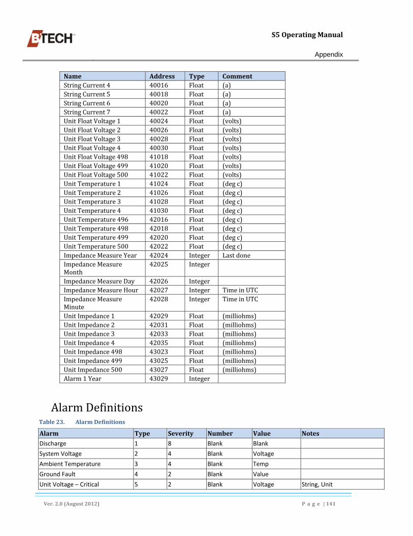
S5OperatingManual
Appendix
Ver.2.0(August2012) P a g e |141
Name Address Type CommentStringCurrent4 40016 Float (a)StringCurrent5 40018 Float (a)StringCurrent6 40020 Float (a)StringCurrent7 40022 Float (a)UnitFloatVoltage1 40024 Float (volts)UnitFloatVoltage2 40026 Float (volts)UnitFloatVoltage3 40028 Float (volts)UnitFloatVoltage4 40030 Float (volts)UnitFloatVoltage498 41018 Float (volts)UnitFloatVoltage499 41020 Float (volts)UnitFloatVoltage500 41022 Float (volts)UnitTemperature1 41024 Float (degc)UnitTemperature2 41026 Float (degc)UnitTemperature3 41028 Float (degc)UnitTemperature4 41030 Float (degc)UnitTemperature496 42016 Float (degc)UnitTemperature498 42018 Float (degc)UnitTemperature499 42020 Float (degc)UnitTemperature500 42022 Float (degc)ImpedanceMeasureYear 42024 Integer LastdoneImpedanceMeasureMonth
42025 Integer
ImpedanceMeasureDay 42026 Integer ImpedanceMeasureHour 42027 Integer TimeinUTCImpedanceMeasureMinute
42028 Integer TimeinUTC
UnitImpedance1 42029 Float (milliohms)UnitImpedance2 42031 Float (milliohms)UnitImpedance3 42033 Float (milliohms)UnitImpedance4 42035 Float (milliohms)UnitImpedance498 43023 Float (milliohms)UnitImpedance499 43025 Float (milliohms)UnitImpedance500 43027 Float (milliohms)Alarm1Year 43029 Integer
AlarmDefinitionsTable23. AlarmDefinitions
Alarm Type Severity Number Value NotesDischarge 1 8 Blank Blank
System Voltage 2 4 Blank Voltage
Ambient Temperature 3 4 Blank Temp
Ground Fault 4 2 Blank Value
Unit Voltage – Critical 5 2 Blank Voltage String, Unit

S5OperatingManual
Appendix
Ver.2.0(August2012) P a g e |142
Alarm Type Severity Number Value NotesUnit Voltage ‐ Maintenance 6 4 Blank Voltage String, Unit
Unit Impedance Average ‐ Critical 7 2 Blank Impedance String, Unit
Unit Impedance Average ‐ Maintenance
8 4 Blank Impedance String, Unit
Unit Impedance Initial ‐ Critical 9 2 Blank Impedance String, Unit
Unit Impedance Initial ‐ Maintenance
10 4 Blank Impedance String, Unit
Unit Temperature 11 4 Blank Temp String, Unit
Unit Temperature ‐ Differential 12 4 Blank Temp Difference String, Unit
String Voltage 13 4 Blank Voltage String #
Aux Alarm [Relay outputs] 1 14 4 Blank Blank
Aux Alarm [Relay outputs] 2 15 2 Blank Blank
Aux Alarm [Relay outputs] 3 16 2 Blank Blank
Aux Alarm [Relay outputs] 4 17 2 Blank Blank
Wrong Number of Voltage Modules
18 2 Number Blank
Wrong Number of Discharge Current Modules
19 2 Number Blank
Communication Error with Voltage Module
20 2 Module # Blank
Communication Error with Current Module
21 2 Module # Blank
Unknown Type of Module 22 2 Module # Blank
Corrupted Configuration 23 2 Reason Blank 1 = Bad checksum 2 = Value out of limits
Hardware Failure 24 2 Serial port Blank 1 = Network or front panel 2 = Modem 3 = Module port
Backup Battery 25 2 Blank Voltage
Module Initialization Failure 26 4 Physical probe position
Modem Failure 27 2
Modem Line Failure 28 2
Invalid Communication’s Configuration
29 2
Network controller is missing 30 2
Number of units found is not equal to the amount specified. (voltage modules)
31 2 Module # # of Voltages found
Number of temperatures found is not equal to the amount specified. (voltage and temp module)
32 2 Module # # of Temperatures found

S5OperatingManual
Appendix
Ver.2.0(August2012) P a g e |143
Alarm Type Severity Number Value NotesTemperature Sensor 33 2 Sensor Number Temperature
Temperature Sensor – Differential 34 2 Sensor Number Temperature Difference
Module Relearn Connection Failure
35 2 Module #
Impedance measurement aborted due to high voltage on positive half string.
101 8 Voltage
Impedance measurement aborted due to low voltage on positive half string.
102 8 Voltage
Impedance measurement aborted due to high voltage on negative half string.
103 8 Voltage
Impedance measurement aborted due to low voltage on negative half string.
104 8 Voltage
Impedance measurement aborted due to high load plate temperature.
105 8 Temp
Impedance measurement aborted due to discharge
106 8

S5OperatingManual
Product Warranty
Ver.2.0(August2012) P a g e |144
Product Warranty NOTE:THISWARRANTYISGIVENTOTHEORIGINALPURCHASINGENDUSERANDISAPPLICABLEONLYTOPRODUCTSANDLICENSEDMATERIALSSOLDORDISTRIBUTEDTOSUCHENDUSERBYANAUTHORIZEDBTECHRESELLER,ORBTECHINC.ANDBEARINGTHE“BTECH”BRANDNAME.
A. Hardware Warranty
BTECHwarrantstotheoriginalpurchasingEndUserthateachunitofBTECHhardwareproducts(“HardwareProducts”or“Products”)willbefreefromdefectsinmaterialandworkmanshipforaperiodofone(1)yearfromthedateofshipmenttoEndUser.
Thewarranty periodwill be defined as (15) fifteenmonths from shipment or (1) one year from startup,whichevercomesfirst.
BreachofwarrantywillbeenforceableagainstBTECHonlyifwrittennoticeofsuchbreachisreceivedbyBTECHwithintheapplicablewarrantyperiod.
Ifawarrantyclaimisinvalidforanyreason,theEndUserwillbechargedforservicesperformedandexpensesincurredbyBTECHinrepairing,handlingandshippingthereturnedProduct.
Expendableparts,suchasfusesandotherpartsthatareregularlyreplacedduetonormaluse,areexcludedfromthiswarranty.
AstoProductsrepairedorreplacedduringtheoriginalwarrantyperiodforsuchProduct,thewarrantyperiodonthereplacementProductortherepairedProductshallterminatethirty(30)daysaftershipmenttoEndUserorupontheterminationoftheoriginalwarrantyperiod,whicheverislonger.
Astoanyout‐of‐warrantyProductsrepaired,modifiedorreplacedbyBTECHatBTECHregularcharges,thewarrantyperiodwithrespecttothematerialandworkmanshiphereundershallexpirethirty(30)daysafterthedateofshipmentofsaidProducttoEndUser.
B. Software Warranty TheonlywarrantyBTECHmakestoEndUserinconnectionwithBTECHlicensedmaterials,whichincludesBTECHsoftware,togetherwithrelateddocumentationandthemediaembodyingthesoftware(“LicensedMaterials”),isthatthemediaonwhichtheLicensedMaterialsarerecordedwillbereplacedwithoutcharge,ifBTECH,ingoodfaith,determinesthatthemediawasdefectiveandnotsubjecttomisuseforaperiodofninety(90)daysfromthedateofshipmenttoEndUser.Withinthirty(30)daysofdeterminationofsame,BTECHshallusecommerciallyreasonableeffortstoreplaceanydefectivemediathatBTECHhasdeterminedtobeunderwarranty.
C. Entitlement During the Applicable Warranty Period
Technical Support
TechnicaltelephonesupportwillbeprovidedbyBTECHFactoryTechnicalServiceAssistanceCentertoEndUserfrom8:00a.m.to5:00p.m.ESTMondaythroughFriday,excludingholidays.Telephonesupportprovidedhereunderwillbelimitedtothatnecessarytoconfirmfunctional

S5OperatingManual
Product Warranty
Ver.2.0(August2012) P a g e |145
operationordetermineifaProductisperforminginaccordancewithSectionAorBabove,whicheverapplies.Shouldfurthersupportberequired,normalsupportchargeswillapply.
Firmware/Software for the Version Licensed
ShouldBTECHFactoryServicedetermine,duringthecourseofprovidingsupporthereunder,thattheEndUsermaybenefitfromtheinstallationofafirmwarepatch,upgradeorsoftwarebugfix,ifandwhenBTECH,atitssolediscretion,developsandreleasessaidfirmwarepatch,orupgrade,orsoftwarebugfix,BTECHmaymakesameavailabletotheEndUseratnocharge.
Product Replacement
Duringtheinitialthirty(30)daysfromthedateofshipmentofHardwareProductshavingaone(1)yearwarrantyhereunder,suchHardwareProductswhich,afterreasonableduediligenceandsupportattemptsbyBTECHFactoryService,isdeterminedbyBTECHFactoryServicetobenon‐functioningduetoproductdefect,shallbereplacedonacommerciallyreasonableeffortsbasis.BTECHandEndUserwillfollowtheproceduresoutlinedinSectionChereinforthereturnandreplacementofsuchHardwareProductsduringtheabovereferencedperiodsthatEndUserhaspurchaseddirectlyfromBTECH.ForsuchHardwareProductsthatEndUserhaspurchasedfromaBTECHReseller,thefollowingproceduresshallbefollowedforthereturnandreplacementofsuchHardwareProductsduringtheabovereferencedperiods:
BTECHmustbenotifiedbyEndUserpriortothereturnofsaidProduct.Withinten(10)daysofthedateofsaidnotificationBTECHwillprovideEndUserwithavalidReturnMaterialAuthorizationNumber(RMA).
b)Withinten(10)daysofreceiptofaReturnMaterialAuthorizationNumberfromBTECH,theEndUserwillnotifytheResellerfromwhomtheProductwaspurchasedoftheRMANumber,requestProductreplacement,andobtaininformationregardingthelocationtowhichtheEndUsermustreturntheProductclaimedtobedefective,aswellasanyotherpertinentinformation.
TransportationcostsrelatingtothedeliveryofwarrantyclaimstoResellerwillbebornebytheEndUser.InnoeventwillReselleracceptanyreturnedProductthatdoesnothaveavalidRMANumber.AllProductsreturnedtoResellermustbepackagedinpackingmaterialsthataffordsthesamedegreeofprotectionfromdamageandelectricaldischargeastheoriginalpackagingmaterials.
AllProductsreturnedtoResellershouldbeconfiguredasoriginallyshippedtoEndUserbyremovingalladd‐onhardware.Add‐onhardwarereturnedwiththeProductsmaybelostintherepairprocess,andResellershallbearnoresponsibilityforsuchloss.
EndUsershallpromptly,butinnoeventlaterthanten(10)daysofreceiptofanRMANumberfromBTECH,deliversaidshipmenttoacarrieratEndUser’sfacilitiesaspreviouslystated.
Withinthirty(30)daysofreceiptofsame,ResellershallusecommerciallyreasonableeffortstoreplaceanydefectiveProductsthatBTECHorResellerhasdeterminedtobeunderwarranty.
TransportationcostsrelatingtothereturnofwarrantyclaimstotheEndUserwillbebornebyReselleronlyincaseswherereplacementismadeandauthorizedpursuanthereto,butanyapplicabledutiesortaxeswillbepaidbyEndUser.Ifnowarrantyreplacementwasrequired,alltransportationcostswillbebornebyEndUser.“Emergency”transportationcostsshallbebornebyEndUser.

S5OperatingManual
Product Warranty
Ver.2.0(August2012) P a g e |146
Return and Repair
Duringtheremainderofthehardwarewarrantyperiod,ifProductsunderwarrantyareclaimedtobedefective,BTECHmustbenotifiedbyEndUserpriortothereturnofsaidProduct.Withinten(10)daysofthedateofsaidnotificationBTECHwillprovideEndUserwithavalidReturnMaterialAuthorizationnumberandthelocationtowhichEndUsermustreturntheProductclaimedtobedefective.TransportationcostsrelatingtothedeliveryofwarrantyclaimstoBTECHwillbebornebytheEndUser.InnoeventwillBTECHacceptanyreturnedProductwhichdoesnothaveavalidReturnMaterialAuthorizationnumber.AllProductsreturnedtoBTECHshouldbeconfiguredasoriginallyshippedtoEndUserbyremovingalladd‐onhardware.Anyadd‐onhardwarereturnedwiththeProductsmaybelostintherepairprocess,andBTECHshallbearnoresponsibilityforsuchloss.
Withinthe(10)daysofreceiptofnoticefromBTECHrequiringreturn,EndUsershalldeliversaidshipmenttoacarrieratEndUser’sfacilitiesasaforesaid.
Withinthirty(30)daysofreceiptofsame,BTECHshallusecommerciallyreasonableeffortstofixorreplace,atitsoption(exceptasprovidedinSectionCherein),anydefectiveProductsthatBTECHhasdeterminedtobeunderwarranty.
TransportationcostsrelatingtothereturnofwarrantyclaimstotheEndUserwillbebornebyBTECHonlyincaseswhererepairorreplacementismadeandauthorizedpursuanthereto,butanyapplicabledutiesortaxeswillbepaidbyEndUser.Ifnowarrantyrepairorreplacementwasrequired,alltransportationcostswillbebornebyEndUser.“Emergency”transportationcostsshallbebornebyEndUser.
General
ThewarrantiessetforthinSectionsAandBabove,andtheentitlementssetforthinSectionCabove,areforthebenefitofandshallapplyonlytoEndUser.
BTECHwarrantiesshallnotapplytoanyProductorLicensedMaterialwhichhasbeendamagedasaresultof,orsubjectedto,accident,neglect,misuse,abuse,vandalism,riot,war,actsofterrorism,negligenceintransportationorhandling,failureorsurgesinelectricpower,airconditioning,humiditycontrol,flood,water,fireorsmokeandheatdamage,causesotherthanordinaryuse,actsofGodorcausesbeyondBTECHcontrol,oriftheProductorLicensedMaterialwasnotproperlymaintainedbyEndUserduringthewarrantyperiod.
ThereshallbenowarrantyorliabilityforanyProductsorLicensedMaterialsthathavebeenmodifiedbyEndUserwithoutBTECHpriorwrittenapproval.
ReplacementProductsorLicensedMaterialsoutsidethescopeofthiswarrantyorwithrespecttoProduct(s)orLicensedMaterialsout‐of‐warrantywillbefurnishedattheestablishedchargesofBTECHthenineffect.EndUsershallensurethatBTECHwillhavefullandfreeaccesstotheProductsandLicensedMaterialsandEndUser’ssite,ifrequired.BTECHshallnotberesponsibleforfailuretorepairorreplaceProductsorLicensedMaterialsduetocausesbeyonditscontrol.BTECHshallnotberequiredtoreplaceanyProductorLicensedMaterialifitwouldbeimpracticalforBTECHpersonneltodosobecauseofunauthorizedalterationstotheProductsorLicensedMaterialsoritsunauthorizedconnectionbymechanicalorelectricalmeanstoanothersystemordevice.

S5OperatingManual
Product Warranty
Ver.2.0(August2012) P a g e |147
Limitation of Liability
THESEWARRANTIESANDBTECHANDITSAFFILIATES’LIABILITYANDENDUSER’SREMEDIESWITHRESPECTTHERETO,ASSETFORTHHEREIN,AREEXCLUSIVEANDEXPRESSLYINLIEUOFALLOTHERWARRANTIES,LIABILITIES,REMEDIES,EXPRESSORIMPLIED,INCLUDINGANYOBLIGATION,LIABILITY,RIGHT,CLAIMORREMEDYINTORT,WHETHERORNOTARISINGFROMNEGLIGENCEOFBTECHORITSAFFILIATES,ACTUALORIMPUTED,ANDNOWARRANTIES,EXPRESSORIMPLIEDREPRESENTATIONS,PROMISESORSTATEMENTSHAVEBEENMADEBYBTECHORITSAFFILIATESUNLESSCONTAINEDINTHISAGREEMENT.NOWARRANTY,EXPRESSORIMPLIED,ISMADEHEREINTHATTHELICENSEDMATERIALS,PRODUCTSORANYPARTSAREMERCHATABLE,ORFITORSUITABLEFORTHEPARTICULARPURPOSESFORWHICHTHELICENSEDMATERIALS,PRODUCTSORPARTSMAYBEACQUIREDBYENDUSER.INNOEVENTSHALLBTECHORITSAFFILIATESBELIABLETOENDUSERFORANYINDIRECT,INCIDENTAL,ORCONSEQUENTIALDAMAGESINCLUDINGWITHOUTLIMITATION,LOSSOFDATA,ORPROFITS,WHETHERCLAIMEDBYREASONOFBREACHOFWARRANTYOROTHERWISE,ANDWITHOUTREGARDTOTHEFORMOFACTIONINWHICHSUCHCLAIMISMADE.
TheProductsandLicensedMaterialsarenotspecificallydeveloped,orlicensedforuseinanynuclear,aviation,masstransit,ormedicalapplicationsorinanyotherinherentlydangerousapplications.
EndUseragreestoindemnifyandholdBTECHharmlessfromanyclaimsforlosses,costs,damages,orliabilityarisingoutoforinconnectionwiththeuseoftheProductsand/orLicensedMaterialsinsuchapplications.
Notwithstandinganythingcontainedhereintothecontrary,thetotalmaximumliabilityofBTECHanditsAffiliatesunderthiswarrantyfortheaffectedProduct(s)andLicensedMaterialsislimited,attheoptionofBTECH,toeither:
BTECHuseofreasonableeffortstorepairanyProductorLicensedMaterials;orBTECHuseofreasonableeffortstoreplaceanyProductorLicensedMaterials,oranyshipmentastowhichanydefectisclaimedbyEndUseranddulyverifiedbyBTECH;or
Therefundofthepurchasepriceorlicensefeepaid.


