19
1 RocketRAID 2720C2 User Manual V1.00 Nov. 25, 2013

1
RocketRAID 2720C2
User Manual
V1.00
Nov. 25, 2013

2
Table of contents
HighPoint RocketRAID 2720C2 -Cross-Sync RAID Solution . . . . . . . . . . . . . . . . . . . . . . . . . . 3
1. Kit Contents . . . . . . . . . . . . . . . . . . . . . . . . . . . . . . . . . . . . . . . . . . . . . . . . . . . . . . . . . . . . . . . . . . . . . . . . 3
2. Installing the RocketRAID 2720C2 Host Adapters . . . . . . . . . . . . . . . . . . . . . . . . . . . . . . 3
3. Prepare the RocketRAID 2720C2 . . . . . . . . . . . . . . . . . . . . . . . . . . . . . . . . . . . . . . . . . . . . . . . . . 4
4. RocketRAID Series Controller BIOS Utility . . . . . . . . . . . . . . . . . . . . . . . . . . . . . . . . . . . . . 5
4.1 BIOS Settings Overview . . . . . . . . . . . . . . . . . . . . . . . . . . . . . . . . . . . . . . . . . . . . . 5
4.2 Using the BIOS Util ity . . . . . . . . . . . . . . . . . . . . . . . . . . . . . . . . . . . . . . . . . . . . . . . 6
4.3 BIOS Commands . . . . . . . . . . . . . . . . . . . . . . . . . . . . . . . . . . . . . . . . . . . . . . . . . . . . . . . 6
4.4 Creating RAID Arrays . . . . . . . . . . . . . . . . . . . . . . . . . . . . . . . . . . . . . . . . . . . . . . . 7
4.5 Delete Arrays . . . . . . . . . . . . . . . . . . . . . . . . . . . . . . . . . . . . . . . . . . . . . . . . . . . . . . . . . . 11
4.6 Add/Remove Spare Disks . . . . . . . . . . . . . . . . . . . . . . . . . . . . . . . . . . . . . . . . . . 12
4.7 Settings . . . . . . . . . . . . . . . . . . . . . . . . . . . . . . . . . . . . . . . . . . . . . . . . . . . . . . . . . . . . . . . . . . 13
4.8 View . . . . . . . . . . . . . . . . . . . . . . . . . . . . . . . . . . . . . . . . . . . . . . . . . . . . . . . . . . . . . . . . . . . . . . . 14
5. Driver Installation (Windows) . . . . . . . . . . . . . . . . . . . . . . . . . . . . . . . . . . . . . . . . . . . . . . . . . . 15
6. WebGUI Installation (Windows) . . . . . . . . . . . . . . . . . . . . . . . . . . . . . . . . . . . . . . . . . . . . . . . . 15
7. Driver Installation (Linux) . . . . . . . . . . . . . . . . . . . . . . . . . . . . . . . . . . . . . . . . . . . . . . . . . . . . . . 16
8. WebGUI Installation (Linux) . . . . . . . . . . . . . . . . . . . . . . . . . . . . . . . . . . . . . . . . . . . . . . . . . . . 16
9. Starting the WebGUI . . . . . . . . . . . . . . . . . . . . . . . . . . . . . . . . . . . . . . . . . . . . . . . . . . . . . . . . . . . . 16
10. Using the WebGUI . . . . . . . . . . . . . . . . . . . . . . . . . . . . . . . . . . . . . . . . . . . . . . . . . . . . . . . . . . . . . . 16
11. Customer Support and Contact Information . . . . . . . . . . . . . . . . . . . . . . . . . . . . . . . . . . . 18
FCC Part 15 Class B Radio Frequency Interference statement . . . . . . . . . . . . . . . . . . . . . . . 19

3
HighPoint RocketRAID 2720C2 -Cross-Sync RAID Solution
HighPoint’s 6Gb/s Cross-Sync RAID Solution aims to revolutionize DAS applications. Cross-Sync
synchronizes up to two RocketRAID 2720C2 controller cards to work as a single RAID storage
unit. The Cross-Sync RAID Solution provides 16 SAS/SATA6Gb/s Ports over a Dual PCIe x8
Host Interface, and is capable of delivering up to 4GB/s of transfer performance!
Key Features:
Up to 4GB/s Transfer Performance!
Enables arrays to be created using up to 2x RAID 2720C2 HBA's
16x SAS/SATA 6Gb/s Ports across Dual PCIe 2.0 x8 Transfer Bandwidth
1. Kit Contents
RocketRAID 2720C2 x2
Low profile bracket x2
Quick Installation Guide
2. Installing the RocketRAID 2720C2 Host Adapters
Note: Make sure the system is powered-off before installing the RocketRAID host adapters.
1) Open the system chassis and locate two unused PCI-Express (2.0 or 1.0) x8 slots.
2) Remove the PCI slot cover.
3) Gently insert the RocketRAID host adapters into the PCI-Express slots, and secure the
brackets to the system chassis.
4) After installing the each adapter, attach the hard disks or disk enclosure to the RocketRAID
card using the SAS or SATA cables.
5) Close and secure the system chassis.
4
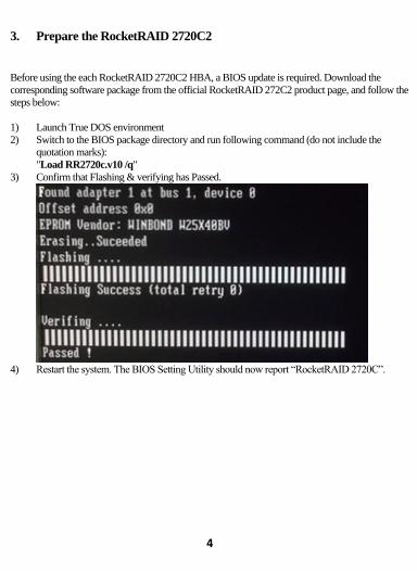
3. Prepare the RocketRAID 2720C2
Before using the each RocketRAID 2720C2 HBA, a BIOS update is required. Download the
corresponding software package from the official RocketRAID 272C2 product page, and follow the
steps below:
1) Launch True DOS environment
2) Switch to the BIOS package directory and run following command (do not include the
quotation marks):
"Load RR2720c.v10 /q"
3) Confirm that Flashing & verifying has Passed.
4) Restart the system. The BIOS Setting Utility should now report “RocketRAID 2720C”.

5
4. RocketRAID Series Controller BIOS Utility
The RocketRAID series controller will display its BIOS screen during the system's boot process.
The BIOS Utility will display information about hard drives attached to the adapter. Make sure all
attached drives are detected by this utility. If any of the hard drives are not detected, power down the
system and check the power and cable connections.
Press the “Ctrl+H” key combination to access the controller ’s BIOS
Uti l i ty .
4.1 BIOS Settings Overview
The RocketRAID controller BIOS utility is an interface that provides management commands and
controller related settings.

6
4.2 Using the BIOS Utility
The following keys utilized by the RocketRAID series controller BIOS utility:
Arrow keys – Use these to move between different menu items.
Enter – Open the selected toolbar command/execute the selected command.
Esc – Move back to the previous menu, cancel the selected operation, or exit the BIOS Utility.
4.3 BIOS Menu Commands
Create – This command is used to open the RAID Creation menu.
Delete – This command will delete the selected RAID array.
Add/Remove Spare – This command is used to assign hard disks to function as spare disks. The
controller is capable of using spare disks to automatically rebuild broken or faulted RAID arrays.
Settings – This command opens the settings menu (To selecting the boot disk/array, parameter
setting etc.)
View – This command is used to view controller, hard disk and RAID Array information.
Initialize – This command is used to prepare disks for use with RAID arrays. Disks must be
initialized before they can be used to create arrays.

7
4.4 Creating RAID Arrays
Initializing Disks:
All the single disks attached to the RocketRAID controller will be marked as “Legacy” status. A
Legacy disk will be report to operating system as single disk. The Legacy disks must be initialized
before creating a RAID array. To initialized disk, select the Initialize command from the toolbar,
and press the Enter key.
BIOS utility will list all single Legacy disks attached to the RocketRAID controller as below:
Channel: This column identifies each disk attached to the controller (host adapter). It is used to help
identify each disk’s location. The first digit represents the controller (which host adapter the selected
disk is attached to). The second digit represents the disk’s port number (which port number the
selected disk is attached to). If multiple controllers are installed (more than one host adapter card),
the first controller will be designated as “1”, the second controller as “2”, and so on.
For Example:
“1-2” = Controller #1, Port #2
“2-3” = Controller #2, Port #3
Model Number: This column shows the disk model.
Capacity (GB): This column shows the disk capacity.

8
Mode: This column shows the current disk type and link speed. The disk running mode is
depending on the RocketRAID controller mode and disk mode.
Status: This column shows the disk status. In this section, there will be only Legacy status.
Highlight the target disks with the arrow keys, and then press the Enter key. A numeral will be
displayed before each selected disk. Once all target disks have been selected, press the ESC key.
The utility will display a warning, and ask you to press Y (yes) to initialize, or N (no) to cancel.
Once initialized, these disks can be used to create RAID arrays.
Warning: Initialization will destroy all pre- existing data on the selected hard disks. Only
initialize disks that do not contain critical data.
Create Arrays:
Use the arrow keys to highlight Create from the toolbar and press the Enter key.
1. Use the arrow keys to highlight the RAID level and press the Enter key.
Note: The RocketRAID 2700 series HBA’s RAID 6 function is not supported by the BIOS
interface. RAID 6 arrays can only be created using the WebGUI while running the operating
system. The operating system cannot be installed to a RAID 6 array.
2. Use the arrow keys to highlight the Array Name option and press the Enter key. The array
name dialogue box will appear. Use the keyboard to input a new Array Name, and press the
Enter key.
9
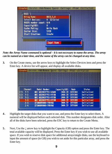
Note: the Array Name command is optional – it is not necessary to name the array. The array
can be named at a later time, and the name of the array can be changed at any time.
3. On the Create menu, use the arrow keys to highlight the Select Devices item and press the
Enter key. A device list will appear, and display all available disks.
4. Highlight the target disks that you want to use, and press the Enter key to select them. A
numeral will be displayed before each selected disk. This number designates disk order. After
all of the disks have been selected, press the ESC key to return to the Create Menu.
5. Next, Use the ↓ arrow key to highlight the Capacity (GB) option and press the Enter key. The
total available capacity will be displayed. Press the Enter key if you wish to use all available
space. If you wish to reserve disk space for additional arrays/single disks, use the keyboard to
input the amount of space (in GB) you wish to set aside for this particular array, and press the
Enter key.

10
Note: Multiple arrays can be created using the same set of disk drives. One physical drive can be
used to create up to 4 arrays. The Capacity option allows you to set aside disk space that be used
to create another array, set as a spare disk, or partitioned to act as a single disk (by the operating
system).
6. For redundant RAID arrays (RAID 1, 5, 10), select the Cache Policy:
Write Back – Provides higher write performance for redundant RAID arrays. Data is at risk
when there is a power failure, system kernel panic and unresponsive, abnormal conditions. Write Through – Writes directly to the disks (may reduce the risk of data loss during a
critical failure, but at the cost of lower performance).
Sector Size – Also known as “Variable Sector Size”. This option allows change the RAID
array’s logical sector size from 512b to 16K.
7. Use the arrow key to highlight the Start Creation item and press the Enter key.
The Window will show 2 options if create RAID: Background Initialize and Quick
Initialize.
11
Quick Init: The RAID array will be immediately accessible.
A. This option will delete all content on the disks.
B. This option will not perform disk array initialization. When new
HDD’s are used this option can be ignored since the there is no
data on the hard disks.
Background: The RAID array is accessible while disk initialization is being
performed.
A. This option will delete all content on the disks.
B. The initialization time will be longer when compared to
"Foreground" but the logical drives can be used during the
initialization process. Note: The BIOS interface cannot perform Background initialization. This action must be
performed using the WebGUI while running the operating system.
8. Press the Y (yes) key to create the array, or N (no) key to cancel the creation process. If you
press the Y, BIOS will show the following window.
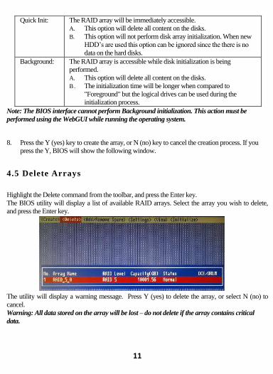
4.5 Delete Arrays
Highlight the Delete command from the toolbar, and press the Enter key.
The BIOS utility will display a list of available RAID arrays. Select the array you wish to delete,
and press the Enter key.
The utility will display a warning message. Press Y (yes) to delete the array, or select N (no) to
cancel.
Warning: All data stored on the array will be lost – do not delete if the array contains critical
data.

12
4.6 Add/Remove Spare Disks
The Add/Remove Spare command is used to assign a hard disk to act as a Spare Disk. Spare Disks
are used to automatically rebuild Redundant RAID arrays (RAID 1, 5, 6, 10, 50) in the case of disk
failure. As with creating RAID arrays, disks must be initialized before they can be used as spares.
To set a hard disk to act as a Spare Disk, use the arrow keys to select the target disk from the list of
initialized disks, and press the Enter key. To remove the Spare Disk setting from a hard disk,
highlight the spare disk, and press the Enter key.
Generally, single disks are designated to act as spares (disks that are not configured into RAID
arrays).
However, in some instances, disks that are members of RAID arrays may also be designated to act
as a spare. If the disks in question are part of a RAID array that did not utilize the full available
capacity at the time of creation, these disks may be used as spares. For example: a RAID 0 array
was created between two 200GB hard disks, but only 200GB of space (out of a grand total of
400GB), was assigned to that array. In this example, 200GB of disk space remains unallocated. This
unallocated space would allow these disks to be set as spares for a separate redundant array that falls
into the same capacity range (200GB).

13
4.7 Settings
To access the Settings menu, highlight the Settings command from the toolbar, and press the Enter
key. There are Select Boot Device and Parameter Setting options in the menu.
Select Boot Device – The RocketRAID 2720C2 can be used to boot the system. This option
allows you to select which disk/array will serve as the systems boot device. The BIOS interface
will display the selected boot device (disk or array) as the first device.
Note: RocketRAID series HBA do not support bootable devices over 2TB in size. Do not install
an operating system to any disk or array over 2TB.
In order to boot from a disk/array attached to the RocketRAID 2720C2, you may be required to
change the motherboard’s BIOS settings, and instruct it to boot from the controller.
Staggered Spinup – This menu includes various controller related settings and features.
The default value of this option is disabled. Enabling this setting will instruct the card to power up
the hard disks, sequentially (one disk approximately every 2 seconds). Not all disk support this
setting – consult the disk documentation for more information.
Warning: Western Digital hard disks do not support this setting. Enabling this setting is not
recommended. If enabled, these disks may not be detected by non-RAID controller

14
4.8 View
The View menu provides four options:
Devices – This option will display information for each disk hosted by the HBA.
RAID Array – This option will display information about each RAID array hosted by the
HBA. Highlight the target device and press the Enter to view details about the configuration.
Rescan Devices – This command will prompt the HBA to scan each port for devices. Use this
feature when attaching hard disks or arrays to the HBA.

15
5. Driver Installation (Windows)
Download the corresponding driver package from the official RocketRAID 2720C2 website.
Extract the contents to a directory of your choice.
1) After installing the RocketRAID host adapter, boot to the Windows operating system.
2) Windows should automatically detect the card, and displays the “Found New Hardware
Wizard”. Select “Locate and install driver software”. When Windows asks: “Windows needs
your permission to continue”, select “Continue”.
3) When asked to search online select “Don’t Search Online”.
4) Select “I don’t have disc, show me other options”.
5) And then select “Browse my computer for driver software”.
6) Browse to the location of the driver and click “Next”.
7) When asked: “Would you like to install this driver software?” select “Install”.
8) Reboot the system when prompted. The RocketRAID host adapter will be ready for use after
Windows reboots.
6. WebGUI Installation (Windows)
Download the corresponding WebGUI package from the official RocketRAID 2720C2 website.
Extract the contents to a directory of your choice.
1) Double-click “Setup.exe” to start installation. If you are running a 64-bit version of Windows,
you may need to right-click the icon, and select “Run as Administrator.”
2) Click “Run” to continue. The HighPoint Web RAID Management Service install screen will
display. Chick “Next” to continue.
3) Click “Yes” to install the Management Utility.
4) Specify the Destination folder and click “Next”. Confirm the install location, and click
“Next”.
5) Select the SAF-TE configuration file for the system’s chassis. If the system does not support
SAF-TE, select the default option “Skip and Configure Later”.
6) Specify the listening port. 7402 is the default setting, and recommended for most systems.
7) Choose to enable or disable Remote Access. Remote access allows the card to be managed
via a Web browser from a separate system.
8) Click “OK” to complete the installation procedure.

16
7. Driver Installation (Linux)
HighPoint provides an open source driver package for Linux platforms. Download the
corresponding driver package from the official RocketRAID 2720C2 product page, and extract the
contents to the directory of your choice.
Please refer to the included README file for instructions.
8. WebGUI Installation (Linux)
Download the corresponding WebGUI package from the official RocketRAID 2720C2 website.
Extract the contents to a directory of your choice.
Please refer to the included README file for instructions.
9. Starting the WebGUI
1) Double-click the “HighPoint Web RAID Management” Icon on the Desktop to start the Web
GUI. The system’s default Web Browser will open the login page.
2) Type in the default username and password to start the Web GUI.
3) User name: RAID
Password: hpt
4) Click Login. The Manage-Array screen will be displayed.
10. Using the WebGUI
Please refer to the online user guide for the basic function of using the WebGUI:
http://www.highpoint-tech.com/help/
The RocketRAID 2720C2 WebGUI provides additional cross-sync RAID functions.

17
Global page
Controller count indicates the number of installed RocketRAID 2720C2 host adapters.
Physical page
The Physical page shows controller & device information. Click Devices below each Controller
entry to view information about the RocketRAID 2720C2 and hosted storage devices.

18
Logical page
The logical page shows the logical and physical device information. The RAID management
function allows you to create RAID arrays with all available devices.
11. Customer Support and Contact Information
If you encounter any problems while utilizing the RocketRAID host adapter, or have any questions
about this or any other HighPoint Technologies, Inc. product, feel free to contact our Customer
Support.
Web Support: http://www.highpoint-tech.com/websupport/
E-mail address: [email protected]
HighPoint Technologies, Inc. websites:
http://www.highpoint-tech.com
19
FCC Part 15 Class B Radio Frequency Interference statement
This equipment has been tested and found to comply with the limits for a Class B digital device,
pursuant to part 15 of the FCC Rules. These limits are designed to provide reasonable
protection against harmful interference in a residential installation. This equipment generates
uses and can radiate radio frequency energy and, if not installed and used in accordance with
the instructions, may cause harmful interference to radio communications. However, there is no
guarantee that interference will not occur in a particular installation. If this equipment does
cause harmful interference to radio or television reception, which can be determined by turning
the equipment off and on, the user is encouraged to try to correct the interference by one or
more of the following measures:
Reorient or relocate the receiving antenna.
Increase the separation between the equipment and receiver.
Connect the equipment into an outlet on a circuit different from that to which the
receiver is connected.
Consult the dealer or an experienced radio/TV technician for help.
Modifications not expressly approved by the manufacturer could void the user’s authority to
operate the equipment under FCC rules.
This device complies with part 15 of the FCC Rules. Operation is subject to the following two
conditions: (1) this device may not cause harmful interference, and (2) this device must accept
any interference received, including interference that may cause undesired operation.
European Union Compliance Statement This Information Technologies Equipment has been tested and found to comply with the
following European directives:
European Standard EN55022 (1998) Class B
European Standard EN55024 (1998)


